Feedback
Table Of Contents
Console and Auxiliary Port Cables and Pinouts
Console Port Cables and Pinouts
Auxiliary Port Signals and Pinouts
T1/PRI and E1/PRI Card Port Pinouts
T1/PRI and E1/PRI Card Cable Assemblies and Pinouts
Cabling Specifications
This appendix provides the following cabling and pinout information for the Cisco AS5300 universal access server:
•
Console and Auxiliary Port Cables and Pinouts
•
•
Note
Console and Auxiliary Port Cables and Pinouts
The access server arrives with a console and auxiliary cable kit, which contains the cable and adapters you need to connect a console (an ASCII terminal or PC running terminal emulation software) or modem to your access server. The console and auxiliary cable kit includes:
•
•
•
•
For console connections, proceed to the section "Console Port Cables and Pinouts" later in this appendix; for modem connections, proceed to the section "Auxiliary Port Signals and Pinouts" later in this appendix.
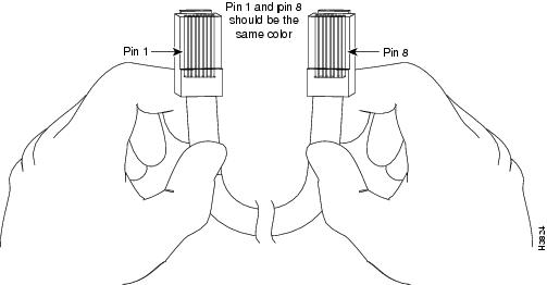
Identifying a Rollover Cable
You can identify a rollover cable by comparing the two modular ends of the cable. Holding the cables side-by-side, with the tab at the back, the wire connected to the pin on the outside of the left plug should be the same color as the wire connected to the pin on the outside of the right plug. (See .) If your cable was purchased from Cisco Systems, pin 1 will be white on one connector, and pin 8 will be white on the other connector (a rollover cable reverses pins 1 and 8, 2 and 7, 3 and 6, and 4 and 5).
Figure D-1 Identifying a Rollover Cable
Console Port Cables and Pinouts
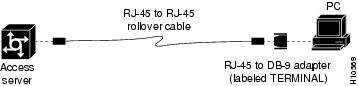
Use the RJ-45-to-RJ-45 rollover cable and RJ-45-to-DB-9 female DTE adapter (labeled TERMINAL) to connect the console port to a PC running terminal emulation software. shows how to connect the console port to a PC. lists the pinouts for the asynchronous serial console port, the RJ-45-to-RJ-45 rollover cable, and the RJ-45-to-DB-9 female DTE adapter (labeled TERMINAL).
Figure D-2 Connecting the Console Port to a PC
Table D-1 Console Port Signaling and Cabling Using a DB-9 Adapter
RTS
11
8
8
CTS
DTR
2
7
6
DSR
TxD
3
6
2
RxD
GND
4
5
5
GND
GND
5
4
5
GND
RxD
6
3
3
TxD
DSR
7
2
4
DTR
CTS
81
1
7
RTS
1 Pin 1 is connected internally to pin 8.
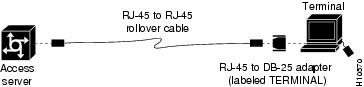
Use the RJ-45-to-RJ-45 rollover cable and RJ-45-to-DB-25 female DTE adapter (labeled TERMINAL) to connect the console port to a terminal. shows how to connect the console port to a terminal. lists the pinouts for the asynchronous serial console port, the RJ-45-to-RJ-45 rollover cable, and the RJ-45-to-DB-25 female DTE adapter (labeled TERMINAL).
Figure D-3 Connecting the Console Port to a Terminal
Table D-2 Console Port Signaling and Cabling Using a DB-25 Adapter
RTS
12
8
5
CTS
DTR
2
7
6
DSR
TxD
3
6
3
RxD
GND
4
5
7
GND
GND
5
4
7
GND
RxD
6
3
2
TxD
DSR
7
2
20
DTR
CTS
81
1
4
RTS
1 You can use the same cabling to connect a console to the auxiliary port.
2 Pin 1 is connected internally to pin 8.
Auxiliary Port Signals and Pinouts
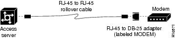
Use the RJ-45-to-RJ-45 rollover cable and RJ-45-to-DB-25 male DCE adapter (labeled MODEM) to connect the auxiliary port to a modem. shows how to connect the auxiliary port to a modem. lists the pinouts for the asynchronous serial auxiliary port, the RJ-45-to-RJ-45 rollover cable, and the RJ-45-to-DB-25 male DCE adapter (labeled MODEM).
Figure D-4 Connecting the Auxiliary Port to a Modem
Ethernet Port Pinouts
and list the pinouts for the Ethernet 10BaseT and 100BaseT ports, respectively.
T1/PRI and E1/PRI Card Port Pinouts
lists the Quad T1/PRI card port pinouts.
Table D-6 Quad T1/PRI Card Port Pinouts
1
RX Tip
2
RX Ring
3
RX Shield
4
TX Tip
5
TX Ring
6
TX Shield
7
-
8
-
T1/PRI and E1/PRI Card Cable Assemblies and Pinouts
Eight serial cables are available from Cisco Systems for connecting the E1/PRI and T1/PRI card ports.
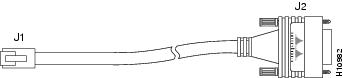
Figure D-5 RJ-45-to-DB-15 Interface Cable
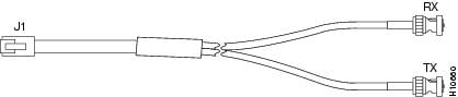
Figure D-6 RJ-45-to-BNC Interface Cable for 75-Ohm, Unbalanced Connections
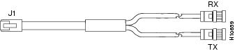
Figure D-7 RJ-45-to-Twinax Interface Cable for 120-Ohm, Balanced Connections
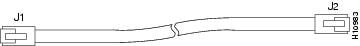
Figure D-8 RJ-45-to-RJ-45 Interface Cable
Note
Figure D-9 RJ-45-to-Bare Wire Interface Cable
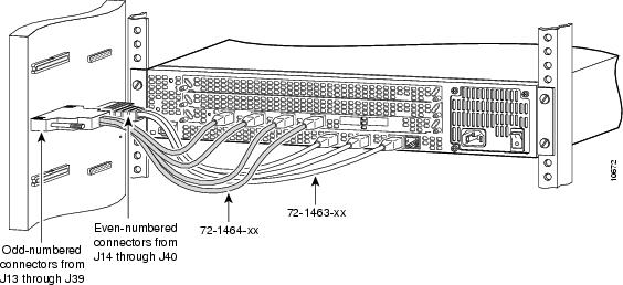
Figure D-10 /E1 (8) PRI Cable (72-1492-xx) Used in an Access Server Shelf
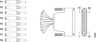
Figure D-11 T1/E1 (8) PRI Cable (72-1492-xx)