Feedback
Table Of Contents
Replacing Memory Chips
This appendix contains procedures on how to replace memory chips in the access server field-replaceable units. The appendix contains the following sections:
Removing the Chassis Cover
This section describes how to open the chassis by removing the chassis cover.
Required Tool
You need the following tool:
•
Medium Phillips screwdriver
Safety Recommendations
Note the following safety recommendations:
Warning
Before opening the chassis, disconnect the telephone-network cables to avoid contact with telephone-network voltages.
Warning
Do not work on the system or connect or disconnect cables during periods of lightning activity.
Warning
Do not touch the power supply when the power cord is connected. For systems with a power switch, line voltages are present within the power supply even when the power switch is off and the power cord is connected. For systems without a power switch, line voltages are present within the power supply when the power cord is connected.
Warning
Before working on a chassis or working near power supplies, unplug the power cord on AC units; disconnect the power at the circuit breaker on DC units.
NVRAM in the universal access server uses an internal lithium battery to maintain data. Although this is not a field-serviceable component, we are required to provide the following safety warning:
Warning
There is the danger of explosion if the battery is replaced incorrectly. Replace the battery only with the same or equivalent type recommended by the manufacturer. Dispose of used batteries according to the manufacturer's instructions.
Warning
Before working on equipment that is connected to power lines, remove jewelry (including rings, necklaces, and watches). Metal objects will heat up when connected to power and ground and can cause serious burns or weld the metal object to the terminals.
Chassis Cover Removal
You must open the access server chassis to gain access to its interior components: boot read-only memory (ROM) software, dynamic random-access memory (DRAM) SIMMs, and Flash memory SIMMs. (When you replace the boot ROMs, you must also remove all feature cards in the chassis.)
Take these steps:
Step 1
Step 2
Warning
Before performing any of the following procedures, ensure that power is removed from the DC circuit. To ensure that all power is OFF, locate the circuit breaker on the panel board that services the DC circuit, switch the circuit breaker to the OFF position, and tape the switch handle of the circuit breaker in the OFF position.
Figure B-1 DC Power Supply Connections
(a)
(b)
(c)
(d)
Step 3
Step 4
Step 5
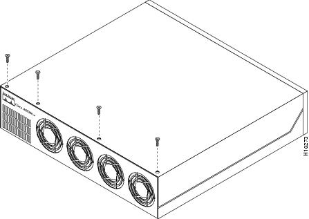
Figure B-2 Removing the Chassis Cover Screws
Step 6
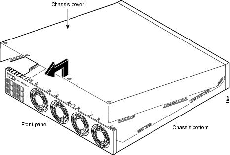
Figure B-3 Removing the Chassis Cover
Replacing Boot ROMs
To upgrade the boot ROM software to a new software image, you must replace the existing boot ROMs.
Required Tools and Equipment
You will need the following tools and equipment:
•
•
•
•
Boot ROM Replacement
Take these steps:
Step 1
For DC-powered units only, note the following warning.
Warning
Before performing any of the following procedures, ensure that power is removed from the DC circuit. To ensure that all power is OFF, locate the circuit breaker on the panel board that services the DC circuit, switch the circuit breaker to the OFF position, and tape the switch handle of the circuit breaker in the OFF position.
Step 2
Step 3
Step 4
Step 5
Step 6
Step 7
CautionThe notch in the ROM must align with the notch in the socket on the system card. If the ROM is installed backwards, it will be damaged when the access server is powered ON.
Step 8
Step 9
Step 10
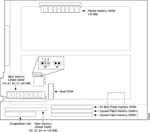
Figure B-4 System Card Layout
Replacing DRAM SIMMs
This section describes how to replace DRAM SIMMs on the system card. You might need to upgrade the DRAM SIMMs for the following reasons:
•
•
The system card contains three sockets for DRAM SIMMs (see ):
•
•
Required Tools and Equipment
You need the following tools and equipment:
•
•
DRAM SIMM Replacement
Take these steps:
Step 1
For DC-powered units only, note the following warning.
Warning
Before performing any of the following procedures, ensure that power is removed from the DC circuit. To ensure that all power is OFF, locate the circuit breaker on the panel board that services the DC circuit, switch the circuit breaker to the OFF position, and tape the switch handle of the circuit breaker in the OFF position.
Step 2
Step 3
Step 4
Step 5
Step 6
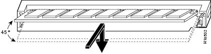
CautionTo prevent damage, do not press on the center of the SIMM. Handle the SIMM carefully.
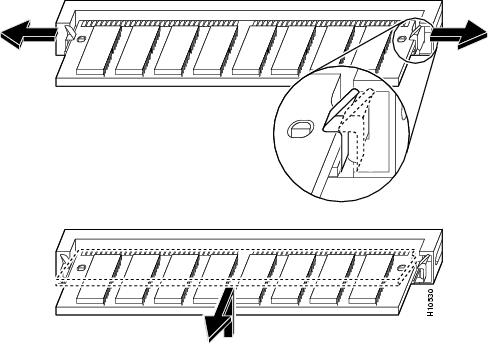
Figure B-5 Removing and Replacing the DRAM SIMM
Step 7
Step 8
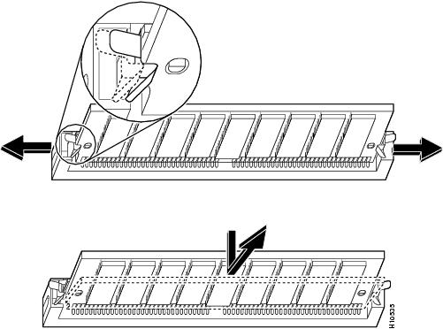
Figure B-6 Inserting the New DRAM SIMM into the Socket
Step 9
Step 10
Step 11
Step 12
Replacing Flash Memory SIMMs
The system card contains three sockets for Flash memory SIMMs (see ):
•
•
The Flash memory SIMMs must be purchased from Cisco. For ordering information, refer to the Information Packet that accompanied your access server.
Required Tools and Equipment
You need the following tools and equipment:
•
•
Flash Memory SIMM Replacement
Take these steps:
Step 1
For DC-powered units only, note the following warning.
Warning
Before performing any of the following procedures, ensure that power is removed from the DC circuit. To ensure that all power is OFF, locate the circuit breaker on the panel board that services the DC circuit, switch the circuit breaker to the OFF position, and tape the switch handle of the circuit breaker in the OFF position.
Step 2
Step 3
Step 4
Step 5
CautionTo prevent damage, do not press on the center of the SIMMs. Handle each SIMM carefully.
Step 6
Figure B-7 Removing the Flash Memory SIMM
CautionSome Flash memory SIMMs have the components mounted on the rear side. To prevent damage when you insert the SIMM, always use the polarization notch as a reference, not the position of the components on the SIMM.
Step 7
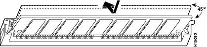
Figure B-8 Inserting the Flash Memory SIMM
Step 8
Step 9
Step 10
Step 11
Replacing the Chassis Cover
This section describes the procedure for replacing the chassis cover.
Required Tool
You need the following tool:
•
Chassis Cover Replacement
To replace the chassis cover, take these steps:
Step 1
Step 2
Step 3
•
•
•
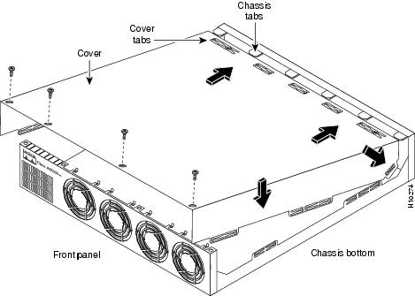
When the chassis cover is properly assembled, no tabs are visible, as shown in .
Step 4
Step 5
Step 6
Figure B-9 Replacing the Chassis Cover
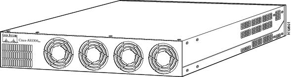
Figure B-10 Cisco AS5300 Chassis
Step 7
Warning
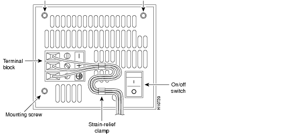
The illustration shows the DC power supply terminal block. Wire the DC power supply using the appropriate wire terminations at the wiring end, as illustrated. The proper wiring sequence is ground to ground, positive to positive, and negative to negative. Note that the ground wire should always be connected first and disconnected last.
Figure B-11 DC Power Supply Connections
CautionDo not overtorque the terminal block contact screws. The recommended torque is 8.2 ± 0.4 inch-lb.
(a)
(b)
(c)
(d)
Warning
After wiring the DC power supply, remove the tape from the circuit breaker switch handle and reinstate power by moving the handle of the circuit breaker to the ON position.
Step 8
The internal power supply fan should power on.