Cisco Converged 5G xHaul Transport

This white paper outlines the Cisco strategy for the transport network that will underpin the worldwide adoption of 5G technologies and delivery of applications. Along with major technological change to the mobile core and radio access network (RAN), operators will also need to evolve their transport networks to cost-effectively deliver a satisfying mobile broadband experience, while simultaneously meeting the scale requirements for massive Internet of Things (IoT), and the ultra-low latency requirements for real-time applications.

Executive summary

Worldwide, the promise of 5G services looks to be simultaneously an evolutionary and revolutionary opportunity. Massively scalable, low-latency enabled applications will open up new ecosystems, business models, and creativity across the enterprise and residential markets in every industry.

For mobile operators, the opportunity comes from creative new business models, innovative new revenue streams, and lean operational efficiency, all directly contributing to a more profitable set of offerings and robust business. However, the evolution of the mobile operator’s network is a significant financial and engineering undertaking that must be thought through from end to end. The new network infrastructure must simultaneously satisfy exploding bandwidth demands, massive logical scale, and the incredibly low-latency needs of new applications and services in an efficient, automated, programmable manner.

In enabling these new use cases, 5G evolves existing technologies and introduces new capabilities, such as new radio (NR), a strong reliance on virtualized functions, the introduction of network slicing and Control and User Plane Separation (CUPS). These developments, in turn, will have significant impacts on the underlying network. For example, to boost capacity, the footprint of the network will need to expand significantly. To host new ultra-reliable low latency communication (uRLLC) and massive machine-type communication (mMTC) applications efficiently it will need to be able to integrate regional data centers and distributed compute seamlessly - closer to the endpoints in the network.

Another key attribute of the 5G transport infrastructure will be to easily carve out and reuse capacity, compute, and resiliency, and guarantee latency by supporting network slicing. Operators will have to manage the network using a completely new approach in order to enable the rapid provisioning and service automation required. In addition to the pure mobility requirements, operators must also consider how their network caters to the different classes of services they deliver, such as fixed line and broadband customers; as well as supporting the different customer types (consumer, small to medium business, and enterprise).

Cisco believes the most flexible and efficient transport architecture to achieve this will be based on packet technology with segment routing. Segment Routing can cost-effectively deliver this flexibility, affordability, and visibility in the transport network. It is capable of supporting consumer, enterprise, fixed, and mobile services across the transport network – all regardless of access technology.

This white paper outlines how such a converged xHaul transport network can be realized, starting with new requirements it must meet; the new technologies it needs to deploy 5G-capable services; and finally, the design features necessary to cost-effectively build and operate it.

Current transport architectures for mobile operators

Just as mobile services and technologies have evolved from circuit switched voice services to packet-technology-based data and voice services, the transport network has evolved rapidly from a purely time division multiplexing (TDM) infrastructure to a packet-based infrastructure.

Cisco has been at the forefront of this transition with our Unified Multiprotocol Label Switching (MPLS) solution, designed around standards-based packet technologies and carried over a high-capacity optical infrastructure. Globally, mobile operators have comprehensively adopted Unified MPLS, setting the standard for IP-based mobile service delivery.

There are three fundamental aims of Unified MPLS. The first is obvious; to build an infrastructure able to support the packet and TDM services needed for a 2G/3G/4G mobile network. The second is scalability, such that the architecture can support the networking requirements of the very largest operators using packet technology starting from the core all the way to the access layer of the network. The third is building a cost-effective infrastructure, so that as you move from the core toward the access, the forwarding and control plane of the network equipment can become simpler and more cost-effective.

Unified MPLS relies on splitting the network into different domains and introducing a hierarchy that has an IP core domain (not to be confused with the mobile core) in the center, with aggregation and access domains surrounding it. Each domain is isolated from the others and runs its own Interior Gateway Protocol (IGP). Where inter-domain connectivity is required to deliver a service, Border Gateway Protocol (BGP) carries the appropriate inter-domain prefixes, allowing communication from end to end.

This technique has proven to be extremely successful and many 3G and 4G networks are deployed today using Unified MPLS running in the core, metro, and access networks. Currently, some mobile networks that use this architecture support in excess of 150,000 network devices.

Why do we need a new approach?

Although extremely successful and widely deployed, there are complexities to the Unified MPLS architecture when deployed in extremely large networks. These revolve around the complexity of the control plane, the number of control plane protocols, and the amount of device-level configurations required when building a service that spans many domains.

The introduction of 5G introduces additional challenges, which include:

  • Footprint expansion due to the densification of the radio
  • Need to incorporate the network or edge data center seamlessly into the transport network
  • Use of virtualized network functions (VNF) for radio and mobile core functions
  • Network slicing
  • Control plane and user plane separation introduced by the CUPS architecture

These changes, plus a desire by many operators to build a single converged transport architecture for their entire customer base, reinforces the need for an end-to-end packet infrastructure that can support a wide range of layer 2 and layer 3 services.

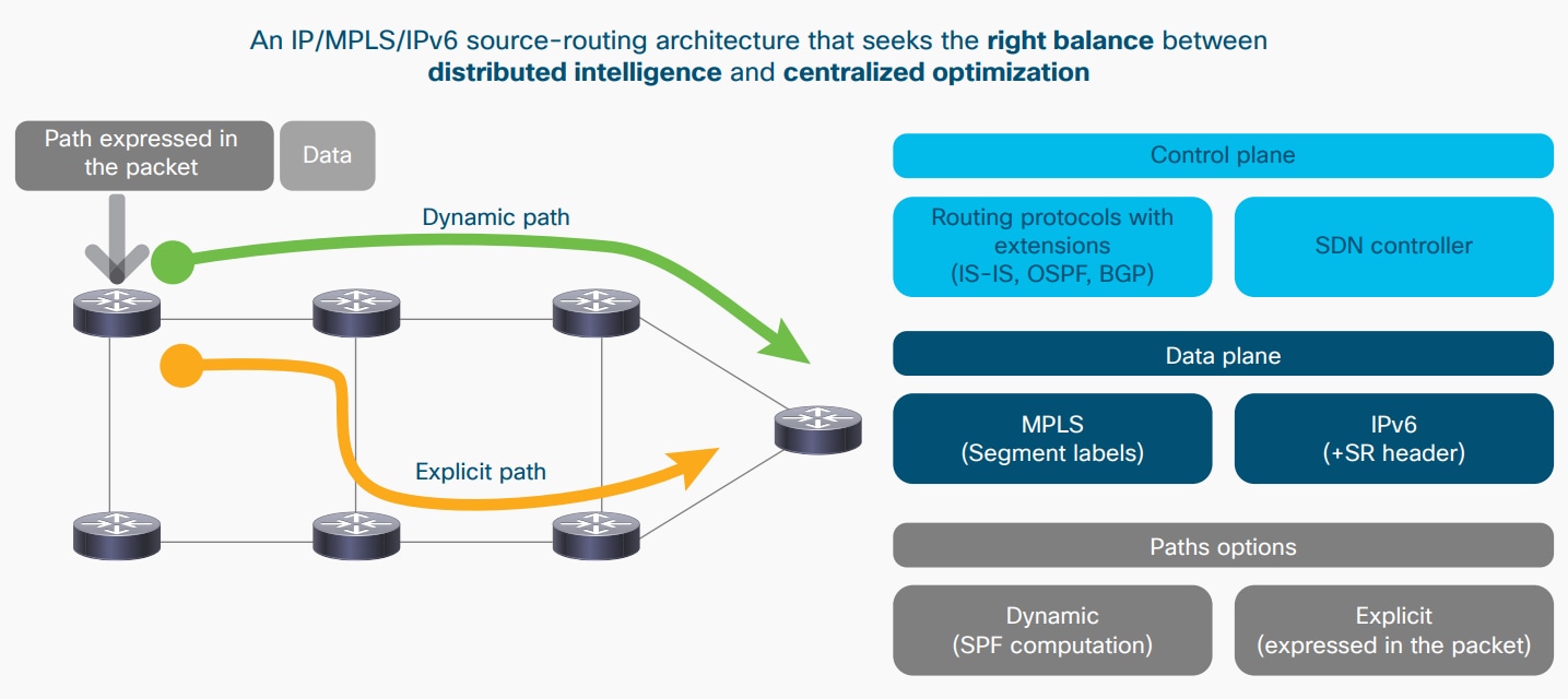
The proposed solution is to evolve the transport network’s control and data plane toward segment routing, with the option of moving toward an infrastructure orientated around software-defined networks (SDN). This approach reduces control plane protocols, such as Label Distribution Protocol (LDP) and Resource Reservation Protocol – Traffic Engineering (RSVP-TE), removes flow state from the network, and provides several options for control plane implementation. These options range from a fully distributed implementation to a hybrid approach where the router and the SDN controller divide the functionality between themselves.

This transport infrastructure is capable of overlaying a wide range of service technologies, with associated IP-based service-level agreements (SLAs), including BGP-based VPN technologies, such as EVPNs and VPNv4/v6s, and emerging SD-WAN VPN technologies.

5G network requirements

The 3GPP standards organization and 5G industry developers are specifying the main features of 5G. Figure 1 outlines the functionality already specified and to be available in upcoming 3GPP releases.

Figure 1. 5G technology evolutions

In looking at this list, one can notice that there is no significant mention of what underlying network is required to deploy these new technologies. This is understandable, as people writing the 5G standards rightly focus upon the mobile functionality. On the other hand, operator architects should understand that every one of these new 5G capabilities places new demands on the underlying transport network and so treatment of the issue is important.

In the following sections, we outline the key sets of requirements that an xHaul transport network must address to support 5G successfully.

IP orientated with service-level agreements (SLA)

The importance of Internet Protocol (IP) and the efficient transportation of packets has increased with each subsequent 3GPP generation of mobile technology. 4G was the first mobile technology that relied entirely on IP and packet technology. 5G continues this trend and relies even more on the ability to route packets efficiently to their destination combined with an associated IP-based SLA.

Several key 5G developments are driving further adoption of an IP-routed infrastructure:

  • 5G supports a number of key use cases, including enhanced mobile broadband (eMBB), ultra-reliable low latency communications (URLLC), and massive machine type communications (mMTC). Packets associated with these different use cases have bandwidth requirements that range from very low to very high, and packet delivery requirements from best effort to guaranteed service quality. Given that the traffic will originate and terminate on IP devices, the overall transport infrastructure must be able support these requirements at an IP level.
  • 5G envisions a transport architecture that separates the mobile control plane and the user plane (CUPS). Normally, the mobile control plane will reside in a central location, while the user plane functions will reside in a location best suited to the use case or service it is supporting. This location of the user plane may be close to where the control plane resides, it could be distributed around the network, or even use a mixture of both approaches. To build a flexible CUPS architecture requires the mobile control plane to be able to communicate, using an IP-orientated protocol, with the user plane functions regardless of where they reside in the network. It also requires that the user equipment (UE) can use IP protocols to reach the appropriate user plane function (UPF) for the service it is servicing. The most scalable, controllable, and flexible approach is to utilize a common layer 3 routed service network for these communications, as point-to-point services are clearly unsuitable and layer 2 Ethernet Tree (E-Tree) and Ethernet LAN (E-LAN) services will face scalability and control issues as the number of user plane components increase.
  • A key concept in 5G is network slicing, which is the ability to build what looks like discrete end-to-end networks for different 5G use cases or customers. However, one requirement of network slicing is that sometimes components may need to be shared between slices. For example, the multiple slices may share the same mobile control plane but each individual slice may have its own user plane function. For this to work, the requested mobile control plane function needs to be accessible to both slices. In this scenario, using an IP layer, with appropriate firewalling, to connect the slices together provides the optimal solution.

These new 5G capabilities further strengthen the case for IP infrastructure over any previous generation of mobile. In addition to the transport of packets, the transport infrastructure must support packet-based quality of service (QoS) and it must be programmable in order to support different IP-forwarding paradigms: ranging from simple shortest path routing to pre-defined traffic-engineered tunnels.

Network scale and capacity

5G is going to increase the footprint of the transport networks, increase the number of devices, and significantly increase the overall capacity of the network. There are a couple of reasons for this:

5G technology is promising to increase radio bandwidth significantly by moving to higher frequencies, increasing the density of radio sites and improved modulation and antenna techniques. This has two effects: 1) To accommodate the additional radios, the footprint of the transport network will increase. 2) The core capacity of the network will increase because of the improved radio bandwidth, as well as the massive increase of endpoints due to specific 5G use cases (see the second reason below).

5G use cases supporting the development of IoT, namely massive machine type communications (mMTC), means that transport and mobile core networks will need to cater to an enormous increase in the number of endpoints, and thus, the logical scale that the network will need to accommodate.

Emerging RAN architectures

In order to support the changing nature of the 5G network, it is clear that one of the most important factors to address is the current and future architecture of the RAN, the link that the radio sites use to connect to the transport network. Not only is this where operators spend most of their money today, but being geographically dispersed, it is also difficult to manage. Therefore, any development or evolution of the RAN to improve the efficiency or reduce the operational costs requires serious consideration.

Traditionally, we implemented the RAN as a distributed RAN (D-RAN) architecture, where all the radio functionality (the NodeB or eNodeB) resided in the cell site, which then exchanged IP packets with the mobile core via the backhaul network. The IP protocol was used to carry the traffic streams, and the data rates needed were roughly equivalent to the combined user data rates of user equipment that was utilizing the radios hosted in that cell site. With 4G, and more so with 5G, an alternative to the D-RAN is the disaggregated or centralized RAN (C-RAN), whereby the upper layers of the radio functions are separated from the lower layers and moved to a shared, centralized location.

Figure 2 shows the different 5G architectures emerging with RAN.

Figure 2. 5G RAN architectures

For 5G, the industry has consolidated around three principal approaches to splitting the radio functions between the various components of the RAN.

The first two approaches are low-level splits (LLS), where the physical functions of the radio are split between the radio unit (RU) or radio equipment (RE) at the cell site and a remotely located distributed unit (DU) or radio equipment controller (REC). This distributed unit function can be located anywhere from the cell site itself out to some distance away (typically up to 10-20 Km).

The industry refers to the first of these low-level splits as an option 8 split, which uses a common public radio interface (CPRI) TDM interface between the radio unit and distributed unit sites. Since CPRI is based on regular time-domain samples and the channel is “always on,” it is carried as a constant bit stream, and consumes bandwidth proportional to the number of the antennas and bandwidth of the radio channels. CPRI option 8 splits have been deployed in 4G C-RAN environments but most operators believe it is unsuitable in 5G deployments due to the huge increase in bandwidth it will need in the CPRI transport. This is because the increased number of antennas (due to the adoption of multiple-input multiple-output [MIMO] antennas), higher frequencies in millimeter wave radios, and greatly increased width of radio channels.

The second low-level split is known as an option 7 split and is based on frequency domain samples, with the advantage of significantly lower bandwidth requirements, which are not constant as in option 8, but a function of the amount of user traffic. Efforts by the various RAN consortia to standardize this split are underway, but what is commonly accepted is that this interface will use Ethernet (packet) for transport. The industry now broadly agrees that if a 5G deployment uses a low-level split architecture, it will be based on option 7.

Although there are technical differences between an option 7 and an option 8 split and differences in the implementations of these splits between various consortia, what is common between them is that both these levels of split specify mechanisms to carry digitized radio between the radio unit and the distributed unit. The challenge for this type of RAN is that it requires a transport with high bandwidth (much greater than the sum of data rates from the users) and very low latency. The industry refers to this network as the fronthaul network as opposed to the backhaul network, which describes the D-RAN case where all radio equipment is installed at the cell site (See Figure 2).

The third approach is a high-level split (HLS), known as an option 2 split, where an IP interface exists between the previously seen distributed unit and the centralized unit. In this scenario, the network between these components is commonly referred to as the midhaul network, since it lies between the fronthaul and backhaul networks. The bandwidth requirements of the midhaul are much lower than the fronthaul network–roughly equivalent to the backhaul network–although it does require lower round-trip time (RTT) delays.

It is clear that decisions made about which RAN architecture is chosen and level of virtualization employed by the network and radio controllers will significantly impact the way the transport infrastructure is constructed and also change the bandwidth and latency requirements of different portions of this network.

Network data centers and multi-access edge compute

The motivation for network data centers is to provide a cloud computing facility within the transport network, with the idea of hosting virtual network functions (VNFs) and virtualized applications in these facilities. The multi-access edge compute (MEC) approach takes the concept of the network data center one step further by distributing the network data centers out close to the network edge. The aim is to place functions closer to the end user, which should improve the end user’s service experience as well as reduce the load on the transport infrastructure and minimize the impact radius of any possible failures.

5G is one of the first standards-based technologies to envisage extensive use of network functions virtualization (NFV) by using this approach. Centralized network data centers will typically host the mobile core components associated with the control plane, while smaller, dispersed MEC data centers will host both virtualized RAN components (such as the centralized unit) and mobile core components associated with the user plane (such as user plane function [UPF]). Additionally, it would be advantageous to place user service functions, such as applications associated with uRLLC services and content delivery network (CDN) functions (potentially shared between fixed and mobile users) at the MEC sites. The industry expects that eventually MEC-like facilities could appear at all levels of the network, but this is likely to be a gradual process and will depend upon the use cases and RAN architectures employed by operators.

Using this approach creates a strong dependency between the traditional WAN infrastructure and the network data centers and it is important that the control and data planes are closely integrated to allow end-to-end services to be built in a seamless fashion.

Low-latency 5G services

An additional consideration for both the RAN and mobile core is low-latency 5G applications that require round-trip times (RTT) in the order of a few milliseconds. In order to provide this kind of service, an operator’s network must consider:

  • Control and user plane separation (CUPS) architecture that allows user data sessions to be terminated outside of the traditional mobile core locations, and that applications associated with these services are accessible without routing all the traffic via the mobile core
  • User plane function (UPF) and the low-latency application compute resources sited closer to the end user to reduce the latency introduced by the transport of data over long distances

Since the speed of light determines how quickly traffic can traverse a network, desire for low-latency applications and virtualized network functions determines where to site the network data centers, which may have significant commercial consequences, as operators may have limited options for appropriate locations to deploy equipment.

5G fixed mobile convergence

Although the current release of the 3GPP standards does not yet cover the use case of fixed mobile convergence (FMC), both 3GPP and the Broadband Forum are working on addressing the issue. As noted earlier in this paper, for a proper return on investment (ROI) for mobile service providers, the 5G buildout must include a plan that converges their fixed services with their xHaul network. The consequences of this work is that the transport network needs to be able to support existing VPN capabilities, regardless of access technology, e.g. enterprise VPNs and Internet access. These VPN technologies will be also the key feature to deliver different network slices in the shared transport network.

5G network slicing

5G specifies network slicing as a means to allocate a piece of an operator’s mobile network for different use cases, subscriber services, and classes of customers. Network slicing is an end-to-end partitioning of the network resources and network functions, so that selected services and customers may run in isolation from each other for a specific business purpose. The slice refers to every aspect of the 5G architecture, including radio, transport network, mobile core infrastructure, as well the orchestration infrastructure needed to manage and operate a slice. When referring specifically to the network infrastructure, it is necessary to meet the following requirements:

1. Transport slice management – This refers to the ability to create, modify, and delete a complete 3GPP network slice, including any actions required to the transport layer itself. It includes per-slice operations, administration, and maintenance (OAM) capabilities to allow both the slice application owner and the operator to monitor the health and performance of the slice.

2. Resource reservation – This refers to the ability to reserve transport resources for a transport slice.

3. Slice isolation – Any single transport slice should be isolated from other transport slices at the proper performance, operational, security, and reliability levels that are dictated by the service policy of the application or end user.

4. Abstraction – This refers to the ability to utilize resources to model and build a transport infrastructure suitable for the needs of a slice.

One of the more contentious issues associated with transport layer slicing is whether the slice is ‘hard’ or ‘soft’. In both cases, they need to meet the requirements outlined above, but the difference between them revolves around the level of resource sharing between different slices. In the case of a hard slice, the slice has dedicated resources (particularly bandwidth) dedicated to it and is not shared with other slices. Alternatively, the soft slice resources can be shared between slices, while maintaining proper SLA requirements, as well as return the resources to the network when the resources are no longer needed.

xHaul transport network for 5G

Cisco believes that a converged, end-to-end packet infrastructure, beginning in the access layer and stretching via the network data center all the way to the core, based upon segment routing and packet-based QoS, provides the underlying xHaul transport network (see Figure 3). This provides the most flexibility of application placement, the best scalability, the most robust reliability, and the leanest operational costs. On top of this, we layer VPN services, either based on BGP-based VPNs or business software-defined WAN (SD-WAN) technologies, to provide the means to support a multi-service environment capable of supporting strict SLAs.

Figure 3. Overall end-to-end architecture

This architecture provides transport capabilities needed to support the following capabilities:

  • Converged, meaning it should be able to concurrently support:
    • Fixed and mobile traffic
    • Enterprise, small and medium businesses (SMB), IoT, and consumer services
    • Retail and wholesale business models
    • Voice, video, and data
  • End-to-end packet-based infrastructure based on an underlay of segment routing
  • Enables the encapsulation and transport of legacy RAN protocols (e.g. CPRI), and supports all possible fronthaul RAN, midhaul RAN, and backhaul architectures
  • Flexibility, supporting a range of services, including high bandwidth, best effort, and low latency applications
  • High-bandwidth WAN network; optical infrastructure overlaid with high-performance hardware routers and switches that can deliver massive increases in throughput while retaining feature-efficient power and space footprints
  • Virtualized service functions and user applications, deployed using commercial off-the-shelf (COTS) equipment in distributed, network-orientated data centers
  • Delivers to strict SLA requirements, controlling an end-to-end data-forwarding plane that encompasses the WAN to the data center
  • VPN-capable, implementing network-based BGP layer 1 / layer 2 / layer 3 VPNs combined with support for emerging customer premises equipment (CPE) based SD-WAN solutions. In both cases, they should be able to utilize capabilities of the underlying network to meet SLA expectations based on QoS classes and traffic engineering.
  • Accurately timed and synchronized in frequency, phase, and time, for all network topologies and transport types
  • Able to support open, multi-vendor RAN architectures such as O-RAN
  • Orchestrated and automated with model-driven provisioning and monitored with advanced analytics and model-based telemetry
  • Security embedded in the network, and built upon a chain of trust

Segment Routing data plane

Segment Routing is a technology invented by Cisco. Subsequently, a number of key operators drove the definition and adoption further, which has then attracted considerable interest from the wider operator and vendor community. For the last several years, the Internet Engineering Task Force (IETF) has continued to push the technology down a standardization track.

Segment Routing is based on a source routing paradigm, where the source node defines the path that a packet is going to take through the network. The source node inserts an ordered list of segments into the packet, which in the case of MPLS, is a set of labels; or in the case of IPv6, a set of segment IDs (SIDs) carried in a segment routing header (SRH). Because the segments are calculated and inserted on the source node, intermediate nodes simply read the appropriate segment labels/IDs within the packet header to execute the associated instructions. Very importantly, this means that the intermediate nodes do not need to hold any flow state, which greatly simplifies the network control plane. Figure 4 outlines the Segment Routing architecture.

Figure 4. Segment Routing architecture

There are multiple types of segments defined in Segment Routing and it is quite a broad topic. For a more detailed explanation of the technology, refer to: http://www.segment-routing.net/

Segment Routing control plane

The Segment Routing control plane can run purely as a distributed control plane, or where more complex forwarding paradigms (such as inter-domain routing) are required, it can use a hybrid approach. The hybrid approach splits the responsibilities: the routers distributed through the network host some functions while external SDN controllers calculate others, for example the definition of Segment Routing policies and inter-domain paths. In both approaches, the distributed routers run those functions needed to rapidly distribute the link state database, as well as calculate the shortest path routing tables, monitor the links to the attached nodes, and rapidly recover in the event of a failure.

SDN controller

Software-defined networks (SDN) and SDN controller are loaded terms and their definition depends on who you ask. In some cases, these networks are all-encompassing and involve all the topics of orchestration, automation, service assurance, and management of flows within the network. In others definitions, it refers purely to management of flows in the network. For the following discussion, we examine only the flow management component of SDN and cover other vital functions such as orchestration, automation, and service assurance elsewhere.

As noted above, Segment Routing does not require an external controller function, but as the segment-routing-policy use cases become more complex, or the network increases in scale and extends beyond a single domain, then the use of an SDN controller becomes more important.

Cisco’s SDN controller, called Cisco Segment Routing – Path Computation Element (SR-PCE), is based on the Cisco IOS® XR network operating system and can be hosted on either a physical or virtual device. SR-PCE has a northbound interface to the application layer via APIs. Southbound into the transport network, it collects the topology using standards-based protocols such as BGP-LS and subsequently is able to compute and deploy Segment Routing policies across the network. The Segment Routing policy algorithms used by SR-PCE have been purpose-built and specifically designed around segment routing.

Delivering SLAs with segment routing

Segment Routing policies and Segment Routing paths (the terms are interchangeable) are the methods used to implement an SLA in the network infrastructure. The Segment Routing control and data plane concurrently supports different SLA types while running on the same underlying networking infrastructure. Examples include:

1. Shortest path routing combined with equal-cost multipath (ECMP). This is the default policy supported by Segment Routing and is calculated on the network equipment by the IGP. It matches exactly the way an IP network forwards traffic, and is implemented by using a Segment Routing prefix segment.

2. Flexible Algorithm (commonly referred to as Flex-Algo). Traditional routing protocols, such as Open Shortest Path First (OSPF) and Intermediate System-to-Intermediate System (IS-IS), use the IGP metric on links and the “Shortest Path First” algorithm to calculate the “best” path between an ingress and egress point in the network. For many services this approach is sufficient, however this approach cannot, for example, take into account real-time link latency, utilization, and loss, whether an ECMP shares links that use the same underlying fiber. Flex-Algo is a new capability in segment routing that enables an operator to define their own custom flexible algorithm, based on a wide range of variables, including link latency, loss, bandwidth, and shared risk link groups (SRLG), to achieve a specific aim. For example, an operator may have an IP network using highly reliable fiber paths which they own and less reliable fiber paths which they lease and they want to support a highly reliable, low latency IP service. Flex-Algo can achieve this by building a routing table that optimizes based on real-time link latency, only on links owned by the operator. Other commonly discussed Flex-Algo use cases include bandwidth-guaranteed paths and routing between ingress and egress points using disjoint paths.

3. Segment Routing Traffic Engineering (SR-TE) paths. In this case, the path is explicitly specified and coded into the packet header at the source but can consist of a mix of prefix and adjacency segments. This allows a path to be a mix of segments whereby one segment might be shortest path first (SPF) routed with ECMP and others explicitly routed. In this case, the segment information is distributed by the IGP but the path calculation is done either in a distributed fashion or via the centralized SDN controller. This form of traffic engineering can support low-latency paths, bandwidth-guaranteed paths, and disjoint paths.

A special case of an SR TE path is an exact emulation of a RSVP-TE tunnel in classic IP/MPLS. In this case, the SR TE path consists of a set of adjacency segments that guide the traffic on the network on a link-by-link basis. The external behavior is that of RSVP-TE tunnels in classic IP/MPLS, but the difference is that the intermediate nodes carry no forwarding state and do not need to run RSVP-TE. Either the distributed nodes or a centralized SDN controller, such as Cisco SR-PCE, performs the path calculation and the IGP distributes the adjacency segment information.

Linking services to an underlay network

Using Segment Routing policies provides a rich set of capabilities to deliver SLAs across the xHaul transport network. However, to make use of them, it is necessary to map the customer and operator services to the appropriate Segment Routing policies, so that the service traffic gets the desired behavior from the transport network. Segment Routing provides this capability via a function known as traffic steering. This feature allows service traffic, for example, a layer 2 or layer 3 service, to be steered at ingress into a Segment Routing policy that provides a path to the service endpoint with the requested SLA. This is implemented either manually via configuration on the ingress router, or automatically using a function called Segment Routing automated steering (see Figure 5). In the automatic case, the ingress service traffic is steered into the appropriate Segment Routing policy, based on policy information conveyed at the service or VPN layer, which informs the underlay transport network how to treat the traffic.

Figure 5. Automated steering

Scaling the transport network with Segment Routing

Some xHaul transport networks will be extremely large and built using multiple domains. In these environments, it is important to isolate the domains as much as possible. At the same time, the operator needs to be able to provision end-to-end services that span domains.

Figure 6 shows the solution using a combination of On-Demand Next-hop (ODN), Cisco SR-PCE, and automated steering. This allows an operator to build large complex environments using minimal information exchange between domains, and thus reducing overhead on the network equipment

When a service needs to span multiple domains, BGP exchanges service routes that have the appropriate SLA identifiers attached. As discussed in the previous section, automated steering then selects the appropriate SR policies while a combination of ODN and SR-PCE builds the multi-domain on-demand Segment Routing policy (path) to the egress device in order to satisfy the service’s SLA requirements.

Figure 6. Automated steering and multi-domain On-Demand Next Hop

Network data center and multi-access edge compute (MEC)

Although not technically part of WAN, 5G proposes that network data centers will be hosting components of the network control and data planes. Therefore, it is vitally important that the network data center environment be tightly coupled with the transport environment. This will allow VPNs, associated with network slices, to be easily orchestrated and seamlessly extended from the WAN infrastructure into the network data center and vice versa. This problem is solved by linking VPNs created in the data center with service networks created in the xHaul transport networks.

Services and VPNs

The Segment Routing infrastructure is ideally capable of supporting:

  • Traditional layer 2 / layer 3 network-based VPN utilizing Segment Routing policies: EVPN for layer 2 and BGP-based layer 3 VPNs provide the basic connection functionality. Segment Routing features, such as automated steering, On-Demand Next Hop, and SR-PCE can build these services in a highly automated and scalable fashion, and combined with coloring of service routes, can support a wide variety of SLA scenarios.
  • CPE-based SD-WAN VPNs. Currently, most SD-WAN solutions run independently from the underlay transport but, even then, it is possible to guide flows into specific policies by using Segment Routing features. Cisco is working on solutions that allow closer linkage between the CPE-based overlay solutions and the underlying Segment Routing infrastructure.

This combination enables operators the flexibility to support both infrastructure services and the emerging SD-WAN market space, which is essential in building a converged transport infrastructure.

Segment routing with MPLS and IPv6

Segment routing with MPLS is an ideal technology for a converged transport architecture, since it is capable of addressing the requirements of 5G, while simultaneously supporting fixed, enterprise, and consumer services. It provides:

  • An evolutionary approach when moving from classic MPLS to SR/MPLS
  • Protocol simplification, removing the need for RSVP-TE and LDP
  • Reduction of the amount of state held on the network routing equipment
  • Concurrent support for services with different SLA requirements
  • Minimal configuration due to functions such as path computation element (PCE), automatic steering, and ODN
  • High scalability, allowing support for very large multi-domain networks
  • Operator choice on the level of centralized controller (SDN) involved in provisioning and operating the network
  • A strong linkage between the service layer and the underlying Segment Routing transport network through coloring of service routes. In this instance, coloring is not a literal term and refers to the ability to automatically specify the SLA requirements of the service. In the case of BGP VPNs, this is achieved through the color extended community attribute as specified in RFC5512.

Segment routing with IPv6 (SRv6) is progressing well from a standardization perspective in the IETF and proofs of concept are running. The expectation is that over time SRv6 will gradually replace segment routing with MPLS as the underlay packet technology. This will take time as the standards need to be completed, MPLS to SRv6 migration techniques need to be developed, and more importantly, a range of chipsets need to come to market that can support SRv6 on an end-to-end basis. Currently, high-end programmable chipsets are available that support SRv6, however to get the full benefits of the technology, SRv6 functionality needs to be incorporated into low-end chipsets suitable for edge networking equipment and even for server network interface cards (NICs).

SRv6 is coming to exhibit the same capabilities and benefits as MPLS, but the technology goes further in scaling, simplifying, and reducing the overheads associated with running a large-scale infrastructure that incorporates packet transport combined with edge computing. It also offers true programmability of the packets through the network, from both a path and services perspective.

Quality of service

5G, as a technology, uses packet transport end to end, including possibly in the fronthaul. We have already seen that the new fronthaul is a time-sensitive application and 5G will launch additional low-latency applications beyond today’s broadband services traditionally focused on voice, video, and data. This means that the converged network infrastructure needs to support a wide range of packet-based SLAs concurrently. Depending on the RAN design chosen, and whether the operator deploys low-latency services, some parts of the network may need to support features from the IEEE Time Sensitive Networking (TSN) task group.

As described above, segment routing functions such as SR-PCE, Flex-Algo, and automated steering provide mechanisms to engineer different services and traffic types onto appropriate paths within the network. In addition, packet-based DiffServ QoS, combined with appropriate class-aware capacity-planning tools, such as Cisco WAN Automation Engine (WAE), are needed to ensure packets associated with different services are treated appropriately.

Performance management

Segment Routing supports a rich set of tools to monitor the performance of the underlay Segment Routing packet infrastructure. These range from traditional tools, such as ping and traceroute that have been adapted for Segment Routing environments, and which are capable of testing SPF paths, Segment Routing policy paths, or specific paths programmed with Flex-Algo. Typically, these types of tools are used reactively, but when using features like Cisco’s Segment Routing-Data Plane Management (SR-DPM) they can be run proactively to detect black holes. Networks can run features like Segment Routing link loss and delay measurements either on an ad-hoc basis or continuously to provide dynamic measurement of link delays. This information can then be distributed in IGP, BGP Link-State (BGP-LS) and via telemetry, to be used in SR TE path computation.

In addition to tools for monitoring the Segment Routing layer, a comprehensive set of tools exists to monitor the performance of different services. These tools are dependent on the type of services running, but for example, in layer 3 includes facilities to monitor connectivity, delay, and loss on a per QoS class performance basis.

Segment routing as a transport slice technology

A packet-based environment combining VPN and Segment Routing technology provides very flexible mechanisms to support both hard and soft slicing concurrently over a common transport network infrastructure (see Figure 7).

Figure 7. Segment routing as a 5G slicing technology

Within the core transport network, Segment Routing provides the means to share resources using shortest path routing and statistical multiplexing combined with DiffServ QoS to create a soft slice. Equally, to create a hard slice, traffic-engineered Segment Routing policies built using distributed techniques such as Flex-Algo, or centrally using Cisco’s SR-PCE, allow resources to be entirely dedicated to a specific transport slice.

VPN solutions combined with service-orientated OAM and per-VPN Segment Routing traffic steering provide routing isolation, end-user visibility of the slice, and the means to steer traffic associated with a slice into the appropriate Segment Routing policy to meet any required SLA.

This approach enables the operator to support hard and soft slicing approaches concurrently on the same transport network, and is extremely scalable and flexible. It allows network slices to be built for each different 5G use case or for specific customers, such as mobile virtual network operators (MVNO) and enterprise customers, or a combination of both where, for example, an enterprise customer has their own slice created within a higher-level enhanced mobile broadband (eMMB) slice.

Transport physical architecture

Today, many operators’ IP/MPLS networks feature links between routers with bandwidth in the range of multiple hundreds of Gigabits per second (Gbps). To address this situation, operators have simplified the number of network layers down to a Dense-Wave Division Multiplexing (DWDM) / fiber foundation overlaid by a packet routing / switching infrastructure. This means that routers and switches connect directly to one or more dark fibers or DWDM Lambdas, where each Lambda currently supports bandwidths up to 250 Gbps (in the near future it will be 400 Gbps). This alleviates the complexity and cost associated with additional intermediate switching layers such, as an OTN TDM hierarchy, which adds little value for carrying IP services.

Bandwidth requirements will continue to rise, and in many networks point-to-point IP capacity requirements will match or exceed the capacity of a single DWDM Lambda, driven by increasing fixed and mobile access speeds and new services. In these high-capacity, high-growth environments, continuation of the current packet-network design philosophy, whereby packets flow directly on top of a photonic base layer, is simple and scalable. This approach, when augmented with segment routing, IP QoS, and statistical multiplexing will meet the needs of 5G, emerging fixed access solutions and the end-user services.

Security

Security challenges in 5G networks are a superset of those found in existing networks. Familiar challenges include physical security, management plane security, control plane security, and potentially exploitable bugs on routing devices. Given that most aggregation devices will be placed in untrusted or partially trusted environments, strong emphasis on tamper-proofing is essential. Beyond these questions, 5G enlarges the problem with network data center compute elements, software running on those elements, and new orchestration capabilities which must be also be secured.

The foundation of a trusted network are trusted devices and all trust must begin in hardware. Each Cisco network device includes trust Anchor technology that establishes a hardware root of trust for software integrity and strong encryption. This hardware security component provides a unique cryptographic identify of each platform component and is used as the basis for our advanced secure boot infrastructure. With hardware-rooted secure boot infrastructure, Cisco platforms provide significantly stronger protections against compromises of the firmware and operating system than typical firmware-based secure-boot infrastructures (such as those used in mainstream x86 platforms). This, coupled with advanced runtime OS protections and control-plane protections, allows Cisco platforms unique capabilities to establish and maintain trust in exposed environments.

The trusted platform also establishes a secure foundation for additional security services such as strong cryptographic protection for secret data and key material within the router. As operators are now increasingly deploying access devices in insecure remote locations, this built-in hardware-keyed protection for secret data at rest is required to maintain trust and control of critical network services.

For further information on Cisco’s approach to 5G mobile security, download our white paper, “5G security innovation with Cisco” at: https://www.cisco.com/c/dam/en/us/solutions/collateral/service-provider/service-provider-security-solutions/5g-security-innovation-with-cisco-wp.pdf

Timing

Timing and synchronization are critical components of an efficient LTE-A and 5G mobile architecture. If it is not properly designed, implemented, and managed, it can have a dramatically negative effect on the efficiency, reliability, and capacity of the mobile network. Subscribers will likely suffer dropped calls, interrupted data sessions, and a generally poor user experience, while operators will suffer network instability, loss of efficient usage of the radio spectrum, and unhappy subscribers.

Additionally, because of the move from distributed RAN (D-RAN) toward centralized RAN (C-RAN) and cloud RAN, 5G will demand transport of synchronization and allocation of a time-error budget, not only in backhaul networks, but also in the fronthaul and midhaul networks. And these requirements are going to be much tighter than existing 3GPP end-to-end time error budgets in the backhaul.

Successful mobile operators will use a combination of techniques to source and carry time, and so the secret to success is the selection of equipment with the flexibility to support various timing scenarios since one solution will hardly apply everywhere. This network will require a number of strategically located time sources, most likely Global Navigation Satellite System (GNSS) receivers, such as GPS, and a well-designed network to carry frequency and time via a combination of Synchronous Ethernet (SyncE) and Precision Time Protocol (PTPv2 or IEEE 1588).

GNSS receivers, particularly GPS from the United States, has historically been a very popular method for delivery of timing to the remote cell site, especially for: 1) large macro cells in open spaces, and 2) those radio systems where phase synchronization has long been a requirement (CDMA or TDD radio). Deploying an additional antenna at the top of the radio tower to receive the GPS signals was straightforward, the accuracy was first-class, and reliability very good. Frequently, this was an excellent solution.

There are situations, however, where GNSS systems do not work that well: deployments in dense urban canyons cause coverage and multipath issues; they are costly to deploy in buildings (requiring ducting access to the roof) and it is very vulnerable to interference, jamming, and increasingly, spoofing. With 5G increasing the radio density and expanding the in-building coverage, it is becoming increasingly difficult and expensive to deploy GNSS receivers for more challenging locations. Therefore, for future deployments, the ability to deliver time via the transport network will be an essential component of advanced xHaul transport networks. Even if not the primary source of synchronization at the radio, using the transport network to deliver a secondary source of time from a remote GNSS receiver is a robust backup mechanism for when local GNSS signal outages occur.

For transport-based solutions, there are a limited number of viable options. In general, transporting synchronization means using Precision Time Protocol (PTP)-based solutions for phase synchronization, assisted by Synchronous Ethernet (SyncE) for physical distribution of frequency over the existing xHaul transport networks (much like the old SONET/SDH based networks). In some cases where SyncE is not available, then PTP can be used to carry both phase and frequency, but it is not the optimal solution.

PTP profiles

Originally, the IEEE developed the 1588 PTP in response to broad industry and government need to enable accurate distribution of time and frequency over packet-based networks, in particular local area networks, such as across a factory floor. Version 2 of the standard, 1588-2008 or PTPv2, extended the use of PTP from the LAN to the WAN and introduced the concept of profiles. Profiles allow any organization to specify a specific combination of PTP options and attribute values to support a given application.

The International Telecommunication Union Telecommunication Standardization Sector (ITU-T; formally CCITT) was a keen adopter of this feature when it began to publish its telecom profiles to solve a number of problems in the telecommunications industry. Most recently, the ITU-T developed two PTP profiles, shown in Figure 8, specifically designed to support the transport of frequency and phase synchronization for mobile backhaul networks.

Figure 8. PTP profile support

These two profiles address two different network topologies and even specify different transport mechanisms, either layer 2 Multicast or layer 3 IP Unicast. The suitable profile depends on the support for PTP in the intervening nodes in the network between the PTP Telecom - Grand Master (T-GM) and the PTP Telecom – Time Slave Clock (T-TSC). They are:

  • PTP with full on-path timing support from the network (each node is PTP-aware)
  • PTP with partial timing network support (intervening nodes not necessarily PTP-aware) Additionally, each of these profiles require frequency distribution using SyncE in addition to phase distribution using PTP-based packet mechanisms. The use of SyncE allows for more accurate distribution of frequency (since it uses the signal on the fiber), faster lock time for the PTP slave clocks, and increased holdover times when the GNSS or PTP source of phase and time is lost.

Synchronization features

The main factors for a well-implemented timing and synchronization network include:

  • Network elements that are frequency synchronized (syntonized) to the nominal frequency (small tolerance allowed)
  • Phase error across the network below the budget required for the TDD radios and user applications
  • How quickly it locks on and converges both frequency and phase to the sources of time
  • Hold-over time - How long can the radio units maintain the correct frequency and phase if they lose their connection to the master clocks or sources of time?
  • Resilience - How the network is able to adapt to failures, e.g. a local GNSS/GPS outage
  • Cost - How cost-effective is the design to build, monitor, and operate
  • Adaptability and flexibility - How easy it is to implement across different topologies and transmission technologies?

Cisco develops our product range with all these goals in mind, and helps operators to build 5G-capable xHaul transport networks by incorporating the following timing and synchronization features into our transport products:

  • Class B and Class C T-BC Boundary Clock Noise Generation performance according to G.8273.2
  • G.8275.1 (Full On-Path PTP support profile) with layer 2 Multicast encapsulation
  • G.8275.2 (Partial On-Path PTP support profile) with layer 3 Unicast encapsulation (IPv4 and IPv6)
  • External timing ports to allow the connection of separate GNSS receivers as primary reference time clocks (PRTC)
  • Internal GNSS receiver support in equipment located where this function is appropriate
  • Synchronous Ethernet (G.8262) and Ethernet Synchronization Message Channel (ESMC) support (G.8264) with a pathway to the new (currently draft) enhanced Synchronous Ethernet, or eSyncE (G.8262.1)

Model-driven configuration and telemetry

The “yet another next-generation” (YANG) data modelling language combined with NETCONF, RESTCONF and gPRC has been widely adopted by the networking industry to model and control configurations, as well as store and retrieve operational data on networking devices. It is also gaining traction beyond pure networking, with the x-RAN organization using this mechanism to configure and store operational data associated with radio antennas. In the networking space, there are a number of groups, such as the OpenConfig and the IETF, specifying standards-based models for networking functions, which can be deployed along with vendor-specific models.

In order to improve network agility, Cisco has moved to a model-driven paradigm for configuration, while in order to enhance network visibility, Cisco is streaming operational data using telemetry. Telemetry is a mechanism to efficiently push data off the routers rather than pull (or poll for) it. This operational data is structured using YANG models and can be encoded using JSON, XML or Google protocol buffers. This enables the monitoring and analytics platforms to easily interpret and process the data, as illustrated in Figure 9.

Figure 9. Model-driven configuration and telemetry

Orchestration and automation

5G will massively increase the size of networks, requiring support of multiple domains and bring levels of change not seen in previous generations of fixed or mobile networking. There is also an expectation from operators and their customers that complex changes—for example, setting up, changing, or removing a 5G network slice—can be done in minutes or even seconds in an error-free fashion. Traditional configuration and operational data collection techniques, such as manual command-line interface (CLI) configuration of vendor-specific CLI combined with Simple Network Management Protocol (SNMP) polling, will not be able to deal with this level of change, nor maintain an accurate operational view of the network.

In addition to device-level functionality, it is important to have a central capability to orchestrate, manage, and automate the network.

Cisco provides this functionality through a suite of products associated with orchestration, automation, and analytics based on Cisco Network Services Orchestrator (NSO) and the Cisco Crosswork™ solution.

Orchestration and lifecycle management is done through NSO, which is an industry-leading, cross-domain orchestration platform for hybrid networks. It provides comprehensive lifecycle service automation to enable you to design and deliver high-quality services faster and more easily across different domains, such as transport, network data center, and mobile core, all of which could be components of a 5G network slice.

The orchestrator provides a single network-wide interface for all network devices and services, as well as a common modelling language and data store for both services and devices. CLI, auto-generated APIs, and an auto-generated web interface are used to access NSO, which can run either as a standalone application or integrated, via APIs, into a larger OSS/BSS infrastructure.

The service, for example a 5G slice, is specified as a semantic service model. This model combined with an NSO component, called the Service Manager, provides support for any service change, including arbitrary modifications in real time. NSO then renders the minimum configuration change for the devices to achieve the desired service state and applies these changes in a transaction-safe approach to the network functions. This is done either natively using NETCONF/YANG or via network element drivers (NEDs) when the device entity does not support NETCONF/YANG. It is important to note that service orchestration is not solely about provisioning services; it also plays an important role in promoting adherence to SLAs. As a vital part of the service orchestration, NSO provisions assurance systems, deploys virtual probes, etc. to ensure that service monitoring is in place.

Cisco Crosswork and its associated applications bring closed-loop automation across the overall operation lifecycle. This solution is based on three main pillars:

  • Mass awareness - Mass awareness offers the ability to embrace and collect massive amounts of data from different data sources and protocols, including leveraging on streaming telemetry for real-time visibility of the network infrastructure.
  • Augmented intelligence - Derive knowledge from this data by leveraging advanced machine learning and artificial intelligence techniques (Cisco Crosswork Health Insights and Cisco Crosswork Situation Manager)
  • Proactive control - Take action—either a configuration or remediation action—based on the knowledge derived (Cisco Crosswork Change Automation)

Reflected within the Cisco management and automation offerings are capabilities built from Cisco’s breadth of experience with CUPS, segment routing, and the predecessor technologies used in our customer’s access, aggregation, and mobile packet core networks. Visibility is a key requirement for the management of segment routing. Within the solution, we provide the ability to discover the network status for each service, and render it logically as well as geographically for the operations team. It provides views for Segment Routing overlay, Segment Routing policies, underlay network, as well as delivering aids and reports for the operator, which are key to avoiding issues or for expedited remediation when needed.

5G network slice orchestration and management

Definition of a 5G network slice includes all resources, including radio, mobile core, network data center/virtualization platform, and the xHaul transport network. To orchestrate a slice successfully requires tight coordination between these different domains, although these domains are very different in their functions, as are the tools needed to control and manage them. Consequently, Cisco is building a slice orchestration/controller design where there are specific domain controllers and orchestrators associated with the major domains that are coordinated by a cross-domain slice orchestration function that is responsible for the overall slice orchestration and management (see figure 10).

Figure 10. Cross-domain orchestration

In the xHaul transport network domain, this component is responsible for ensuring there is sufficient capacity on the network for the new or adapted slice and if there is, provisioning the service components, such as layer 2 and layer 3 VPN with associated QoS and SLA policies for the slice. It will consist of orchestration elements such as NSO with appropriate interfaces to capacity planning tools (e.g. Cisco WAE) and use either distributed path control protocols or an SR-PCE controller for path management and setup.

Platform evolution

Cisco, as a long-term supplier to and supporter of the mobile communications industry, plans to build products to address the needs of the xHaul transport network with two major undertakings: software changes to address the required functionality and hardware features to enable and extend the software. Although the details of these changes will be different depending on where in the network the devices are intended to be placed (e.g. fronthaul versus backhaul), we can discuss some general features that will be common across the end-to-end offering.

First, 5G promises to increase markedly the amount of bandwidth available to subscribers and so our platforms will need to address that via both an increase in interface speeds as well as by boosting the total switching capacity. To support legacy radio deployments and provide a smooth transition to 5G, Cisco platforms will support CPRI, eCPRI, and Ethernet interfaces. Additionally, lower latency applications require that the platforms in some locations switch those packets within strict timeframes, and therefore switch latency must satisfy this need. Besides the increased bandwidth and lower latency, the dimensions of 5G will continue to increase – in the density and sophistication of radios, the number of xHaul nodes, and end-user devices, requiring that the underlying devices support the desired scale, e.g. in IP routing prefix tables.

Because security starts with a chain of trust, and a chain of trust starts with trusted hardware, we plan to continue our market-leading support for security features in hardware. This trusted platform then establishes a secure foundation for additional security services such as strong cryptographic protection for the embedded software, data held on the platform, and traffic on the interface links.

Since segment routing is the key underpinning of the whole architecture, network devices obviously need strong support for a foundation of Segment Routing MPLS and Segment Routing v6 capabilities, and then construct robust QoS and VPN features upon that. In order to support network slicing, devices must be programmable and automated, having comprehensive northbound and southbound integration points and APIs, e.g. with orchestration elements such as NSO.

Fronthaul will have a set of specific, specialized requirements since that is where the real-time and synchronization requirements are the strictest. For this reason, features such as IEEE Time Sensitive Networking, which improves the performance of packet-based timing in the fronthaul, requires consideration for adoption in upcoming designs. The hardware, particularly the timing subsystems and timestamping logic, also requires continued development to optimize the timing performance, allowing platforms to meet stricter performance requirements, such as Class C/D noise generation limits for G.8273.2 T-BC boundary clocks.

Finally, in order to keep the operator informed about how their substantial investment is performing for their customers, the complete network must be clearly visible to the network management and telemetry systems being used to run it. Not only must the devices support tools for monitoring the infrastructure layers (such as the Segment Routing routing layer), tools must exist to monitor the performance of the over-the-top services, the network slices, and the end-user experience.

Conclusion

We have seen how 5G will expand its capabilities in a multitude of directions that directly affects the underlying transport network. Next-generation mobile networks will service much greater bandwidth, support many more end-user devices, contain many more radio nodes, and require support for very low-latency applications hosted in distributed network data centers. Furthermore, 5G evolves LTE-A toward increased virtualization, cloud-based RAN, packet-based midhaul and fronthaul networks, and tighter limits on phase and frequency synchronization. It also introduces the concept of network slicing.

More important are the commercial realities of operators, who are asked to satisfy increased user demand at ever-lower cost, while needing to manage increased complexity through simplicity with automation, telemetry, and orchestration. Similarly, they need to converge their various networks and satisfy their retail, wholesale, and enterprise customers using a common infrastructure.

Given all the new and expanded requirements, to cost-effectively deploy and manage this network requires rethinking the current approaches. Although very successful in its existing role, networks based on architectures like Unified MPLS have to adopt a new approach in order to succeed: by simplifying the control plane, reducing the protocol complexity, reducing state in the transport node, and becoming simpler to provision, manage, monitor, and keep secure.

Cisco believes that a converged end-to-end, IP-packet-based transport network, built on top of an optical base layer and based upon segment routing with robust QoS is the best future-proof design that can meet operator requirements for 5G. On top of this, we layer VPN services to enable a multi-service environment capable of satisfying strict SLAs. These VPN technologies will be also the key feature to deliver different network slices in the shared transport network. Traffic flows for required services are set up and provisioned using segment Routing-based traffic policies and traffic steering augmented by external SDN controllers and path computation engines. Finally, we have seen that Segment Routing offers the capabilities to support integration with the network data center and support both hard and soft network slicing.

Orchestration and service lifecycle management is supported through NSO, which provides comprehensive service automation to enable operators to design and deliver high-quality services faster and more easily across different domains, such as transport, network data center, and mobile core, all of which could be components of a 5G network slice.

As mobile networks evolve from LTE, through LTE-A to 5G, synchronization, particularly phase synchronization, is becoming increasingly important to support new radio techniques, most critically in the fronthaul and midhaul networks. Cisco is involved in the definition of standards to support these new RAN and synchronization requirements and we develop our network devices to be at the forefront of compliance to the latest standards.

Finally, the network must be secure, and security comes not from only protecting the borders of the network; we must embed security in the network itself. The basis of security is trust, and the foundation of a trusted network are trusted devices, and all trust must begin in hardware. For this reason, Cisco network devices include Trust Anchor hardware security technology that establishes a hardware root of trust as a basis for software integrity. This trusted platform also establishes a secure foundation for additional security services that we embed throughout the network.

Glossary

Term Explanation
3GPP Third Generation Partnership Project – Standards Development Organization
4G Fourth-generation mobile network
5G Fifth-generation mobile network
API Application Programming Interfaces
ARPU Average revenue per user
AS Automated (traffic) steering
BBU Baseband unit
BGP Border Gateway Protocol
C-RAN Centralized Radio Access Network
CapEx Capital expenditure
CDN Content delivery network
CDMA Code Division Multiple-Access – a mobile radio standard 
COTS Commercial off the shelf
CPE Customer premises equipment
CPRI Common public radio interface
CSP Communications service provider
CU Centralized unit
CUPS Control/User Plane Separation
D-RAN Distributed Radio Access Network
DC Data center
DiffServ Differentiated services – a quality-of-service mechanism
DU Distributed unit
DWDM Dense Wavelength Division Multiplexing
eMBB Enhanced mobile broadband
ECMP Equal-cost multipath
EPC Evolved packet core
ESMC Ethernet Synchronization Message Channel
FDD Frequency division duplexing
FMC Fixed-mobile convergence
Gbps Gigabits per second
GNSS Global Navigation Satellite System (example being GPS)
GPS Global Positioning System
HLS High-level split
iBGP internal Border Gateway Protocol
IEEE Institute of Electrical and Electronics Engineers – Standards Development Organization
IETF Internet Engineering Task Force – Standards Development Organization 
IGP Interior Gateway Protocol
IOS XE, IOS XR Network operating systems from Cisco
IoT Internet of Things (see also mMTC)
IP Internet Protocol
ITU-T International Telecommunication Union-Telecommunication – Standards Development Organization
ITU-R International Telecommunication Union-Radiocommunication – Standards Development Organization
JSON JavaScript Object Notation
L1/L2/L3 Layer 1/layer 2/layer 3 of the network protocol stack
LDP Label Distribution Protocol
LLS Low-level splits
LTE Long Term Evolution (generation of Mobile networks – see 4G) 
LTE-A Long Term Evolution – Advanced 
MEC Formerly Mobile Edge Compute, now Multi-Access Edge Compute
mMTC Massive machine type communications
MIMO Multiple-Input Multiple-Output (number of antennas)
MP-BGP Multi-protocol Border Gateway Protocol
MPLS Multiprotocol Label Switching
MVNO Mobile virtual network operator
NED Network element drivers
NETCONF Network Configuration Protocol
NFV Network functions virtualization 
NGFI Next-generation fronthaul interface
NR New radio
NSO Network Services Orchestrator
OAM Operations, administration, and maintenance
ODN On-demand next hop
OpEx Operational expenses
PCC Path computation client
PCE Path computation element 
PE Provider edge (router)
PNDA Platform for Network Data Analytics - Panda Project (pnda.io)
PTP Precision Time Protocol
QoS Quality of service
RAN Radio access network
RE Radio equipment
REC Radio equipment controller
RSVP-TE Resource Reservation Protocol – Traffic Engineering
RTT Round-trip times
RU Remote (radio) unit
SD-WAN Software-defined wide area network
SDH Synchronous Digital Hierarchy – a digital communications system 
SDN Software-defined networks
SLA Service level agreement 
SMB Small and medium business
SONET Synchronous Optical NETworking – a digital communications system
SPF Shortest Path First
SR Segment Routing
SR-DPM Segment Routing-data plane management
SR-TE Segment Routing – traffic engineering
SR-PCE Segment Routing - path computation element
SRH Segment Routing header
SRLG Shared risk link groups
SyncE Synchronous Ethernet
T-GM Telecom - Grand Master – a PTP clock type
T-TSC Telecom – Time Slave Clock – a PTP clock type
TDD Time-division duplexing – a radio communications technique
TDM Time division multiplexing
TE Traffic engineering
TI-LFA Topology-independent loop-free alternative
UE User equipment
uRLLC Ultra-reliable low-latency communications
UPF User plane functions
VIM Virtualized infrastructure managers
VNF Virtual network function(s)
VPN Virtual private networks
WAN Wide area network
xHaul Collective name for fronthaul, midhaul, and backhaul 
XML eXtensible Markup Language
YANG Yet another next generation – data modelling language

Sorry, no results matched your search criteria(s). Please try again.


Authors:

Simon Spraggs, a Distinguished Consulting Engineer in the SP Networking CTO Office, Cisco U.K.

Dennis Hagarty, a Technical Marketing Engineer in the SP Networking Business Unit, Cisco Switzerland