Cisco UCS C シリーズ Integrated Management Controller リリース 3.1 GUI コンフィギュレーション ガイド
偏向のない言語
この製品のマニュアルセットは、偏向のない言語を使用するように配慮されています。このマニュアルセットでの偏向のない言語とは、年齢、障害、性別、人種的アイデンティティ、民族的アイデンティティ、性的指向、社会経済的地位、およびインターセクショナリティに基づく差別を意味しない言語として定義されています。製品ソフトウェアのユーザーインターフェイスにハードコードされている言語、RFP のドキュメントに基づいて使用されている言語、または参照されているサードパーティ製品で使用されている言語によりドキュメントに例外が存在する場合があります。シスコのインクルーシブランゲージに対する取り組みの詳細は、こちらをご覧ください。
翻訳について
このドキュメントは、米国シスコ発行ドキュメントの参考和訳です。リンク情報につきましては、日本語版掲載時点で、英語版にアップデートがあり、リンク先のページが移動/変更されている場合がありますことをご了承ください。あくまでも参考和訳となりますので、正式な内容については米国サイトのドキュメントを参照ください。
- Updated:
- 2018年1月31日
章のタイトル: ネットワーク アダプタの管理
ネットワーク アダプタの管理
この章の内容は、次のとおりです。
ネットワーク アダプタのプロパティの表示
ストレージ アダプタのプロパティの表示
| ステップ 1 | [ナビゲーション(Navigation)] ペインの [ストレージ(Storage)] メニューをクリックします。 | ||||||||||||||||||||||||||||||||||||||||||||
| ステップ 2 | [ストレージ(Storage)] メニューで、適切な LSI MegaRAID または HBA コントローラをクリックします。 | ||||||||||||||||||||||||||||||||||||||||||||
| ステップ 3 | [コントローラ(Controller)] 領域で、[コントローラ情報(Controller Info)] タブがデフォルトで表示されます。 | ||||||||||||||||||||||||||||||||||||||||||||
| ステップ 4 | [作業(Work)] ペインの [ヘルス/ステータス(Health/Status)] 領域で、次の情報を確認します。
| ||||||||||||||||||||||||||||||||||||||||||||
| ステップ 5 | [ファームウェア バージョン(Firmware Versions)] 領域で、次の情報を確認します。
| ||||||||||||||||||||||||||||||||||||||||||||
| ステップ 6 | [PCI 情報(PCI Info)] 領域で、次の情報を確認します。
| ||||||||||||||||||||||||||||||||||||||||||||
| ステップ 7 | [製造データ(Manufacturing Data)] 領域で、次の情報を確認します。
| ||||||||||||||||||||||||||||||||||||||||||||
| ステップ 8 | [ブート ドライブ(Boot Drive)] 領域で、次の情報を確認します。
| ||||||||||||||||||||||||||||||||||||||||||||
| ステップ 9 | [実行中のファームウェア イメージ(Running Firmware Images)] 領域で、次の情報を確認します。
| ||||||||||||||||||||||||||||||||||||||||||||
| ステップ 10 | [ファームウェア イメージの起動(Startup Firmware Images)] 領域で、次の情報を確認します。
| ||||||||||||||||||||||||||||||||||||||||||||
| ステップ 11 | [仮想ドライブ数(Virtual Drive Count)] 領域で、次の情報を確認します。
| ||||||||||||||||||||||||||||||||||||||||||||
| ステップ 12 | [物理ドライブ数(Physical Drive Count)] 領域で、次の情報を確認します。
| ||||||||||||||||||||||||||||||||||||||||||||
| ステップ 13 | [設定(Settings)] 領域で、次の情報を確認します。
| ||||||||||||||||||||||||||||||||||||||||||||
| ステップ 14 | [機能(Capabilities)] 領域で、次の情報を確認します。
| ||||||||||||||||||||||||||||||||||||||||||||
| ステップ 15 | [HW 設定(HW Configuration)] 領域で、次の情報を確認します。
| ||||||||||||||||||||||||||||||||||||||||||||
| ステップ 16 | [エラー カウンタ(Error Counters)] 領域で、次の情報を確認します。
|
vHBA の管理
vHBA 管理のガイドライン
vHBA を管理する場合は、次のガイドラインと制限事項を考慮してください。
-
Cisco UCS P81E 仮想インターフェイス カード および Cisco UCS VIC 1225 仮想インターフェイス カード には 2 つの vHBA(fc0 と fc1)があります。これらのアダプタ カードに追加の vHBA を最大 16 個まで作成できます。

(注)
アダプタに対してネットワーク インターフェイスの仮想化(NIV)モードがイネーブルになっている場合は、vHBA を作成するときにチャネル番号を割り当てる必要があります。
-
FCoE アプリケーションで Cisco UCS P81E 仮想インターフェイス カード または Cisco UCS VIC 1225 仮想インターフェイス カード を使用する場合は、vHBA を FCoE VLAN に関連付ける必要があります。VLAN を割り当てるには、「vHBA のプロパティの変更」で説明されている手順に従います。
-
設定の変更後は、その設定を有効にするためにホストをリブートする必要があります。
vHBA のプロパティの表示
| ステップ 1 | [ナビゲーション(Navigation)] ペインの [ネットワーキング(Networking)] メニューをクリックします。 | ||||||||||||||||||||||||||||||||||||||||||||
| ステップ 2 | [アダプタ カード(Adapter Card)] ペインの [vHBAs] タブをクリックします。 | ||||||||||||||||||||||||||||||||||||||||||||
| ステップ 3 | [vHBAs] ペインの [fc0] または [fc1] をクリックします。 | ||||||||||||||||||||||||||||||||||||||||||||
| ステップ 4 | [vHBA プロパティ(vHBA Properties)] の [全般(General)] 領域で、次のフィールドの情報を確認します。
| ||||||||||||||||||||||||||||||||||||||||||||
| ステップ 5 | [エラー リカバリ(Error Recovery)] 領域で、次のフィールドの情報を確認します。
| ||||||||||||||||||||||||||||||||||||||||||||
| ステップ 6 | [ファイバ チャネル割り込み(Fibre Channel Interrupt)] 領域で、次のフィールドの情報を確認します。
| ||||||||||||||||||||||||||||||||||||||||||||
| ステップ 7 | [ファイバ チャネル ポート(Fibre Channel Port)] 領域で、次のフィールドの情報を確認します。
| ||||||||||||||||||||||||||||||||||||||||||||
| ステップ 8 | [ファイバ チャネル ポート FLOGI(Fibre Channel Port FLOGI)] 領域で、次のフィールドの情報を確認します。
| ||||||||||||||||||||||||||||||||||||||||||||
| ステップ 9 | [ファイバ チャネル ポート PLOGI(Fibre Channel Port PLOGI)] 領域で、次のフィールドの情報を確認します。
| ||||||||||||||||||||||||||||||||||||||||||||
| ステップ 10 | [SCSI I/O] 領域で、次のフィールドの情報を確認します。
| ||||||||||||||||||||||||||||||||||||||||||||
| ステップ 11 | [送受信キュー(Receive/Transmit Queues)] 領域で、次のフィールドの情報を確認します。
|
vHBA のプロパティの変更
| ステップ 1 | [ナビゲーション(Navigation)] ペインの [ネットワーキング(Networking)] メニューをクリックします。 | ||||||||||||||||||||||||||||||||||||||||||||
| ステップ 2 | [アダプタ カード(Adapter Card)] ペインの [vHBAs] タブをクリックします。 | ||||||||||||||||||||||||||||||||||||||||||||
| ステップ 3 | [vHBAs] ペインの [fc0] または [fc1] をクリックします。 | ||||||||||||||||||||||||||||||||||||||||||||
| ステップ 4 | [全般(General)] 領域で、次のフィールドを更新します。
| ||||||||||||||||||||||||||||||||||||||||||||
| ステップ 5 | [エラー リカバリ(Error Recovery)] 領域で、次のフィールドを更新します。
| ||||||||||||||||||||||||||||||||||||||||||||
| ステップ 6 | [ファイバ チャネル割り込み(Fibre Channel Interrupt)] 領域で、次のフィールドを更新します。
| ||||||||||||||||||||||||||||||||||||||||||||
| ステップ 7 | [ファイバ チャネル ポート(Fibre Channel Port)] 領域で、次のフィールドを更新します。
| ||||||||||||||||||||||||||||||||||||||||||||
| ステップ 8 | [ファイバ チャネル ポート FLOGI(Fibre Channel Port FLOGI)] 領域で、次のフィールドを更新します。
| ||||||||||||||||||||||||||||||||||||||||||||
| ステップ 9 | [ファイバ チャネル ポート PLOGI(Fibre Channel Port PLOGI)] 領域で、次のフィールドを更新します。
| ||||||||||||||||||||||||||||||||||||||||||||
| ステップ 10 | [SCSI I/O] 領域で、次のフィールドを更新します。
| ||||||||||||||||||||||||||||||||||||||||||||
| ステップ 11 | [送受信キュー(Receive/Transmit Queues)] 領域で、次のフィールドを更新します。
| ||||||||||||||||||||||||||||||||||||||||||||
| ステップ 12 | [変更の保存(Save Changes)] をクリックします。 |
vHBA の作成
アダプタは 2 つの固定 vHBA を備えています。NIV モードがイネーブルの場合、最大 16 個の追加 vHBA を作成できます。
| ステップ 1 | [ナビゲーション(Navigation)] ペインの [ネットワーキング(Networking)] メニューをクリックします。 |
| ステップ 2 | [アダプタ カード(Adapter Card)] ペインの [vHBAs] タブをクリックします。 |
| ステップ 3 | [ホスト ファイバー チャネル インターフェイス(Host Fibre Channel Interfaces)] 領域で、次のアクションのいずれかを選択します。
[vHBA の追加(Add vHBA)] ダイアログボックスが表示されます。 |
| ステップ 4 | [vHBA の追加(Add vHBA)] ダイアログボックスで、vHBA の名前を 名前 入力ボックスに入力します。 |
| ステップ 5 | [vHBA の追加(Add vHBA)] をクリックします。 |
次の作業
-
サーバをリブートして vHBA を作成します。
-
設定の変更が必要な場合は、vHBA のプロパティの変更 の説明に従って、新しい vHBA を設定します。
vHBA の削除
| ステップ 1 | [ナビゲーション(Navigation)] ペインの [ネットワーキング(Networking)] メニューをクリックします。 | ||
| ステップ 2 | [アダプタ カード(Adapter Card)] ペインの [vHBAs] タブをクリックします。 | ||
| ステップ 3 | [ホスト ファイバー チャネル インターフェイス(Host Fibre Channel Interfaces)] 領域で、表から vHBA(複数可)を選択します。
| ||
| ステップ 4 | [vHBA の削除(Delete vHBAs)] をクリックし、[OK] をクリックして確認します。 |
vHBA ブート テーブル
vHBA ブート テーブルには、サーバがブート可能な LUN を 4 つまで指定できます。
ブート テーブル エントリの作成
| ステップ 1 | [ナビゲーション(Navigation)] ペインの [ネットワーキング(Networking)] メニューをクリックします。 | ||||||||||||
| ステップ 2 | [アダプタ カード(Adapter Card)] ペインの [vHBAs] タブをクリックします。 | ||||||||||||
| ステップ 3 | [ファイバー チャネル インターフェイス(Fibre Channel Interfaces)] 領域で、[ブート テーブル(Boot Table)] 領域までスクロール ダウンします。 | ||||||||||||
| ステップ 4 | [ブート エントリの追加(Add Boot Entry)] ボタンをクリックして [ブート エントリの追加(Add Boot Entry)] ダイアログボックスを開きます。 | ||||||||||||
| ステップ 5 | [ブート エントリの追加(Add Boot Entry)] ダイアログボックスで、次の情報を確認し、指定された操作を実行します。
|
ブート テーブル エントリの削除
| ステップ 1 | [ナビゲーション(Navigation)] ペインの [ネットワーキング(Networking)] メニューをクリックします。 |
| ステップ 2 | [アダプタ カード(Adapter Card)] ペインの [vHBAs] タブをクリックします。 |
| ステップ 3 | [ファイバー チャネル インターフェイス(Fibre Channel Interfaces)] 領域で、[ブート テーブル(Boot Table)] 領域までスクロール ダウンします。 |
| ステップ 4 | [ブート テーブル(Boot Table)] 領域で、削除するエントリをクリックします。 |
| ステップ 5 | [ブート エントリの削除(Delete Boot Entry)] をクリックし、[OK] をクリックして確認します。 |
vHBA の永続的なバインディング
永続的なバインディングは、システムによって割り当てられたファイバ チャネル ターゲットのマッピングがリブート後も維持されることを保証します。
永続的なバインディングの表示
| ステップ 1 | [ナビゲーション(Navigation)] ペインの [ネットワーキング(Networking)] メニューをクリックします。 | ||||||||||||||||
| ステップ 2 | [アダプタ カード(Adapter Card)] ペインの [vHBAs] タブをクリックします。 | ||||||||||||||||
| ステップ 3 | [vHBAs] ペインの [fc0] または [fc1] をクリックします。 | ||||||||||||||||
| ステップ 4 | [永続的なバインディング(Persistent Bindings)] ダイアログボックスで、次の情報を確認します。
| ||||||||||||||||
| ステップ 5 | [閉じる(Close)] をクリックします。 |
永続的なバインディングの再作成
| ステップ 1 | [ナビゲーション(Navigation)] ペインの [ネットワーキング(Networking)] メニューをクリックします。 |
| ステップ 2 | [アダプタ カード(Adapter Card)] ペインの [vHBAs] タブをクリックします。 |
| ステップ 3 | [vHBAs] ペインの [fc0] または [fc1] をクリックします。 |
| ステップ 4 | [ファイバー チャネル インターフェイス(Fibre Channel Interfaces)] 領域で、[永続的なバインディング(Persistent Bindings)] 領域までスクロール ダウンします。 |
| ステップ 5 | [永続的なバインディングの再構築(Rebuild Persistent Bindings)] ボタンをクリックします。 |
| ステップ 6 | [OK] をクリックして確認します。 |
vNIC の管理
vNIC 管理のガイドライン
vNIC を管理する場合は、次のガイドラインと制限事項を考慮してください。
-
Cisco UCS P81E 仮想インターフェイス カード および Cisco UCS VIC 1225 仮想インターフェイス カード には 2 つのデフォルト vNIC(eth0 と eth1)があります。これらのアダプタ カードに最大 16 個の追加 vNIC を作成できます。
(注)
アダプタに対してネットワーク インターフェイスの仮想化(NIV)モードがイネーブルになっている場合、vNIC を作成するときにチャネル番号を割り当てる必要があります。
-
設定の変更後は、その設定を有効にするためにホストをリブートする必要があります。
Cisco C シリーズ サーバは、パケット転送に Remote Direct Memory Access(RDMA)over Converged Ethernet(RoCE)を使用します。RoCE では、RDMA over InfiniBand と同様のメカニズムをベースにイーサネットでの RDMA 実行メカニズムを定義しています。ただし、低遅延、低 CPU 使用率、およびネットワーク帯域幅の高利用率というパフォーマンス指向の特性を伴う RoCE は、従来のネットワーク ソケット実装よりも優れたパフォーマンスを提供します。RoCE は、ネットワークで大量のデータを極めて効率的に移動するという要件を満たします。
RoCE を搭載した SMB ダイレクトのガイドラインと制約事項
-
RoCE を搭載した Microsoft SMB ダイレクトは次でサポートされています。
-
Cisco UCS C シリーズ サーバでは、RoCE 対応 vNIC をアダプタごとに 4 つまでしかサポートしません。
-
Cisco UCS C シリーズ サーバでは、NVGRE、VXLAN、VMQ、または usNIC での RoCE をサポートしません。
-
アダプタごとのキュー ペアの最大数は 8192 個です。
-
アダプタごとのメモリ領域の最大数は 524288 個です。
-
Cisco アダプタ間での RoCE 構成はサポートされています。Cisco アダプタとサード パーティ製のアダプタ間の相互運用性はサポートされていません。
RDMA トラフィック パス内のスイッチでドロップなし QOS ポリシーの設定を構成する必要があります。
vNIC のプロパティの表示
| ステップ 1 | [ナビゲーション(Navigation)] ペインの [ネットワーキング(Networking)] メニューをクリックします。 | ||||||||||||||||||||||||||||||||||||||||||||||||||||||||||||||||||||
| ステップ 2 | [アダプタ カード(Adapter Card)] ペインの [vNICs] タブをクリックします。 | ||||||||||||||||||||||||||||||||||||||||||||||||||||||||||||||||||||
| ステップ 3 | [vNICs] ペインの [eth0] または [eth1] をクリックします。 | ||||||||||||||||||||||||||||||||||||||||||||||||||||||||||||||||||||
| ステップ 4 | [イーサネット インターフェイス(Ethernet Interfaces)] ペインの [vNIC プロパティ(vNIC Properties)] 領域で、次のフィールドの情報を確認します。
| ||||||||||||||||||||||||||||||||||||||||||||||||||||||||||||||||||||
| ステップ 5 | [イーサネット割り込み(Ethernet Interrupt)] 領域で、次のフィールドの情報を確認します。
| ||||||||||||||||||||||||||||||||||||||||||||||||||||||||||||||||||||
| ステップ 6 | [イーサネット受信キュー(Ethernet Receive Queue)] 領域で、次のフィールドの情報を確認します。
| ||||||||||||||||||||||||||||||||||||||||||||||||||||||||||||||||||||
| ステップ 7 | [イーサネット送信キュー(Ethernet Transmit Queue)] 領域で、次のフィールドの情報を確認します。
| ||||||||||||||||||||||||||||||||||||||||||||||||||||||||||||||||||||
| ステップ 8 | [完了キュー(Completion Queue)] 領域で、次のフィールドの情報を確認します。
| ||||||||||||||||||||||||||||||||||||||||||||||||||||||||||||||||||||
| ステップ 9 | [TCP オフロード(TCP Offload)] 領域で、次のフィールドの情報を確認します。
| ||||||||||||||||||||||||||||||||||||||||||||||||||||||||||||||||||||
| ステップ 10 | [Receive Side Scaling] 領域で、次のフィールドの情報を確認します。
|
vNIC のプロパティの変更
| ステップ 1 | [ナビゲーション(Navigation)] ペインの [ネットワーキング(Networking)] メニューをクリックします。 | ||||||||||||||||||||||||||||||||||||||||||||||||||||||||||||||||||
| ステップ 2 | [アダプタ カード(Adapter Card)] ペインの [vNICs] タブをクリックします。 | ||||||||||||||||||||||||||||||||||||||||||||||||||||||||||||||||||
| ステップ 3 | [vNICs] ペインの [eth0] または [eth1] をクリックします。 | ||||||||||||||||||||||||||||||||||||||||||||||||||||||||||||||||||
| ステップ 4 | [イーサネット インターフェイス(Ethernet Interfaces)] ペインの [vNIC プロパティ(vNIC Properties)] 領域で、次のフィールドを更新します。
| ||||||||||||||||||||||||||||||||||||||||||||||||||||||||||||||||||
| ステップ 5 | [イーサネット割り込み(Ethernet Interrupt)] 領域で、次のフィールドを更新します。
| ||||||||||||||||||||||||||||||||||||||||||||||||||||||||||||||||||
| ステップ 6 | [イーサネット受信キュー(Ethernet Receive Queue)] 領域で、次のフィールドを更新します。
| ||||||||||||||||||||||||||||||||||||||||||||||||||||||||||||||||||
| ステップ 7 | [イーサネット送信キュー(Ethernet Transmit Queue)] 領域で、次のフィールドを更新します。
| ||||||||||||||||||||||||||||||||||||||||||||||||||||||||||||||||||
| ステップ 8 | [完了キュー(Completion Queue)] 領域で、次のフィールドを更新します。
| ||||||||||||||||||||||||||||||||||||||||||||||||||||||||||||||||||
| ステップ 9 | [TCP オフロード(TCP Offload)] 領域で、次のフィールドを更新します。
| ||||||||||||||||||||||||||||||||||||||||||||||||||||||||||||||||||
| ステップ 10 | [Receive Side Scaling] 領域で、次のフィールドを更新します。
| ||||||||||||||||||||||||||||||||||||||||||||||||||||||||||||||||||
| ステップ 11 | [変更の保存(Save Changes)] をクリックします。 |
vNIC の作成
アダプタは、永続的な vNIC を 2 つ提供します。追加の vNIC を 16 個まで作成できます。
| ステップ 1 | [ナビゲーション(Navigation)] ペインの [ネットワーキング(Networking)] メニューをクリックします。 | ||
| ステップ 2 | [アダプタ カード(Adapter Card)] ペインの [vNICs] タブをクリックします。 | ||
| ステップ 3 | [ホスト イーサネット インターフェイス(Host Ethernet Interfaces)] 領域で、次のアクションのいずれかを選択します。
[vNIC の追加(Add vNIC)] ダイアログボックスが表示されます。 | ||
| ステップ 4 | [vNIC の追加(Add vNIC)] ダイアログボックスで、vNIC の名前を 名前 入力ボックスに入力します。 | ||
| ステップ 5 | (任意)
[vNIC の追加(Add vNIC)] ダイアログボックスで、vNIC のチャネル番号を [チャネル番号(Channel Number)] 入力ボックスに入力します。
| ||
| ステップ 6 | [vNIC の追加(Add vNIC)] をクリックします。 |
次の作業
設定の変更が必要な場合は、vNIC のプロパティの変更 の説明に従って、新しい vNIC を設定します。
vNIC の削除
| ステップ 1 | [ナビゲーション(Navigation)] ペインの [ネットワーキング(Networking)] メニューをクリックします。 | ||
| ステップ 2 | [アダプタ カード(Adapter Card)] ペインの [vNICs] タブをクリックします。 | ||
| ステップ 3 | [ホスト イーサネット インターフェイス(Host Ethernet Interfaces)] 領域で、表から vNIC を選択します。
| ||
| ステップ 4 | [vNIC の削除(Delete vNIC)] をクリックし、[OK] をクリックして確認します。 |
Cisco usNIC の管理
Cisco usNIC の概要
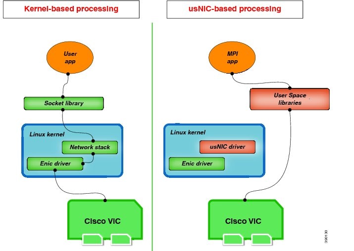
Cisco user-space NIC(Cisco usNIC)機能は、ネットワーキング パケットの送受信時にカーネルをバイパスすることにより、データセンターの Cisco UCS サーバで稼動しているソフトウェア アプリケーションのパフォーマンスを向上させます。アプリケーションは などの Cisco UCS VIC 第 2 世代以降のアダプタと直接やり取りするので、ハイ パフォーマンス コンピューティング クラスタのネットワーキング パフォーマンスが向上します。Cisco usNIC のメリットを享受するには、ソケットやその他の通信 API ではなく、Message Passing Interface(MPI)をアプリケーションで使用する必要があります。
Cisco usNIC を使用すると、MPI アプリケーションで次の利点が得られます。
-
低遅延で、高スループットの通信転送を提供します。
-
標準のアプリケーション非依存イーサネット プロトコルを実行します。
-
次に示すシスコ データセンター プラットフォームで、低遅延の転送、ユニファイド ファブリック、統合管理のサポートを活用します。
標準イーサネット アプリケーションは、Linux カーネルのネットワーキング スタックを呼び出すユーザ領域のソケット ライブラリを使用します。次に、ネットワーキング スタックは Cisco eNIC ドライバを使用して、Cisco VIC ハードウェアと通信します。次の図は、通常のソフトウェア アプリケーションと Cisco usNIC を使用する MPI アプリケーションの対比を示しています。
Cisco IMC GUI を使用した Cisco usNIC の表示および設定
このタスクを実行するには、管理者権限で Cisco IMC GUI にログインする必要があります。このビデオの [再生(Play)] をクリックして、CIMC で Cisco usNIC を設定する方法を視聴します。
| ステップ 1 | Cisco IMC GUI にログインします。
Cisco IMC へのログイン方法に関する詳細については、『Cisco UCS C-Series Servers Integrated Management Controller GUI Configuration Guide』を参照してください。 | ||||||||||||||||||||||||||||||||||||||
| ステップ 2 | [ナビゲーション(Navigation)] ペインの [ネットワーキング(Networking)] メニューをクリックします。 | ||||||||||||||||||||||||||||||||||||||
| ステップ 3 | [アダプタ カード(Adapter Card)] ペインの [vNICs] タブをクリックします。 | ||||||||||||||||||||||||||||||||||||||
| ステップ 4 | [vNICs] ペインの [eth0] または [eth1] をクリックします。 | ||||||||||||||||||||||||||||||||||||||
| ステップ 5 | [イーサネット インターフェイス(Ethernet Interfaces)] 領域で、[usNIC] 領域を選択します。 | ||||||||||||||||||||||||||||||||||||||
| ステップ 6 | [プロパティ(Properties)] 領域で、次のフィールドを確認して更新します。
| ||||||||||||||||||||||||||||||||||||||
| ステップ 7 | [変更の保存(Save Changes)] をクリックします。
変更内容は次のサーバのリブート時に有効になります。 |
usNIC プロパティの表示
| ステップ 1 | [ナビゲーション(Navigation)] ペインの [ネットワーキング(Networking)] メニューをクリックします。 | ||||||||||||||||||||||||||||||||||||||
| ステップ 2 | [アダプタ カード(Adapter Card)] ペインの [vNICs] タブをクリックします。 | ||||||||||||||||||||||||||||||||||||||
| ステップ 3 | [vNICs] ペインの [eth0] または [eth1] をクリックします。 | ||||||||||||||||||||||||||||||||||||||
| ステップ 4 | [ホスト イーサネット インターフェイス(Host Ethernet Interfaces)] ペインの [usNIC プロパティ(usNIC Properties)] 領域で、次のフィールドの情報を確認します。
|
iSCSI ブート機能の設定
vNIC の iSCSI ブート機能の設定
ラック サーバがスタンドアロン モードに設定されていて、VIC アダプタが Nexus 5000 および Nexus 6000 スイッチ ファミリに直接接続されている場合は、iSCSI ストレージ ターゲットからサーバがリモートでブートされるようにこれらの VIC アダプタを設定できます。ラック サーバがリモート iSCSI ターゲット デバイスからホスト OS イメージをロードできるようにイーサネット vNIC を設定できます。
vNIC で iSCSI ブート機能を設定する方法は、次のとおりです。
-
このタスクを実行するには、admin 権限でログインする必要があります。
-
iSCSI ストレージ ターゲットからサーバをリモートでブートするように vNIC を設定するには、vNIC の PXE ブート オプションをイネーブルにする必要があります。
(注) | ホストごとに最大 2 つの iSCSI vNIC を設定できます。 |
vNIC 上の iSCSI ブート機能の設定
ホストごとに最大 2 つの iSCSI vNIC を設定できます。
| ステップ 1 | [ナビゲーション(Navigation)] ペインの [ネットワーキング(Networking)] メニューをクリックします。 | ||||||||||||||||||||||||
| ステップ 2 | [アダプタ カード(Adapter Card)] ペインの [vNICs] タブをクリックします。 | ||||||||||||||||||||||||
| ステップ 3 | [vNICs] ペインの [eth0] または [eth1] をクリックします。 | ||||||||||||||||||||||||
| ステップ 4 | [イーサネット インターフェイス(Ethernet Interfaces)] 領域で、[iSCSI ブート プロパティ(iSCSI Boot Properties)] 領域を選択します。 | ||||||||||||||||||||||||
| ステップ 5 | [全般(General)] 領域で、次のフィールドを更新します。
| ||||||||||||||||||||||||
| ステップ 6 | [イニシエータ(Initiator)] 領域で、次のフィールドを更新します。
| ||||||||||||||||||||||||
| ステップ 7 | [プライマリ ターゲット(Primary Target)] 領域で、次のフィールドを更新します。
| ||||||||||||||||||||||||
| ステップ 8 | [セカンダリ ターゲット(Secondary Target)] 領域で、次のフィールドを更新します。
| ||||||||||||||||||||||||
| ステップ 9 | [変更の保存(Save Changes)] をクリックします。 |
vNIC からの iSCSI ブート設定の除去
このタスクを実行するには、admin 権限でログインする必要があります。
| ステップ 1 | [ナビゲーション(Navigation)] ペインの [ネットワーキング(Networking)] メニューをクリックします。 |
| ステップ 2 | [アダプタ カード(Adapter Card)] ペインの [vNICs] タブをクリックします。 |
| ステップ 3 | [vNICs] ペインの [eth0] または [eth1] をクリックします。 |
| ステップ 4 | [イーサネット インターフェイス(Ethernet Interfaces)] 領域で、[iSCSI ブート プロパティ(iSCSI Boot Properties)] 領域を選択します。 |
| ステップ 5 | 領域下部にある [ISCSI の構成解除(Unconfigure ISCSI)] ボタンをクリックします。 |
アダプタ設定のバックアップと復元
アダプタ設定のエクスポート
アダプタ設定は、次のいずれかになるリモート サーバに XML ファイルとしてエクスポートできます。
リモート サーバの IP アドレスを取得します。
| ステップ 1 | [ナビゲーション(Navigation)] ペインの [ネットワーキング(Networking)] メニューをクリックします。 | ||||||||||||||
| ステップ 2 | [アダプタ カード(Adapter Card)] タブをクリックします。
[全般(General)] タブが表示されます。 | ||||||||||||||
| ステップ 3 | [全般(General)] タブの [アクション(Actions)] 領域で、[エクスポート設定(Export Configuration)] をクリックします。
[アダプタ設定のエクスポート(Export Adapter Configuration)] ダイアログボックスが開きます。 | ||||||||||||||
| ステップ 4 | [アダプタ設定のエクスポート(Export Adapter Configuration)] ダイアログボックスで、次のフィールドを更新します。
| ||||||||||||||
| ステップ 5 | [設定のエクスポート(Export Configuration)] をクリックします。 |
アダプタ設定のインポート
| ステップ 1 | [ナビゲーション(Navigation)] ペインの [ネットワーキング(Networking)] メニューをクリックします。 | ||||||||||||||
| ステップ 2 | [アダプタ カード(Adapter Card)] タブをクリックします。
[全般(General)] タブが表示されます。 | ||||||||||||||
| ステップ 3 | [全般(General)] タブの [アクション(Actions)] 領域で、[インポート設定(Import Configuration)] をクリックします。
[アダプタ設定のインポート(Import Adapter Configuration)] ダイアログボックスが開きます。 | ||||||||||||||
| ステップ 4 | [アダプタ設定のインポート(Import Adapter Configuration)] ダイアログボックスで、次のフィールドを更新します。
| ||||||||||||||
| ステップ 5 | [設定のインポート(Import Configuration)] をクリックします。 アダプタは、指定された IP アドレスの TFTP サーバから、指定されたパスの設定ファイルをダウンロードします。この設定は、サーバが次にリブートされたときにインストールされます。 |
次の作業
サーバをリブートして、インポートした設定を適用します。
アダプタのデフォルトの復元
| ステップ 1 | [ナビゲーション(Navigation)] ペインの [ネットワーキング(Networking)] メニューをクリックします。 | ||
| ステップ 2 | [アダプタ カード(Adapter Card)] タブをクリックします。
[全般(General)] タブが表示されます。 | ||
| ステップ 3 | [全般(General)] タブの [アクション(Actions)] 領域で、[デフォルトにリセット(Reset To Defaults)] をクリックし、[OK] をクリックして確定します。
|
 フィードバック