LED

Switch Chassis LEDs

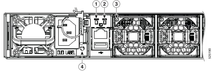
The BCN, STS, ENV, Port, and Lane Select LEDs are located on the left side of the front of the switch. The port LEDs appear as triangles pointing up or down to the nearest port. The Power Supply and Fan Module LEDs are located on the rear of the switch.

1

Lane Indicators

4

Beacon

7

SFP Act/Status

2

Lane Select Button

5

Status

8

Top QSFP port

3

RJ45 Act/Status

6

Environment

9

Bottom QSFP port

LED

Color

Status

BCN

Blue

The operator has activated this LED to identify this switch in the chassis.

Off

This switch is not being identified.

STS

Green

The switch is operational.

Flashing amber

The switch is booting up.

Amber

Temperature exceeds the minor alarm threshold.

Red

Temperature exceeds the major alarm threshold.

Off

The switch is not receiving power.

ENV

Green

Fans and power supply modules are operational.

Amber

At least one fan or power supply module is not operating.

(port)

Green

Port admin state is 'Enabled', SFP is present and the interface is connected (that is, cabled, and the link is up).

Amber

Port admin state is 'Disabled', or the SFP is absent, or both.

Off

Port admin state is 'Enabled' and SFP is present, but interface is not connected.

レーン リンクの LED

レーン リンクの LED は、チェック中のブレークアウト レーンを示します。[レーン選択(Lane Select)] ボタンを使用して、ポート LED に表示するブレークアウト レーン ステータスの数を選択します。レーン リンクの LED がいずれも点灯していない場合は、4 つすべてのレーンがチェック中です。

点灯している LED 説明

Fan Module LEDs

The fan module status LED is located above the air holes on the front of the fan module. Every fan module has an LED.

Table 1. Fan LED

Fan LED

Color

Status Description

Status

OFF

Fan tray is not receiving power

Amber

The fan is inserted into the system and pending to come on-line

Green

Fans are operating normally

Flashing Amber

This fan tray has failed

Figure 1. Cisco N9324C-SE1U Power Side Blowup

1

BCN LED

3

Fan LED

2

STS LED

4

Power Supply LED

電源 LED

電源モジュールの LED は電源モジュールの左右面にあります。OK LED と障害 LED によって示される状態の組み合わせは、次の表に示されるように、モジュールのステータスを表します。

OK LED

FAIL または FAIL/ID LED

ステータス

消灯

電源装置はオンであり、スイッチに給電しています。

グリーンで点滅

消灯

電源モジュールが電源に接続していますが、スイッチに電力が供給されていません。電源モジュールがシャーシに正しく取り付けられていない可能性があります。

消灯

消灯

取り付けられているすべての電源モジュールに電力が供給されていないか、または取り外した電源モジュールに電力が供給されていません。

消灯

オレンジに点滅

電源モジュールは動作していますが、警告状態が発生しています。おそらく次のいずれかの状況にあります。

  • 高温

  • 高電力

  • 電源装置のファンが低速

  • 低電圧

  • 電源モジュールがシャーシに取り付けられていますが、電源から切断されました。

消灯

オレンジに点滅(10 秒)してからオレンジ

電源モジュールが取り付けられていますが、電源に接続していません。

消灯

オレンジ

電源装置の故障:おそらく次のいずれかの状況にあります。

  • 電圧オーバー

  • 過電流

  • 温度過上昇

  • 電源装置ファンの障害

ステータス/説明

緑で点灯

調整時の出力 12V メインおよび 12V スタンバイ

2 Hz 緑で点滅

AC 入力が存在し、動作範囲内/スタンバイモード 12Vstby

4 Hz 緑で点滅

ブートローディングモードの電源

オレンジで点灯

障害(出力なし)、または次のいずれかの状態が考えられます。

  • AC 入力が動作範囲を下回っていますが、パラレルユニットから 12Vstby、

  • 電圧オーバー

  • 過電流

  • 温度過上昇

  • ファン障害による OTP

1 HZ オレンジに点滅

電源モジュールは動作していますが、警告状態が発生しています。おそらく次のいずれかの状況にあります。

  • 高温

  • 高電力

  • ファンの速度低下

消灯

動作範囲を下回る出力または AC 入力はなく、パラレル ユニットからの 12V スタンバイもありません。