ファイアウォールのケーブル接続とオンボード

ファイアウォールをケーブル接続し、Security Cloud Control にオンボードします。

ファイアウォールのケーブル接続

  • コンソールケーブルを入手します。デフォルトではファイアウォールにコンソールケーブルが付属していないため、サードパーティの USB-to-RJ-45 シリアルケーブルなどを購入する必要があります。

  • データ インターフェイス ポートに SFP を取り付けます。組み込みポートは、SFP/SFP+/SFP28 モジュールを必要とする 1/10/25 Gb SFP28 ポートです。

  • 詳細については、ハードウェア設置ガイドを参照してください。

Security Cloud Control のケーブル配線

手動プロビジョニングによるファイアウォールをオンボード

CLI 登録キーを使用してファイアウォールをオンボードします。

手順


ステップ 1

Security Cloud Control のナビゲーションウィンドウで セキュリティデバイス をクリックし、青色のプラスボタン(プラス記号)をクリックしてデバイスを [オンボード(Onboard)] します。

ステップ 2

[FTD] タイルをクリックします。

ステップ 3

[管理モード] で、[FTD] が選択されていることを確認します。

ステップ 4

オンボーディング方法として [CLI登録キーを使用(Use CLI Registration Key)] を選択します。

図 1. CLI 登録キーを使用
CLI 登録キーを使用

ステップ 5

[デバイス名(Device Name)] を入力して、[次へ(Next)] をクリックします。

図 2. デバイス名
Device Name

ステップ 6

[ポリシー割り当て(Policy Assignment)] については、ドロップダウンメニューを使用して、デバイスのアクセス コントロール ポリシーを選択します。ポリシーが設定されていない場合は、[デフォルトのアクセスコントロールポリシー(Default Access Control Policy)] を選択します。

図 3. アクセス コントロール ポリシー
アクセス制御ポリシー

ステップ 7

[サブスクリプションライセンス(Subscription License)] については、[物理 FTD デバイス(Physical FTD Device)] ラジオ ボタンをクリックし、有効にする各機能ライセンスをチェックします。[Next] をクリックします。

図 4. サブスクリプションライセンス
サブスクリプションライセンス

ステップ 8

[CLI登録キー(CLI Registration Key)] については、Security Cloud Control は、登録キーとその他のパラメータを使用してコマンドを生成します。このコマンドをコピーして、Threat Defense の初期設定で使用する必要があります。

図 5. CLI 登録キー
CLI 登録キー

configure manager add Security Cloud Control_hostname registration_key nat_id display_name

スタートアップスクリプトを完了した後、Threat Defense CLI でこのコマンドをコピーします。初期設定:CLI を参照してください。

例:

CLI セットアップのサンプルコマンド:


configure manager add account1.app.us.scc.cisco.com KPOOP0rgWzaHrnj1V5ha2q5Rf8pKFX9E
Lzm1HOynhVUWhXYWz2swmkj2ZWsN3Lb account1.app.us.scc.cisco.com

ステップ 9

オンボーディングウィザードで [次へ(Next)] をクリックして、デバイスの登録を開始します。

ステップ 10

(任意) [セキュリティデバイス(Security Devices)] ページの並べ替えとフィルタ処理に役立つラベルをデバイスに追加します。ラベルを入力し、青いプラスボタン(プラス記号)を選択します。ラベルは、Security Cloud Control への導入準備後にデバイスに適用されます。

図 6. 終了
終了

初期設定:CLI

CLI セットアップスクリプトを使用して、専用の管理 IP アドレス、ゲートウェイ、およびその他の基本ネットワーク設定を行います。

手順


ステップ 1

コンソールポートに接続して Threat Defense CLI にアクセスします。Threat Defense CLI へのアクセスを参照してください。

ステップ 2

管理インターフェイスの設定用の CLI セットアップスクリプトを完了します。

(注)  


設定をクリア(たとえば、イメージを再作成することにより)しないかぎり、CLI セットアップスクリプトを繰り返すことはできません。ただし、これらの設定すべては、後から CLI で configure network コマンドを使用して変更できます。Cisco Secure Firewall Threat Defense コマンドリファレンスを参照してください。


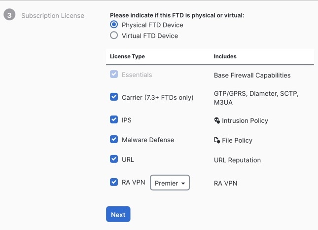
You must accept the EULA to continue.
Press <ENTER> to display the EULA:                 
Cisco General Terms
[...]

Please enter 'YES' or press <ENTER> to AGREE to the EULA:

System initialization in progress.  Please stand by.
You must configure the network to continue.
Configure at least one of IPv4 or IPv6 unless managing via data interfaces.
Do you want to configure IPv4? (y/n) [y]:
Do you want to configure IPv6? (y/n) [y]: n

ガイダンス:これらのタイプのアドレスの少なくとも 1 つについて y を入力します。管理インターフェイスを使用する予定がない場合でも、プライベートアドレスなどの IP アドレスを設定する必要があります。

Configure IPv4 via DHCP or manually? (dhcp/manual) [manual]:

ガイダンス:[手動(manual)] を選択します。マネージャアクセスに外部インターフェイスを使用する場合、DHCP はサポートされません。ルーティングの問題を防ぐために、このインターフェイスがマネージャ アクセス インターフェイスとは異なるサブネット上にあることを確認してください。

Enter an IPv4 address for the management interface [192.168.45.61]: 10.89.5.17
Enter an IPv4 netmask for the management interface [255.255.255.0]: 255.255.255.192
Enter the IPv4 default gateway for the management interface [data-interfaces]:

ガイダンス:ゲートウェイを data-interfaces に設定します。この設定は、外部インターフェイスを通じてルーティングできるように、バックプレーンを介して管理トラフィックを転送します。

Enter a fully qualified hostname for this system [firepower]: 1010-3
Enter a comma-separated list of DNS servers or 'none' [208.67.222.222,208.67.220.220,2620:119:35::35]:
Enter a comma-separated list of search domains or 'none' []: cisco.com
If your networking information has changed, you will need to reconnect.
Disabling IPv6 configuration: management0
Setting DNS servers: 208.67.222.222,208.67.220.220,2620:119:35::35
Setting DNS domains:cisco.com

ガイダンス:管理インターフェイスの DNS サーバーを設定します。これらは、両方とも外部インターフェイスからアクセスされるため、後で設定する外部インターフェイスの DNS サーバーと一致する可能性があります。

Setting hostname as 1010-3
Setting static IPv4: 10.89.5.17 netmask: 255.255.255.192 gateway: data on management0
Updating routing tables, please wait...
All configurations applied to the system. Took 3 Seconds.
Saving a copy of running network configuration to local disk.
For HTTP Proxy configuration, run 'configure network http-proxy'

ガイダンス:routed と入力します。外部マネージャアクセスは、ルーテッド ファイアウォール モードでのみサポートされています。

Configuring firewall mode ...


Device is in OffBox mode - disabling/removing port 443 from iptables.
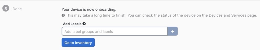
Update policy deployment information
    - add device configuration
    - add network discovery
    - add system policy

You can register the sensor to a Firepower Management Center and use the
Firepower Management Center to manage it. Note that registering the sensor
to a Firepower Management Center disables on-sensor Firepower Services
management capabilities.

When registering the sensor to a Firepower Management Center, a unique
alphanumeric registration key is always required.  In most cases, to register
a sensor to a Firepower Management Center, you must provide the hostname or
the IP address along with the registration key.
'configure manager add [hostname | ip address ] [registration key ]'

However, if the sensor and the Firepower Management Center are separated by a
NAT device, you must enter a unique NAT ID, along with the unique registration
key.
'configure manager add DONTRESOLVE [registration key ] [ NAT ID ]'

Later, using the web interface on the Firepower Management Center, you must
use the same registration key and, if necessary, the same NAT ID when you add
this sensor to the Firepower Management Center.
>

ステップ 3

マネージャアクセス用の外部インターフェイスを設定します。

configure network management-data-interface

その後、外部インターフェイスの基本的なネットワーク設定を行うように求めるプロンプトが表示されます。

手動 IP アドレス


> configure network management-data-interface
Data interface to use for management: ethernet1/1
Specify a name for the interface [outside]: internet
IP address (manual / dhcp) [dhcp]: manual
IPv4/IPv6 address: 10.10.6.7
Netmask/IPv6 Prefix: 255.255.255.0
Default Gateway: 10.10.6.1
Comma-separated list of DNS servers [none]: 208.67.222.222,208.67.220.220

ガイダンス:登録後に外部 DNS サーバーを保持するには、Management Center で DNS プラットフォーム設定を再設定する必要があります。


DDNS server update URL [none]:
Do you wish to clear all the device configuration before applying ? (y/n) [n]:

Configuration done with option to allow manager access from any network, if you wish to change the manager access network
use the 'client' option in the command 'configure network management-data-interface'.

Setting IPv4 network configuration.
Network settings changed.

>

DHCP からの IP アドレス


> configure network management-data-interface
Data interface to use for management: ethernet1/1
Specify a name for the interface [outside]:
IP address (manual / dhcp) [dhcp]:  
DDNS server update URL [none]: https://dwinchester:pa$$w0rd17@domains.example.com/nic/update?hostname=<h>&myip=<a>
Do you wish to clear all the device configuration before applying ? (y/n) [n]:

Configuration done with option to allow manager access from any network, if you wish to change the manager access network 
use the 'client' option in the command 'configure network management-data-interface'.

Setting IPv4 network configuration.
Network settings changed.

> 

ステップ 4

Security Cloud Control が生成した configure manager add コマンドを使用して、この Threat Defense を管理する Security Cloud Control を識別します。コマンドの生成については、手動プロビジョニングによるファイアウォールをオンボード を参照してください。

例:


> configure manager add account1.app.us.cdo.cisco.com KPOOP0rgWzaHrnj1V5ha2q5Rf8pKFX9E
Lzm1HOynhVUWhXYWz2swmkj2ZWsN3Lb account1.app.us.cdo.cisco.com
Manager successfully configured.

ステップ 5

デバイスをリモート支社に送信できるように Threat Defense をシャットダウンします。

システムを適切にシャットダウンすることが重要です。単純に電源プラグを抜いたり、電源スイッチを押したりすると、重大なファイル システムの損傷を引き起こすことがあります。バックグラウンドでは常に多数のプロセスが実行されており、電源プラグを抜いたり、電源を切断したりすると、システムをグレースフルシャットダウンできないことを覚えておいてください。

  1. shutdown コマンドを入力します。

  2. 電源 LED とステータス LED を観察して、シャーシの電源が切断されていることを確認します(LED が消灯)。

  3. シャーシの電源が正常に切断されたら、必要に応じて電源プラグを抜き、シャーシから物理的に電源を取り外すことができます。