ルーテッド モードの設定例
ここでは、次の内容について説明します。
• 「例 1:外部からアクセスのあるマルチモード ファイアウォール」
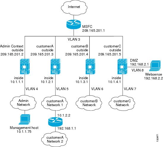
• 「例 2:同じセキュリティ レベルを使用するシングル モード ファイアウォールの例」
• 「例 3:マルチコンテキストの共有リソースの例」
• 「例 4:IPv6 の設定例」
システム コンフィギュレーション(例 1)
まず、 mode multiple コマンドを使用して、マルチコンテキスト モードをイネーブルにします。次に、複数のコンテキストを使用できるように、アクティベーション キーを入力します。モードおよびアクティベーション キーは、再起動後も保持されますが、コンフィギュレーション ファイルには保存されません。 write terminal 、 show startup-config 、または show running-config コマンドを使用してFWSM上で設定を表示すると、FWSMのリリースの次にモードが表示されます(ブランクはシングルモード、<system> はマルチモードのシステム コンフィギュレーション、<context> はマルチモードのコンテキストを意味します)。
enable password chr1cht0n
config-url disk://admin.cfg
description This is the context for customer A
config-url disk://contexta.cfg
description This is the context for customer B
config-url disk://contextb.cfg
description This is the context for customer C
allocate-interface vlan7-vlan8
config-url disk://contextc.cfg
limit-resource rate conns 2000
limit-resource conns 20000
limit-resource rate conns 1000
limit-resource conns 10000
limit-resource rate conns 500
limit-resource conns 5000
admin コンテキスト コンフィギュレーション(例 1)
10.1.1.75 のホストは、SSH を使用してコンテキストにアクセスできます。それには、 crypto key generate コマンドを使用してキーを生成する必要があります。証明書は、フラッシュ メモリに保存されます。
ip address 209.165.201.2 255.255.255.224
ip address 10.1.1.1 255.255.255.0
route outside 0 0 209.165.201.1 1
ssh 10.1.1.75 255.255.255.255 inside
nat (inside) 1 10.1.1.0 255.255.255.0
! This context uses dynamic NAT for inside users that access the outside
global (outside) 1 209.165.201.10-209.165.201.29
! The host at 10.1.1.75 has access to the Websense server in Customer C, and
! it needs a static translation for use in Customer C’s access list
static (inside,outside) 209.165.201.30 10.1.1.75 netmask 255.255.255.255
access-list INTERNET remark -Allows inside hosts to access the outside for any IP traffic
access-list INTERNET extended permit ip any any
access-group INTERNET in interface inside
カスタマー A のコンテキスト コンフィギュレーション(例 1)
ip address 209.165.201.3 255.255.255.224
ip address 10.1.2.1 255.255.255.0
route outside 0 0 209.165.201.1 1
! The Customer A context has a second network behind an inside router that requires a
! static route. All other traffic is handled by the default route pointing to the router.
route inside 192.168.1.0 255.255.255.0 10.1.2.2 1
nat (inside) 1 10.1.2.0 255.255.255.0
! This context uses dynamic PAT for inside users that access that outside. The outside
! interface address is used for the PAT address
global (outside) 1 interface
access-list INTERNET remark -Allows inside hosts to access the outside for any IP traffic
access-list INTERNET extended permit ip any any
access-group INTERNET in interface inside
カスタマー B のコンテキスト コンフィギュレーション(例 1)
ip address 209.165.201.4 255.255.255.224
ip address 10.1.3.1 255.255.255.0
route outside 0 0 209.165.201.1 1
nat (inside) 1 10.1.3.0 255.255.255.0
! This context uses dynamic PAT for inside users that access the outside
global (outside) 1 209.165.201.9 netmask 255.255.255.255
access-list INTERNET remark Inside users only access HTTP and HTTPS servers on the outside
access-list INTERNET extended permit tcp any any eq http
access-list INTERNET extended permit tcp any any eq https
access-group INTERNET in interface inside
カスタマー C のコンテキスト コンフィギュレーション(例 1)
ip address 209.165.201.5 255.255.255.224
ip address 10.1.4.1 255.255.255.0
ip address 192.168.2.1 255.255.255.0
enable password treeh0u$e
route outside 0 0 209.165.201.1 1
url-server (dmz) vendor websense host 192.168.2.2 url-block block 50
filter url http 10.1.4.0 255.255.255.0 0 0
! When inside users access an HTTP server, FWSM consults with a
! Websense server to determine if the traffic is allowed
nat (inside) 1 10.1.4.0 255.255.255.0
! This context uses dynamic NAT for inside users that access the outside
global (outside) 1 209.165.201.9 netmask 255.255.255.255
! A host on the admin context requires access to the Websense server for management using
! pcAnywhere, so the Websense server uses a static translation for its private address
static (dmz,outside) 209.165.201.6 192.168.2.2 netmask 255.255.255.255
access-list INTERNET remark -Allows all inside hosts to access the outside for any IP
access-list INTERNET remark -traffic, but denies them access to the dmz.
access-list INTERNET extended deny ip any 192.168.2.0 255.255.255.0
access-list INTERNET extended permit ip any any
access-group INTERNET in interface inside
access-list MANAGE remark -Allows the management host to use pcAnywhere on the
access-list MANAGE remark -Websense server
access-list MANAGE extended permit tcp host 209.165.201.30 host 209.165.201.6 eq pcanywhere-data
access-list MANAGE extended permit udp host 209.165.201.30 host 209.165.201.6 eq pcanywhere-status
access-group MANAGE in interface outside
access-list WEBSENSE remark -The Websense server needs to access the Websense updater access-list WEBSENSE remark -server on the outside
access-list WEBSENSE extended permit tcp host 192.168.2.2 any eq http
access-group WEBSENSE in interface dmz
スイッチの設定(例 1)
次に、FWSMに関連する Cisco IOS スイッチの設定を示します。
firewall module 8 vlan-group 1
firewall vlan-group 1 3-8
ip address 209.165.201.1 255.255.255.224
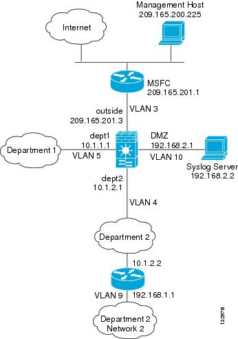
例 2:同じセキュリティ レベルを使用するシングル モード ファイアウォールの例
次の構成では、3 つの内部インターフェイスを作成します。インターフェイスのうちの 2 つは同じセキュリティ レベルの部門に接続します。DMZ インターフェイスは Syslog サーバのホスティングを行います。外部の管理ホストは、Syslog サーバとFWSMにアクセスする必要があります。FWSMとの接続のため、ホストは VPN 接続を使用します。FWSMは、ルートの学習のために、内部インターフェイスの RIP を使用します。FWSMは RIP で学習したルートをアドバタイズしないので、アップストリーム ルータはFWSMトラフィックにスタティック ルートを使用する必要があります(図B-2を参照)。
各部門のネットワークはインターネットへのアクセスを許可され、PAT を使用します。
図B-2 例 2
この構成の詳細については、次の項目を参照してください。
• 「FWSMの設定(例 2)」
• 「スイッチの設定(例 2)」
FWSMの設定(例 2)
ip address 209.165.201.3 255.255.255.224
ip address 10.1.2.1 255.255.255.0
ip address 10.1.1.1 255.255.255.0
ip address 192.168.2.1 255.255.255.0
same-security-traffic permit inter-interface
route outside 0 0 209.165.201.1 1
nat (dept1) 1 10.1.1.0 255.255.255.0
nat (dept2) 1 10.1.2.0 255.255.255.0
! The dept1 and dept2 networks use PAT when accessing the outside
global (outside) 1 209.165.201.9 netmask 255.255.255.255
! Because we perform dynamic NAT on these addresses for outside access, we need to perform
! NAT on them for all other interface access. This identity static statement just
! translates the local address to the same address.
static (dept1,dept2) 10.1.1.0 10.1.1.0 netmask 255.255.255.0
static (dept2,dept1) 10.1.2.0 10.1.2.0 netmask 255.255.255.0
! The syslog server uses a static translation so the outside management host can access
static (dmz,outside) 209.165.201.5 192.168.2.2 netmask 255.255.255.255
access-list DEPTS remark -Allows all dept1 and dept2 hosts to access the
access-list DEPTS remark -outside for any IP traffic
access-list DEPTS extended permit ip any any
access-group DEPTS in interface dept1
access-group DEPTS in interface dept2
access-list MANAGE remark Allows the management host to access the syslog server
access-list MANAGE extended permit tcp host 209.165.200.225 host 209.165.201.5 eq telnet
access-group MANAGE in interface outside
! Advertises the FWSM IP address as the default gateway for the downstream
! router. FWSM does not advertise a default route to the router.
rip dept2 default version 2 authentication md5 scorpius 1
! Listens for RIP updates from the downstream router. FWSM does not
! listen for RIP updates from the router because a default route to the router is all that
rip dept2 passive version 2 authentication md5 scorpius 1
! The client uses a pre-shared key to connect to the FWSM over IPSec. The
! key is the password in the username command following.
isakmp policy 1 authentication pre-share
isakmp policy 1 encryption 3des
crypto ipsec transform-set vpn_client esp-3des esp-sha-hmac
username admin password passw0rd
crypto ipsec transform-set vpn esp-3des esp-sha-hmac
crypto dynamic-map vpn_client 1 set transform-set vpn
crypto map telnet_tunnel 1 ipsec-isakmp dynamic vpn_client
crypto map telnet_tunnel interface outside
ip local pool client_pool 10.1.1.2
access-list VPN_SPLIT extended permit ip host 209.165.201.3 host 10.1.1.2
telnet 10.1.1.2 255.255.255.255 outside
! System messages are sent to the syslog server on the DMZ network
logging host dmz 192.168.2.2
スイッチの設定(例 2)
次に、FWSMに関連するスイッチの設定を示します。
ip address 209.165.201.1 255.255.255.224
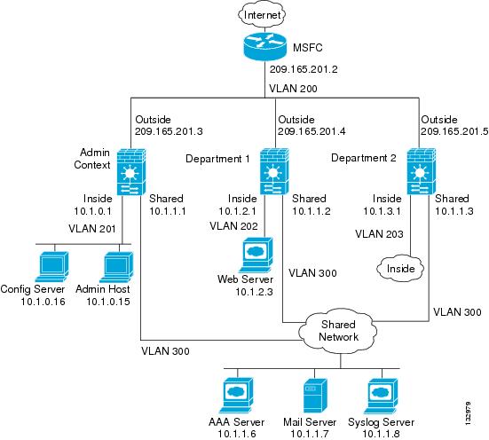
システム コンフィギュレーション(例 3)
まず、 mode multiple コマンドを使用して、マルチコンテキスト モードをイネーブルにします。次に、複数のコンテキストを使用できるように、 activation-key コマンドを使用してアクティベーション キーを入力します。モードおよびアクティベーション キーは、再起動後も保持されますが、コンフィギュレーション ファイルには保存されません。 write terminal 、 show startup-config 、または show running-config コマンドを使用してFWSM上で設定を表示すると、FWSMのリリースの次にモードが表示されます(ブランクはシングルモード、<system> はマルチモードのシステム コンフィギュレーション、<context> はマルチモードのコンテキストを意味します)。
enable password deckard69
allocate-interface vlan200
allocate-interface vlan201
allocate-interface vlan300
config-url disk0://admin.cfg
allocate-interface vlan200
allocate-interface vlan202
allocate-interface vlan300
config-url ftp://admin:passw0rd@10.1.0.16/dept1.cfg
allocate-interface vlan200
allocate-interface vlan203
allocate-interface vlan300
config-url ftp://admin:passw0rd@10.1.0.16/dept2.cfg
admin コンテキスト コンフィギュレーション(例 3)
ip address 209.165.201.3 255.255.255.224
ip address 10.1.0.1 255.255.255.0
ip address 10.1.1.1 255.255.255.0
route outside 0 0 209.165.201.2 1
nat (inside) 1 10.1.0.0 255.255.255.0
! This context uses PAT for inside users that access the outside
global (outside) 1 209.165.201.6 netmask 255.255.255.255
! This context uses PAT for inside users that access the shared network
global (shared) 1 10.1.1.30
! Because this host can access the web server in the Department 1 context, it requires a
static (inside,outside) 209.165.201.7 10.1.0.15 netmask 255.255.255.255
! Because this host has management access to the servers on the Shared interface, it
! requires a static translation to be used in an access list
static (inside,shared) 10.1.1.78 10.1.0.15 netmask 255.255.255.255
access-list INTERNET remark -Allows all inside hosts to access the outside
access-list INTERNET remark -and shared network for any IP traffic
access-list INTERNET extended permit ip any any
access-group INTERNET in interface inside
access-list SHARED remark -Allows only mail traffic from inside to exit shared interface
access-list SHARED remark -but allows the admin host to access any server.
access-list SHARED extended permit ip host 10.1.1.78 any
access-list SHARED extended permit tcp host 10.1.1.30 host 10.1.1.7 eq smtp
! Note that the translated addresses are used.
access-group SHARED out interface shared
! Allows 10.1.0.15 to access the admin context using Telnet. From the admin context, you
! can access all other contexts.
telnet 10.1.0.15 255.255.255.255 inside
aaa-server AAA-SERVER protocol tacacs+
aaa-server AAA-SERVER (shared) host 10.1.1.6
! The host at 10.1.0.15 must authenticate with the AAA server to log in
aaa authentication telnet console AAA-SERVER
! System messages are sent to the syslog server on the Shared network
logging host shared 10.1.1.8
部門 1 のコンテキスト コンフィギュレーション(例 3)
ip address 209.165.201.4 255.255.255.224
ip address 10.1.2.1 255.255.255.0
ip address 10.1.1.2 255.255.255.0
nat (inside) 1 10.1.2.0 255.255.255.0
! The inside network uses PAT when accessing the outside
global (outside) 1 209.165.201.8 netmask 255.255.255.255
! The inside network uses dynamic NAT when accessing the shared network
global (shared) 1 10.1.1.31-10.1.1.37
! The web server can be accessed from outside and requires a static translation
static (inside,outside) 209.165.201.9 10.1.2.3 netmask 255.255.255.255
access-list INTERNET remark -Allows all inside hosts to access the outside
access-list INTERNET remark -and shared network for any IP traffic
access-list INTERNET extended permit ip any any
access-group INTERNET in interface inside
access-list WEBSERVER remark -Allows the management host (its translated address) on the access-list WEBSERVER remark -admin context to access the web server for management
access-list WEBSERVER remark -it can use any IP protocol
access-list WEBSERVER extended permit ip host 209.165.201.7 host 209.165.201.9
access-list WEBSERVER remark -Allows any outside address to access the web server
access-list WEBSERVER extended permit tcp any eq http host 209.165.201.9 eq http
access-group WEBSERVER in interface outside
access-list MAIL remark -Allows only mail traffic from inside to exit out the shared int
! Note that the translated addresses are used.
access-list MAIL extended permit tcp host 10.1.1.31 eq smtp host 10.1.1.7 eq smtp
access-list MAIL extended permit tcp host 10.1.1.32 eq smtp host 10.1.1.7 eq smtp
access-list MAIL extended permit tcp host 10.1.1.33 eq smtp host 10.1.1.7 eq smtp
access-list MAIL extended permit tcp host 10.1.1.34 eq smtp host 10.1.1.7 eq smtp
access-list MAIL extended permit tcp host 10.1.1.35 eq smtp host 10.1.1.7 eq smtp
access-list MAIL extended permit tcp host 10.1.1.36 eq smtp host 10.1.1.7 eq smtp
access-list MAIL extended permit tcp host 10.1.1.37 eq smtp host 10.1.1.7 eq smtp
access-group MAIL out interface shared
aaa-server AAA-SERVER protocol tacacs+
aaa-server AAA-SERVER (shared) host 10.1.1.6
! All traffic matching the WEBSERVER access list must authenticate with the AAA server
aaa authentication match WEBSERVER outside AAA-SERVER
! System messages are sent to the syslog server on the Shared network
logging host shared 10.1.1.8
部門 2 のコンテキスト コンフィギュレーション(例 3)
ip address 209.165.201.5 255.255.255.224
ip address 10.1.3.1 255.255.255.0
ip address 10.1.1.3 255.255.255.0
route outside 0 0 209.165.201.2 1
nat (inside) 1 10.1.3.0 255.255.255.0
! The inside network uses PAT when accessing the outside
global (outside) 1 209.165.201.10 netmask 255.255.255.255
! The inside network uses PAT when accessing the shared network
global (shared) 1 10.1.1.38
access-list INTERNET remark -Allows all inside hosts to access the outside
access-list INTERNET remark -and shared network for any IP traffic
access-list INTERNET extended permit ip any any
access-group INTERNET in interface inside
access-list MAIL remark -Allows only mail traffic from inside to exit out the shared int
access-list MAIL extended permit tcp host 10.1.1.38 host 10.1.1.7 eq smtp
! Note that the translated PAT address is used.
access-group MAIL out interface shared
! System messages are sent to the syslog server on the Shared network
logging host shared 10.1.1.8
スイッチの設定(例 3)
次に、FWSMに関連する Cisco IOS スイッチの設定を示します。
firewall module 6 vlan-group 1
firewall vlan-group 1 200-203,300
ip address 209.165.201.2 255.255.255.224
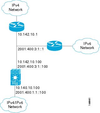
例 4:IPv6 の設定例
次の構成(図B-4を参照)は、FWSM上で設定された IPv6 のいくつかの機能を示しています。
• 各インターフェイスは、IPv6 アドレスと IPv4 アドレスの両方で設定されます。
• IPv6 のデフォルト ルートは ipv6 route コマンドで設定されます。
• IPv6 のアクセス リストは外部インターフェイスに適用されます。
図B-4 例 4:IPv4 と IPv6 のデュアル スタック構成
ip address 10.142.10.100 255.255.255.0
ipv6 address 2001:400:3:1::100/64
ip address 10.140.10.100 255.255.255.0
ipv6 address 2001:400:1:1::100/64
route outside 0.0.0.0 0.0.0.0 10.142.10.1 1
access-list INTERNET remark -Allows all inside IPv4 hosts to access the outside
access-list INTERNET extended permit ip any any
access-group INTERNET in interface inside
ipv6 route outside ::/0 2001:400:3:1::1
ipv6 access-list IPV6INTERNET permit ip any any
access-group IPV6INTERNET in interface inside
ipv6 access-list OUTACL permit icmp6 2001:400:2:1::/64 2001:400:1:1::/64
ipv6 access-list OUTACL permit tcp 2001:400:2:1::/64 2001:400:1:1::/64 eq telnet
ipv6 access-list OUTACL permit tcp 2001:400:2:1::/64 2001:400:1:1::/64 eq ftp
ipv6 access-list OUTACL permit tcp 2001:400:2:1::/64 2001:400:1:1::/64 eq www
access-group OUTACL in interface outside
透過モードでの設定例
ここでは、次の内容について説明します。
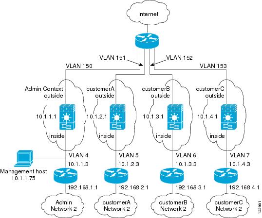
• 「例 5:外部からのアクセスのあるマルチモードの透過ファイアウォールの例」
システム コンフィギュレーション(例 5)
まず、 mode multiple コマンドを使用して、マルチコンテキスト モードをイネーブルにします。モードは、再起動後も保持されますが、コンフィギュレーション ファイルには保存されません。 write terminal 、 show startup-config 、または show running-config コマンドを使用してFWSM上で設定を表示すると、FWSMのリリースの次にモードが表示されます(ブランクはシングルモード、<system> はマルチモードのシステム コンフィギュレーション、<context> はマルチモードのコンテキストを意味します)。
enable password chr1cht0n
allocate-interface vlan150
config-url disk://admin.cfg
description This is the context for customer A
allocate-interface vlan151
config-url disk://contexta.cfg
description This is the context for customer B
allocate-interface vlan152
config-url disk://contextb.cfg
description This is the context for customer C
allocate-interface vlan153
config-url disk://contextc.cfg
limit-resource rate conns 2000
limit-resource conns 20000
limit-resource rate conns 1000
limit-resource conns 10000
limit-resource rate conns 500
limit-resource conns 5000
admin コンテキスト コンフィギュレーション(例 5)
10.1.1.75 のホストは、SSH を使用してコンテキストにアクセスできます。それには、 crypto key generate コマンドを使用してキー のペアを生成する必要があります。
ip address 10.1.1.1 255.255.255.0
route outside 0 0 10.1.1.2 1
ssh 10.1.1.75 255.255.255.255 inside
arp outside 10.1.1.2 0009.7cbe.2100
arp inside 10.1.1.3 0009.7cbe.1000
arp-inspection inside enable flood
arp-inspection outside enable flood
access-list INTERNET remark -Allows all inside hosts to access the outside
access-list INTERNET extended permit ip any any
access-group INTERNET in interface inside
access-list RETURN remark -Allows OSPF back
access-list RETURN extended permit 89 any any
access-list RETURN remark -Allows DHCP back
access-list RETURN extended permit udp any any eq 68
access-group RETURN in interface outside
カスタマー A のコンテキスト コンフィギュレーション(例 5)
ip address 10.1.2.1 255.255.255.0
route outside 0 0 10.1.2.2 1
access-list INTERNET remark -Allows all inside hosts to access the outside
access-list INTERNET extended permit ip any any
access-group INTERNET in interface inside
access-list RETURN remark -Allows OSPF back
access-list RETURN extended permit 89 any any
access-list RETURN remark -Allows DHCP back
access-list RETURN extended permit udp any any eq 68
access-group RETURN in interface outside
カスタマー B のコンテキスト コンフィギュレーション(例 5)
ip address 10.1.3.1 255.255.255.0
route outside 0 0 10.1.3.2 1
access-list INTERNET remark -Allows all inside hosts to access the outside
access-list INTERNET extended permit ip any any
access-group INTERNET in interface inside
access-list RETURN remark -Allows OSPF back
access-list RETURN extended permit 89 any any
access-list RETURN remark -Allows DHCP back
access-list RETURN extended permit udp any any eq 68
access-group RETURN in interface outside
カスタマー C のコンテキスト コンフィギュレーション(例 5)
enable password treeh0u$e
ip address 10.1.4.1 255.255.255.0
route outside 0 0 10.1.4.2 1
access-list INTERNET remark -Allows all inside hosts to access the outside
access-list INTERNET extended permit ip any any
access-group INTERNET in interface inside
access-list RETURN remark -Allows OSPF back
access-list RETURN extended permit 89 any any
access-list RETURN remark -Allows DHCP back
access-list RETURN extended permit udp any any eq 68
access-group RETURN in interface outside
フェールオーバーの設定例
ここでは、次の内容について説明します。
• 「例 6:ルーテッド モードのフェールオーバー」
• 「例 7:透過モードのフェールオーバー」
• 「例 8:非対称ルーティング サポートを使用したアクティブ/アクティブのフェールオーバー」
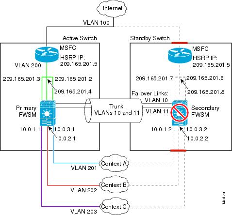
例 6:ルーテッド モードのフェールオーバー
次の構成では、1 台のスイッチにルーテッド モードの各コンテキストを持つマルチコンテキスト モードのFWSM、および 2 台めのスイッチでバックアップとして動作する別のFWSMを示しています(図B-6を参照)。各コンテキスト(A、B、および C)は内部インターフェイスをモニタします。admin コンテキストであるコンテキスト A は、外部インターフェイスもモニタします。外部インターフェイスはすべてのコンテキストの共有インターフェイスなので、1 つのコンテキストでモニタするだけで、すべてのコンテキストをモニタできます。
セカンダリFWSMもマルチコンテキスト モードで、ソフトウェア リリースも同じです。
図B-6 例 6
この構成の詳細については、次の項目を参照してください。
• 「プライマリFWSMの設定(例 6)」
• 「セカンダリ FWSM のシステム コンフィギュレーション(例 6)」
• 「スイッチの設定(例 6)」
システム コンフィギュレーション(プライマリ ユニット ― 例 6)
まず、 mode multiple コマンドを使用して、マルチコンテキスト モードをイネーブルにします。次に、複数のコンテキストを使用できるように、 activation-key コマンドを使用してアクティベーション キーを入力します。モードおよびアクティベーション キーは、再起動後も保持されますが、コンフィギュレーション ファイルには保存されません。 write terminal 、 show startup 、または show running コマンドを使用してFWSM上で設定を表示すると、FWSMのリリースの次にモードが表示されます(ブランクはシングルモード、<system> はマルチモードのシステム コンフィギュレーション、<context> はマルチモードのコンテキストを意味します)。
!The vlan 10 and 11 interfaces are created when you enter the failover lan interface and failover link commands.
description LAN Failover interface
description STATE Failover interface
failover lan interface faillink vlan 10
failover link statelink vlan 11
failover lan unit primary
failover interface ip faillink 192.168.253.1 255.255.255.252 standby 192.168.253.2
failover interface ip statelink 192.168.253.5 255.255.255.252 standby 192.168.253.6
failover interface-policy 50%
failover replication http
allocate-interface vlan200
allocate-interface vlan201
config-url disk://contexta.cfg
allocate-interface vlan200
allocate-interface vlan202
config-url ftp://admin:passw0rd@10.0.3.16/contextb.cfg
allocate-interface vlan200
allocate-interface vlan203
config-url ftp://admin:passw0rd@10.0.3.16/contextc.cfg
コンテキスト A コンフィギュレーション(プライマリ ユニット ― 例 6)
ip address 209.165.201.2 255.255.255.224 standby 209.165.201.6
ip address 10.0.3.1 255.255.255.0 standby 10.0.3.2
monitor-interface outside
nat (inside) 1 0.0.0.0 0.0.0.0 0 0
global (outside) 1 209.165.201.10 netmask 255.255.255.224
! This context uses dynamic PAT for inside users that access the outside
route outside 0 0 209.165.201.5 1
telnet 10.0.3.75 255.255.255.255 inside
access-list INTERNET extended permit ip any any
access-group INTERNET in interface inside
! Allows all inside hosts to access the outside for any IP traffic
コンテキスト B コンフィギュレーション(プライマリ ユニット ― 例 6)
ip address 209.165.201.4 255.255.255.224 standby 209.165.201.8
ip address 10.0.2.1 255.255.255.0 standby 10.0.2.2
nat (inside) 1 0.0.0.0 0.0.0.0 0 0
global (outside) 1 209.165.201.11 netmask 255.255.255.224
! This context uses dynamic PAT for inside users that access the outside
route outside 0 0 209.165.201.5 1
telnet 10.0.2.14 255.255.255.255 inside
access-list INTERNET extended permit ip any any
access-group INTERNET in interface inside
! Allows all inside hosts to access the outside for any IP traffic
コンテキスト C コンフィギュレーション(プライマリ ユニット ― 例 6)
ip address 209.165.201.3 255.255.255.224 standby 209.165.201.7
ip address 10.0.1.1 255.255.255.0 standby 10.0.1.2
nat (inside) 1 0.0.0.0 0.0.0.0 0 0
global (outside) 1 209.165.201.12 netmask 255.255.255.224
! This context uses dynamic PAT for inside users that access the outside
route outside 0 0 209.165.201.5 1
telnet 10.0.1.65 255.255.255.255 inside
access-list INTERNET extended permit ip any any
access-group INTERNET in interface inside
! Allows all inside hosts to access the outside for any IP traffic
セカンダリ FWSM のシステム コンフィギュレーション(例 6)
次の最小限のシステム コンフィギュレーションを行うだけで、コンテキストを設定する必要はありません。
まず、 mode multiple コマンドを使用して、マルチコンテキスト モードをイネーブルにします。次に、複数のコンテキストを使用できるように、 activation-key コマンドを使用してアクティベーション キーを入力します。モードおよびアクティベーション キーは、再起動後も保持されますが、コンフィギュレーション ファイルには保存されません。 write terminal 、 show startup 、または show running コマンドを使用してFWSM上で設定を表示すると、FWSMのリリース ラインの次にモードが表示されます(ブランクはシングルモード、<system> はマルチモードのシステム コンフィギュレーション、<context> はマルチモードのコンテキストを意味します)。
failover lan interface faillink vlan 10
failover interface ip faillink 192.168.253.1 255.255.255.252 standby 192.168.253.2
failover lan unit secondary
スイッチの設定(例 6)
次に、FWSMに関連する両方のスイッチ上の Cisco IOS スイッチの設定を示します。スイッチの冗長設定の詳細については、スイッチのマニュアルを参照してください。
firewall module 1 vlan-group 1
firewall vlan-group 1 10,11,200-203
ip address 209.165.201.1 255.255.255.224
standby 200 ip 209.165.201.5
standby 200 authentication Secret
interface range gigabitethernet 2/1-3
switchport trunk encapsulation dot1q
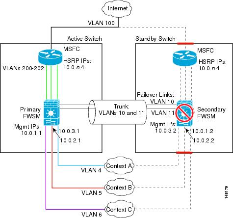
システム コンフィギュレーション(プライマリ ユニット ― 例 7)
まず、 mode multiple コマンドを使用して、マルチコンテキスト モードをイネーブルにします。次に、複数のコンテキストを使用できるように、 activation-key コマンドを使用してアクティベーション キーを入力します。モードおよびアクティベーション キーは、再起動後も保持されますが、コンフィギュレーション ファイルには保存されません。 write terminal 、 show startup 、または show running コマンドを使用してFWSM上で設定を表示すると、FWSMのリリースの次にモードが表示されます(ブランクはシングルモード、<system> はマルチモードのシステム コンフィギュレーション、<context> はマルチモードのコンテキストを意味します)。
!The vlan 10 and 11 interfaces are created when you enter the failover lan interface and failover link commands.
description LAN Failover interface
description STATE Failover interface
failover lan interface faillink vlan 10
failover link statelink vlan 11
failover lan unit primary
failover interface ip faillink 192.168.253.1 255.255.255.252 standby 192.168.253.2
failover interface ip statelink 192.168.253.5 255.255.255.252 standby 192.168.253.6
failover interface-policy 1
failover replication http
allocate-interface vlan200
config-url disk://contexta.cfg
allocate-interface vlan201
config-url ftp://admin:passw0rd@10.0.3.16/contextb.cfg
allocate-interface vlan202
config-url ftp://admin:passw0rd@10.0.3.16/contextc.cfg
コンテキスト A コンフィギュレーション(プライマリ ユニット ― 例 7)
ip address 10.0.3.1 255.255.255.0 standby 10.0.3.2
monitor-interface outside
route outside 0 0 10.0.3.4 1
telnet 10.0.3.75 255.255.255.255 inside
access-list INTERNET remark -Allows all inside hosts to access the outside for
access-list INTERNET remark -any IP traffic
access-list INTERNET extended permit ip any any
access-group INTERNET in interface inside
access-list BPDU ethertype permit bpdu
access-group BPDU in interface inside
access-group BPDU in interface outside
コンテキスト B コンフィギュレーション(プライマリ ユニット ― 例 7)
ip address inside 10.0.2.1 255.255.255.0 standby 10.0.2.2
monitor-interface outside
route outside 0 0 10.0.2.4 1
telnet 10.0.2.14 255.255.255.255 inside
access-list INTERNET remark -Allows all inside hosts to access the outside for
access-list INTERNET remark -any IP traffic
access-list INTERNET extended permit ip any any
access-group INTERNET in interface inside
access-list BPDU ethertype permit bpdu
access-group BPDU in interface inside
access-group BPDU in interface outside
コンテキスト C コンフィギュレーション(プライマリ ユニット ― 例 7)
ip address inside 10.0.1.1 255.255.255.0 standby 10.0.1.2
monitor-interface outside
route outside 0 0 10.0.1.4 1
telnet 10.0.1.65 255.255.255.255 inside
access-list INTERNET remark -Allows all inside hosts to access the outside for
access-list INTERNET remark -any IP traffic
access-list INTERNET extended permit ip any any
access-group INTERNET in interface inside
access-list BPDU ethertype permit bpdu
access-group BPDU in interface inside
access-group BPDU in interface outside
セカンダリ FWSM のシステム コンフィギュレーション(例 7)
次の最小限のシステム コンフィギュレーションを行うだけで、コンテキストを設定する必要はありません。
failover lan interface faillink vlan 10
failover interface ip faillink 192.168.253.1 255.255.255.252 standby 192.168.253.2
failover lan unit secondary
スイッチの設定(例 7)
次に、FWSMに関連する両方のスイッチ上の Cisco IOS スイッチの設定を示します。スイッチの冗長設定の詳細については、スイッチのマニュアルを参照してください。
firewall multiple-vlan-interfaces
firewall module 1 vlan-group 1
firewall vlan-group 1 4-6,10,11,200-202
ip address 10.0.1.3 255.255.255.0
standby 200 authentication Secret
ip address 10.0.2.3 255.255.255.0
standby 200 authentication Secret
ip address 10.0.3.3 255.255.255.0
standby 200 authentication Secret
interface range gigabitethernet 2/1-3
switchport trunk encapsulation dot1q
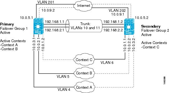
例 8:非対称ルーティング サポートを使用したアクティブ/アクティブのフェールオーバー
次に、アクティブ/アクティブのフェールオーバーを設定する例を示します。この例では、コンテキスト A(admin コンテキスト)、コンテキスト B、コンテキスト C という 3 つのコンテキストが使用されます。
• フェールオーバー グループは、 preempt コマンドで設定されます。
• admin コンテキストが使用するインターフェイスは 1 つのみです。
図B-8に、この例のネットワーク図を示します。
図B-8 アクティブ/アクティブのフェオーバー構成
前提条件
両方のユニットがマルチコンテキスト モードでなければなりません。 mode multiple コマンドを使用して、プライマリとセカンダリのFWSMをマルチコンテキスト モードに切り替えます。 mode multiple コマンドは、プライマリ ユニットとセカンダリ ユニットの両方で入力してモードを変更する必要があります。アクティブ/スタンバイ フェイールオーバー構成の場合でも、 mode multiple コマンドはセカンダリ ユニットにコピーされません。
両方のFWSMには、同じ数のセキュリティ コンテキストのライセンスが必要です。
システム コンテキスト コンフィギュレーション(プライマリFWSM ― 例 8)
システム コンテキストで、フェールオーバー グループと、フェールオーバーおよびステートフル フェールオーバー VLAN が設定されます。
!The vlan 10 and 11 interfaces are created when you enter the failover lan interface and failover link commands.
description LAN Failover interface
description STATE Failover interface
failover lan unit primary
failover lan interface faillink vlan 10
failover link statelink vlan 11
failover interface ip faillink 192.168.1.1 255.255.255.0 standby 192.168.1.2
failover interface ip statelink 192.168.2.1 255.255.255.0 standby 192.168.2.2
description administrative context
config-url disk://contexta.cfg
allocate-interface vlan201
config-url ftp://admin:passw0rd@10.0.3.16/contextb.cfg
allocate-interface vlan202
config-url ftp://admin:passw0rd@10.0.3.16/contextc.cfg
コンテキスト A コンフィギュレーション(プライマリFWSM ― 例 8)
コンテキスト A は admin コンテキストです。この例では、admin コンテキストで 1 つのインターフェイスのみが使用されます。管理アクセス用の内部インターフェイスです。コンテキストで 1 つのインターフェイスしか使用できないため、Telnet を使用してインターネットでFWSMにアクセスすることはできません。コンテキスト内のセキュリティ レベルが最低のインターフェイスには Telnet アクセスは許可されません。また、コンテキスト A には 1 つのインターフェイスしかないため、デフォルトでは最低レベルのインターフェイスとなります。このインターフェイス経由でFWSMを管理するには、SSH 接続を定義する必要があります。
ip address 10.0.3.1 255.255.255.0 standby 10.0.3.2
crypto key generate rsa modulus 1024
ssh 10.0.3.0 255.255.255.0 inside
コンテキスト B コンフィギュレーション(プライマリFWSM ― 例 8)
ip address 10.0.5.1 255.255.255.0 standby 10.0.5.2
ip address 10.0.2.1 255.255.255.0 standby 10.0.2.2
monitor-interface outside
nat (inside) 1 0.0.0.0 0.0.0.0 0 0
global (outside) 1 10.0.5.1 netmask 255.255.255.0
! This context uses dynamic PAT for inside users that access the outside
route outside 0 0 10.0.5.5 1
telnet 10.0.2.14 255.255.255.255 inside
access-list INTERNET extended permit ip any any
access-group INTERNET in interface inside
! Allows all inside hosts to access the outside for any IP traffic
コンテキスト C コンフィギュレーション(プライマリFWSM ― 例 8)
ip address 10.0.9.1 255.255.255.224 standby 10.0.9.2
ip address 10.0.1.1 255.255.255.0 standby 10.0.1.2
monitor-interface outside
nat (inside) 1 0.0.0.0 0.0.0.0 0 0
global (outside) 1 10.0.9.1 netmask 255.255.255.0
! This context uses dynamic PAT for inside users that access the outside
route outside 0 0 10.0.9.5 1
telnet 10.0.1.65 255.255.255.255 inside
access-list INTERNET extended permit ip any any
access-group INTERNET in interface inside
! Allows all inside hosts to access the outside for any IP traffic
セカンダリFWSMの設定(例 8)
フェールオーバー リンクの認識するには、セカンダリFWSMを設定します。セカンダリFWSMは、起動時または failover が最初にイネーブルになったときに、プライマリFWSMからコンテキスト コンフィギュレーションを取得します。フェールオーバー グループの設定内の preempt コマンドを使用すると、設定が同期化されて先行遅延時間が経過したときに、フェールオーバー グループが指定ユニット上でアクティブになります。
プライマリFWSMから設定を受信するには、セカンダリFWSMで failover key コマンドを設定する必要があります。
failover lan unit secondary
failover lan interface faillink vlan 10
failover interface ip faillink 192.168.253.1 255.255.255.252 standby 192.168.253.2
failover コマンドでフェールオーバーをイネーブルにすると、セカンダリFWSMがプライマリFWSMから設定を取得します。
スイッチの設定(例 8)
次に、FWSMに関連する両方のスイッチ上の Cisco IOS スイッチの設定を示します。スイッチの冗長設定の詳細については、スイッチのマニュアルを参照してください。
firewall multiple-vlan-interfaces
firewall module 1 vlan-group 1
firewall vlan-group 1 4-6,10,11,201,202
ip address 10.0.5.3 255.255.255.0
standby 200 authentication Secret
ip address 10.0.9.3 255.255.255.0
standby 200 authentication Secret
interface range gigabitethernet 2/1-3
switchport trunk encapsulation dot1q
 フィードバック