Ultra Cloud Core 5G User Plane Function, Release 2020.02 - Configuration and Administration Guide
Bias-Free Language
The documentation set for this product strives to use bias-free language. For the purposes of this documentation set, bias-free is defined as language that does not imply discrimination based on age, disability, gender, racial identity, ethnic identity, sexual orientation, socioeconomic status, and intersectionality. Exceptions may be present in the documentation due to language that is hardcoded in the user interfaces of the product software, language used based on RFP documentation, or language that is used by a referenced third-party product. Learn more about how Cisco is using Inclusive Language.
The 1:1 UPF Redundancy feature, for 5G deployment, supports the detection of a failed User Plane Function (UPF) and seamlessly
handles the functions of the failed UPF. Each of the Active UPF has a dedicated Standby UPF. The 1:1 UPF Redundancy architecture
is based on the UPF to UPF Interchassis Session Recovery (ICSR) connection.
How it Works
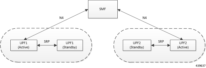
The 5G-UPF deployment leverages the ICSR framework infrastructure for checkpointing and switchover of the UPF node as shown
in the following figure. The Active UPF communicates to its dedicated Standby UPF through the Service Redundancy Protocol
(SRP) link that is provisioned between the UPFs.
Figure 1. UPF 1:1 Redundancy Using SRP
The Session Management Function (SMF) node does not have the Standby UPF information that is available in the UPF group configuration.
Therefore, the SMF is not aware of the UPF redundancy configuration and the switchover event among the UPFs.
The Active UPF communicates to the SMF through the N4 interface address configured in the UPF. The Standby UPF takes over
the same N4 address when it transitions to Active during the switchover event. This implies that the N4 interface is SRP-activated
and is in line with the existing configuration method, therefore UPF switchover is transparent to the SMF.
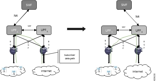
Figure 2. UPF 1:1 Redundancy Switchover
To make redundancy fully compliant, it addresses the following dependencies on the SRP-based ICSR in the 5G environment.
Configuration Synchronization (or, Replica Configuration on Standby UPF)
N4 Association Checkpoint
N4 Link Monitoring
Besides the dependencies listed, the UPF implements data collection and checkpoint procedures specific to the UPF node. For
example, checkpointing for IP-pool chunks. The UPF integrates these procedures into the existing ICSR checkpointing framework.
Independent Configuration of Standby UPF
After UPF is up with base configuration (for example, services, contexts, interfaces, and so on), the rest of the configuration
(for example, ACS and policy-related configuration) is done through Ops-center/Redundancy and Configuration Manager (RCM)
POD. This configuration is common for both SMF/UPF policies. For SRP redundancy to work, the Active and Standby UPF has same
configuration, except SRP-related configuration with which SRP connections are established between Active and Standby UPF.
The RCM configures Active and Standby UPF independently.
BFD Monitor Between Active UP and Standby UP
The Bidirectional Forwarding Detection (BFD) monitors the SRP link between the Active UPF and Standby UPF for a fast failure-detection
and switchover. When the Standby UPF detects a BFD failure in this link, it takes over as the Active UPF.
The BFD link can be single-hop or multi-hop.
To configure the BFD monitor, between the Active UP and Standby UP, see Configuring BFD Monitoring Between Active UPF and Standby UPF.
When SRP VPP monitor is configured, the UPF chassis is SRP Active and if the VPP subsystem fails, then SRP initiates switchover
to Standby UPF. Currently, VPP health monitoring is limited to heartbeat mechanism between NPUMgr task and VPP process.
To configure the VPP monitor, see Configuring VPP Monitor on Active UPF and Standby UPF.
Sx/N4 Association Checkpoint
Whenever an Active UPF initiates an Sx/N4 association to SMF, the Standby UPF checkpoints this data. This maintains the association
information even after the UPF switchover.
The Sx/N4 heartbeat messages are sent and the Active UPF responds back even after back-to-back UPF switchovers.
Sx/N4 Monitor
It is critical to monitor the Sx/N4 interface between the UPF and SMF. The SRP monitoring is enabled on Sx/N4 interface and
the existing Sx/N4 heartbeat mechanism is leveraged to detect the monitor failure. The Sx/N4 module on Active UPF, on detecting
the failure, informs the SRP VPNMgr to trigger UPF switchover event so that the Standby UPF takes over.
Note
Sx/N4 monitoring is available only in the UPF.
It is important to ensure that the SMF Sx/N4 heartbeat timeout is higher than the UPF Sx/N4 heartbeat timeout plus UPF ICSR
switchover time. This is to ensure that the SMF does not detect the Sx/N4 path failure during a UPF switchover because of
the UPF Sx/N4 monitor failure.
The Standby UPF itself has no independent connectivity to the SMF. The Active UPF Sx/N4 context is replicated to the Standby
UPF so that it is ready to takeover during SRP switchover. This implies that when the Active UPF has switched over to Standby
because of Sx/N4 monitor failure, the new Standby has no way of knowing if the UPF to SMF link is working. To prevent a switchback
of the new Standby to Active state again due to Sx/N4 monitor failure in new Active, use the disallow-switchover-on-peer-monitor-fail keyword in the monitor sx CLI command.
After a chassis becomes Standby due to Sx/N4 monitoring failure, the Sx/N4 failure status is not reset even if Sx/N4 up checkpoint
is received from the new Active UPF. This is to prevent the new Active to cause an unplanned switchback again due to Sx/N4
monitor failure when the previous cause of switchover itself was Sx/N4 monitor failure. This prevents back-to-back switchovers
when SMF is down. The Sx/N4 monitor failure status must be manually reset when the operator is convinced that the network
connectivity is normal. To reset, use the new srp reset-sx-fail CLI command (see Resetting Sx/N4 Monitor Failure) in the Standby chassis.
To configure the Sx/N4 monitor, see Configuring Sx/N4 Monitoring on the Active UPF and Standby UPF.
BGP Monitor
Configure BGP peer monitor and peer group monitors for the next-hop routers from UPF (both Gi and Gn side). This is the existing
ICSR configuration. BGP may run with BFD assist to detect fast BGP peer failure.
To configure BGP monitoring and flag BPG monitoring failure, see Configuring BGP Status Monitoring Between Each UP and Next-Hop Router.
UPF Session Checkpoints
The Active chassis sends a collection of UPF data as checkpoints to the peer Standby chassis in the following scenarios:
New call setup
For every state change in the call
Periodically for accounting buckets
On receiving these checkpoints, the Standby chassis acts on the data and updates the necessary information either at the call,
node, or instance level.
VPN IP Pool Checkpoints
During Sx/N4 Association, the IP pool allocated to each of the UPF is sent by SMF to the respective UPF. The VPNMgr receives
this message in the UPF and checkpoints the same information to the Standby UPF when the SRP is configured.
The IP pool information is also sent during the SRP VPNMgr restart and during the SRP link down and up scenarios.
Validation of the presence of IP pool information in the Standby is vital before switchover. If the IP pool information is
not present, then route advertisement is not possible. Therefore, traffic does not reach the UPF.
External Audit and PFD Configuration Audit Interaction
External Audit management is done in Active UPF. The Session Manager gets a start and complete notification of the Configuration
Audit. The Session Manager does not start the External Audit if Configuration Audit is in progress. If the Configuration Audit
start-notification arrives when the External Audit is already underway, then the Session Manager raises a flag such that the
External Audit restarts when it completes. Restarting the External Audit is necessary because it does not achieve its purpose
if it occurs when Configuration Audit is already underway.
Configuring 1:1 UPF Redundancy
The following sections provide information about the CLI commands available in support of the feature.
Configuring BFD Monitoring Between Active UPF and Standby UPF
Use the following configuration to configure Bidirectional Forwarding Detection (BFD) monitoring on the Active UPF and Standby
UPF.
no: Disables BFD monitoring on the Active and Standby UPF.
context context_name : Specifies the context that is used. It refers to the context where the BFD peer is configured (SRP context).
context_name must be an existing context expressed as an alphanumeric string of 1 through 79 characters.
ipv4 _address | ipv6_address: Defines the IP address of the BFD neighbor to be monitored, entered using IPv4 dotted-decimal or IPv6 colon-separated-hexadecimal
notation.
It refers to the IP address of the configured BFD (ICSR) peer.
chassis-to-chassis: BFD runs between primary and backup chassis on non-SRP links.
chassis-to-router: BFD runs between chassis and router.
Caution
Do not use the chassis-to-router keyword for BFD monitoring on the SRP link between the Active UPF and the Standby UPF.
This command is disabled by default.
Configuring BGP Status Monitoring Between Each UP and Next-Hop Router
Use the following commands to configure Border Gateway Protocol (BGP) monitoring between each UP and next-hop router. This
command is configured in the SRP Configuration Mode.
bgp context bgp-session-context-name: Specifies the context where BGP peer is configured. bgp-session-context-name specifies the context string.
nexthop-router-ipv4-address | nexthop-router-ipv6-address: Specifies the configured BGP peer IPv4 or IPv6 address to monitor.
vrf bgp-session-vrf-name: Specifies the BGP VPN Routing and Forwarding (VRF) instance. bgp-session-vrf-name specifies the VRF name.
group group-number : Specifies the BGP peer group where the BGP peer should be included. group-number specifies the group number.
On implementing this keyword, the behavior is as follows:
BGP peer group is up if any BGP peer in that group is up.
Omitting group configuration for a BGP monitor includes that monitor in group 0.
BGP group 0 monitors in a context from an implicit group. Each context forms a separate BGP group 0 implicit monitor group.
BGP monitor is down if any BGP peer group is down.
This command is disabled by default.
Alternate Algorithm to Flag BGP monitoring failure
In this release, an alternate (new) algorithm is introduced to flag BGP monitoring failure.
Use the following commands to flag BGP monitor failure on a single BGP peer (User Plane) failure. This command is configured
in the SRP Configuration Mode.
configurecontext context_nameservice-redundancy-protocol[ no ] monitor bgp exclusive-failover end
NOTES:
no: Disables flagging of BGP monitor failure on a single BGP peer failure.
On implementing the new exclusive-failover keyword, the behavior is as follows:
BGP peer group is Up if any BGP peer in that group is Up.
Including a BGP peer in group 0 is same as making it non-group (omitting group).
BGP monitor is down if any BGP peer group or any non-group BGP peer is down.
This command is disabled by default.
Configuring Sx/N4 Monitoring on the Active UPF and Standby UPF
Use the following configuration to configure Sx/N4 monitoring on the Active UPF and Standby UPF.
no: Disables Sx/N4 monitoring on the Active and Standby UPF.
context context_name : Specifies the context of the Sx/N4 service.
context_name must be an existing context expressed as an alphanumeric string of 1 through 79 characters.
bind-address { ipv4 _address | ipv6_address }: Defines the service IP address of the Sx/N4 service, entered using IPv4 dotted-decimal or IPv6 colon-separated-hexadecimal
notation.
Note
The IP address family of the bind-address and peer-address must be same.
peer-address { ipv4 _address | ipv6_address }: Defines the IP address of the Sx/N4 peer, entered using IPv4 dotted-decimal or IPv6 colon-separated-hexadecimal notation.
It is possible to implement this CLI command multiple times for monitoring multiple Sx/N4 connections.
The Sx/N4 monitor state goes down when any of the monitored Sx/N4 connections are down.
This command is disabled by default.
Configuring VPP Monitor on Active UPF and Standby UPF
Use the following configuration to configure Vector Packet Processing (VPP) monitor to trigger UPF switchover on the Active
UPF if VPP goes down.
configurecontext context_nameservice-redundancy-protocolmonitor system vpp delay-period secondsend
NOTES:
If previously configured, use the no monitor system vpp CLI command to disable VPP monitoring on the Active and Standby UPF.
vpp delay-period seconds : Specifies the delay period in seconds for a switchover, after a VPP failure. seconds must be in the range of 0 through 300.
If the delay period is a value greater than zero (0), then the switchover is initiated after the specified delay period when
VPP fails. The last VPP status notification within the delay period is the final trigger for switchover action. The default
value is 0 seconds, which initiates an immediate switchover.
The need for delay is to address the scenario wherein the VPP is temporarily down and the revival is in process. This implies
that a switchover may not be necessary.
This command is disabled by default.
Preventing User Plane Switchback
Use the following configuration to prevent the switchback of the new Standby UPF to Active state again due to Sx/N4 monitor
failure in the new Active.
configurecontext context_nameservice-redundancy-protocolmonitor sx disallow-switchover-on-peer-monitor-fail timeout seconds end
Use either of the following CLIs to allow switchback of the new Standby UPF to Active state.
no monitor sx disallow-switchover-on-peer-monitor-fail
disallow-switchover-on-peer-monitor-fail timeout seconds : Prevents the switchback of the UPF to Active state when the working status of the UPF to SMF link is unknown.
timeout seconds: Timeout after which the switchback is allowed even if the Sx/N4 failure status is not reset in the Standby peer. The valid
values range from 0 through 2073600 (24 days).
Note
Assigning 0 seconds as the timeout allows unplanned switchover.
If timeout keyword is not specified, the Active chassis waits indefinitely for the Sx/N4 failure status to be reset in the Standby peer.
The default configuration is to allow unplanned switchover due to Sx/N4 monitor failure in all conditions.
Note
Manual planned switchover is allowed irrespective of whether this CLI is configured or not.
Resetting Sx/N4 Monitor Failure
Use the following configuration only on the Standby chassis to reset the Service Redundancy Protocol (SRP) Sx/N4 monitor failure
information. This command is configured in the Exec Mode.
srp reset-sx-fail
Monitoring and Troubleshooting
This section provides information regarding the CLI command available in support of monitoring and troubleshooting the feature.
Show Command(s) and/or Outputs
This section provides information regarding show commands and/or their outputs in support of this feature.
show srp monitor bfd
The output of this CLI command contains the following fields in support of BFD monitor status:
Type:
(A) - Auth. probe
(B) - BGP
(D) - Diameter
(F) - BFD
(E) - EGQC
(C) - Card
(V) - VPP
State:
(I) - Initializing
(U) - Up
(D) - Down
GroupId
IP Addr
Port
Context (VRF Name)
Last Update
show srp monitor bgp
The output of this CLI command contains the following fields in support of BGP monitor status:
Type:
(A) - Auth. probe
(B) - BGP
(D) - Diameter
(F) - BFD
(E) - EGQC
(C) - Card
(V) - VPP
(S) - Sx
State:
(I) - Initializing
(U) - Up
(D) - Down
GroupId
IP Addr
Port
Context (VRF Name)
Last Update
show srp monitor sx
The output of this CLI command contains the following fields in support of Sx/N4 monitor status:
Type:
(A) - Auth. probe
(B) - BGP
(D) - Diameter
(F) - BFD
(E) - EGQC
(C) - Card
(V) – VPP
(S) - SX
State:
(I) - Initializing
(U) - Up
(D) - Down
GroupId
IP Addr
Port
Context (VRF Name)
Last Update
show srp monitor vpp
The output of this CLI command contains the following fields in support of VPP monitor status:


 Feedback