Performance Optimization Support

Feature Summary and Revision History

Summary Data

Table 1. Summary Data

Applicable Products or Functional Area

SMF

Applicable Platforms

SMI

Feature Default Setting

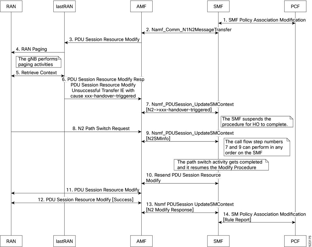
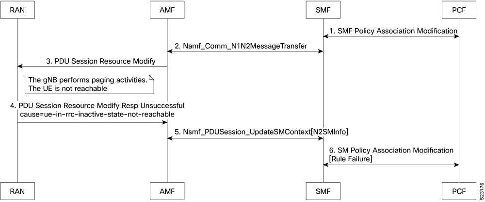
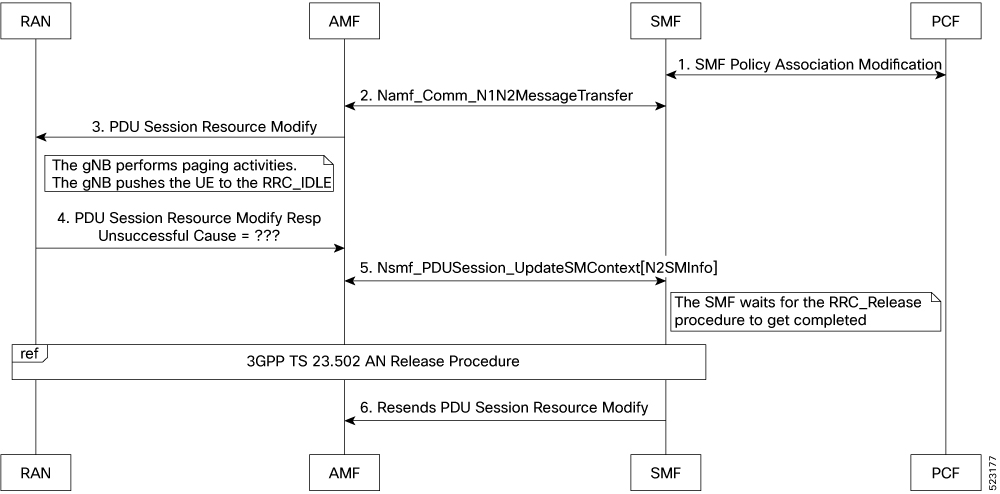
Batch ID Allocation, Release, Reconciliation Support: Disabled – Configuration required to enable

Cache Pod Optimization

CDL Flush Interval and Session Expiration Tuning Configuration: Enabled – Configuration required to disable

Domain-based User Authorization Using Ops Center

Edge Echo Implementation: Enabled – Always-on

Encoder and Decoder Optimization for GTPC Endpoint Pod: Disabled – Configuration required to enable

ETCD Peer Optimization Support: Enabled - Always-on

ETCD Traffic Optimization: Enabled - Always-on

Flag DB Database Updates: Enabled – Always-on

GTPC IPC Cross-rack Support: Disabled – Configuration required to enable

Handling PDU Session Modifications based on RRC Inactive Cause Codes: Disabled – Configuration required to enable

Interservice Pod Communication: Disabled – Configuration required to enable

Resiliency Handling: Disabled – Configuration required to enable

Resiliency Handling: Disabled – Configuration required to enable

Related Documentation

Not Applicable

Revision History

Table 2. Revision History

Revision Details

Release

Added the following support:

  • Cache Pod Optimization

  • Encoder and Decoder Optimization for GTPC Endpoint Pod

  • Flag DB Database Updates

  • Resiliency Handling

2023.01.0

First introduced.

Added the following support:

  • Batch ID Allocation, Release, and Reconciliation Support

  • CDL Flush Interval and Session Expiration Tuning Configuration

  • Domain-based User Authorization Using Ops Center

  • Edge Echo Implementation

  • ETCD Peer Optimization Support

  • GTPC IPC Cross-rack Support

  • Handling PDU Session Modifications based on RRC Inactive Cause Codes

2022.04.0

Feature Description

This chapter describes about the performance optimization features.

Some of the performance optimization features are common across cnSGW-C and SMF.

For complete information on cnSGW-C features, see the UCC 5G cnSGWc Configuration and Administration Guide.

Batch ID Allocation, Release, and Reconciliation Support

Feature Description

This chapter describes about the performance optimization features.

Some of the performance optimization features are common across cnSGW-C and SMF.

For complete information on cnSGW-C features, see the UCC 5G cnSGWc Configuration and Administration Guide.

Feature Configuration

You can enable this feature at run time. By default this feature is disabled.

To configure this feature, use the following sample configuration:

config 
   instance instance-id instance_id 
      endpoint gtp 
      interface s5e 
         enable-direct-encdec true | false 
      interface s11 
         enable-direct-encdec true | false 
      exit 
   exit 

NOTES:

  • enable-direct-encdec true | false : Choose the value as true to enable the encoder and decoder. By default, the value of this field is false .

OAM Support

This use case covers all the Operation, Administration, and Maintenance (OAM) functions of the SMF.

The following features are related to this use case:

Bulk Statistics Support

The following statistics are supported for the Edge Echo Implementation feature:

  • Heartbeat queue status:

    sum(irate(ipc_response_total{rpc_name~=".ipc_stream_hb."}[10s])) by (service_name, 
    instance_id, status, status_code, rpc_name, dest_host)
  • Check the EdgeEcho messages:

    sum(irate(udp_proxy_msg_total{ message_name ="edge_echo"}[30s])) by (message_name, 
    message_direction, status)

To enable the Heartbeat queue and EdgeEcho messages statistics, configure the trace-level statistics for udp_proxy_msg_total using the following:

infra metrics verbose application 
   metrics udp_proxy_msg_total level trace 
   exit 

Note


Enabling the heartbeat and EdgeEcho messages statistics may lead to a performance degradation on the udp-proxy pod.


Cache Pod Optimization

Feature Description

SMF supports the cache pod optimization to reduce the cache pod query at the GTPC endpoint. The get affinity query is used to receive the affinity information in an outgoing request or response message toward the GTPC endpoint. With this optimization, the GTPC endpoint pod doesn't send the query to the cache pod for the upcoming request messages.

CDL Flush Interval and Session Expiration Tuning Configuration

Feature Description

You can modify the default service-pod parameters to fine-tune the throughput performance and optimize the load performance.

Feature Configuration

To configure this feature, use the following configuration:

config 
   profile sgw sgw_name 
      timers [ session-expiration-in-secs session_expiration | affinity-expiration-in-secs affinity_expiration | session-dbsync-interval-in-ms database_sync ] 
      end 

NOTES:

  • session-expiration-in-secs session_expiration —Specify the duration for which the session is cached on service pod. session_expiration accepts value in the range of 1-600 milliseconds. The default value is 30 milliseconds.

  • affinity-expiration-in-secs affinity_expiration —Specify the duration for which the session affinity keys are valid on the service pod and other pods. affinity_expiration accepts value in the range of 1-1200 seconds. The default value is 80 seconds.

  • session-dbsync-interval-in-ms database_sync —Specify the duration after which the session is synchronized in the database. database_sync accepts value in the range of 1-10000 milliseconds. The default value is 500 milliseconds.

Domain-based User Authorization Using Ops Center

Feature Description

SMF and cnSGW-C support domain-based user authorization using the Ops Center. To control the access on a per-user basis, use the TACACS protocol in Ops Center AAA. This protocol provides centralized validation of users who attempt to gain access to a router or NAS.

Configure the NETCONF Access Control (NACM) rules in the rule list. Then, map these rules in the Ops center configuration to map the group to appropriate operational authorization. Use the configurations that are based on the following criteria and products:

  • With the NACM rules and SMF domain-based group, configure the Ops center to allow only access or update SMF-based configuration.

  • With the NACM rules and cSGW-C domain-based group, configure the Ops center to allow only access or update cSGW-C-based configuration.

  • With the NACM rules and cSGW-C domain-based group, configure the Ops center to allow only access or update CCG-based configuration.


Note


The NSO service account can access the entire configuration.


How it Works

To support this feature configuration in Ops Center, the domain-based-services configuration is added in the TACACS security configuration. The TACACS flow change works in the following way:

  • If you have configured the domain-based-services parameter, then the configured user name that is sent to the TACACS process, splits user ID into user ID and domain. The split character, which is a domain delimiter, is configured in domain-based-services. These split characters can be "@", "/", or "\" and are used in the following format to get the domain and user ID information.

    • @ — <user id>@<domain>

    • / — <domain>/<user id>

    • \ — <domain>\<user id>

  • The TACACS authenticates and authorizes as per the existing flow. However, if the domain-based-services feature is enabled and TACACS authenticates and authorizes the user, following steps are added to the TACACS flow procedure.

    • If Network Services Orchestrator (NSO) logs in as the NSO service account, then that session receives a specific NACM group that you configured in domain-based-services nso-service-account group group-name . This functionally is the same as the way NSO works.

    • If the specified domain exists in the group mapping, then the NACM group that you configured in domain-based-services domain-service domain group group-name is applied.

    • If the user does not have a domain or the domain does not exist in the domain to group mapping, then no-domain NACM group that you configured in domain-based-services no-domain group group-name is applied. If the no-domain configuration does not exist, then the user value is rejected.

To enable this feature, you must configure the domain-based-services CLI command with the following options:

  • NSO service account

  • Domain service

  • Domain delimiter

  • No domain

Feature Configuration

To enable domain-based user authorization using Ops Center, use the following sample configuration:

config 
   tacacs-security domain-based-services [ domain-delimiter delimiter_option | domain-service domain_service_name [ group service_group_name  ] | no-domain group service_group_name | nso-service-account [ group service_group_name | id service_account_id ] ] 
   end 

NOTES:

  • domain-based-services [ domain-delimiter delimiter_option | domain-service domain_service_name [ group service_group_name ] | no-domain group service_group_name | nso-service-account [ group service_group_name | id service_account_id ] ] : Configure the required domain-based-services value. The domain-based-services includes the following options:

    • domain-delimiter : Specify the delimiter to use to determine domain. This option is mandatory and allows the following values:

      • @—If domain-delimiter is "@", the user value is in the format: <user>@<domain>.

      • /—If domain-delimiter is "/", the user value is in the format: <domain>/<user>.

      • \—If domain-delimiter is "\", the user value is in the format: <domain>\<user>.

    • domain-service : Specify the list of domains and their group mapping. The key is the name of the domain and group is the group that is assigned to the domain. You must configure at least one option in this list.

    • no-domain : Specify the group that has no domain or if the domain is unavailable in the domain-service mapping, then this group is sent in the accept response.

    • nso-service-account : Specify the NSO service account that has the ID and group. If you configure this parameter, then you must configure the ID and group fields. The ID and group must have string values.

Configuration Example

The following is an example of the domain-based user authorization in the tacacs-security mode:

config
   tacacs-security domain-based-services nso-service-account id nsid
      tacacs-security domain-based-services nso-service-account group nso-group
   tacacs-security domain-based-services no-domain group read-operational
   tacacs-security domain-based-services domain-delimiter @
   tacacs-security domain-based-services domain-service etcd
      group etcd
exit
tacacs-security domain-based-services domain-service sgw
   group sgw_1
exit
tacacs-security domain-based-services domain-service smf
   group smf
exit

Configuration Verification

To verify the configuration, use the following show command:

show running-config tacacs-security

The output of this show command displays all the configurations of the domain-based services within the TACACS security.

[smf] smf# show running-config tacacs-security
tacacs-security service smf
tacacs-security server 1
address 209.165.200.234
key $8$+twbdL2ZCgmjVswgp7kFJp8+SMXDjQRTZgoPVa3oEwY=
exit
tacacs-security domain-based-services nso-service-account id nsid
tacacs-security domain-based-services nso-service-account group nso-group
tacacs-security domain-based-services no-domain group read-operational
tacacs-security domain-based-services domain-delimiter @
tacacs-security domain-based-services domain-service etcd 
group etcd
exit
tacacs-security domain-based-services domain-service sgw
group sgw_1
exit
tacacs-security domain-based-services domain-service smf
group smf
exit

Edge Echo Implementation

Feature Description

In a nonmerged mode, the udp-proxy pod acts as an endpoint, and the gtpc-ep responds to the Echo Requests from the peer node.

The gtpc-ep experiences traffic when the system receives a high number of inputs CEPS leading to a discrepancy between the rate at which gtpc-ep picks up the messages from udp-proxy and the rate at which udp-proxy gets the messages.

If the gtpc-ep is loaded, the queue between the udp-proxy and gtpc-ep gets full, and some of the messages at udp-proxy might get dropped. The peer detects path failure if these are Echo Request messages because an Echo Response is not received. Further, the peer clears all the sessions sent to the sgw-service.

How it Works

This section describes how this feature works.

Nodemgr processes the Echo Request in the following steps:

  • The nodemgr preserves a self-restart counter cache for each GR instance ID and the GTPC peer.

  • When the udp-proxy pod receives an Echo Request from a peer and the self-restart counter value is not available in the self-restart counter cache, the udp-proxy pod forwards the Echo Request to gtpc-ep.

  • The gtpc-ep sends the self-restart counter as part of the UDP proxy message metadata in the Echo Response. The udp-proxy stores the self-restart counter in the self-restart counter cache. When the udp-proxy receives an Echo Request from a peer, and a self-restart counter value is available in the self-restart counter cache, the udp-proxy sends an Echo Response with the restart counter.

  • The udp-proxy forwards the Echo Request message to the gtpc-ep. The gtpc-ep processes the Echo Request and forwards it to nodemgr, if necessary.

  • If the peer restart counter value is modified, the nodemgr detects a path failure.

  • In the Echo Response, the gtpc-ep sends the self-restart counter in the UDP Proxy Message metadata to the udp-proxy. If the self-restart counter differs from the counter that is stored in the self-restart counter cache, the udp-proxy updates the self-restart counter in the cache and drops the Echo Response received from the gtpc-ep.


Note


The Edge Echo feature is not supported when the gtpc-ep is started in the merged mode.


Heartbeat

To handle the Echo Request and Echo Response messages for the GTPV2 interface, a heartbeat queue is implemented between the gtpc-ep and the udp-proxy pod. The heartbeat queue is responsible for handling the HeartBeat Request and HeartBeat Response Messages between the protocol and udp-proxy pod for the PFCP interface.

OAM Support

This section describes operations, administration, and maintenance support for this feature.

Bulk Statistics Support

The following statistics are supported for the Edge Echo Implementation feature:

  • Heartbeat queue status:

    sum(irate(ipc_response_total{rpc_name~=".ipc_stream_hb."}[10s])) by (service_name, 
    instance_id, status, status_code, rpc_name, dest_host)
  • Check the EdgeEcho messages:

    sum(irate(udp_proxy_msg_total{ message_name ="edge_echo"}[30s])) by (message_name, 
    message_direction, status)

To enable the Heartbeat queue and EdgeEcho messages statistics, configure the trace-level statistics for udp_proxy_msg_total using the following:

infra metrics verbose application 
   metrics udp_proxy_msg_total level trace 
   exit 

Note


Enabling the heartbeat and EdgeEcho messages statistics may lead to a performance degradation on the udp-proxy pod.


Encoder and Decoder Optimization for GTPC Endpoint Pod

Feature Description

SMF uses the enable-direct-encdec CLI command to optimize the encoding and decoding of the IEs that are associated with the GTPC endpoint pod. This optimization improves the memory management and reduces the garbage collection time.

Feature Configuration

You can enable this feature at run time. By default this feature is disabled.

To configure this feature, use the following sample configuration:

config 
   instance instance-id instance_id 
      endpoint gtp 
      interface s5e 
         enable-direct-encdec true | false 
      interface s11 
         enable-direct-encdec true | false 
      exit 
   exit 

NOTES:

  • enable-direct-encdec true | false : Choose the value as true to enable the encoder and decoder. By default, the value of this field is false .

ETCD Peer Optimization Support

Feature Description

When large numbers of GTPC peers are connected with SMF or cnSGW-C, the performance of ETCD is impacted. Each peer is a considered as a record in the ETCD, and the timestamp is updated every 30 seconds for each peer. This causes continuous updates on ETCD and generates huge traffic that impacts the overall system performance.

The ETCD Peer Optimization feature facilitates optimization in peer management and enables reduced performance impact on ETCD.

How it Works

This section describes how this feature works.

Instead of considering each peer as an ETCD record entry, several peers are grouped as a peer group based on the hash value of the IP address of each peer. This reduces the number of entries in ETCD. By default, a maximum of 200 peer groups can be created. For any changes related to a peer in a peer group:

  • For a new peer, the peer group is persisted immediately in ETCD.

  • For the change in timestamp for existing peers, the peer group is updated once every 3 seconds. This update:

    • Results in a cumulative group update for many peers that have undergone timestamp change within each peer group.

    • Reduces frequent updates to ETCD.

Flag DB Database Updates

Feature Description

SMF updates the CDL when the subscriber state changes from idle to active, and when the ULI, UeTz, or the serving network is modified.

When the transaction requests driven to CDL increases, SMF incurs a higher CPU utilization. To prevent the needless CPU utilization, SMF updates only a subset of the CDL with the changed attributes.

Flag DB database is updated for the following SMF procedures:

  • MBR with only ULI change—SMF handles MBR with only ULI change, in a stateless way to send the response. After sending the response, the smf-service updates the CDL, which impacts the CPU utilization. To optimize the CPU usage, SMF notifies the CDL about the ULI only with the partial updates.

  • 4G RAT Handover—During an inter S-GW handover, the smf-service receives the MBR with a ULI change and the TEID change. To optimize the CPU usage, SMF notifies the CDL about peer TEID and ULI only with the partial updates, if the handover is successful for all the bearers.

  • N2 Handover—When the N2 handover procedure ends, the smf-service updates the CDL which impacts the CPU utilization. To optimize the CPU usage, the SMF notifies the CDL about only the ULI and TEID with the partial updates, if the handover is successful for all the existing QFI.

Handling PDU Session Modifications based on RRC Inactive Cause Codes

Feature Summary and Revision History

Summary Data

Table 3. Summary Data

Applicable Products or Functional Area

SMF

Applicable Platforms

SMI

Feature Default Setting

Handling PDU Session Modifications based on RRC Inactive Cause Codes:

Disabled – Configuration required to enable

Related Changes in this Release

Not Applicable

Related Documentation

UCC 5G SMF Configuration and Administration Guide

Not Applicable

Revision History

Table 4. Revision History

Revision Details

Release

Support for the following sub-feature was introduced:

Handling PDU Session Modifications based on RRC Inactive Cause Codes

CDETS ID: CSCwb13529

2022.04.0

First introduced.

2021.02.3

Feature Description

The Radio Resource Control (RRC) is a layer within the 5G NR protocol stack. It exists only in the control plane, in the UE, and in the gNB. The existing state of PDU sessions controls the behaviour and functions of the RRC.

During the PCF-initiated modification, the AMF sends those received unsuccessful transfer radio networks cause codes in the N2 content of the SmContextUpdate message to the SMF under the following conditions:

  • When the Xn-handover is in progress.

  • When the AN is released.

  • When the UE is in the RRC inactive state.

  • When the UE isn’t reachable.

The SmContextUpdate message with the N2 cause codes acts as a bridge and converter from AMF to SMF or from SMF to AMF.

How it Works

This section describes how this feature works.

During the PCF-initiated modification, when the Xn-handover is in progress, the following scenarios are noted:

  • The AN gets released or the UE is in RRC inactive state and not reachable.

  • The AMF relays the received unsuccessful transfer radio network cause code, in the N2 content of the SmContextUpdate message to SMF.

  • These cause codes could be standard radio network causes or there could be some customized radio network cause codes being sent from the gNB.

Previously, these cause codes were rejected by the SMF and the PCF was attempting multiple times the same PCF modifications. Now, the SMF doesn't reject immediately, and behaves differently for different cause codes, based on the new N2 trigger configuration to avoid multiple reattempts from the PCF.

The following scenarios are supported in the SMF for the PDU Modify procedure, based on the received N2 cause code:

  • When the cause code indicates that the Xn-handover is in progress or the AN gets released, then the following activities occur:

    • The SMF suspends the ongoing PDU session modification.

    • It resumes back after the Xn-handover or the AN Release.

  • When the cause code indicates that the UE is RRC inactive and not reachable, then the following activities occur:

    • The SMF rejects the PDU session modification.

    • It reports the rule failure to the PCF.

By default, this feature gets activated for a few standard RRC inactive cause codes with default guard timeout and zero max-retry.

For the following cause codes, the SMF suspends session modification, and resumes only after the Xn-handover activity gets over:

  • _RadioNetwork_NG_intra_system_handover_triggered

  • _RadioNetwork_NG_inter_system_handover_triggered

For the following cause codes, the SMF rejects the session modification:

  • _RadioNetwork_UE_in_RRC_INACTIVE_state_not_reachable

Along with the standard cause codes, a new N2 trigger CLI is introduced to configure the different customized radio network cause codes, and the corresponding SMF actions.


Note


The non-roaming PCF-initiated modification scenarios are supported as a part of this feature.


Call Flows

This section describes the key call flows for this feature.

Modifications for PCF-initiated gNB Transfer State

This section describes about the gNB transfer state activities in the PCF-initiated modifications call flow procedure.

The following figure describes Modifications for PCF-initiated gNB Transfer State call flow.

Figure 1. Call Flow for the Modifications for PCF-initiated gNB Transfer State
Table 5. Call Flow Description for the Modifications for PCF-initiated gNB Transfer State

Step

Description

1

The PCF sends the SMF Policy Association Modification Request to the SMF.

It’s an interchangeable action as it also receives the same message from the SMF.

2

The SMF sends the Namf Comm N1N2MessageTransfer Request to the AMF.

It’s an interchangeable action as it also receives the same message from the AMF.

3

The AMF sends the PDU Session Resource Modify Request to the lastRAN.

4

The lastRAN requests the RAN for paging activities.

5

The gNB performs the paging activities and retrieves the context between the RAN and the lastRAN.

The lastRAN sends the Retrieve Context message to the RAN.

It’s an interchangeable action as it also receives the same message from the RAN.

6

The lastRAN sends the PDU Session Resource Modify Response to the AMF.

It also includes the PDU Session Resource Modify Unsuccessful Transfer IE with cause xxx-handover-triggered message.

7

The AMF processes and sends the Nsmf PDUSession UpdateSMContext message (N2 to xxx-handover-triggered) to the SMF.

It’s an interchangeable action as it also receives the same message from the SMF.

Note


During this step, the SMF suspends the further procedure and initiates the HO to complete it.

8

The RAN sends the N2 Path switch Request to the AMF.

9

The AMF sends the Nsmf PDUSession UpdateSMContext (N2SMlnfo) response message to the SMF.

Note


The steps number 7 and 9 can proceed in any order towards the SMF or from the AMF.

10

The SMF resends the PDU Session Resource Modify message to the AMF.

It’s an interchangeable action as it also receives the same message from the AMF.

Note


During this step, the path switch gets completed and it resumes the modify procedure.

11

The AMF sends the PDU Session Resource Modify message to the RAN.

It’s an interchangeable action as it also receives the same message from the RAN.

12

The RAN sends the success note PDU Session Resource Modify (success) message to the AMF.

It’s an interchangeable action as it also receives the same message from the AMF.

13

The AMF sends the modified response Nsmf PDUSession UpdateSMContext (N2 modify response) message to the SMF.

It’s an interchangeable action as it also receives the same message from the AMF.

14

The SMF sends the report SM Policy Association Modification (rule report) message to the PCF.

It’s an interchangeable action as it also receives the same message from the PCF.

Modifications for PCF-initiated UE Not Reachable State

This section describes about the UE not reachable state activities in the PCF-initiated modification call flow procedure.

The following figure describes the Modifications for PCF-initiated UE Not Reachable State.

Figure 2. Call Flow for the Modifications for PCF-initiated UE Not Reachable State
Table 6. Call Flow Description for the Modifications for PCF-initiated UE Not Reachable State

Step

Description

1

The PCF sends the SMF Policy Association Modification Request to the SMF.

It’s an interchangeable action as it also receives the same message from the SMF.

2

The SMF sends the Namf Comm N1N2MessageTransfer Request to the AMF.

It’s an interchangeable action as it also receives the same message from the AMF.

3

The AMF sends the PDU Session Resource Modify Request to the RAN.

Note


During this step, the gNB performs the paging activities as the UE isn’t reachable.

4

The RAN sends the PDU Session Resource Modify Response Unsuccessful message to the AMF.

It also includes the failure cause ue-in-rrc-inactive-state-not-reachable message.

5

The AMF sends the Nsmf PDUSession UpdateSMContext (N2SMlnfo) response message to the SMF.

It’s an interchangeable action as it also receives the same message from the SMF.

6

The SMF sends the failed report SM Policy Association Modification (rule failure report) message to the PCF.

It’s an interchangeable action as it also receives the same message from the PCF.

Modifications for PCF-initiated Inactive to Idle State

This section describes about the inactive to idle state activities in the PCF-initiated modification call flow procedure.

The following figure describes the Modifications for PCF-initiated Inactive to Idle State call flow.

Figure 3. Call Flow for the Modifications for PCF-initiated Inactive to Idle State
Table 7. Call Flow Description for the Modifications for PCF-initiated Inactive to Idle State

Step

Description

1

The PCF sends the SMF Policy Association Modification Request to the SMF.

It’s an interchangeable action as it also receives the same message from the SMF.

2

The SMF sends the Namf Comm N1N2MessageTransfer Request to the AMF.

It’s an interchangeable action as it also receives the same message from the AMF.

3

The AMF sends the PDU Session Resource Modify Request to the RAN.

Note


During this step, the gNB performs the paging activities as the gNB pushes the UE to the RRC_IDLE mode.

4

The RAN sends the PDU Session Resource Modify Response Unsuccessful message to the AMF.

It also includes the unknown failure cause message.

5

The AMF sends the Nsmf PDUSession UpdateSMContext (N2SMlnfo) response message to the SMF.

It’s an interchangeable action as it also receives the same message from the SMF.

Note


During this step, the SMF waits for the RRC_Release procedure to get completed.

6

The SMF resends the PDU Session Resource Modify message to the AMF.

Note


This step follows the 3GPP TS 23.502 AN release procedure.

Feature Configuration

To configure this feature, use the following sample configuration:

config 
profile access access_profile_name 
    n2 trigger { ho-in-progress | temp-not-reachable } { guard-timeout timeout | max-retry retry_count | value retry_count_range } 
    n2 trigger ue-not-reachable value notreachable_count_range 
    end 

NOTES:

  • profile access access_profile_name —Specify a name for the access profile.

  • n2 trigger —Specify the N2 trigger type. Trigger can be the traffic type. Must be one of the following:

    • ho-in-progress —Specify the handover-in-progress trigger configuration list of cause-codes.

    • temp-not-reachable —Specify the temporary not reachable trigger configuration list of cause-codes.

    • ue-not-reachable —Specify the UE not reachable trigger configuration list of cause-codes.

  • guard-timeout timeout —Specify the Handover in progress guard timeout in milliseconds, within the range of 500-30000 milliseconds. The default value is 10000 milliseconds.

  • max-retry retry_count —Specify the maximum retry count value for the handover in progress or temporary not reachable options, within the range of 0-64. The default value is 0.

  • value { notreachable_count_range } | { retry_count_range } —The numbered value in the range of counts for UE not reachable or the maximum retry range.


Note


The defined configurations are used to match the received unsuccessful transfer (radio network standard and customized) causing the code to decide the RRC inactive action. It has the following scenarios:

  • The PCF-initiated modification gets rejected in the case of ue-not-reachable , ho-in-progress , and temp-not-reachable cases. It gets suspended and resumes back after the xn-handover activities in the AN release.

  • The Guard Timer gets started, when the RRC inactive action is either in the ho-in-progress or the temp-not-reachable trigger profile. It waits for the ongoing PCF-initiated modification to suspend. It restarts the xn-handover activities in the AN release within the given time. If this action fails, then the PCF-initiated modification gets rejected. As a result, this action reported as the rule failure note to the PCF.

  • The maximum retry allows the maximum continuous reattempt after the first attempt gets failed. It's a result of receiving the same trigger category cause code repeatedly for each and every attempt. If this action fails, the PCF-initiated modification gets rejected. As a result, this action reported as the rule failure note to the PCF, after reaching the maximum retry attempt.

  • This feature gets activated for the standard RRC inactive cause codes with a default guard timeout and zero maximum-retry.


Configuration Example

The following is an example configuration.

config
smf(config)# profile access access1
 smf(config-access-access1)# n2 trigger [ ho-in-progress | temp-not-reachable ] [ value 1 ] [ guard-timeout 10000 ] [ max-retry 10 ]
 smf(config-access-access1)# n2 trigger ue-not-reachable value [10]
 exit
exit

Configuration Verification

To verify the configuration:

[smf] smf# show running-config profile access access1 n2
profile access access1
  n2 trigger ho-in-progress value [ 50 51 52 53 ] guard-timeout 12000 max-retry 3
  n2 trigger temp-not-reachable value [ 54 55 56 57 ] guard-timeout 11000 max-retry 2
  n2 trigger ue-not-reachable value [ 58 59 60 61 ] 
exit

Resiliency Handling

Feature Description

The Resiliency Handling feature introduces a CLI-controlled framework to support the service pod recovery, when you observe a system fault or a reported crash. It helps in recovering one of the following service pods:

  • sgw-service pod

  • smf-service pod

  • gtpc-ep pod

  • protocol pod

These service pods are software modules containing the logic to handle several session messages. The service pods are fault-prone due to any one of the following or a combination of multiple scenarios:

  • Complex call flow and collision handling

  • Inconsistent session state

  • Incorrect processing of inbound messages against the session state

  • Unexpected and unhandled content in the inbound messages

Whenever you observe the system fault or a crash, the fault behavior results into a forced restart of the service pod. It impacts the ongoing transaction processing of other sessions. The crash reoccurs even after the pod restart.

To mitigate this risk, use the CLI-based framework with actions defined to clean up subscriber sessions or terminate the current processing.

How it Works

This section describes how you can use the fault recovery framework to define actions for the crash. The framework allows you to define any of the following actions:

  • Terminate—When a fault occurs, this action terminates the faulty transactions, and clears the subscriber session cache. It’s applicable for smf-service and sgw-service pods.


    Note


    The pod doesn't get restarted. The database doesn't get cleared during this action.


  • Cleanup—When a fault occurs, this action clears the faulty subscriber session and releases the call. It’s applicable for smf-service and sgw-service pods.

  • Graceful reload—When a fault occurs, this action restarts the pod. It’s applicable for gtpc-ep and protocol pods. It handles the fault signals to clean up resources, such as the keepalive port and closes it early. It also allows the checkport script to detect the protocol pod state and initiates the PFCP VIP switch processing.

  • Reload—When the pod crashes, it initiates the reloading activity. It’s a default setting or value applicable for all the pods.

Feature Configuration

To configure this feature and to enable the system fault recovery, use the following sample configuration:

config 
    system-diagnostics { gtp | pfcp | service | sgw-service } 
        fault 
            action { abort | cleanup { file-detail | interval | num | skip { ims | emergency | wps } } | graceful-Reload | reload } 
            end 

NOTES:

  • system-diagnostics { gtp | pfcp | service | sgw-service } —Specify the required type of service pods for system diagnostics. The available pod options are gtp, pfcp, smf-service, and sgw-service.

  • fault —Enables fault recovery while processing sessions.

  • action { abort | cleanup | graceful-Reload | reload } —Specify one of the following actions to take on fault occurrence. The default action is reload.

    • abort —Deletes the faulty transaction and clears its session cache. The database doesn't get cleared.


      Note


      It's an exclusive option to the smf-service pod.


    • cleanup { file-detail | interval | num | skip } —Enable the cleanup activity. It has the following selections to mitigate the fault action:

      • file-detail —Lists the file names with line numbers. It excludes the file name details from the recovery.

      • interval —Specifies the duration of the interval in minutes. This duration specifies the permissible interval within which it allows the maximum number of faults. Must be an integer in the range 1–3600.

      • num —Specifies the maximum number of tolerable faults in an interval. Must be an integer in the range 0–50.

      • skip { ims | emergency | wps } —Enable the skip cleanup of a subscriber session for an active voice call, or the WPS, or an emergency call.

        • To detect the active voice calls, use the following command:

          profile dnn dnn_name ims mark qci qos_class_id 
        • When you enable the skip cleanup configuration, the SMF deletes the faulty transaction, and clears its session cache.

        • When a fault occurs during the session setup or the release state, the SMF performs the following:

          – Deletes the transactions on the session end.

          – Overrides the configured fault action during these states.

          – Clears the session cache and database entries for the faulty transaction.

        • It allows the dynamic configuration change.


      Note


      It's an exclusive option to smf-service and sgw-service pods.


    • graceful-Reload —Specify the option to gracefully reload the pod. The protocol pod handles fault signals to clean up resources like the keepalive port and continues with crash processing (pod restart processing).


      Note


      It's an exclusive option to gtpc-ep and protocol service pods.


    • reload —Reloads the pod, when it crashes due to a faulty behavior. It's an option applicable to all the service pods. It’s also the default option.

Configuration Example

The following example configuration allows three crashes of smf-service or sgw-service pods, within a duration of 10 minutes interval, and with the fault occurrence action as subscriber cleanup.

config
    system-diagnostics { service | sgw-service }
        fault
            num 3 interval 10
            action cleanup
            end

The following example configuration allows graceful fault handling for the gtpc-ep pod or the protocol pod to close the keepalive port on receiving a fault signal.

config
    system-diagnostics { gtp | pfcp }
        fault
            action graceful-Reload
            end

Configuration Verification

To verify the configuration:

smf# show running-config system-diagnostics service
 fault num 3
 fault interval 10
 fault action cleanup
exit
sgw# show running-config system-diagnostics sgw-service
 fault num 3
 fault interval 10
 fault action cleanup
exit
gtp# show running-config system-diagnostics gtp
 fault action graceful-Reload
exit
pfcp# show running-config system-diagnostics pfcp
 fault action graceful-Reload
exit

OAM Support

This section describes operations, administration, and maintenance support for this feature.

Bulk Statistics Support

The following bulk statistics are supported for the resiliency handling feature.

recover_request_total —This statistic includes the following new labels:

  • action —Defines the fault action.

  • reason —Defines the fault reason.

  • status —Defines the fault status.

The following is an example of bulk statistics for the resiliency handling feature.

recover_request_total{action="panic_recovery_cleanup",
app_name="SMF",cluster="Local",data_center="DC",instance_id="0",
reason="creating panic",service_name="sgw-service",status="success"} 1

Timesaver


For more information on bulk statistics support for SMF, see the UCC 5G SMF Metrics Reference document.

For more information on bulk statistics support for cnSGW-C, see the UCC 5G cnSGW-C Metrics Reference document.


Monitoring Support

To monitor the system faults and determine the fault recovery actions applied for multiple pods, use the error logs with the following transaction errors:

  • Txn error type 10003 (ErrorPanicRecovery ) for cleanup action

  • Txn error type as 1802 (ErrorAffinityAddEntryFailed ) for skip cleanup and abort actions.


Note


The monitoring support for Resiliency Handling feature is only applicable in the SMF.