Dynamic Routing
Border Gateway Protocol (BGP) allows you to create loop-free inter-domain routing between autonomous systems (AS). An AS is a set of routers under a single technical administration. The routers can use an Exterior Gateway Protocol to route packets outside the AS. The Dynamic Routing by Using BGP feature enables you to configure the next-hop attribute of a BGP router with alternate local addresses to service IP addresses with priority and routes. The App-Infra BGP speaker pods enable dynamic routing of traffic by using BGP to advertise pod routes to the service VIP.
Key functionality of Dynamic Routing using BGP:
-
Advertising Specific Service IPs: BGP advertises individual service IP addresses using a /32 netmask. This enables dynamic routing for each service IP.
-
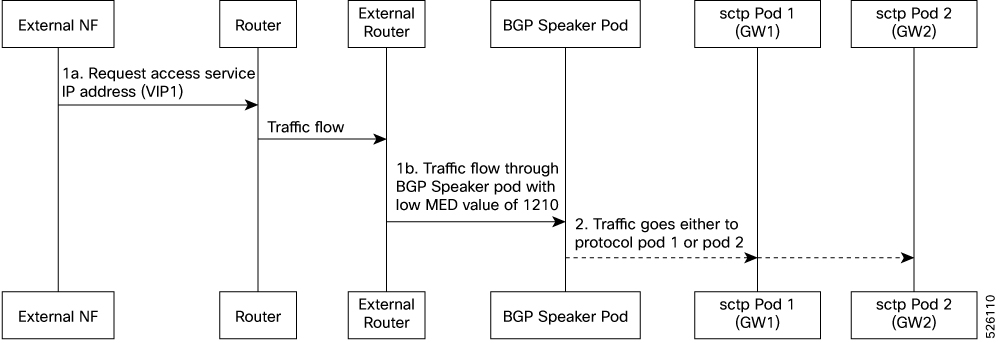
Next-Hop for Ingress Traffic: When BGP advertises a /32 service IP address, it includes a next-hop address. This next-hop is the service interface’s IP address. External networks use this address to forward incoming traffic to the specific service IP. This process ensures efficient and dynamic traffic steering.
-
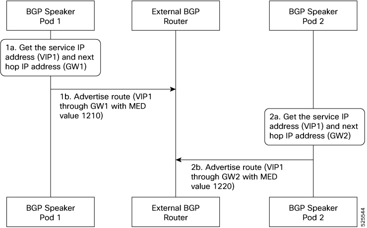
Prioritized Routing via MED: Initially, Master1 advertises the service VIP route with a lower MED value (1210) because the VIP is active on it. Master2 also advertises the route but uses a higher MED value (1220) since the VIP is not active there. External BGP peers select the route from Master1 because it has the lower MED, so incoming traffic goes to Master1. For iBGP, BGP speakers use local preference to prioritize routes.
-
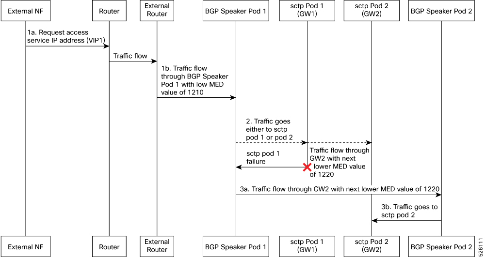
Dynamic Failover and Traffic Redirection using VIP Monitoring: If the GTP/Protocol pod on Master1 goes down, the VIP becomes unavailable on Master1 and moves to Master2. Both BGP monitors detect this change. Master1’s BGP speaker advertises the VIP route with the higher MED (1220), and Master2’s BGP speaker advertises it with the lower MED (1210). External nodes receive these updates and re-evaluate their paths. Incoming traffic then redirects seamlessly to Master2, enabling smooth failover.
-
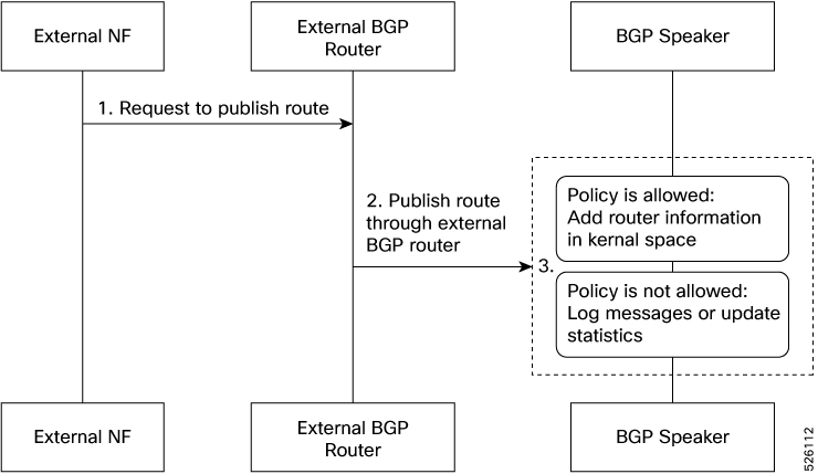
Dynamic Route Learning and Kernel Integration: BGP dynamically learns network prefixes and their next-hop IP addresses from other BGP peers. The learned routes are installed into the kernel routing table. This makes them available for forwarding outgoing traffic
-
Policy-Driven Route Filtering for Control: BGP peers may advertise many routes, but not all are accepted or installed in the local kernel routing table. BGP implementation uses routing policies to filter incoming BGP advertisements. This selective acceptance allows BGP speaker to control which IP prefixes the network learns and uses.
-
Automatic Route Re-installation on Interface Recovery: If a network interface goes down, the system removes all dependent routes from the kernel routing table. BGP speaker continuously monitors network interfaces. When a previously down interface returns to service, the BGP speaker automatically reinstalls the relevant routes, restoring network connectivity.
-
Policy-Driven Static Route Configuration: BGP speaker uses specific policies to configure static routes manually. These static routes provide fixed, predefined paths to destinations.
-
High Availability through Bonded Interfaces and Service IP: The BGP speaker’s service IP is assigned to bonded interfaces for redundancy. Each bond includes multiple physical interfaces in an active/standby setup. Each physical interface connects to a BGP router, ensuring highly available network paths for the BGP speaker.
-
BGP Peering-Triggered Bond Failover: If BGP peering sessions on the active interface go down, the BGP speaker initiates a bond switchover. This promotes a standby interface to active status. Traffic then redirects seamlessly, maintaining continuous BGP communication.
-
Debugging and Troubleshooting through KPI & Log Messages: BGP speakers provide comprehensive statistics and Key Performance Indicators (KPIs) for monitoring. They also generate detailed log messages, which are crucial for debugging and troubleshooting BGP issues.
-
BGP MED-Driven Geo-Active/Standby Deployments: In a multi-HA setup (for example, GEO Rack 1 is active and GEO Rack 2 is standby), BGP speakers on active Rack 1 advertise service IPs with lower MED values (1210 and 1220). Speakers on standby Rack 2 use higher MED values (2210 and 2220). BGP’s preference for lower MED values directs all traffic to the active rack.
-
Monitoring GEO Roles: BGP continuously monitors the active and standby roles of GEO racks. When a role changes, BGP dynamically re-advertises service IP routes with updated MED values. This ensures traffic always goes to the currently active BGP speaker.
-
BGP Speaker Status Management: BGP speaker pods report their status to a central Geo pod via ETCD. The status depends on the health of their BGP peerings. If a BGP speaker pod loses all peerings, it is marked as “down” and isolated. Traffic then shifts automatically to the other High Availability (HA) BGP speaker pod. If both HA BGP speaker pods in a GEO rack lose all peerings, the entire rack is marked as “down” in ETCD and set to “standby” by the Geo pod.
-
BGP Speaker Pod Architecture with BFD for Accelerated Failover: Each BGP speaker pod contains two containers: a BGP speaker container for routing protocol operations, and a Bidirectional Forwarding Detection (BFD) container. The BFD container quickly detects link or peer failures. This rapid detection allows BGP to respond almost instantly to connectivity issues, reducing failover times and improving network resilience.
Incoming Traffic
BGP uses TCP as the transport protocol, on port 179. Two BGP routers form a TCP connection between one another. These routers are peer routers. The peer routers exchange messages to open and confirm the connection parameters.
The BGP speaker publishes routing information of the protocol pod for incoming traffic in the active standby mode. Use the following image as an example to understand the dynamic routing functionality. There are two protocol pods, pod1 and pod2. Pod1 is active and pod2 is in the standby mode. The service IP address vip1 is configured on both the nodes, on host IP1 and host IP2. BGP pod1 is running on host IP1 and BGP pod2 on host IP2. The host IP address exposes the pod services. BGP speaker publishes the route vip1 through host IP1 and host IP2. It also publishes the preference values, 110 and 100 to determine the priority of pods.
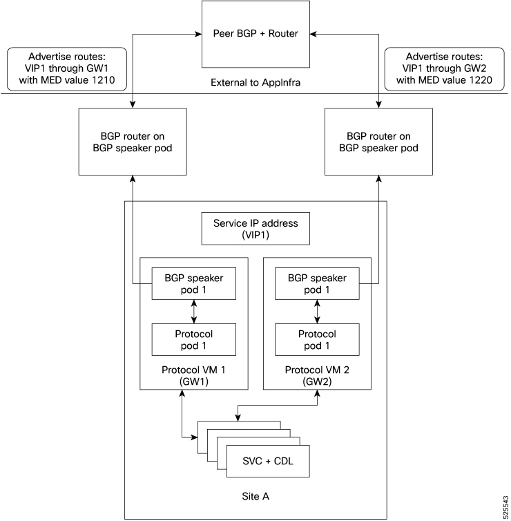
For high availability, each cluster has two BGP speaker pods with Active-standby topology. Kernel route modification is done at host network level where the protocol pod runs.
MED Value
The Local Preference is used only for IGP neighbours, whereas the MED Attribute is used only for EGP neighbours. A lower MED value is the preferred choice for BGP.
|
Bonding Interface Active |
VIP Present |
MED Value |
Local Preference |
|---|---|---|---|
|
Yes |
Yes |
1210 |
2220 |
|
Yes |
No |
1220 |
2210 |
|
No |
Yes |
1215 |
2215 |
|
No |
No |
1225 |
2205 |
Bootstrap of BGP Speaker Pods
The following sequence of steps set up the BGP speaker pods:
-
The BGP speaker pods use TCP as the transport protocol, on port 179. These pods use the AS number configured in the Ops Center CLI.
-
Register the Topology manager.
-
Select the Leader pod. The Active speaker pod is the default choice.
-
Establish connection to all the BGP peers provided by the Ops Center CLI.
-
Publish all existing routes from ETCD.
-
Configure import policies for routing by using CLI configuration.
-
Start gRPC stream server on both the speaker pods.
-
Similar to the cache pod, two BGP speaker pods must run on each Namespace.
For more information on Dynamic Routing, see the Dynamic Routing by Using BGP chapter in the UCC Serving Gateway Control Plane Function - Configuration and Administration Guide.

 Feedback