AMF-Set Deployment in Different Cluster

Table 1. Feature History

Feature Name

Release Information

Description

AMF Set Deployment in Different Cluster

2025.04.0

AMF Sets improve network reliability and session continuity by allowing multiple AMF instances to share user context and provide seamless service, even during failures. Multiple AMFs in an AMF Set share UE context using Cisco's Common Data Layer (CDL) for synchronization. When multiple AMF instances within an AMF Set are deployed across different Kubernetes clusters, if one AMF instance fails, another instance automatically continues the session using AMF load-balancing functionality. The system supports context sharing and subscriber migration across AMFs, with secure data stored and synchronized in the CDL.

Command introduced:

amf-services amf_services_name { guamis { mcc mcc_value | mnc mnc_value | region-id region_id | set-id set_id | pointer pointer_value { amf-name amf_name | backup-amf-name backup_amf_name | offline-mode } } } — Used to configure the amf-name and backup-amf-name for specific GUAMIs under AMF services.

Default Setting: Disabled – Configuration Required

Note

 
This feature is not fully qualified in this release, and is available only for testing purposes. For more information, contact your Cisco account representative.

AMF Sets in Different Cluster

AMF Sets provide a mechanism where multiple AMFs share a UE context in the network. Any one of these AMFs can provide service to the UE at a time. AMF instances can deploy across different Kubernetes clusters. If one AMF instance fails, another AMF provides support. This ensures session continuity through AMF load rebalancing.

An AMF Region consists of one or more AMF Sets. An AMF Set contains AMFs that serve a specific area and network slices. An AMF Set is unique within an AMF Region. AMF instances in the same AMF Set can be geographically distributed. They access the same context data.

An AMF Pointer identifies one or more AMFs within an AMF Set. The AMF Region Identifier (ID) identifies the region. The AMF Set ID uniquely identifies the AMF Set within the AMF Region. An AMF Name identifies an AMF. This name is a globally unique Fully Qualified Domain Name (FQDN). An AMF can be configured with one or more Globally Unique AMF Identifiers (GUAMIs) although currently AMF supports a single GUAMI. A GUAMI with a distinct AMF Pointer value associates with one AMF name at a given time.

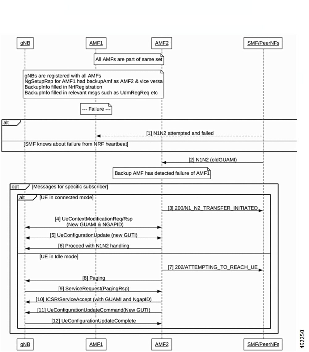
To share UE context across multiple AMF Pointers, the system introduces a CDL synchronization mechanism. This helps in AMF instance failure scenarios. The Radio Access Network (RAN) can migrate active and idle subscribers to a backup AMF i.e different pointer within same AMF set. This continues session connectivity.

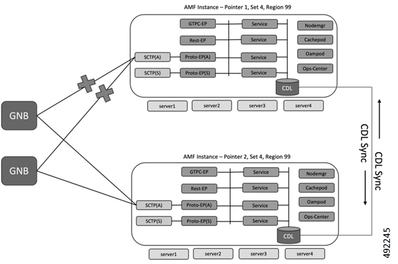
The diagram illustrates two identical deployments, each connected to a GNB. Each deployment consists of four servers (server1-server4) hosting various functional modules including GTPC-EP, Rest-EP, SCTP (Active and Standby), Proto-EP (Active and Standby), multiple services, Nodemgr, Cachepod, Oampod, and Ops-Center. A CDL is associated with each deployment, and the two CDLs are also interconnected.

Figure 1. AMF Set Deployment - Different Cluster

Key points for this feature deployment:

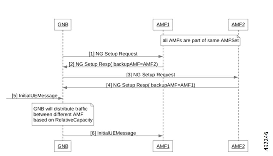
  • AMF supports sending backup AMF information in:

    • NG Setup Response message towards RAN

    • NRF registration

    • UE level messages such as in SmContextCreateData

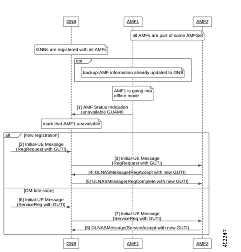
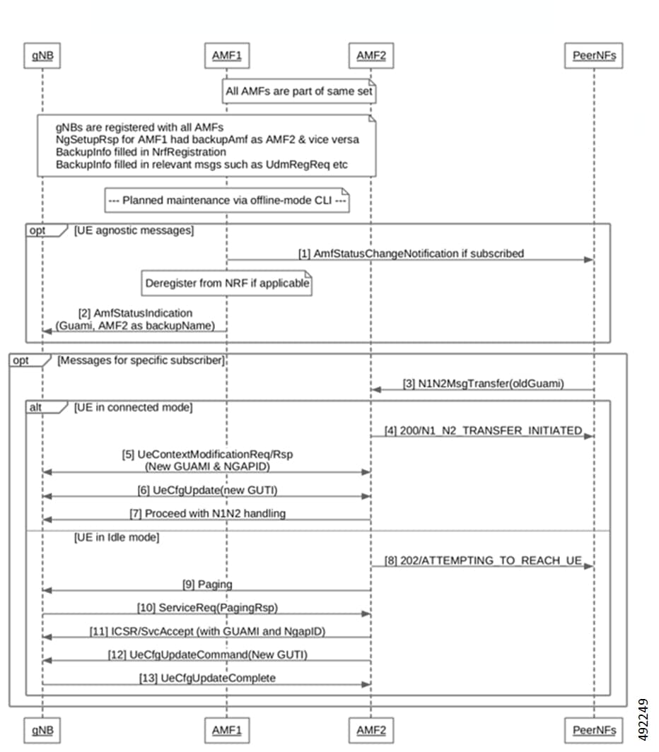
  • AMF allows peer NFs to subscribe/un-subscribe to receive status change notification when AMF goes offline for planned maintenance.

  • AMF supports sending StatusIndication to gNB when AMF goes offline for planned maintenance.

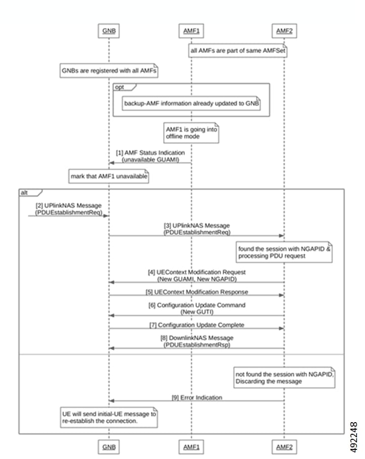
  • AMF supports sending UE Configuration Update, UE Context Modification message when a subscriber attaches to backup AMF.

Benefits of Using AMF Set Functionality

This section lists the positive outcomes that users can experience from using this feature.
  • Enhanced Resiliency: The system provides 1:1 resiliency for AMF instances.

  • Session Continuity: Subscribers maintain session connectivity during AMF instance failures or planned removals.

  • Flexible Deployment: Operators can deploy their network with multiple AMF Pointers across different Kubernetes clusters.

  • Centralized Context Sharing: The CDL synchronization mechanism ensures UE and security context sharing across AMF instances. This improves failover capabilities.

Guidelines when Using AMF Set Feature

Follow these guidelines when using AMF set feature:

  • AMF Restart: When an AMF enters offline mode, restart the AMF after maintenance activity. This cleans up and frees Globally Unique Temporary Identifiers (GUTIs) and Next Generation Application Protocol (NGAP) IDs.

  • Configuration Changes: Do not commit other configuration changes alongside offline mode changes. First, bring down the GUAMI. Then, commit any configuration change. Finally, bring the GUAMI back online.

  • Runtime Changes: You can change only backup AMF information at runtime. Do not change the AMF name and GUAMI at runtime.

  • Timer Notifications: To enable timer expiry notifications on the backup site, configure specific Command Line Interface (CLI) commands. Only timers stored in CDL are replicated (Example- TMR timer, IDT timer, Purge timer). The timer value must be more than 180 seconds for this functionality to work. Apply these commands on the backup site only after you configure the offline CLI on the primary site or when the primary site failure is detected. Both AMFs in the set should be running with identical configurations and enabled features, except for differences in IP addresses and GUAMI values.

Restrictions while using AMF Set Feature

Be aware of these restrictions when using AMF set feature:

  • Resiliency Limit: This feature supports only 1:1 resiliency. It does not support 1:N resiliency.

  • Backup AMF Notifications: A backup AMF does not send notifications if the original AMF goes down. This includes Status Indication to the gNB and Status Change Notifications to subscribed Network Functions (NFs) or the Network Repository Function (NRF).

NG Setup Request and Response

AMF instances are deployed in AMF Sets, which may contain multiple pointers. The gNB is configured to connect to all AMFs within its designated region that are part of these AMF Sets. During the NGAP Setup procedure, each AMF signals to the gNB the list of Globally Unique AMF Identifiers (GUAMI) it supports, along with its relative capacity. This relative capacity value is then utilized by the gNB for intelligent AMF selection, ensuring efficient distribution of user traffic across the available AMFs.

Figure 2. NG Setup Request/Response Call Flow

Summary

Table 2. NG Setup Request/Response Call Flow Description

Steps

Description

1

Both AMF1 and AMF2 are established as part of the same AMF Set.

The GNB initiates an NG Setup Request to AMF1.

2

AMF1 responds with an NG Setup Response, indicating AMF2 as its backup AMF.

3

gNB sends an NG Setup Request to AMF2.

4

AMF2 replies with an NG Setup Response, specifying AMF1 as its backup AMF.

5

The gNB is configured to distribute traffic between the available AMFs (AMF1 and AMF2) based on their relative capacity.

6

The gNB sends an Initial UE Message to AMF1 for a user equipment.

UE in ECM-Idle state

Figure 3. UE in ECM-Idle state Call Flow

Summary

Table 3. UE in ECM-Idle state Call Flow Description

Steps

Description

1

All AMFs (e.g., AMF1, AMF2) are configured as part of the same AMFSet, and GNBs are registered with all these AMFs, having backup-AMF information pre-updated.

AMF1 signals its transition to an offline mode by sending an AMF Status Indication (unavailable GUAMI) to the gNB.

Upon receiving the status indication, the gNB updates its internal state, marking AMF1 as unavailable

2/6

A UE, potentially in ECM-Idle state, sends an Initial-UE Message (either a Registration Request or a Service Request) containing its GUTI to the GNB.

3/7

The gNB identifies that the GUAMI in the UE's GUTI points to the now-unavailable AMF1. Following its AMF selection algorithm, the gNB selects an alternative available AMF from the AMFSet (e.g., AMF2).

The gNB forwards the Initial-UE Message (Registration Request or Service Request) to the newly selected AMF (AMF2).

4/8

AMF2 processes the received request, handling the registration or service request.

AMF2 sends a corresponding DLNASMessage (e.g., RegAccept or ServiceAccept), with a new GUTI, back to the gNB, which then facilitates the completion of the communication with the UE.

UE in ECM-connected state

Figure 4. UE in ECM-connected state Call Flow

Summary

Table 4. UE in ECM-connected state Call Flow Description

Steps

Description

1

gNBs are registered with all AMFs (AMF1, AMF2) within the same AMFSet, and backup-AMF information is updated to the gNB.

AMF1 signals to the gNB that it is going into offline mode by sending an AMF Status Indication with an unavailable GUAMI.

The gNB marks AMF1 as unavailable based on the status indication.

2

A UE in an ECM-connected state sends an UplinkNAS Message (PDUEstablishmentReq) to the gNB.

3

gNB then forwards it to AMF2 (since AMF1 is unavailable).

4

AMF2 successfully finds the session using NGAPID, processes the PDU request, and sends a UEContext Modification Request (with New GUAMI, New NGAPID) to the gNB.

5

gNB responds with a UEContext Modification Response.

6

AMF2 issues a UE Configuration Update Command (with New GUTI) to the gNB.

7

gNB acknowledges by sending a UE Configuration Update Complete.

8

AMF2 sends a DownlinkNAS Message (PDUEstablishmentRsp) to the gNB, completing the PDU session establishment.

9

If AMF2 cannot find the session with NGAPID, it discards the message and sends an Error Indication to the gNB, prompting the UE to send an initial-UE message to re-establish the connection.

Planned Maintenance and Incoming REST Message

Figure 5. Planned Maintenance and Incoming REST Message Call Flow

Summary

Table 5. Planned Maintenance and Incoming REST Message Call Flow Description

Steps

Description

1

AMF1 and AMF2 are configured as a set with mutual backup, and gNBs are registered with all AMFs, including backup information in NRF.

Planned maintenance on AMF1 is initiated via an offline-mode CLI.

2

AMF1 sends AmfStatusChangeNotification to PeerNFs (if subscribed) and deregisters from NRF.

3

AMF1 informs gNBs of its status change, designating AMF2 as the backup AMF via AmfStatusIndication.

4

A PeerNF receives a message for a specific subscriber and forwards it (N1N2MsgTransfer) to AMF2.

5

AMF2 acknowledges the N1N2 message transfer to the PeerNF.

6

If the UE is in connected mode, AMF2 updates the UE context at gNB by sending UE Context Modification message (new GUAMI, new NGAPID).

7

If the UE is in connected mode, AMF2 updates the UE with new GUTI by sending UE Configuration Update Command .

8

If the UE is in idle mode, AMF2 initiates paging to the gNB. and updates the UE's configuration (GUAMI, NGAPID, GUTI).

9

Upon receiving a ServiceRequest from the gNB, AMF2 responds with ServiceAccept with ICSR including new GUAMI and NGAP ID.

10-13

AMF2 updates the UE with new GUTI by sending UE Configuration Update Command.

Failure Detection via Incoming REST Message

Figure 6. Failure Detection via Incoming REST Message Call Flow

Summary

Table 6. Failure Detection via Incoming REST Message Call Flow Description

Steps

Description

1

All gNBs are registered with AMFs within the same set. During initial setup, backup AMF information (e.g., AMF2 as backup for AMF1) is configured and registered with the Network Repository Function (NRF).

An AMF (e.g., AMF1) fails. This failure is detected by the SMF or any other peer NF, either by NRF heartbeat or failure received when the message was sent to AMF1.

2

Once SMF is aware of the failure, SMF sends the same message to AMF2 (backup AMF).

3-5

AMF2 responds to the above request

For UEs in connected mode. AMF2 sends UeContextModificationReq/Rsp (with new GUAMI and NGAPID) and UeConfigurationUpdate (with a new GUTI).

8-10

For UEs in idle mode, AMF2 triggers paging. gNB responds with ServiceReq(PagingRsp). AMF2 sends ICSR/ServiceAccept (with GUAMI and NgapID).

11

AMF2 sends a UeConfigurationUpdateCommand with a new GUTI to the gNB.

12

The gNB completes the UE configuration update process, ensuring the UE is now managed by the new AMF.

Configure AMF Name and Backup AMF Name

Use this procedure to configure the AMF name and backup AMF name for specific GUAMIs within an AMF service.

Before you begin

Review the Guidelines and Limitations sections in this document.

  • The amf-name CLI directly under amf-services is deprecated. The amf-name must now be configured mandatorily under the guamis configuration.

  • The backup-amf-name specifies the AMF that acts as a backup for the given GUAMI when the current AMF goes down, as used in NgSetupRsp.

Procedure


Step 1

Enter the AMF service configuration mode.

amf-services amf_services_name

Example:

[amf] amf(config)# amf-services am1 

Step 2

Configure the GUAMI parameters, including Mobile Country Code (MCC), Mobile Network Code (MNC), Region ID, Set ID, and Pointer.

guamis mcc mcc_value mnc mnc_value region-id region_id set-id set_id pointer pointer_value

Example:

[amf] amf(config-amf-services-am1)# guamis mcc 123 mnc 456 region-id 1 set-id 14 pointer 3 

Step 3

Specify the AMF name for the configured GUAMI.

amf-name amf_name

Example:

[amf] amf(config-amf-services-am1-guamis)# amf-name amf1 

Step 4

Specify the backup AMF name for the configured GUAMI.

backup-amf-name backup_amf_name

Example:

[amf] amf(config-amf-services-am1-guamis)# backup-amf-name amf2 

backup-amf-name acts as backup for given GUAMI when current AMF goes down.

Step 5

Enable offline mode for the GUAMI.

offline-mode

Example:

[amf] amf(config-amf-services-am1-guamis)# offline-mode 

Use this command only in AMF maintenance mode.

Step 6

Configure the list of GUAMIs where current AMF will act as backup.

backup-guami-served-by-amf [guamis]

Step 7

Save and commit the configuration.

Example:

[amf] amf(config-amf-services-am1)# end 

This command allows you to either commit or ignore the configurations. Entering yes allows you to save or modify the configurations.


CDL Replication Configuration

CDL currently supports replication across different cluster. Here AMF instance 1 and AMF instance2 are deployed with inline CDL.

  • CDL instance replicates data to the peer site as soon as the transaction completes and AMF application store that information into CDL.

  • CDL notifies the timer expiry to only that AMF instance which has last updated the CDL data.

Following are the CDL configuration requirements.

  • cdl-system-id should be 1 on site-1, 2 on site-2. Make sure cdl-system-ids are not same on both sites.

  • Node-type configuration is not required when label-config is configured.

See https://www.cisco.com/c/en/us/td/docs/wireless/ucc/smi/cdl-config-guide/ucc_5g_cdl_config_and_admin_guide/m_cdl_config_guide.html#reference_f5w_1xj_y3b for all CDL related configuration for this feature.