Mesh Network Components
This chapter describes the mesh network components.
The Cisco wireless mesh network has four core components:
-
Cisco Aironet series access points

Note
Cisco Aironet 1520 series mesh access points are not supported because of their End-of-Life status.
-
Cisco Wireless LAN Controller (hereafter referred to as controller)
This chapter contains the following sections:
Mesh Access Points
- Licensing for Mesh Access Points on a 5508, 3504 5520 and 8540 Series Cisco Comptroller
- Access Point Roles
- Network Access
- Network Segmentation
- Cisco Indoor Mesh Access Points
- Cisco Outdoor Mesh Access Points
Licensing for Mesh Access Points on a 5508, 3504 5520 and 8540 Series Cisco Comptroller
To use both mesh and non-mesh access points with a Cisco 3504, 5500 and 8500 Series Controller, only the base license is required from the 7.0 release and later releases. For more information about obtaining and installing licenses, see the Cisco Wireless LAN Controller Configuration Guide at http://www.cisco.com/en/US/products/ps10315/products_installation_and_configuration_guides_list.html.
Access Point Roles
Access points within a mesh network operate in one of the following two ways:
In rel 8.6 Mesh Leaf Node Mode added
Support is added to configure IOS based mesh APs with lower performance to work only as a leaf node or basically be the last one in the tree, to prevent the wireless backhaul performance from being downgraded.
While the RAPs have wired connections to their controller, the MAPs have wireless connections to their controller.
MAPs communicate among themselves and back to the RAP using wireless connections over the 802.11a/n radio backhaul. MAPs use the Cisco Adaptive Wireless Path Protocol (AWPP) to determine the best path through the other mesh access points to the controller.
Bridge mode access points support CleanAir in mesh backhaul at 5GHz frequency and provides only the interference device report (IDR) and Air Quality Index (AQI)reports.
Note | The RAP or MAP does not generate Bridge Protocol Data Unit (BPDU) itself. However, the RAP or MAP forwards the BPDU to upstream devices if the RAP or MAP received the BPDU from its connected wired or wireless interface across the network. |
Network Access
Wireless mesh networks can simultaneously carry two different traffic types. They are as follows:
Wireless LAN client traffic terminates on the controller, and the Ethernet traffic terminates on the Ethernet ports of the mesh access points.
Access to the wireless LAN mesh for mesh access points is managed by the following authentication methods:
-
MAC authentication—Mesh access points are added to a database that can be referenced to ensure they are provided access to a given controller and mesh network.
-
External RADIUS Authentication—Mesh access points can be externally authorized using a RADIUS server such as Cisco ACS (4.1 and later) and ISE that supports the client authentication type of Extensible Authentication Protocol-FAST (EAP-FAST) with certificates and and WPA2/PSK on the WLCs.
Network Segmentation
Membership to the wireless LAN mesh network for mesh access points is controlled by the bridge group names (BGNs). Mesh access points can be placed in similar bridge groups to manage membership or provide network segmentation.
Cisco Indoor Mesh Access Points
-
Cisco Aironet 1600 Series Access Points
-
Cisco Aironet 1700 Series Access Points
-
Cisco Aironet 2600 Series Access Points
-
Cisco Aironet 2700 Series Access Points
-
Cisco Aironet 3500 Series Access Points
-
Cisco Aironet 3600 Series Access Points
-
Cisco Aironet 3700 Series Access Points
-
Cisco Aironet 1530 Series Access Points
-
Cisco Aironet 1540 Series Access Points
-
Cisco Aironet 1550 Series Access Points
-
Cisco Aironet 1560 Series Access Points
-
Cisco Aironet 1570 Series Access Points
-
Cisco Industrial Wireless 3700 Series Access Points
Note
In 8.5 release the following AP s will be supported.
Note | For more information about controller software support for access points, see the Cisco Wireless Solutions Software Compatibility Matrix at http://www.cisco.com/en/US/docs/wireless/controller/5500/tech_notes/Wireless_Software_Compatibility_Matrix.html. |
Enterprise 11n/ac mesh is an enhancement added to the CUWN feature to work with the 802.11n/ac access points. Enterprise 11ac mesh features are compatible with non-802.11ac mesh but adds higher backhaul and client access speeds. The 802.11ac indoor access points are two-radio Wi-Fi infrastructure devices for select indoor deployments. One radio can be used for local (client) access for the access point and the other radio can be configured for wireless backhaul. If Universal Backhaul Access is enabled, the 5-GHz and 2.4–GHz radios in rel 8.2 can be used for local (client) access as well as a backhaul. Enterprise 11ac mesh supports P2P, P2MP, and mesh types of architectures.
You have a choice of ordering indoor access points directly into the bridge mode, so that these access points can be used directly as mesh access points. If you have these access points in a local mode (non-mesh), then you have to connect these access points to the controller and change the AP mode to the bridge mode (mesh). This scenario can become cumbersome particularly if the volume of the access points being deployed is large and if the access points are already deployed in the local mode for a traditional non-mesh wireless coverage.
The Cisco indoor mesh access points are equipped with the following two simultaneously operating radios:
-
From rel 8.2 2.4 GHz radio used for data backhaul and client access if UBA is enable
-
5-GHz radio used for data backhaul and client access if Universal Backhaul Access is enabled
The 5-GHz radio supports the 5.15 GHz, 5.25 GHz, 5.47 GHz, and 5.8 GHz bands.
Cisco Outdoor Mesh Access Points
Cisco outdoor mesh access points comprise of the Cisco Aironet 1500 series access points. The 1500 series includes 1572 11ac outdoor access points, 1552 and 1532 11n outdoor mesh access points, and the newer 1540 and 1560 11ac wave 2 series..
Cisco 1500 series mesh access points are the core components of the wireless mesh deployment. AP1500s are configured by both the controller (GUI and CLI) and Cisco Prime Infrastructure. Communication between outdoor mesh access points (MAPs and RAPs) is over the 802.11a/n/ac radio backhaul. Client traffic is generally transmitted over the 802.11b/g/n radio (802.11a/n/ac can also be configured to accept client traffic).
The mesh access point can also operate as a relay node for other access points not directly connected to a wired network. Intelligent wireless routing is provided by the Adaptive Wireless Path Protocol (AWPP). This Cisco protocol enables each mesh access point to identify its neighbors and intelligently choose the optimal path to the wired network by calculating the cost of each path in terms9 of the signal strength and the number of hops required to get to a controller.
Uplinks support includes Gigabit Ethernet (1000BASE-T) and a small form-factor (SFP) slot that can be plugged for a fiber or cable modem interface. Both single mode and multimode SFPs up to 1000BASE-BX are supported. The cable modem can be DOCSIS 2.0 or DOCSIS/EuroDOCSIS 3.0 depending upon the type of mesh access point.
AP1550s are available in a hazardous location hardware enclosure. When configured, the AP1500 complies with safety standards for Class I, Division 2, Zone 2 hazardous locations.
-
Local mode—In this mode, the AP can handle clients on its assigned channel or while monitoring all channels on the band over a 180-second period. During this time, the AP listens on each channel for 50 milliseconds for rogue client beacons, noise floor measurements, interference, and IDS events. The AP also scans for CleanAir interference on the channel.
-
FlexConnect mode—FlexConnect is a wireless solution for branch office and remote office deployments. The FlexConnect mode enables you to configure and control access points in a branch or remote office from the corporate office through a WAN link without having to deploy a controller in each office. The FlexConnect mode can switch client data traffic locally and perform client authentication locally when the connection to the controller is lost. When connected to the controller, the FlexConnect mode can also tunnel traffic back to the controller.
-
Flex+Bridge Mode—In this mode, both the Flexconnect and Bridge mode configuration options are available on the access point.
-
Monitor mode—In this mode, the AP radios are in the receive state. The AP scans all the channels every 12 seconds for rogue client beacons, noise floor measurements, interference, IDS events, and CleanAir intruders.
-
Rogue Detector mode—In this mode, the AP radio is turned off, and the AP listens only to the wired traffic. The controller passes the APs that are configured as rogue detectors as well as lists of suspected rogue clients and AP MAC addresses. The rogue detector listens for ARP packets and can be connected to all broadcast domains through a trunk link.
-
Sniffer mode—In this mode, the AP captures and forwards all packets on a channel to a remote device that decodes the packets with packet analyzer software such as Wireshark.
-
Bridge mode—In this mode, the AP is configured to build a wireless mesh network where wired network cabling is not available.
Note | You can configure these modes using both the GUI and CLI. For configuration instructions, see the Cisco Wireless LAN Controller Configuration Guide. |
Note | MAPs can only be configured in Bridge / Flex+Bridge mode regardless of their wired or wireless backhaul. If the MAPs have a wired backhaul, you must change their AP role to RAP before you change the AP Mode. |
Note | For complete details and specification of all models of outdoor Mesh AP please visit this link below: |
- Frequency Bands
- Dynamic Frequency Selection
- Antennas
- Client Access Certified Antennas (Third-Party Antennas)
Frequency Bands
Both the 2.4-GHz and 5-GHz frequency bands are supported on the indoor and outdoor access points.
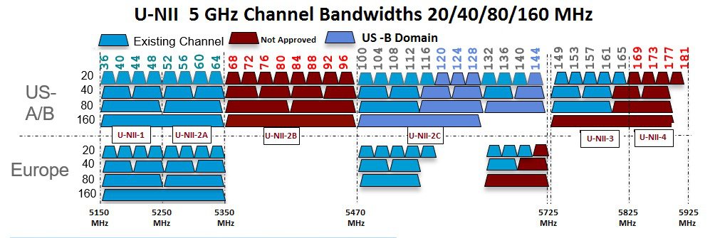
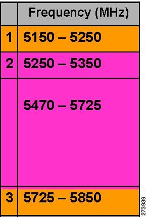
FCC United States
U-NII-1
This band can now be used indoors and outdoors
Maximum power is increased to 30 dBm (1 Watt) assuming antenna is 6 dBi
Power should be reduced by 1 dB for every dB antenna gain exceeds 6 dBi
When used outdoors, EIRP power in the upwards direction above 30 degrees is limited to 125 mW (20.9 dBm)
U-NII-2A and U-NII2C
Must include Dynamic Frequency Selection (DFS) radar detection
Terminal Doppler Weather Radar (TWDR) bands (channels 120, 124 & 128) are now available with new DFS test requirements
U-NII-3
Band extended from 5825 MHz to 5850 MHz
Europe
U-NII-1
23 dBm Maximum–Not permitted for outdoor usage
U-NII-2A
23 dBm Maximum–Not permitted for outdoor usage
U-NII-2C
30 dBm Maximum
U-NII-3
Only available in UK at 23 dBm for Indoor usage only
Dynamic Frequency Selection
Previously, devices employing radar operated in frequency subbands without other competing services. However, controlling regulatory bodies are attempting to open and share these bands with new services like wireless mesh LANs (IEEE 802.11).
To protect existing radar services, the regulatory bodies require that devices wishing to share the newly opened frequency subband behave in accordance with the Dynamic Frequency Selection (DFS) protocol. DFS dictates that to be compliant, a radio device must be capable of detecting the presence of radar signals. When a radio detects a radar signal, it is required to stop transmitting to for at least 30 minutes to protect that service. The radio then selects a different channel to transmit on but only after monitoring it. If no radar is detected on the projected channel for at least one minute, then the new radio service device may begin transmissions on that channel.
The AP performs a DFS scan on the new DFS channel for 60 seconds. However, if a neighboring AP is already using that new DFS channel, the AP does not perform the DFS scan.
The process for a radio to detect and identify a radar signal is a complicated task that sometimes leads to incorrect detects. Incorrect radar detections can occur due to a large number of factors, including due to uncertainties of the RF environment and the ability of the access point to reliably detect actual on-channel radar.
The 802.11h standard addresses DFS and Transmit Power Control (TPC) as it relates to the 5-GHz band. Use DFS to avoid interference with radar and TPC to avoid interference with satellite feeder links.
Antennas
Overview
Antenna choice is a vital component of any wireless network deployment. There are two broad types of antennas:
Each type of antenna has a specific use and is most beneficial in specific types of deployments. Because antennas distribute RF signal in large lobed coverage areas determined by antenna design, successful coverage is heavily reliant on antenna choice.
An antenna gives a mesh access point three fundamental properties: gain, directivity, and polarization:
-
Gain—A measure of the increase in power. Gain is the amount of increase in energy that an antenna adds to an RF signal.
-
Directivity—The shape of the transmission pattern. If the gain of the antenna increases, the coverage area decreases. The coverage area or radiation pattern is measured in degrees. These angles are measured in degrees and are called beam-widths.
-
Polarization—The orientation of the electric field of the electromagnetic wave through space. Antennas can be polarized either horizontally or vertically, though other kinds of polarization are available. Both antennas in a link must have the same polarization to avoid an additional unwanted loss of signal. To improve the performance, an antenna can sometimes be rotated to alter polarization, which reduces interference. A vertical polarization is preferable for sending RF waves down concrete canyons, and horizontal polarization is generally more preferable for wide area distribution. Polarization can also be harnessed to optimize for RF bleed-over when reducing RF energy to adjacent structures is important. Most omnidirectional antennas ship with vertical polarization as their default.
Antenna Options
A wide variety of antennas are available to provide flexibility when you deploy the mesh access points over various terrains.Refer to the applicable accesspoint data sheet or ordering guide for a list of supported antennas.
See the Cisco Aironet Antenna and Accessories Reference Guide on Cisco antennas and accessories at http://www.cisco.com/en/US/prod/collateral/wireless/ps7183/ps469/product_data_sheet09186a008008883b.html
The deployment and design, limitations and capabilities, and basic theories of antennas as well as installation scenarios, regulatory information, and technical specifications are addressed in detail.http://wwwin.cisco.com/c/cec/prods-industry/selling-en/products/wireless/ap/aironet-acc.html
Client Access Certified Antennas (Third-Party Antennas)
You can use third-party antennas with AP1500s. However, note the following:
-
Cisco does not track or maintain information about the quality, performance, or reliability of the noncertified antennas and cables.
-
RF connectivity and compliance is the customer’s responsibility.
-
Compliance is only guaranteed with Cisco antennas or antennas that are of the same design and gain as Cisco antennas.
-
Cisco Technical Assistance Center (TAC) has no training or customer history with regard to non Cisco antennas and cables.
Cisco Wireless LAN Controllers
The wireless mesh solution is supported on Cisco 2500, 3500, 5508, 5520, WiSM–2 and 8500 Series Wireless LAN Controllers.
For more information about the Cisco 2500, 3500, 5500, and 8500 Series Wireless LAN Controllers, see http://www.cisco.com/en/US/products/ps6302/Products_Sub_Category_Home.html.
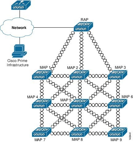
Cisco Prime Infrastructure
The Cisco Prime Infrastructure provides a graphical platform for wireless mesh planning, configuration, and management. Network managers can use the Prime Infrastructure to design, control, and monitor wireless mesh networks from a central location.
With the Prime Infrastructure, network administrators have a solution for RF prediction, policy provisioning, network optimization, troubleshooting, user tracking, security monitoring, and wireless LAN systems management. Graphical interfaces make wireless LAN deployment and operations simple and cost-effective. Detailed trending and analysis reports make the Prime Infrastructure vital to ongoing network operations.
The Prime Infrastructure runs on a server platform with an embedded database, which provides scalability that allows hundreds of controllers and thousands of Cisco mesh access points to be managed. Controllers can be located on the same LAN as the Prime Infrastructure, on separate routed subnets, or across a wide-area connection.
Architecture
Control and Provisioning of Wireless Access Points
Control and provisioning of wireless access points (CAPWAP) is the provisioning and control protocol used by the controller to manage access points (mesh and nonmesh) in the network.
CAPWAP Discovery on a Mesh Network
The process for CAPWAP discovery on a mesh network is as follows:
-
A mesh access point establishes a link before starting CAPWAP discovery, whereas a non mesh access point starts CAPWAP discovery using a static IP for the mesh access point, if any.
-
The mesh access point initiates CAPWAP discovery using a static IP for the mesh access point on the Layer 3 network or searches the network for its assigned primary, secondary, or tertiary controller. A maximum of 10 attempts are made to connect.
Note
The mesh access point searches a list of controllers configured on the access point (primed) during setup.
-
If Step 2 fails after 10 attempts, the mesh access point falls back to DHCP and attempts to connect in 10 tries.
-
If both Steps 2 and 3 fail and there is no successful CAPWAP connection to a controller.
-
If there is no discovery after attempting Steps 2, 3, and 4, the mesh access point tries the next link.
Dynamic MTU Detection
If the MTU is changed in the network, the access point detects the new MTU value and forwards that to the controller to adjust to the new MTU. After both the access point and the controller are set at the new MTU, all data within their path are fragmented into the new MTU. The new MTU size is used until it is changed. The default MTU on switches and routers is 1500 bytes.
Adaptive Wireless Path Protocol
The Adaptive Wireless Path Protocol (AWPP) is designed specifically for wireless mesh networking to provide ease of deployment, fast convergence, and minimal resource consumption.
AWPP takes advantage of the CAPWAP WLAN, where client traffic is tunneled to the controller and is therefore hidden from the AWPP process. Also, the advance radio management features in the CAPWAP WLAN solution are available to the wireless mesh network and do not have to be built into AWPP.
AWPP enables a remote access point to dynamically find the best path back to a RAP for each MAP that is part of the RAP’s bridge group (BGN). Unlike traditional routing protocols, AWPP takes RF details into account.
To optimize the route, a MAP actively solicits neighbor MAP. During the solicitation, the MAP learns all of the available neighbors back to a RAP, determines which neighbor offers the best path, and then synchronizes with that neighbor. The path decisions of AWPP are based on the link quality and the number of hops.
AWPP automatically determines the best path back to the CAPWAP controller by calculating the cost of each path in terms of the signal strength and number of hops. After the path is established, AWPP continuously monitors conditions and changes routes to reflect changes in conditions. AWPP also performs a smoothing function to signal condition information to ensure that the ephemeral nature of RF environments does not impact network stability.
Traffic Flow
The traffic flow within the wireless mesh can be divided into three components:
-
Overlay CAPWAP traffic that flows within a standard CAPWAP access point deployment; that is, CAPWAP traffic between the CAPWAP access point and the CAPWAP controller.
As the CAPWAP model is well known and the AWPP is a proprietary protocol, only the wireless mesh data flow is described. The key to the wireless mesh data flow is the address fields of the 802.11 frames being sent between mesh access points.
An 802.11 data frame can use up to four address fields: receiver, transmitter, destination, and source. The standard frame from a WLAN client to an AP uses only three of these address fields because the transmitter address and the source address are the same. However, in a WLAN bridging network, all four address fields are used because the source of the frame might not be the transmitter of the frame, because the frame might have been generated by a device behind the transmitter.
Figure 1 shows an example of this type of framing. The source address of the frame is MAP:03:70, the destination address of this frame is the controller (the mesh network is operating in Layer 2 mode), the transmitter address is MAP:D5:60, and the receiver address is RAP:03:40.
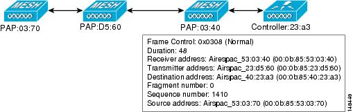
As this frame is sent, the transmitter and receiver addresses change on a hop-by-hop basis. AWPP is used to determine the receiver address at each hop. The transmitter address is known because it is the current mesh access point. The source and destination addresses are the same over the entire path.
If the RAP’s controller connection is Layer 3, the destination address for the frame is the default gateway MAC address, because the MAP has already encapsulated the CAPWAP in the IP packet to send it to the controller, and is using the standard IP behavior of using ARP to find the MAC address of the default gateway.
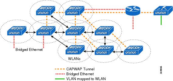
Each mesh access point within the mesh forms an CAPWAP session with a controller. WLAN traffic is encapsulated inside CAPWAP and is mapped to a VLAN interface on the controller. Bridged Ethernet traffic can be passed from each Ethernet interface on the mesh network and does not have to be mapped to an interface on the controller (see Figure 2).
Mesh Neighbors, Parents, and Children
Relationships among mesh access points are as a parent, child, or neighbor (see Figure 1).
-
A parent access point offers the best route back to the RAP based on its ease values. A parent can be either the RAP itself or another MAP.
-
A child access point selects the parent access point as its best route back to the RAP.
-
A neighbor access point is within RF range of another access point but is not selected as its parent or a child because its ease values are lower than that of the parent.
Figure 6. Parent, Child, and Neighbor Access Points 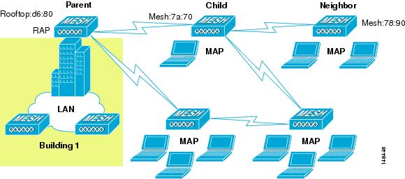
Criteria to Choose the Best Parent
AWPP follows this process in selecting parents for a RAP or MAP with a radio backhaul:
A list of channels with neighbors is generated by passive scanning in the scan state, which is a subset of all backhaul channels.
The channels with neighbors are sought by actively scanning in the seek state and the backhaul channel is changed to the channel with the best neighbor.
The parent is set to the best neighbor and the parent-child handshake is completed in the seek state.
Parent maintenance and optimization occurs in the maintain state.
This algorithm is run at startup and whenever a parent is lost and no other potential parent exists, and is usually followed by CAPWAP network and controller discovery. All neighbor protocol frames carry the channel information.
Parent maintenance occurs by the child node sending a directed NEIGHBOR_REQUEST to the parent and the parent responding with a NEIGHBOR_RESPONSE.
Parent optimization and refresh occurs by the child node sending a NEIGHBOR_REQUEST broadcast on the same channel on which its parent resides, and by evaluating all responses from neighboring nodes on the channel.
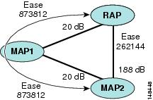
A parent mesh access point provides the best path back to a RAP. AWPP uses ease to determine the best path. Ease can be considered the opposite of cost, and the preferred path is the path with the higher ease.
Ease Calculation
Ease is calculated using the SNR and hop value of each neighbor, and applying a multiplier based on various SNR thresholds. The purpose of this multiplier is to apply a spreading function to the SNRs that reflects various link qualities.
Figure 1 shows the parent path selection where MAP2 prefers the path through MAP1 because the adjusted ease value (436906) though this path is greater then the ease value (262144) of the direct path from MAP2 to RAP.
Parent Decision
A parent mesh access point is chosen by using the adjusted ease, which is the ease of each neighbor divided by the number of hops to the RAP:
SNR Smoothing
One of the challenges in WLAN routing is the ephemeral nature of RF, which must be considered when analyzing an optimal path and deciding when a change in path is required. The SNR on a given RF link can change substantially from moment to moment, and changing route paths based on these fluctuations results in an unstable network, with severely degraded performance. To effectively capture the underlying SNR but remove moment-to-moment fluctuations, a smoothing function is applied that provides an adjusted SNR.
In evaluating potential neighbors against the current parent, the parent is given 20 percent of bonus-ease on top of the parent's calculated ease, to reduce the ping-pong effect between parents. A potential parent must be significantly better for a child to make a switch. Parent switching is transparent to CAPWAP and other higher-layer functions.
Loop Prevention
To ensure that routing loops are not created, AWPP discards any route that contains its own MAC address. That is, routing information apart from hop information contains the MAC address of each hop to the RAP; therefore, a mesh access point can easily detect and discard routes that loop.
 Feedback