Mesh Access Points
Licensing for Mesh Access Points on a 5508, 5520 and 8540 Series Cisco Comptroller
To use both mesh and non-mesh access points with a Cisco 5500 and 8500 Series Controller, only the base license is required from the 7.0 release and later releases. For more information about obtaining and installing licenses, see the Cisco Wireless LAN Controller Configuration Guide at http://www.cisco.com/en/US/products/ps10315/products_installation_and_configuration_guides_list.html.
Access Point Roles
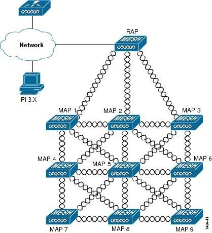
Access points within a mesh network operate in one of the following two ways:
-
Root access point (RAP)
-
Mesh access point (MAP)

Note
All access points are configured and shipped as mesh access points. To use an access point as a root access point, you must reconfigure the mesh access point to a root access point. In all mesh networks, ensure that there is at least one root access point.
While the RAPs have wired connections to their controller, the MAPs have wireless connections to their controller.
MAPs communicate among themselves and back to the RAP using wireless connections over the 802.11a/n/g radio backhaul. MAPs use the Cisco Adaptive Wireless Path Protocol (AWPP) to determine the best path through the other mesh access points to the controller.
Bridge mode access points support CleanAir in mesh backhaul and provides only the interference device report (IDR) and Air Quality Index (AQI)reports.
Note |
The RAP or MAP does not generate Bridge Protocol Data Unit (BPDU) itself. However, the RAP or MAP forwards the BPDU to upstream devices if the RAP or MAP received the BPDU from its connected wired or wireless interface across the network. |
Network Access
Wireless mesh networks can simultaneously carry two different traffic types. They are as follows:
-
Wireless LAN client traffic
-
MAP Ethernet port traffic
Wireless LAN client traffic terminates on the controller, and the Ethernet traffic terminates on the Ethernet ports of the mesh access points.
Access to the wireless LAN mesh for mesh access points is managed by the following authentication methods:
-
MAC authentication—Mesh access points are added to a database that can be referenced to ensure they are provided access to a given controller and mesh network.
-
External RADIUS Authentication—Mesh access points can be externally authorized using a RADIUS server such as Cisco ACS (4.1 and later) that supports the client authentication type of Extensible Authentication Protocol-FAST (EAP-FAST) with certificates.
Network Segmentation
Membership to the wireless LAN mesh network for mesh access points is controlled by the bridge group names (BGNs). Mesh access points can be placed in similar bridge groups to manage membership or provide network segmentation.
Cisco Indoor Mesh Access Points
-
Cisco Aironet 1600 Series Access Points
-
Cisco Aironet 1700 Series Access Points
-
Cisco Aironet 2600 Series Access Points
-
Cisco Aironet 2700 Series Access Points
-
Cisco Aironet 3500 Series Access Points
-
Cisco Aironet 3600 Series Access Points
-
Cisco Aironet 3700 Series Access Points
-
Cisco Aironet 1530 Series Access Points
-
Cisco Aironet 1550 Series Access Points
-
Cisco Aironet 1560 Series Access Points
-
Cisco Aironet 1570 Series Access Points
-
Cisco Industrial Wireless 3700 Series Access Points
Note
In 8.4 release the following AP s will be supported.
-
1700
-
2700
-
3700
-
Note |
For more information about controller software support for access points, see the Cisco Wireless Solutions Software Compatibility Matrix at http://www.cisco.com/en/US/docs/wireless/controller/5500/tech_notes/Wireless_Software_Compatibility_Matrix.html. |
Enterprise 11n/ac mesh is an enhancement added to the CUWN feature to work with the 802.11n/ac access points. Enterprise 11ac mesh features are compatible with non-802.11ac mesh but adds higher backhaul and client access speeds. The 802.11ac indoor access points are two-radio Wi-Fi infrastructure devices for select indoor deployments. One radio can be used for local (client) access for the access point and the other radio can be configured for wireless backhaul. If Universal Backhaul Access is enabled, the 5-GHz and 2.4–GHz radios in rel 8.2 can be used for local (client) access as well as a backhaul. Enterprise 11ac mesh supports P2P, P2MP, and mesh types of architectures.
The 802.11ac provides enterprise-class reliability and wired network like performance. It supports three spatial streams and 80 MHz wide channels for a maximum data rate of 1.3 Gbps. This is three times the maximum data rate of today's high-end enterprise 802.11n access point.
You have a choice of ordering indoor access points directly into the bridge mode, so that these access points can be used directly as mesh access points. If you have these access points in a local mode (non-mesh), then you have to connect these access points to the controller and change the AP mode to the bridge mode (mesh). This scenario can become cumbersome particularly if the volume of the access points being deployed is large and if the access points are already deployed in the local mode for a traditional non-mesh wireless coverage.
The Cisco indoor mesh access points are equipped with the following two simultaneously operating radios:
-
From rel 8.2 2.4 GHz radio used for data backhaul and client access if UBA is enable
-
5-GHz radio used for data backhaul and client access if Universal Backhaul Access is enabled
The 5-GHz radio supports the 5.15 GHz, 5.25 GHz, 5.47 GHz, and 5.8 GHz bands.
Cisco Outdoor Mesh Access Points
Cisco outdoor mesh access points comprise of the Cisco Aironet 1500 series access points. The 1500 series includes 1572 11ac outdoor access points, 1552 and 1532 11n outdoor mesh access points, and the 1560 11ac wave 2 series.1532 dual radio mesh access points .
Cisco 1500 series mesh access points are the core components of the wireless mesh deployment. AP1500s are configured by both the controller (GUI and CLI) and Cisco Prime Infrastructure. Communication between outdoor mesh access points (MAPs and RAPs) is over the 802.11a/n/ac radio backhaul. Client traffic is generally transmitted over the 802.11b/g/n radio (802.11a/n/ac can also be configured to accept client traffic).
The mesh access point can also operate as a relay node for other access points not directly connected to a wired network. Intelligent wireless routing is provided by the Adaptive Wireless Path Protocol (AWPP). This Cisco protocol enables each mesh access point to identify its neighbors and intelligently choose the optimal path to the wired network by calculating the cost of each path in terms9 of the signal strength and the number of hops required to get to a controller.
Uplinks support includes Gigabit Ethernet (1000BASE-T) and a small form-factor (SFP) slot that can be plugged for a fiber or cable modem interface. Both single mode and multimode SFPs up to 1000BASE-BX are supported. The cable modem can be DOCSIS 2.0 or DOCSIS/EuroDOCSIS 3.0 depending upon the type of mesh access point.
AP1550s are available in a hazardous location hardware enclosure. When configured, the AP1500 complies with safety standards for Class I, Division 2, Zone 2 hazardous locations.
-
Local mode—In this mode, the AP can handle clients on its assigned channel or while monitoring all channels on the band over a 180-second period. During this time, the AP listens on each channel for 50 milliseconds for rogue client beacons, noise floor measurements, interference, and IDS events. The AP also scans for CleanAir interference on the channel.
-
FlexConnect mode—FlexConnect is a wireless solution for branch office and remote office deployments. The FlexConnect mode enables you to configure and control access points in a branch or remote office from the corporate office through a WAN link without having to deploy a controller in each office. The FlexConnect mode can switch client data traffic locally and perform client authentication locally when the connection to the controller is lost. When connected to the controller, the FlexConnect mode can also tunnel traffic back to the controller.
-
Flex+Bridge Mode—In this mode, both the Flexconnect and Bridge mode configuration options are available on the access point.
-
Monitor mode—In this mode, the AP radios are in the receive state. The AP scans all the channels every 12 seconds for rogue client beacons, noise floor measurements, interference, IDS events, and CleanAir intruders.
-
Rogue Detector mode—In this mode, the AP radio is turned off, and the AP listens only to the wired traffic. The controller passes the APs that are configured as rogue detectors as well as lists of suspected rogue clients and AP MAC addresses. The rogue detector listens for ARP packets and can be connected to all broadcast domains through a trunk link.
-
Sniffer mode—In this mode, the AP captures and forwards all packets on a channel to a remote device that decodes the packets with packet analyzer software such as Wireshark.
-
Bridge mode—In this mode, the AP is configured to build a wireless mesh network where wired network cabling is not available.
-
Flex+Bridge Mode—In this mode, both the Flexconnect and Bridge mode configuration options are available on the access point.
Note |
You can configure these modes using both the GUI and CLI. For configuration instructions, see the Cisco Wireless LAN Controller Configuration Guide. |
Note |
MAPs can only be configured in Bridge / Flex+Bridge mode regardless of their wired or wireless backhaul. If the MAPs have a wired backhaul, you must change their AP role to RAP before you change the AP Mode. |
Battery Backup Module (Optional)
Note |
For a complete listing of optional hardware components for AP1520s such as mounting brackets, power injectors, and power tap adapters, see http://www.cisco.com/en/US/prod/collateral/wireless/ps5679/ps8368/product_data_sheet0900aecd8066a157.html |
Frequency Bands
Both the 2.4-GHz and 5-GHz frequency bands are supported on the indoor and outdoor access points.
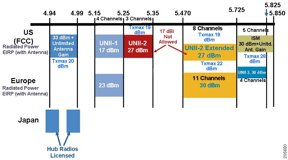
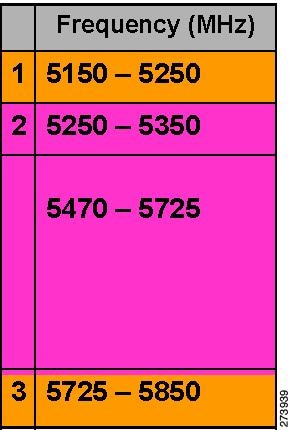
The 5-GHz band is a conglomerate of three bands in the USA: 5.150 to 5.250 (UNII-1), 5.250 to 5.350 (UNII-2), 5.470 to 5.725 (UNII-2 Extended), and 5.725 to 5.850 (ISM). UNII-1 and the UNII-2 bands are contiguous and are treated by 802.11a as being a continuous swath of spectrum 200-MHz wide, more than twice the size of the 2.4-GHz band (see Table 1).
-
20-MHz channels—169 (5.845 GHz) and 173 (5.865 GHz)
-
40-MHz channels—The channel pair 169/173 (5.855 GHz)
Note |
The frequency depends on the regulatory domain in which the access point is installed. For additional information, see the Channels and Power Levels document at http://www.cisco.com/en/US/docs/wireless/access_point/channels/lwapp/reference/guide/lw_chp2.html. |
|
Frequency Band Terms |
Description |
Model Support |
|---|---|---|
|
UNII-11 |
Regulations for UNII devices operating in the 5.15- to 5.25-GHz frequency band. Indoor operation and outdoor APs using the -B reg domain. |
All 11n/ac Indoor APs and the 1572. |
|
UNII-2 |
Regulations for UNII devices operating in the 5.25- to 5.35-GHz frequency band. DFS and TPC are mandatory in this band. |
All 11n/ac indoor APs, 1532, 1552,1562 and 1572. |
|
UNII-2 Extended |
Regulations for UNII-2 devices operating in the 5.470 to 5.725 frequency band. |
All 11n/ac indoor APs, 1532, 1552,1562 and 1572. |
|
ISM2 |
Regulations for UNII devices operating in the 5.725 to 5.850 GHz frequency band. |
All 11n/ac indoor APs, 1532, 1552,1562 and 1572. |
Note |
For regulatory information, see http://www.cisco.com/en/US/prod/collateral/wireless/ps5679/ps5861/product_data_sheet0900aecd80537b6a.html. |
Dynamic Frequency Selection
Previously, devices employing radar operated in frequency subbands without other competing services. However, controlling regulatory bodies are attempting to open and share these bands with new services like wireless mesh LANs (IEEE 802.11).
To protect existing radar services, the regulatory bodies require that devices wishing to share the newly opened frequency subband behave in accordance with the Dynamic Frequency Selection (DFS) protocol. DFS dictates that to be compliant, a radio device must be capable of detecting the presence of radar signals. When a radio detects a radar signal, it is required to stop transmitting to for at least 30 minutes to protect that service. The radio then selects a different channel to transmit on but only after monitoring it. If no radar is detected on the projected channel for at least one minute, then the new radio service device may begin transmissions on that channel.
The AP performs a DFS scan on the new DFS channel for 60 seconds. However, if a neighboring AP is already using that new DFS channel, the AP does not perform the DFS scan.
The process for a radio to detect and identify a radar signal is a complicated task that sometimes leads to incorrect detects. Incorrect radar detections can occur due to a large number of factors, including due to uncertainties of the RF environment and the ability of the access point to reliably detect actual on-channel radar.
The 802.11h standard addresses DFS and Transmit Power Control (TPC) as it relates to the 5-GHz band. Use DFS to avoid interference with radar and TPC to avoid interference with satellite feeder links.
Note |
DFS is mandatory in the USA for 5250 to 5350 and 5470 to 5725 frequency bands. DFS and TPC are mandatory for these same bands in Europe. |
Antennas
Overview
Antenna choice is a vital component of any wireless network deployment. There are two broad types of antennas:
-
Directional
-
Omnidirectional
Each type of antenna has a specific use and is most beneficial in specific types of deployments. Because antennas distribute RF signal in large lobed coverage areas determined by antenna design, successful coverage is heavily reliant on antenna choice.
An antenna gives a mesh access point three fundamental properties: gain, directivity, and polarization:
-
Gain—A measure of the increase in power. Gain is the amount of increase in energy that an antenna adds to an RF signal.
-
Directivity—The shape of the transmission pattern. If the gain of the antenna increases, the coverage area decreases. The coverage area or radiation pattern is measured in degrees. These angles are measured in degrees and are called beam-widths.
Note
Beamwidth is defined as a measure of the ability of an antenna to focus radio signal energy toward a particular direction in space. Beamwidth is usually expressed in degrees HB ?(Horizontal Beamwidth); usually, the most important one is expressed in a VB (Vertical Beamwidth) (up and down) radiation pattern. When viewing an antenna plot or pattern, the angle is usually measured at half-power (3 dB) points of the main lobe when referenced to the peak effective radiated power of the main lobe.
Note
An 8-dBi antenna transmits with a horizontal beamwidth of 360 degrees, causing the radio waves to disperse power in all directions. Therefore, radio waves from an 8-dBi antenna do not go nearly as far as those radio waves sent from a 14-dBi patch antenna (or a third-party dish) that has a more narrow beamwidth (less than 360 degrees).
-
Polarization—The orientation of the electric field of the electromagnetic wave through space. Antennas can be polarized either horizontally or vertically, though other kinds of polarization are available. Both antennas in a link must have the same polarization to avoid an additional unwanted loss of signal. To improve the performance, an antenna can sometimes be rotated to alter polarization, which reduces interference. A vertical polarization is preferable for sending RF waves down concrete canyons, and horizontal polarization is generally more preferable for wide area distribution. Polarization can also be harnessed to optimize for RF bleed-over when reducing RF energy to adjacent structures is important. Most omnidirectional antennas ship with vertical polarization as their default.
Antenna Options
A wide variety of antennas are available to provide flexibility when you deploy the mesh access points over various terrains. 5 GHz is used as a backhaul and 2.4 GHz is used for client access.
Table 1 lists the supported external 2.4- and 5-GHz antennas for AP1500s.
|
Part Number |
Model |
Gain (dBi) |
|---|---|---|
|
AIR-ANT2450V-N |
2.4-GHz compact omnidirectional3 |
5 |
|
AIR-ANT-2455V-N |
2.4-GHz compact omnidirectional |
5.5 |
|
AIR-ANT2480V-N |
2.4-GHz omnidirectional |
8.0 |
|
AIR-ANT5180V-N |
5-GHz compact omnidirectional4 |
8.0 |
|
AIR-ANT5140V-N |
5-GHz right-angle omnidirectional |
4.0 |
|
AIR-ANT5114P-N |
5-GHz patch2 |
14.0 |
|
AIR-ANT2547V-N |
2.4 – 5-GHz dual-band omnidirectional |
4 dBi at 2.4 GHz and 7 dBi at 5 GHz |
See the Cisco Aironet Antenna and Accessories Reference Guide on Cisco antennas and accessories at http://www.cisco.com/en/US/prod/collateral/wireless/ps7183/ps469/product_data_sheet09186a008008883b.html
The deployment and design, limitations and capabilities, and basic theories of antennas as well as installation scenarios, regulatory information, and technical specifications are addressed in detail.
Table 2 summarizes the horizontal and vertical beamwidth for Cisco antennas.
|
Antenna |
Horizontal Beam-width (degrees) |
Vertical Beam-width (degrees) |
|---|---|---|
|
AIR-ANT5180V-N |
360 |
16 |
|
AIR-ANT5114P-N |
25 |
29 |
|
AIR-ANT2547V-N |
360 |
30 |
N-Connectors
All external antennas are equipped with male N-connectors.
AP1552 E/H have three N-connectors to connect dual-band antennas.
AP1552 C/I have no N-connectors as they come with inbuilt antennas.
Each radio has at least one TX/RX port. Each radio must have an antenna connected to at least one of its available TX/RX ports.
Antenna locations for 5.8 GHz and 2.4 GHz are fixed and labeled.
Antenna Configurations for 1552
The 1552 access point supports the following two types of antennas designed for outdoor use with radios operating in the 2.4-GHz and 5-GHz frequency:
-
Cisco Aironet Low Profile Dual-Band 2.4/5 GHz Dipole Antenna Array (CPN 07-1123-01), an integrated array of three dual-band dipole antennas
-
Cisco Aironet Dual-Band Omnidirectional Antenna (AIR-ANT2547V-N), referred to as “stick” antennas
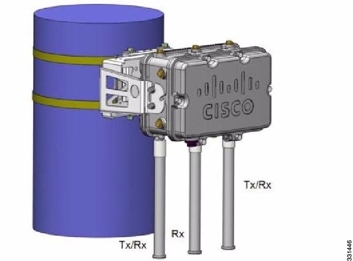
Two types of mounting configurations are available: the cable strand mount and the pole mount.
The 1552 models C and I access points are equipped with three new integrated dual-band antennas, with 2 dBi gain at 2.4 GHz and 4 dBi gain at 5 GHz. The antenna works in cable strand mount and low cost, low profile applications.
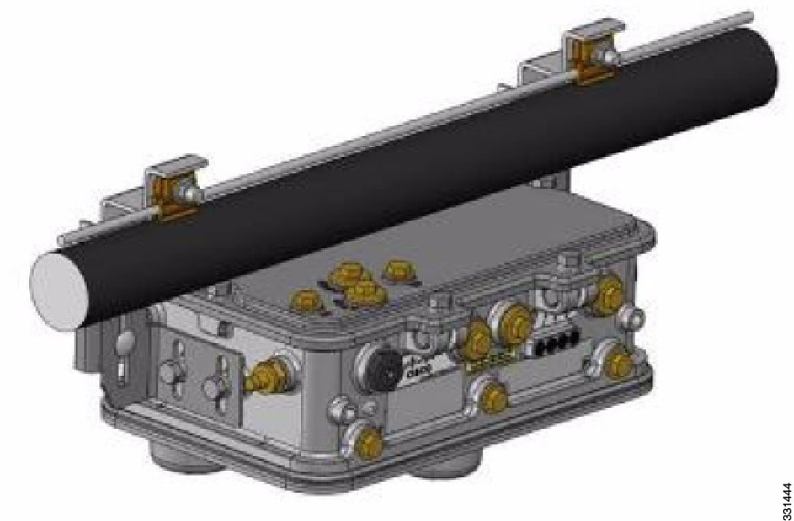
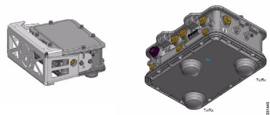
The 1552 E and H access points are equipped with three N-type radio frequency (RF) connectors (antenna ports 4, 5, and 6) on the bottom of the unit for external antennas to support multiple input multiple output (MIMO) operation as shown in the figure below. When using the optional Cisco Aironet AIR-ANT2547V-N Dual-Band Omnidirectional Antenna, the 2.4- and 5-GHz antennas connect directly to the access point. These antennas have 4 dBi gain at 2.4 GHz and 7 dBi gain at 5 GHz.
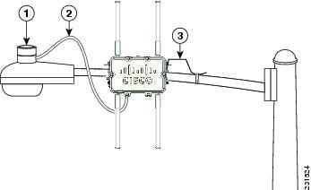
|
1 |
Outdoor light control |
3 |
6-AWG copper grounding wire |
|
2 |
Streetlight power tap adapter |
The AP1500 series was designed building on the long experience we have had in deploying outdoor access points over the past few years. This includes consideration for resistance to lightning effects. The AP1500 series employs some lightning arrestor circuitry on the Ethernet & Power ports. On input Ethernet port, Gas Discharge Tubes (GDT) are used on the Power Entry Module (PEM) to mitigate lightning effect. On the AC Power, GDTs are also used along with fuses to mitigate a high-current condition. For the DC power, a fuse is used to mitigate a high-current condition.
While not a common practice, users may want to consider adding additional lightning protection at the antenna ports for added protection.
Client Access Certified Antennas (Third-Party Antennas)
You can use third-party antennas with AP1500s. However, note the following:
-
Cisco does not track or maintain information about the quality, performance, or reliability of the noncertified antennas and cables.
-
RF connectivity and compliance is the customer’s responsibility.
-
Compliance is only guaranteed with Cisco antennas or antennas that are of the same design and gain as Cisco antennas.
-
Cisco Technical Assistance Center (TAC) has no training or customer history with regard to non Cisco antennas and cables.
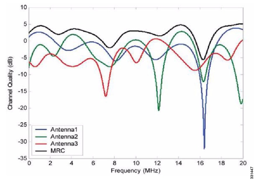
Maximum Ratio Combining
To understand how this works, consider a single transmitter 802.11a/g client sending an uplink packet to an 802.11n access point with multiple transceivers. The access point receives the signal on each of its three receive antennas.
Each received signal has a different phase and amplitude based on the characteristics of the space between the antenna and the client. The access point processes the three received signals into one reinforced signal by adjusting their phases and amplitudes to form the best possible signal. The algorithm used, called maximum ratio combining (MRC), is typically used on all 802.11n access points. MRC only helps in the uplink direction, enabling the access point to "hear" the client better.
For the 1550 Series
In the 1552 series mesh access point, MRC gain is different than the 1520 series mesh access points. The 1520 series access points do not have 802.11n functionality. In the 2.4-GHz band, it has only one transmitter and up to three receivers. Therefore, it is SIMO (Single in Multiple out) in 2.4 GHz. In the 5-GHz band, it has only one transmitter and one receiver. Therefore, it is SISO (Single in Single out) in the 5-GHz band. The MRC gain is important only for the 2.4-GHz radio in the 1552 access points. The MRC is not available for the 5-GHz radio. The 2.4-GHz radio has one Tx and up to three Rx antennas depending on the AP configuration.
In the 1522 access points, users have an option to use one, two, or three 2.4-GHz Rx antennas. With this option, users get around 3 dB MRC gain with 2 Rx antennas and a 4.5-dB MRC gain with 3 Rx antennas for data rates of 24 Mbps or higher.
For the 1552 access points, both the 2.4- and 5-GHz radios are 2x3 MIMO. Therefore, they have two transmitters and three receivers. Because the antennas are dual band and there is no option to have less than three Rx antennas, the MRC is added to the RX sensitivity always as it is embedded into the baseband chipset.
The number for typical Rx sensitivity in our customer data sheet assume 3 Rx antennas for both the 1520 and the 1550 series access points.
With the chipset used in the AP1520 series radios, there was a start-of-packet problem at lower data rates that wiped out the gain. Therefore, the MRC gain became useful from a data rate of 12 Mbps onwards in the 1520 series access points. This problem has been corrected in the current chipset used in the 1552 access points. The MRC gain has improved for lower data rates as well in the 1552 access points. You get a 4.7-dB improvement in sensitivity with the 2x3 MIMO radio over a 1x1 SISO implementation.
Table 1 and Table 2 list the MRC gain for the AP1552 11a/g and AP1552 11n respectively.
|
11a/g MCS (Mbps) |
Modulation |
MRC Gain from 3 RXs (dB) |
|---|---|---|
|
6 |
BPSK 1/2 |
4.7 |
|
9 |
BPSK 3/4 |
4.7 |
|
12 |
QPSK 1/2 |
4.7 |
|
18 |
QPSK 3/4 |
4.7 |
|
24 |
16QAM 1/2 |
4.7 |
|
36 |
16QAM 3/4 |
4.7 |
|
48 |
64QAM 2/3 |
4.7 |
|
54 |
64QAM 3/4 |
4.7 |
|
No. of Spatial Streams |
11n MCS |
Modulation |
MRC Gain from 3 RXs (dB) |
|---|---|---|---|
|
1 |
MCS 0 |
BPSK 1/2 |
4.7 |
|
1 |
MCS 1 |
QPSK 1/2 |
4.7 |
|
1 |
MCS 2 |
QPSK 3/4 |
4.7 |
|
1 |
MCS 3 |
16QAM 1/2 |
4.7 |
|
1 |
MCS 4 |
16QAM 3/4 |
4.7 |
|
1 |
MCS 5 |
64QAM 2/3 |
4.7 |
|
1 |
MCS 6 |
64QAM 3/4 |
4.7 |
|
1 |
MCS 7 |
64QAM 5/6 |
4.7 |
|
2 |
MCS 8 |
BPSK 1/2 |
1.7 |
|
2 |
MCS 9 |
QPSK 1/2 |
1.7 |
|
2 |
MCS 10 |
QPSK 3/4 |
1.7 |
|
2 |
MCS 11 |
16QAM 1/2 |
1.7 |
|
2 |
MCS 12 |
16QAM 3/4 |
1.7 |
|
2 |
MCS 13 |
64QAM 2/3 |
1.7 |
|
2 |
MCS 14 |
64QAM 3/4 |
1.7 |
|
2 |
MCS 15 |
64QAM 5/6 |
1.7 |
Note |
With two spatial streams, the MRC gain is halved, that is the MRC gain is reduced by 3 dB. This is because the system has 10 log (3/2 SS) instead of 10 log (3/1 SS). If there were to have been 3 SS with 3 RX, then the MRC gain would have been zero. |
Cisco 1500 Hazardous Location Certification
The standard AP1500 enclosure is a ruggedized, hardened enclosure that supports the NEMA 4X and IP67 standards for protection to keep out dust, damp and water.
Hazardous Certification (Class 1, Div 2, and Zone 2)
To operate in occasional hazardous environments, such as oil refineries, oil fields, drilling platforms, chemical processing facilities, and open-pit mining, special certification is required and the certification is labeled as Class 1, Div 2, or Zone 2.
Note |
For USA and Canada, this certification is CSA Class 1, Division 2. For Europe (EU), it is ATEX or IEC Class 1, Zone 2. |
Cisco has Hazardous Certified SKU for USA and EU: AIR-LAP1552H-x-K9. This SKU is modified, as per the certification requirements. The hazardous locations certificate requires that all electrical power cables be run through conduit piping to protect against accidental damage to the electrical wiring that could cause a spark and possible explosion. Access points for hazardous locations contain an internal electrical mounting connect that receives discrete wires from a conduit interface coupler entering from the side of the housing. After the electrical wiring is installed, a cover housing is installed over the electrical connector to prevent exposure to the electrical wiring. The outside of the housing has a hazardous location certification label (CSA, ATEX, or IEC) that identifies the type of certifications and environments that the equipment is approved for operation.
Note |
Power entry module for CSA (USA and Canada) is Power Entry Module, Groups A, B, C, and D with T5v(120° C) temp code. Power Entry Module for ATEX (EU) is Power entry module Groups IIC, IIB, IIA with T5 (120° C) temp code. |
Hazardous Certification (Div 1 > Div 2 and Zone 1 > Zone 2)
Class 1, Division 1/Zone 1 is for environments with full-time ignitable concentrations of flammable gases, vapors, or liquids. To meet the requirements of the Div 1 > Div 2 and Zone 1 > Zone 2 locations, we recommend a TerraWave Solutions CSA certified protective Wi-Fi enclosure (see Table 1).
|
Access Points |
Enclosure Part No |
Description |
|---|---|---|
|
Indoor Mesh Access Points |
Example: TerraWave XEP1242 for 1240 series. |
18 x12 x8 Protective Wi-Fi Enclosure that includes the Cisco 1242 Access Point |
|
Outdoor Mesh Access Points (1552) |
Example: TerraWave Part Number: XEP1522 |
18 x 12 x8 Protective Wi-Fi Enclosure that includes the Cisco 1522 Access Point |
For more information about the TerraWave enclosures, see http://www.tessco.com/yts/partner/manufacturer_list/vendors/terrawave/pdf/terrawavehazardouesenclosuresjan08.pdf
Table 2 lists the hardware features across different AP1500 models at a glance.
|
Features |
1552E |
1552H |
1552C |
1552I |
|---|---|---|---|---|
|
Number of radios |
2 |
2 |
2 |
2 |
|
External Antennas |
Yes |
Yes |
— |
— |
|
Internal Antennas |
— |
— |
Yes |
Yes |
|
CleanAir 2.4-GHz radio |
Yes |
Yes |
Yes |
Yes |
|
CleanAir 5-GHz radio |
— |
— |
— |
— |
|
Beam Forming (ClientLink) |
Yes |
Yes |
Yes |
Yes |
|
Fiber SFP |
Yes |
Yes |
— |
— |
|
802.3af PoE out port |
Yes |
Yes |
— |
— |
|
DOCSIS 3.0 Cable Modem |
— |
— |
Yes |
— |
|
HazLoc Class 1 Div 2/Zone 2 |
— |
Yes |
— |
— |
|
Battery backup option |
Yes |
Yes |
— |
— |
|
Power options |
AC, DC, Power Injector |
AC, DC, Power Injector |
40 to 90 VAC Power over Cable |
AC, DC |
|
Console Port Ext. Access |
Yes |
Yes |
Yes |
Yes |
Note |
PoE-in is not 802.3af and does not work with PoE 802.3af-capable Ethernet switch. It requires Power Injector. |

 Feedback