Overview

Overview of IoT Service (Wired)

Cisco Spaces enables end-to-end wired and wireless IoT device management, monitoring, and business outcome delivery at an enterprise scale using the following:

  • Cisco Spaces: IoT Service

  • Cisco Spaces: IoT Device Marketplace

  • Cisco Spaces App Center

In addition to serving as the management hub for wireless IoT devices, IoT Service can now integrate with Cisco Catalyst 9300 and 9400 Series Switches from Release 17.9.5 or later to receive IoT service (wired)  data from sensors, such as:

  • Passive infrared (PIR) sensors for presence detection

  • Sensors with telemetry such as temperature, humidity, CO2, and air quality for environmental analytics

  • Ethernet port information or status for occupancy and energy usage

  • Smart power distribution unit (PDUs) for energy efficiency tracking

Integrating IoT service (wired) with the Cisco Catalyst 9300 and 9400 Series Switches series platform requires the following:

  • Cisco Spaces: Connector

  • A IoT service (wired) gateway deployed and managed by Cisco Spaces

Cisco Catalyst 9300 and 9400 Series Switches can send critical IoT data to IoT service (wired). IoT service (wired) can then transmit the information to:

  • Business outcome applications on Cisco Spaces

  • Cisco Spaces App Center using the Firehose API

Figure 1. Data flow in IoT Service (Wired)

Compatibility matrix for IoT Service (Wired)

Application Name

Support for IoT Service (Wired)

Cisco Catalyst 9300 Series Switches

  • Cisco IOS XE Cupertino 17.9.5

  • Cisco IOS XE Dublin 17.12.4

Cisco Catalyst 9400 Series Switches

  • Cisco IOS XE Cupertino 17.9.5

  • Cisco IOS XE Dublin 17.12.4

Wired Docker Service

3.2. and later

Wired IOX Application

1.2.3 and later

IoT service (wired) is not supported with Cisco Spaces tenants or deployments leveraging the following configurations:

  • Connecting directly with controller

  • CMX Tethering

  • Sensor Connect for IoT (IoT Orchestrator)

Prerequisites for Cisco Spaces: IoT Service (Wired)

The following are the necessary prerequisites to get you started with Cisco Spaces: IoT Service (Wired):

  • Install Cisco Spaces: Connector in your network.

  • Configure a network with one or more Cisco Catalyst 9300 and 9400 Series Switches, Release 17.9.5 or later.

  • Switches must have Cisco DNA Advantage subscription. Cisco Spaces tenants must have either Spaces Extend, Act, Unlimited, or Spaces-Advantage license.

  • Deploy wired sensors in your network. See Compatibility matrix for IoT Service (Wired).

  • Ensure that Cisco Spaces is configured with maps either from Cisco Prime Infrastructure or Catalyst Center.

  • Configure AAA on aCisco Catalyst 9300 Series Switches or a  Cisco Catalyst 9400 Series Switches before adding it to Cisco Spaces by running these commands in:

    • aaa new-model

    • aaa authentication login default local

    • aaa authorization exec default local

  • Perform NTP synchronization across wireless controllers, Cisco Spaces: Connectors, and switches in the network.

  • Enable NETCONF on Cisco Catalyst 9300 or 9400 Series Switches on port 830, along with permission to use NETCONF.


    Note


    Cisco Catalyst 9300 and 9400 Series Switches require a privilege level 15 user to use and push configurations over NETCONF. Additionally, the user must be a password-protected user, because public-key authentication is not supported.

Design Prerequisites

Ensure you have the following information handy before proceeding:

Figure 2. Design Prerequisites
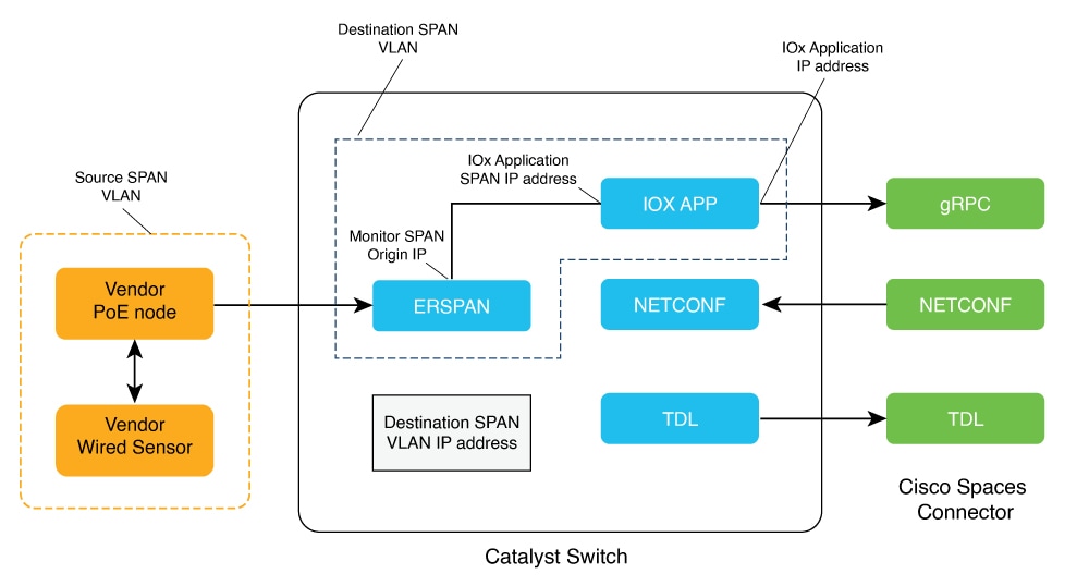
  • Destination SPAN VLAN: The VLAN used to send Encapsulated Remote Switched Port Analyzer (ERSPAN) traffic from Power over Ethernet (PoE) nodes to Cisco IOx App. You can use an existing VLAN or create a new one. This VLAN can also be local to the switch.

  • Destination SPAN VLAN IP address: This is the Switched Virtual Interface (SVI) or the IP address of the destination VLAN that can be used to route traffic. If you are using an existing VLAN, you can provide the same IP address. We recommend that you create a new VLAN so that you can keep the ERSPAN traffic local without impacting the existing configuration. Note that this VLAN is used only within the switch for the SPAN traffic.

  • Source SPAN VLAN list: List of VLANs to which the wired devices are connected. The traffic on these VLANs are monitored. If the wired devices are connected to multiple VLANs, enter the VLANs separated by a comma.

  • Monitor SPAN origin IP address: This is the source IP address of the monitor session. This can be from the SPAN VLAN. This can also be the same as the destination VLAN IP address.

  • IoX application Span IP Address

  • Application Cisco Spaces Connector VLAN: This is the VLAN on which the connector is reachable (for management or data). You can configure the Cisco IOx App's second interface to use this VLAN to send traffic to the connector. This VLAN can be the same as the wired PoE node VLAN. The connector must be permitted to accept communications from the Cisco IOx application.

  • DHCP: When enabled, DHCP allocates an IP address from the Application DNA Spaces Connector VLAN to the Cisco IOx App's second interface.

  • IoX application IP address: This is the IP address that you must manually configure for the Cisco IOx App's second interface, and is used to communicate with the Connector. This is not required if you select DHCP.

  • IoX application netmask: This is the IP subnet mask that you must manually configure for the Cisco IOx App's second interface, and is used to communicate with the connector. This is not required if you select DHCP.

  • IoX application gateway address: This is the IP address that you must manually configure for the Cisco IOx App's second interface, and is used to communicate with the connector. This is not required if you select DHCP.

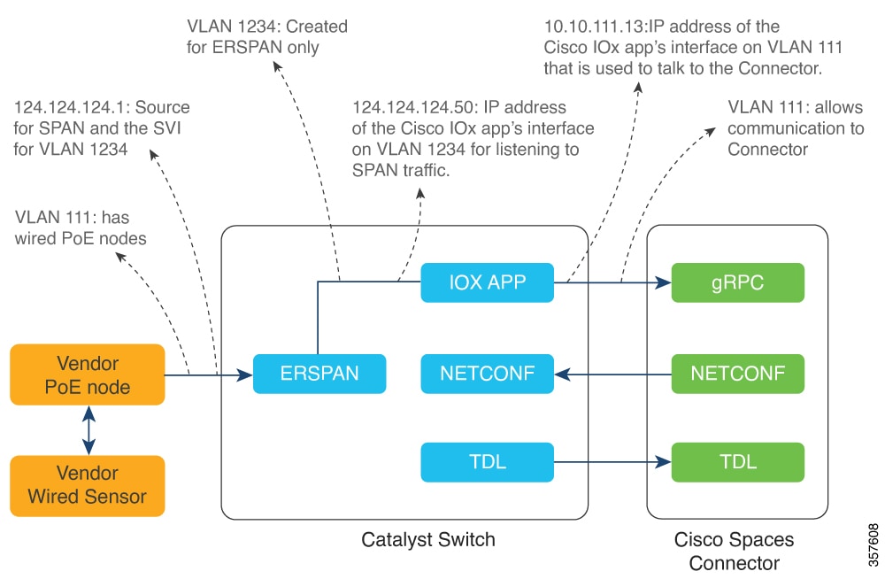
Figure 3. Sample Configuration

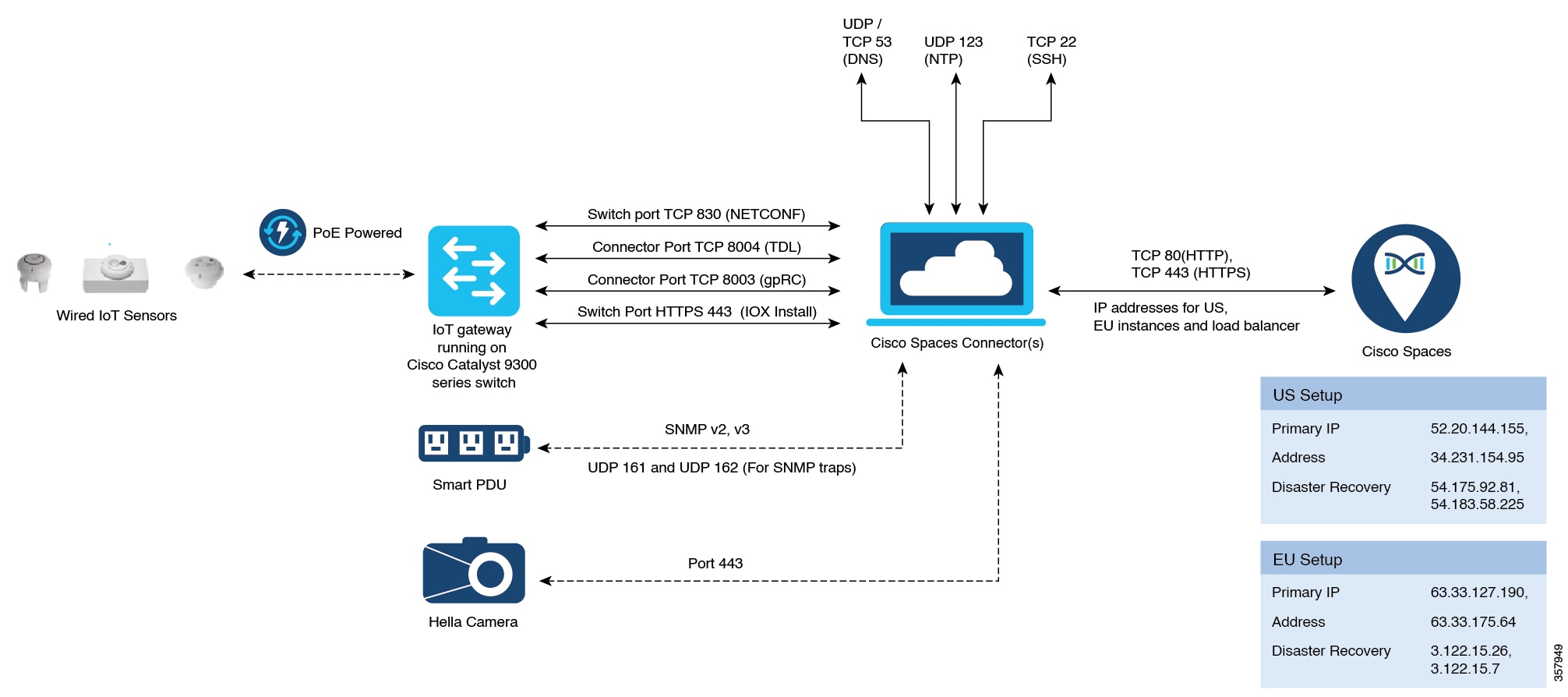
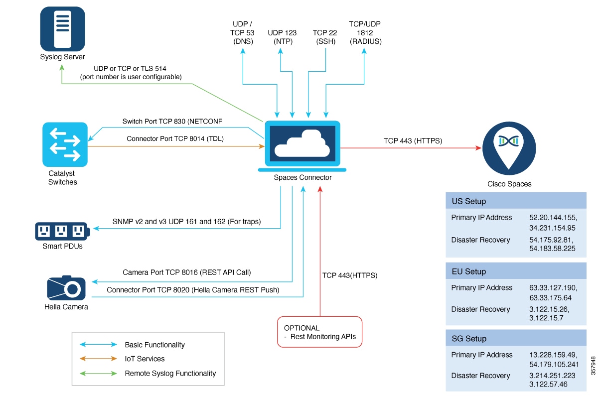
Open ports for IoT service (wired)

This section lists the connector ports that must be open for the proper functioning of each service or protocol.

Figure 4. Open Ports for IoT Service (Wired) with the IoT Gateway
Figure 5. Open Ports for IoT Service (Wired) without the IoT Gateway

Configure IoT service (wired) (GUI)

Enable the IoT Service (Wired) on a selected connector in Cisco Spaces dashboard.

Procedure


Step 1

On the Cisco Spaces dashboard, open the left-navigation pane. Click Setup and then choose Wired Network.

Step 2

In Configure Spaces Connector, select View Connectors.

Figure 6. View Connectors

Step 3

Select a connector 3 of your choice.

The connector details window appears.

Step 4

In the connector details window, click Add Services.

Figure 7. Add Services

Step 5

In the Add Service window, select IoT Wired and click Save.

Figure 8. Adding a Service
In the Connector Details window, the IoT Wired service appears as added.

Add switch to IoT service (wired) (GUI)

Add a Cisco switch to the IoT service using the Cisco Spaces dashboard for wired networks.

Procedure


Step 1

On the Cisco Spaces dashboard, open the left-navigation pane. Click Setup and then choose Wired Network.

Step 2

In Add switch, select Add Switches.

Figure 9. Add Switches

Step 3

Enter in the switch's information, make sure that the NETCONF user has privilege 15 and add a location.

Figure 10. Configuring the Switch

Configure switch via onboarding (GUI)

Configure a supported switch to act as a Wired Gateway for IoT Services through the onboarding workflow in the GUI.

Procedure


Step 1

Navigate to the IoT Services tab. Select About, and then select Activate IoT Services.

Note


If the switch is a VLAN Trunking Protocol (VTP) client, Spaces cannot configure the IOx app VLAN.

Figure 11. Activating IoT Services (Wired)

Step 2

Select Wired and press Next. After the Prerequisite Checks pass, select Click here for customization.

Figure 12. Selecting Wired Onboarding Path
Figure 13. Click here for customization option

Step 3

Select the connector to which you previously added your switch. The Activation Status should show as Activated. Then select Skip to Gateway Deployment.

Figure 14. Selecting Switch and Skipping to Gateway Deployment

Step 4

Select the supported switches on which you want to deploy the Wired Gateway.

Step 5

Select Static Note. DHCP is not currently supported.

Step 6

Enter the network information such as Source VLAN List, IOx VLAN, IOx Netmask, IOx Gateway Address. Select Next.

Figure 15. Configuring the Common Parameters for the Selected Switches

Step 7

Enter the IOx Application's IP address and click Next. Optionally, select the Show IoX Configurations and Show Advanced Configurations to view additional configuration options and information.

Figure 16. Configuring IOx Application IP Address

Step 8

After that, select View details > Wired > Wired Gateway to track the installation progress of the IOx application on your switch.

Figure 17. Deployment Status of IOx Application

Step 9

Once the Deployment Status is Activated, verify that the switch is acting as a Wired Gateway by navigating to IoT Services > IoT Gateways > Wired Gateway. View the Wired Gateways tab to confirm your switch appears in the list. Additionally, view the switch's request history to verify it shows SUCCESS.

Figure 18. List of Switches Acting as Wired Gateways
Figure 19. Verifying Successful IOx App Installation Via Request History

IoT Wired use cases

Sensor requirements

To ensure IoT Wired sensors properly report data, install the IOx app.

  • After verifying IOx app installation, navigate to IoT Services > Manage > Devices > Wired Sensors. If the third-party sensors' management software is properly configured, the sensor gateways and profiles appear automatically.

    Figure 20. Viewing wired sensors that are connected to the switch with IOx app installed
  • Click on Device IDs to view the different sensor profiles such as Humidity, Temperature, PIR.

Switchport Configurations

The Wired IOx Applicationis not required for 802.1x User Occupancy.

  • To ensure Wired 802.1x User Occupancy works properly, the switch ports must be configured appropriately. Port configuration varies depending on whether the end device is connected directly or through a Docking Station or Hub. You must also set a location for the switch. To set a location for a switch, navigate to Setup > Wired Network. You can add a new switch and assign a location or select View Switches to add a location to an existing switch.

    Example Configuration of a end device connected directly to a switch port configured for 802.1x.

    interface GigabitEthernet1/0/15
     switchport access vlan 239
     switchport mode access
     authentication port-control auto
     dot1x pae authenticator
    end
  • For devices that are connected to a switch via a Docking Station or Hub, the port must be configured with authentication timer inactivity <timer in seconds>.

    Example Configuration of a end device connected to a Docking Station/Hub that is then connected to a switch port configured for 802.1x

    interface GigabitEthernet1/0/16
     switchport access vlan 239
     switchport mode access
     authentication port-control auto
     authentication timer inactivity 300
     dot1x pae authenticator
    end

Verify authenticated 802.1x users via Cisco Spaces: Connector IoT Wired service

Access your connector using your local browser at https://<connector ip>.

Scroll down and select the expand option next to the IoT Service (Wired).

Figure 21. IoT wired service on connector UI

Next, scroll down to Authenticated Switch Ports. Check that you can see the users authenticated on the switch ports and confirm that the data is accurate.

Figure 22. Authenticated Switch Ports