Cisco Packet Data Serving Node (PDSN) Release 1.2 Feature in Cisco IOS Release 12.2(8)ZB
Available Languages
Table Of Contents
Cisco Packet Data Serving Node (PDSN) Release 1.2
PMTU Discovery by MobileIP Client
PDSN Cluster Controller / Member Architecture
Hardware IPSec Acceleration Using IPSec Acceleration Module—Static IPSec
Electronic Serial Number (ESN) in Billing
Features Available From Previous PDSN Releases
PDSN Clustering Peer-to-Peer and Controller / Member Architecture
Intelligent PDSN Selection and Load Balancing (Peer-to-Peer)
Related Features and Technologies
Supported Standards, MIBs, and RFCs
Creating the CDMA Ix Interface
Creating a Virtual Template Interface and Associating It With the PDSN Application
Enabling R-P Interface Signaling
Configuring User Session Parameters
Configuring AAA in the PDSN Environment
Configuring RADIUS in the PDSN Environment
Configuring Prepaid in the PDSN Environment
Enabling VPDN in a PDSN Environment
Configuring IP Sec for the Cisco PDSN
Configuring Proxy Mobile IP Attributes Locally
Configuring Mobile IP Security Associations
Configuring PDSN Cluster Controller in Release 1.2
Configuring PDSN Cluster Member in Release 1.2
Configuring Peer-to-Peer PDSN Selection
Configuring PDSN Accounting Events
Monitoring and Maintaining the PDSN
Cisco PDSN Configuration for Simple IP
Cisco PDSN Configuration for Simple IP with VPDN
Cisco PDSN Configuration for Mobile IP
Combined Configuration for Cisco PDSN
AAA Authentication and Authorization Profile
AAA Profiles for Various Service Types
cdma pdsn a11 dormant ppp-idle-timeout send-termreq
cdma pdsn accounting local-timezone
cdma pdsn accounting send cdma-ip-tech
cdma pdsn accounting send start-stop
cdma pdsn accounting time-of-day
cdma pdsn compliance iosv4.1 session-reference
cdma pdsn compliance is835a esn-optional
cdma pdsn ingress-address-filtering
cdma pdsn mobile-advertisement-burst
cdma pdsn retransmit a11-update
cdma pdsn selection load-balancing
cdma pdsn selection session-table-size
cdma pdsn timeout mobile-ip-registration
clear cdma pdsn cluster controller session records age
ip mobile authentication ignore-spi
show cdma pdsn accounting detail
show cdma pdsn accounting session
show cdma pdsn accounting session detail
show cdma pdsn accounting session flow
show cdma pdsn accounting session flow user
show cdma pdsn cluster controller
show cdma pdsn cluster controller configuration
show cdma pdsn cluster controller member
show cdma pdsn cluster controller session
show cdma pdsn cluster controller statistics
snmp-server enable traps ipmobile
debug cdma pdsn accounting flow
debug cdma pdsn accounting time-of-day
debug cdma pdsn resource-manager
debug cdma pdsn service-selection
Cisco Packet Data Serving Node (PDSN) Release 1.2
Feature History
12.2(8)BY
This feature was introduced on the Cisco 7200 Series Router.
12.2(8)ZB
This feature was introduced on the Cisco Catalyst 6500 Switch.
This document describes the Cisco Packet Data Serving Node (PDSN) software for use on the Cisco 7200 Series router, and the Cisco Multi-processor WAN Application Module (MWAM) that resides in the Cisco Catalyst 6500 Switch. It includes information on the features and functions of the product, supported platforms, related documents, and configuration tasks.
This document includes the following sections:
•
Supported Standards, MIBs, and RFCs
•
Feature Overview
A PDSN provides access to the Internet, intranets, and Wireless Application Protocol (WAP) servers for mobile stations using a Code Division Multiple Access 2000 (CDMA2000) Radio Access Network (RAN). The Cisco PDSN is a Cisco IOS software feature that runs on Cisco 7200 routers, and on MWAM cards on the 6500 routers, where it acts as an access gateway for Simple IP and Mobile IP stations. It provides foreign agent (FA) support and packet transport for virtual private networking (VPN). It also acts as an Authentication, Authorization, and Accounting (AAA) client.
The Cisco PDSN supports all relevant 3GPP2 standards, including those that define the overall structure of a CDMA2000 network, and the interfaces between radio components and the PDSN.
System Overview
CDMA is one of the standards for Mobile Station communication. A typical CDMA2000 network includes terminal equipment, mobile termination, base transceiver stations (BTSs), base station controllers (BSCs / PCFs), PDSNs, and other CDMA network and data network entities. The PDSN is the interface between a BSC / PCF and a network router.
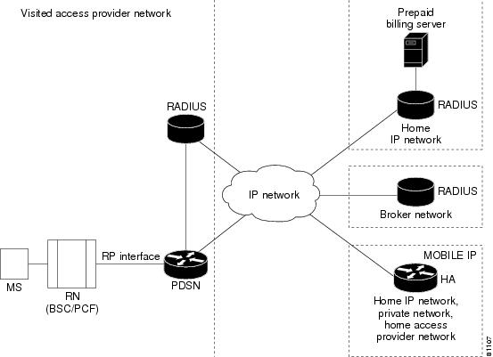
Figure 1 illustrates the relationship of the components of a typical CDMA2000 network, including a PDSN. In this illustration, a roaming mobile station user is receiving data services from a visited access provider network, rather than from the mobile station user's subscribed access provider network.
Figure 1 The CDMA Network
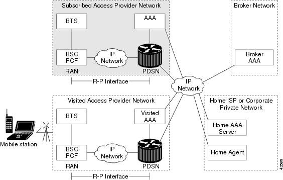
As the illustration shows, the mobile station, which must support either Simple IP or Mobile IP, connects to a radio tower and BTS. The BTS connects to a BSC, which contains a component called the Packet Control Function (PCF). The PCF communicates with the Cisco PDSN through an A10/A11 interface. The A10 interface is for user data and the A11 interface is for control messages. This interface is also known as the RAN-to-PDSN (R-P) interface. For the Cisco PDSN Release 1.2, you must use a Fast Ethernet (FE) interface as the R-P interface on the 7200 platform, and a Giga Ethernet (GE) interface on the MWAM platform.
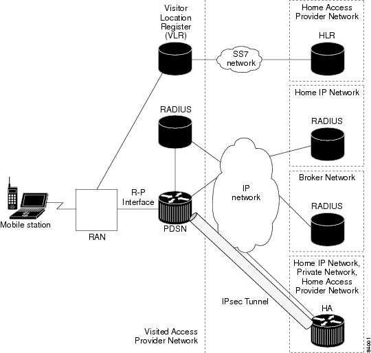
Figure 2 illustrates the communication between the RAN and the Cisco PDSN.
Figure 2 RAN-to-PDSN Connection: the R-P Interface

The IP networking between the PDSN and external data networks is through the PDSN-to-intranet/Internet (Pi) interface. For the Cisco PDSN Release 1.2, you can use either an FE or GE interface as the Pi interface.
For "back office" connectivity, such as connections to a AAA server, or to a RADIUS server, the interface is media independent. Any of the interfaces supported on the Cisco 7206 can be used to connect to these types of services; however, Cisco recommends that you use either an FE or GE interface.
How PDSN Works
When a mobile station makes a data service call, it establishes a Point-to-Point Protocol (PPP) link with the Cisco PDSN. The Cisco PDSN authenticates the mobile station by communicating with the AAA server. The AAA server verifies that the user is a valid subscriber, determines available services, and tracks usage for billing.
The method used to assign an IP address and the nature of the connection depends on service type and network configuration. Simple IP operation and Mobile IP operation are referred to as service types. The service type available to a user is determined by the mobile station, and by the type of service that the service provider offers. In the context of PDSN, a mobile station is the end user in both Simple IP and Mobile IP operation.
Once the mobile station is authenticated, it requests an IP address. Simple IP stations communicate the request using the Internet Protocol Control Protocol (IPCP). Mobile IP stations communicate the request using Mobile IP registrations.
The following sections describe the IP addressing and communication levels for each respective topic:
•
Cisco PDSN Simple IP
With Simple IP, a service provider's Cisco PDSN assigns a dynamic or static IP address to the mobile station during the PPP link setup. The mobile station retains this IP address as long as it is served by a radio network that has connectivity to the address-assigning PDSN.
Therefore, as long as the mobile station remains within an area of RANs that is served by the same PDSN, the MS can move or roam inside the coverage area and maintain the same PPP links. If the mobile station moves outside the coverage area of the given PDSN, the mobile station is assigned a new IP address, and any application-level connections are terminated.

Note
Figure 3 illustrates the placement of the Cisco PDSN in a Simple IP scenario.
Figure 3
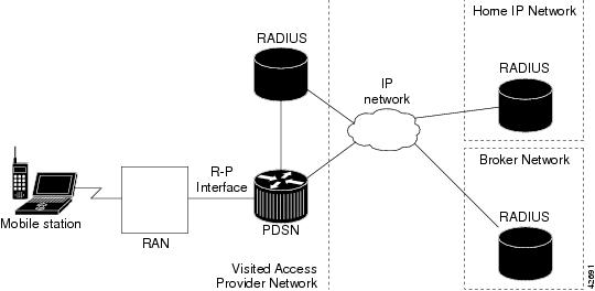
CDMA Network - Simple IP Scenario
Cisco PDSN Simple IP with VPDN Scenario
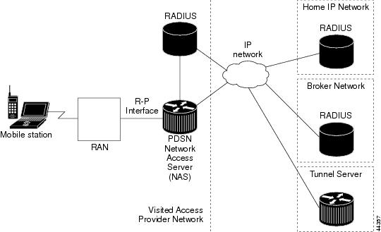
A VPDN allows a private network dial-in service to span to remote access servers called Network Access Servers (NAS). Figure 4 illustrates a VPDN connection in the PDSN environment with Simple IP. In this scenario, the PDSN is acting as the NAS.
Figure 4 CDMA Network —Simple IP with VPDN Scenario
A VPDN connection is established in the following order:
1.
2.
3.
The PPP client is forwarded through a Layer 2 Tunneling Protocol (L2TP) tunnel over User Datagram Protocol (UDP).
4.
Cisco PDSN Mobile IP
With Mobile IP, the mobile station can roam beyond the coverage area of a given PDSN and still maintain the same IP address and application-level connections.
Figure 5 shows the placement of the Cisco PDSN in a Mobile IP scenario.
Figure 5
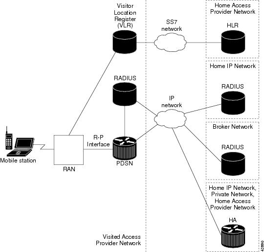
CDMA Network —Mobile IP Scenario
The communication process occurs in the following order:
1.
2.
As part of the registration process, the HA creates a binding table entry to associate the mobile station's home address with its Care-of address.
Note
3.
4.
5.
6.
7.
Note
PMTU Discovery by MobileIP Client
FTP upload and ping from the end node may fail when PMTU Discovery (done by setting the DF bit) is done by a MobileIP client (an end node) for packet sizes of about 1480. Due to failure of PMTUD algorithm, the IP sender will never learn the smaller path MTU, but will continue unsuccessfully to retransmit the too-large packet, until the retransmissions time out.
Please refer to http://www.cisco.com/warp/public/105/38.shtml#2000XP for disabling PMTUD for windows 2000/XP platforms.
Cisco PDSN Proxy Mobile IP
Currently, there is a lack of commercially-available Mobile IP client software. Conversely, PPP, which is widely used to connect to an Internet Service Provider (ISP), is ubiquitous in IP devices. As an alternative to Mobile IP, you can use Cisco's proxy Mobile IP feature. This capability of the Cisco PDSN, which is integrated with PPP, enables a Mobile IP FA to provide mobility to authenticated PPP users.
Note
The communication process occurs in the following order:
1.
2.
3.
4.
5.
6.
PDSN on MWAM
The MWAM will support the feature set of PDSN R1.2. The funtionality remains the same as it would on the Cisco 7200 platforms. The significant difference between PDSN on the 7200 and on the MWAM is that a Catalyst 6500 chassis will support a maximum of 6 application modules. Each application module supports 5 IOS images, each with access to 512 Megabytes of RAM. Up to five of these images can function as a PDSN.
Additionally, instances of the cluster controller functionality will be configured as required. One active and one standby controller are required for each increment of 200,000 sessions. Each image supports 20,000 sessions. For every 10 PDSNs configured in the chassis, one active and one standby controller is required. Internal to the chassis, the PDSN images are configured on the same VLAN in order to support the Controller-Member architecture (although the architecture itself does not require this). Load balancing external to the chassis is determined by the physical proximity of the chassis and the network architecture. It is possible that you require both a VLAN approach, and a more traditional routed approach.
Features
This section describes the following key features of the Cisco PDSN Release 1.2:
•
•
•
•
•
Note
Note
PDSN Cluster Controller / Member Architecture
Release 1.2 introduces a new controller-member architecture that improves cluster capacity by reducing the resource utilization on the PDSN cluster member.
This new controller-member mode designates certain nodes as controllers responsible for performing PDSN selection, and for maintaining the global session tables. Each member node maintains information only about the sessions that are terminated on that node. Controllers can be redundant with all session information synchronized between them, and they monitor the state of all nodes to detect the failure of a member or another controller.
When a PDSN cluster operates in the controller-member mode, controllers are dedicated to the PDSN selection function, and do not terminate bearer sessions.
Note
For information on redundancy and load balancing in the PDSN Release 1.2, see the "PDSN Clustering Peer-to-Peer and Controller / Member Architecture" section.
Note
PDSN MIB Enhancement
The PDSN 1.2 software release allows you to manage the Cisco PDSN with Cisco Works 2000 network management system using SNMP. In addition to the standard 7200 and 6500 MIBS, the Cisco CDMA PDSN MIB (CISCO_CDMA_PDSN_MIB.my) is part of the PDSN solution. The Cisco PDSN MIB also supports the following features
•
–
–
–
–
–
•
a.
b.
Prepaid Billing
The Cisco PDSN 1.2 software release provides real-time monitoring and rating of data calls for prepaid users. The prepaid billing solution for the PDSN is based on the RADIUS (AAA) server, and takes advantage of the existing flow-based accounting functionality. The prepaid billing feature requires the RADIUS server to interface with a Prepaid Billing Server (PBS) to relay real-time billing information between the PDSN and the PBS. A third-party Prepaid Billing Server controls the real-time rating of data calls and maintains balances in users' accounts. Cisco does not supply the PBS.
The prepaid billing feature provides the following services:
•
•
•
Figure 6 shows the network reference architecture for prepaid service. The PBS resides in the mobile station's home network and is accessed by the home RADIUS server. A Cisco Access Registrar (AR) with prepaid functionality can be used as the home RADIUS server to provide service to prepaid and non-prepaid users.
Figure 6
PDSN Prepaid Billing Architecture
For roaming users, the local RADIUS server in the visited network forwards AAA requests to the home RADIUS server, using a broker RADIUS server if required. For roaming prepaid users, this requires that the local and broker AAA servers forward the new vendor specific prepaid accounting attributes transparently to the home RADIUS server.
In existing networks, where the home RADIUS server does not support the interface to the Prepaid Billing Server, AR can be placed in front of the home RADIUS server to act as a proxy. In this case AR forwards all authorization and accounting messages to /from the home RADIUS server and communicates with the PBS. This scenario is relevant if an operator already has a RADIUS server.
While this architecture does impose some additional requirements on the RADIUS server, the interface towards the PDSN does not change.
It is possible that an operator may want to use an existing WIN or IN based prepaid billing server. In this situation, the PBS will interface to the external prepaid billing server.
Accounting Records
The PDSN will continue to generate per flow accounting records in the same way as it does for non-prepaid users. However, the last Accounting Stop Request for a flow will contain the new prepaid Vendor Specific Attributes (VSAs) for reporting the final usage.
How Prepaid Works in PDSN
When a prepaid mobile user makes a data service call, the MS establishes a Point-to-Point Protocol (PPP) link with the Cisco PDSN. The Cisco PDSN authenticates the mobile station by communicating with the AAA server. The AAA server verifies that the user is a valid prepaid subscriber, determines what services are available for the user, and tracks usage for billing.
The methods used to assign an IP address and the nature of the connection are similar to those discussed in the "How PDSN Works" section.
The following sections describe the IP addressing and communication levels in the prepaid environment for each respective topic:
Prepaid Simple IP Call Flow
In the following scenario, the prepaid user has sufficient credit and makes a Simple IP data call. The user disconnects at the end of the call.
Step 1
Step 2
Step 3
Step 4
Step 5
Step 6
Step 7
Step 8
Step 9
Step 10
Step 11
Step 12
Step 13
Prepaid Mobile IP Call Flow
In the following scenario, the prepaid user makes a Mobile IP data call. The user runs out of quota during the mobile IP data session and the PDSN disconnects the call. The call flow shows a single Mobile IP flow; however, additional flows are established and handled in a similar manner when the MS sends additional Mobile IP Registration Requests.
Step 1
Step 2
Step 3
Step 4
Step 5
Step 6
Step 7
Step 8
Step 9
Step 10
Step 11
Step 12
Step 13
Step 14
Step 15
Note
3 DES Encryption
The Cisco PDSN 1.2 release include 3DES encryption, which supports IPSec on PDSN. To accomplish this on the 7200 platform, Cisco supplies an SA-ISA card for hardware provided IPsec. IPSec on the MWAM platform requires you to use a Cisco VPN Acceleration Module.
This feature allows VPDN traffic and Mobile IP traffic (between the PDSN Home Agent) to be encrypted. In this release the PDSN requires you to configure the parameters for each HA before a mobile ip data traffic tunnel is established between the PDSN and the HA.
Note
Note
Mobile IP IPSec
The Internet Engineering Task Force (IETF) has developed a framework of open standards called IP Security (IPSec) that provides data confidentiality, data integrity, and data authentication between participating peers. IPSec provides these security services at the IP layer; it uses Internet Key Exchange (IKE) to handle negotiation of protocols and algorithms based on local policy, and to generate the encryption and authentication keys to be used by IPSec. IPSec can be used to protect one or more data flows between a pair of hosts, between a pair of security gateways, or between a security gateway and a host.
IS-835-B specifies three mechanisms for providing IPSec security:
•
•
•
Note
Hardware IPSec Acceleration Using IPSec Acceleration Module—Static IPSec
Note
IPSec-based security may be applied on tunnels between the PDSN and the HA depending on parameters received from Home AAA server. A single tunnel may be established between each PDSN-HA pair. It is possible for a single tunnel between the PDSN-HA pair to have three types of traffic streams: Control Messages, Data with IP-in-IP encapsulation, and Data with GRE-in-IP encapsulation. All Traffic carried in the tunnel will have the same level of protection provided by IPSec.
IS-835-B defines MobileIP service as described in RFC 2002; the Cisco PDSN provides Mobile IP service and Proxy Mobile IP service.
In Proxy Mobile service, the Mobile-Node is connected to the PDSN/FA through Simple IP, and the PDSN/FA acts as Mobile IP Proxy for the MN to the HA.
Once Security Associations (SAs, or tunnels) are established, they remain active until there is traffic on the tunnel, or the lifetime of the SAs expire.
Figure 7 illustrates the IS-835-B IPSec network topology.
Figure 7 IS-835-B IPSec Network
Hardware IPSec acceleration of 8000 IPSec tunnels per chassis is available through the use of the Cisco VPN Acceleration Module. Refer to the xxxxx for more information.
Note
Conditional Debugging
PDSN Release 1.2 software introduces conditional debugging based on the Mobile Subscriber ID (MSID) into the CDMA subsystem by using the existing IOS debug condition of the Cisco CLI. The calling option of the CLI is used to specify the MSID (for example, debug condition calling 00000000011124).
To enable conditional debugging, set the condition and enable the required IOS debugs. Some conditional debugging based on the Network Access Identifier (NAI) is already supported by various IOS modules (for example, PPP using the username option). To enable conditional debugging for a specific NAI, use the following command:
debug condition username username
This release provides conditional debugging support for the following PDSN CLI commands:
•
•
•
The a11 debugs additionally support msid-based debugging using the following individual CLI commands:
•
•
•
Refer to "Using Debug Commands for PDSN Release 1.2" for more information about conditional debugging in PDSN Release 1.2.
Electronic Serial Number (ESN) in Billing
The ESN is a unique identifier for a piece of equipment, such as of a mobile device, and is used during the authentication process. The ESN is parameter a2 of the R-P Session Setup airlink record, and parameter A2 in the PDSN Usage Data Record (UDR). Both parameters are introduced in this release.
The PDSN accepts the parameter a2, and puts it as A2 into a User Data Record.
This feature is supported in the Cisco Access Registrar.
1xEV-DO Support
The Cisco PDSN 1.2 release supports Evolution-Data Optimized (1xEV-DO). 1xEV-DO offers high performance, high-speed, high-capacity wireless Internet connectivity, and is optimized for packet data services. It can transport packet data traffic at forward peak rates of 2.4 Mbps, which is much higher than the current 1xRTT peak rate of 144 kbps.
PDSN R1.2 support for 1xEV-DO technology includes the following enhancements:
•
•
Features Available From Previous PDSN Releases
The following features were introduced in previous PDSN software releases, and are still supported in 1.2.
Integrated Foreign Agent (FA)
The FA is an essential component to mobility, because it allows a mobile station to remotely access services provided by the station's home network. The Cisco PDSN provides an integrated FA. The FA communicates with any standard HA including the Cisco IOS-based HA.
AAA Support
The Cisco PDSN provides an authentication client that communicates with any standard AAA server, including Cisco Access Registrar, to authenticate the mobile station. It uses the mobile stations' name (NAI) for authentication of the user with the local AAA server.
•
–
–
–
Note
•
–
–
•
–
–
–
•
–
–
–
–
The Cisco PDSN also supports service provisioning using AAA servers and a user service profile. This profile is defined by the user's home network. It is referenced by the NAI. It is typically stored in the AAA server in the user's home network, along with the user authentication information, and is retrieved as part of authorization reply.
Packet Transport for VPDN
The Cisco PDSN supports the transport of VPDN packets. If the operator offers VPDN services, the mobile station can securely access private resources through a public Internet or dedicated links. The VPDN tunnel extends from the PDSN/FA to the home IP network. The home IP network is the IP network associated with the NAI.
Proxy Mobile IP
With Proxy Mobile IP as part of the PPP link initiation, the PDSN registers with a HA on behalf of the mobile station. It obtains an address from the HA and forwards that address to the mobile station as part of IPCP during PPP initialization.
Multiple Mobile IP Flows
The Cisco PDSN allows multiple IP access points from the same mobile station, as long as each IP flow registers individually (each IP flow requires a unique NAI). This enables multiple IP hosts to communicate through the same mobile access device and share a single PPP connection to the operator's network. For accounting purposes, it is important that the PDSN generate separate usage data records (UDRs) for each flow to the AAA server.
Redundancy and Load Balancing
This section provides information about Intelligent PDSN Selection and Load Balancing for both the Controller - Member cluster model, and for the Peer-to-Peer cluster model.
PDSN Clustering Peer-to-Peer and Controller / Member Architecture
The PDSN Clustering Peer-to-Peer Architecture (or PDSN Intelligent Selection and Load Balancing feature), implemented in the PDSN R1.1 software release, functions in a peer-to-peer model. All the PDSNs in the cluster share their load and served MSID, and multicast their load and MSID to all other PDSNs in the cluster. This drains resources because large MSID tables need to be stored on all the PDSNs, and because a large amount of traffic is generated to exchange the information among the cluster members. This results in constraints on the cluster size.
In the Cisco PDSN 1.2 release, you can choose between Peer-to-Peer clustering, or Controller-Member clustering. In Controller-Member clustering, a controller maintains load and session (such as A10 connection) information for each member in the cluster, and performs member selection for load-balancing or inter-PDSN handoff avoidance. The controller identifies the operational state of each member and detects the failure of a member, or the failure of another controller. A member notifies the controller about its load and session information.
Note
Note
Figure 8 illustrates the Controller-Member architecture on the 6500-based MWAM platform. This illustration depicts two PDSN clusters with two primary and two backup controllers, and their corresponding members.
Figure 8 PDSN Controller -Member Architecture
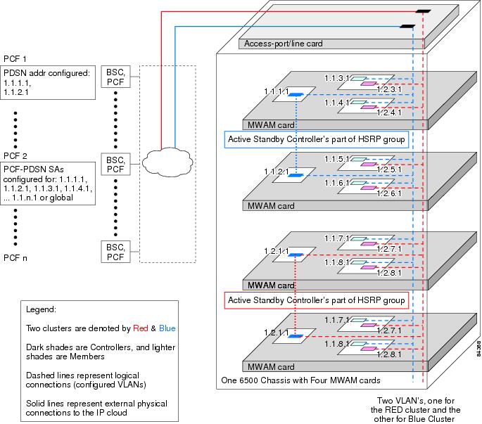
for MWAM on the Catalyst 6500
PDSNs that are designated as controllers, perform member PDSN selection and load balancing. The following list describes the major functions of the controllers:
•
•
•
•
•
•
•
Redundancy
Cluster redundancy is based on the premise that only one PDSN might fail at any given time. Two controllers are configured as an HSRP group: One controller is active, the other standby. Controllers have redundancy and members have load sharing.
Load Sharing
Cluster member loadsharing is an N+1 scheme. If a member fails, the established sessions will be lost, but the overall group capacity allows sessions to be re-established with the other group members. Additionally, redundancy is also enhanced because cluster members no longer have to be network neighbors.
Controllers exchange information over an ethernet link. Controllers and members exchange information over a unicast interface link where members address messages to the HSRP group address of the controllers. The members in a PDSN cluster do not need to be network neighbors; they can be attached anywhere in the IP network.
Adding an additional controller to a cluster is simplified by auto-configuration of the controller in the cluster. This is possible by configuring the additional controller for HSRP. The newly-added controller will automatically synchronize with the active controller. Similarly, when a new member is added to the cluster, auto-configuration for the member occurs in all cluster controllers.
PDSN Cluster Member Selection
Selection of a cluster member by the controller is based on a load factor. Load factor is a computed value by session load and CPU load on a member. The controller attempts to assign sessions to a member that has smallest load factor so that data connections are evenly distributed over members in the cluster as much as possible.
If an A11 Registration Request is received indicating a handoff, a member that is already serving the session is selected by the controller.
Load Balancing
A controller maintains load information for all members in the cluster in order to perform PDSN Cluster Member selection. This load information is transferred from the members to the controller under the following conditions:
•
•
•
The session and member records are synchronized between the active and standby controllers as needed. Since both active and standby controller maintain session and load information for all the members of that cluster, failure of a controller does not result in the loss of any session or load information.
Intelligent PDSN Selection and Load Balancing (Peer-to-Peer)
The Cisco Intelligent PDSN Selection (Peer-to-Peer) feature in Release 1.2 allows you to group a number of Cisco PDSNs into clusters that can exchange session information for performance and load-balancing purposes. Each Cisco PDSN in a group maintains a table that contains information for the entire group. Using PDSN clusters, minimizes inter-PDSN handoff, provides intelligent load-balancing, and ensures high availability.
To distribute session information, each PDSN sends a broadcast to the Mobile IP multicast address when a session is created or ended. The IP address of the originating PDSN and the MSID are encoded in the Mobile IP messages. Each PDSN in a group updates its session table upon receiving the broadcast.
When a session request is received from the PCF by the Cisco PDSN, the PDSN checks its own session list for an existing session, and also checks session lists within its PDSN group. If it determines that a session exists with another PDSN, it redirects the PCF to that PDSN. This redirection helps to avoid dropping the IP address and, thereby, avoids dropping any existing communication.
If the session does not exist with any other PDSN, the receiving PDSN uses a load-balancing mechanism to determine the appropriate PDSN to use for session establishment. With load balancing, the receiving PDSN looks for the least utilized PDSN in the entire cluster. If the number of active PPP links on that PDSN is some factor less than the number of PPP links on the receiving PDSN, the request will be forwarded. The factor for determining whether the PPP link is forwarded is calculated as a percentage (number of active PPP links vs. total number of possible PPP links).
Load Balancing
For a new packet data session, one PDSN may direct a connection request to another less "loaded" PDSN within the cluster by proposing the address of that PDSN to the PCF. Such redirection of A10 connection requests is performed among lesser loaded PDSNs in a round-robin manner. In PDSN software releases prior to Release 1.1, the load balancing threshold was implemented in terms of a session count differential. Starting in Release 1.1, the threshold is configured in terms of a load factor—the ratio of number of sessions supported and total session capacity of the PDSN. In future releases, other factors (such as QoS, session throughput considerations, CPU load, memory utilization) might also be considered as parameters used to determine of load factor of a PDSN.
Scalability
In this release the PDSN uses a new scalability feature that allows PPP sessions to run on virtual-access subinterfaces that can support up to 20000 sessions.
Note
Note
Note
High Availability
Overview
High availability allows you to minimize the switchover time from the active supervisor engine to the standby supervisor engine if the active supervisor engine fails.
Prior to this feature, fast switchover ensured that a switchover to the standby supervisor engine happened quickly. However, with fast switchover, because the state of the switch features before the switchover was unknown, you had to re-initialize and restart all the switch features when the standby supervisor engine assumed the active role.
High availability removes this limitation; high availability allows the active supervisor engine to communicate with the standby supervisor engine, keeping feature protocol states synchronized. Synchronization between the supervisor engines allows the standby supervisor engine to take over in the event of a failure.
In addition, high availability provides a versioning option that allows you to run different software images on the active and standby supervisor engines.
For high availability, a system database is maintained on the active supervisor engine and updates are sent to the standby supervisor engine for any change of data in the system database. The active supervisor engine communicates and updates the standby supervisor engine when any state changes occur, ensuring that the standby supervisor engine knows the current protocol state of supported features. The standby supervisor engine knows the current protocol states for all modules, ports, and VLANs; the protocols can initialize with this state information and start running immediately.
The active supervisor engine controls the system bus (backplane), sends and receives packets to and from the network, and controls all modules. Protocols run on the active supervisor engine only.
The standby supervisor engine is isolated from the system bus and does not switch packets. But it does receive packets from the switching bus to learn and populate its Layer 2 forwarding table for Layer 2-switched flows. The standby supervisor engine also receives packets from the switching bus to learn and populate the Multilayer Switching (MLS) table for Layer 3-switched flows. The standby supervisor engine does not participate in forwarding any packets and does not communicate with any modules.
If you enable high availability when the standby supervisor engine is running, image version compatibility is checked and if found compatible, the database synchronization is started. High availability compatible features continue from the saved states on the standby supervisor engine after a switchover.
When you disable high availability, the database synchronization is not done and all features must restart on the standby supervisor engine after a switchover.
If you change high availability from enabled to disabled, synchronization from the active supervisor engine is stopped and the standby supervisor engine discards all current synchronization data.
If you change high availability from disabled to enabled, synchronization from the active to standby supervisor engine is started (provided the standby supervisor engine is present and its image version is compatible).
NVRAM synchronization occurs irrespective of high availability being enabled or disabled (provided there are compatible NVRAM versions on the two supervisor engines).
If you do not install a standby supervisor engine during system bootup, the active supervisor engine detects this and the database updates are not queued for synchronization. Similarly, when you reset or remove the standby supervisor engine, the synchronization updates are not queued and any pending updates in the synchronization queue are discarded. When you hot insert or restart a second supervisor engine that becomes the standby supervisor engine, the active supervisor engine downloads the entire system database to the standby supervisor engine. Only after this global synchronization is completed, the active supervisor engine queues and synchronizes the individual updates to the standby supervisor engine.
Note
For more information about High Availability, including configuration details, and information about power management, refer to the "PDSN Clustering Peer-to-Peer and Controller / Member Architecture" section, as well as the documents at the following urls:
•
–
•
–
–
Related Features and Technologies
•
•
•
•
•
Related Documents
For additional information about the Cisco PDSN Release 1.2 software, refer to the following documents:
•
For more information about:
•
•
•
•
•
•
Supported Platforms
The Cisco PDSN for MWAM release is a feature enhancement for the Cisco 7206 router and the Multi-Processor WAN Application Module (MWAM) card that resides on the Cisco Catalyst 6500 switch. Refer to the following document for more information regarding the respective platforms:
•
Supported Standards, MIBs, and RFCs
Standards
•
•
•
MIBs
•
•
•
•
•
•
•
•
For descriptions of supported MIBs and how to use MIBs, see the Cisco MIB web site on CCO at http://www.cisco.com/public/sw-center/netmgmt/cmtk/mibs.shtml.
RFCs
•
•
•
•
•
•
•
•
•
•
•
•
•
•
•
•
•
•
•
Configuration Tasks
This section describes the steps for configuring the Cisco PDSN software on both the 7200 and MWAM platforms. Prior to configuring instances of the PDSN on MWAM application cards, you must create a base Catalyst 6500 configuration. Refer to the Cisco Multi-processor WAN Application Module Installation and Configuration Note for more information.
Configuring the PDSN Image
The Cisco PDSN can provide four classes of user services: Simple IP, Simple IP with VPDN, Mobile IP, and proxy Mobile IP. The following sections describe the configuration tasks for implementing Cisco PDSN. Each category of tasks indicates whether the tasks are optional or required.
R-P Interface Configuration Tasks (Required for all classes of user services)
The following tasks establish the R-P interface, also referred to as the A10/A11 interface. Configuring the R-P interface is required in all 7200 platform configuration scenarios.
To configure the R-P interface, complete the following tasks:
•
•
•
•
User Session Configuration Tasks (Optional)
To configure the user session, complete the following task.
•
AAA and RADIUS Configuration Tasks (Required for All Scenarios)
To configure the AAA and RADIUS in the PDSN environment, complete the following tasks.
•
•
Prepaid Configuration Tasks (Available only on C-6 images)
•
VPDN Configuration Tasks (Required for Simple IP with VPDN Scenario)
To configure the VPDN in the PDSN environment, complete the following task:
•
Mobile IP Configuration Tasks (Required for Mobile IP)
To configure Mobile IP on the PDSN, complete the following task:
•
•
PDSN Selection Configuration Tasks (Optional)
To configure PDSN selection, complete the following tasks:
•
•
•
Network Management Configuration Tasks (Required for Network Management in Any Scenario)
To configure network management, complete the following task:
Tuning, Verification, and Monitoring Tasks (Optional)
To tune, verify, and monitor PDSN elements, complete the following tasks:
•
•
Enabling PDSN Services
To enable PDSN services, use the following commands in global configuration mode:
Creating the CDMA Ix Interface
To create the CDMA Ix interface, use the following commands in global configuration mode:
Creating a Loopback Interface
We recommend that you create a loopback interface and then associate the loopback interface IP address to the virtual template, rather than directly configuring an IP address on the virtual template.
To create a loopback interface, use the following commands in global configuration mode:
Creating a Virtual Template Interface and Associating It With the PDSN Application
Creating a virtual template interface allows you to establish an interface configuration and apply it dynamically.
To create a virtual template interface that can be configured and applied dynamically, use the following commands in global configuration mode:
Enabling R-P Interface Signaling
To enable the R-P interface signaling, use the following commands in global configuration mode:
Configuring User Session Parameters
To configure user session parameters, use the following commands in global configuration mode:
Configuring AAA in the PDSN Environment
Access control is the way you manage who is allowed access to the network server and the services they are allowed to use. AAA network security services provide the primary framework through which you set up access control on your router or access server. For detailed information about AAA configuration options, refer to the "Configuring Authentication," and "Configuring Accounting" chapters in the Cisco IOS Security Configuration Guide.
To configure AAA in the PDSN environment, use the following commands in global configuration mode:
Configuring RADIUS in the PDSN Environment
RADIUS is a method for defining the exchange of AAA information in the network. In the Cisco implementation, RADIUS clients run on Cisco routers and send authentication requests to a RADIUS server that contains all user authentication and network server access information. For detailed information about RADIUS configuration options, refer to the "Configuring RADIUS" chapter in the Cisco IOS Security Configuration Guide.
To configure RADIUS in the PDSN environment, use the following commands in global configuration mode:
Configuring Prepaid in the PDSN Environment
Currently, there are no configuration commands for prepaid. To configure prepaid, ensure that you include "crb-entity-type=1" in the user profile
Enabling VPDN in a PDSN Environment
To configure VPDN in the PDSN environment, use the following commands in global configuration mode:
Router(config)# vpdn enable
Enables VPDN.
Router(config)# vpdn authen-before-forward
Specifies to authenticate a user locally before tunneling.
For more information about VPDNs, refer to the Cisco IOS Release 12.2 documentation modules Cisco IOS Dial Services Configuration Guide: Network Services and Cisco IOS Dial Services Command Reference.
Configuring the Mobile IP FA
Mobile IP operation (as specified by TR-45.6) requires the ability to authenticate a mobile station via a challenge/response mechanism between the PDSN (acting as an FA) and the mobile station.
To configure the Mobile IP FA, use the following commands in global and interface configuration modes:
Router(config)# router mobile1
Enables Mobile IP.
Router(config)# cdma pdsn send-agent-adv
Enables agent advertisements to be sent over a newly formed PPP session with an unknown user class that negotiates IPCP address options.
Router(config) interface virtual-template number
Creates a virtual template interface.
Router(config-if)# cdma pdsn mobile-advertisement-burst {[number value] | [interval msec]}
Configures the number of FA advertisements to send and the interval between them when a new PPP session is created.
Router(config-if)# ip mobile foreign-service challenge {[timeout value] | [window num]}
Configure the challenge timeout value and the number of valid recently-sent challenge values.
Router(config-if)# ip mobile foreign-service challenge forward-mfce
Enables the FA to send mobile foreign challenge extensions (MFCE) and mobile node-AAA authentication extensions (MNAE) to the HA in registration requests.
Router(config-if)# ip mobile registration-lifetime seconds
Configures the maximum Mobile IP registration lifetime.
Router(config-if)# ip mobile foreign-service [reverse-tunnel [mandatory]]
Enables Mobile IP FA service on this interface.
Router(config-if)# ip mobile foreign-service registration
Sets the R bit in an Agent Advertisement.
1 This and other Mobile IP commands are used here to enable R-P signaling. They are required regardless of whether you implement Simple IP or Mobile IP.
Configuring IP Sec for the Cisco PDSN
To configure IPSec for the PDSN, use the following commands in global configuration mode:
Configuring Proxy Mobile IP Attributes Locally
As an alternative to true Mobile IP, which is not supported by all mobile devices, you can configure the Cisco PDSN to provide many of the benefits of Mobile IP through the use of proxy Mobile IP. All proxy Mobile IP attributes can be retrieved from the AAA server. To configure proxy Mobile IP attributes locally, use the following command in global configuration mode:
Configuring Mobile IP Security Associations
To configure security associations for mobile hosts, FAs, and HAs, use one of the following commands in global configuration mode:
Configuring PDSN Cluster Controller in Release 1.2
To configure the PDSN Cluster Controller attributes locally, use the following commands in global configuration mode.
Note
Configuring PDSN Cluster Member in Release 1.2
To configure the PDSN Cluster Member attributes locally, use the following commands in global configuration mode
Note
Configuring Peer-to-Peer PDSN Selection
A group of Cisco PDSNs can be configured to exchange session information with one another when needed. When a session request is received by the PDSN, it not only checks its own session list for the existence of a session, it also checks the lists of the PDSNs within its group. If a session exists in the group, the Mobile IP registration message for the session is rejected, and an alternate PDSN is recommended. The BSC/PCF can then establish session with the recommended PDSN.
To configure PDSN selection and PDSN load balancing, use the following commands in global configuration mode:
Router(config)# cdma pdsn selection interface interface_name
Configures the interface be used to send and receive PDSN selection messages.
Router(config)# cdma pdsn selection session-table-size size
Enables the PDSN selection feature and defines the size of the session table.1
Router(config)# cdma pdsn selection load-balancing [threshold val [alternate]]
Enables the load balancing function of PDSN selection. The Alternate option alternately suggests two other PDSNs with the least load.
Router(config)# cdma pdsn selection keepalive value
Specifies the length of time to track a PDSN that is not responding.
Router(config)# cdma pdsn secure cluster default spi
{spi_val | [inbound inspi_val outbound outspi_val]} key {ascii|hex} string
Specifies the default mobility security associations for all PDSNs in a cluster, as well as inbound and outbound spi values.
1 You must issue the cdma pdsn selection session-table-size command before you issue the cdma pdsn selection load-balancing command.
Enabling Network Management
To enable SNMP network management for the PDSN, use the following commands in global configuration mode:
Configuring PDSN Accounting Events
To configure attributes of PDSN accounting events, use the following commands in global configuration mode:
Monitoring and Maintaining the PDSN
To monitor and maintain the PDSN, use the following commands in privileged EXEC mode:
Configuration Examples
This section provides the following configuration examples:
•
•
•
Cisco PDSN Configuration for Simple IP
Figure 9 and the information that follows is an example of PDSN architecture for Simple IP and its accompanying configuration.
Figure 9 PDSN for Simple IP—A Network Map
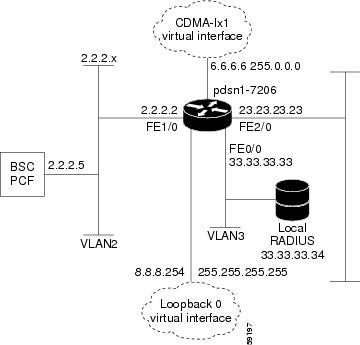
service cdma pdsn!hostname PDSN1-7206!aaa new-modelaaa authentication ppp default group radiusaaa authorization config-commandsaaa authorization network default group radiusaaa authorization configuration default group radiusaaa accounting update periodic 60aaa accounting network pdsn start-stop group radius!no ip gratuitous-arps!interface Loopback0ip address 8.8.8.254 255.255.255.255!interface CDMA-Ix1ip address 6.6.6.6 255.0.0.0!interface FastEthernet0/0! Interface for communication with RADIUS server and NMSip address 33.33.33.33 255.255.255.0!!!interface FastEthernet1/0! Interface to PCF - R-Pip address 2.2.2.2 255.255.255.0half-duplexno cdp enable!interface FastEthernet2/0! Interface to external network - Piip address 23.23.23.23 255.255.0.0!!!interface Virtual-Template1ip unnumbered Loopback0peer default ip address pool pdsn-poolppp accm 0ppp authentication chap pap optionalppp accounting noneppp timeout idle 2000!ip local pool pdsn-pool 8.8.8.1 8.8.8.253ip classles!!radius-server host 33.33.33.34 auth-port 1645 acct-port 1646 key ciscoradius-server retransmit 3radius-server vsa send authentication 3gpp2radius-server vsa send accounting 3gpp2cdma pdsn virtual-template 1cdma pdsn maximum sessions 16000cdma pdsn a10 max-lifetime 36000cdma pdsn msid-authenticationcdma pdsn secure pcf 2.2.2.5 spi 100 key ascii cisco!!!endCisco PDSN Configuration for Simple IP with VPDN
The configuration Simple IP with VPDN is identical to the configuration for Simple IP with two additional lines:
vpdn enablevpdn authen-before-forwardCisco PDSN Configuration for Mobile IP
Figure 10 and the information that follows is an example of PDSN architecture for Mobile IP service and its accompanying configuration. The example shows the configuration of PDSN1.
Figure 10 PDSN for Mobile IP—A Network Map
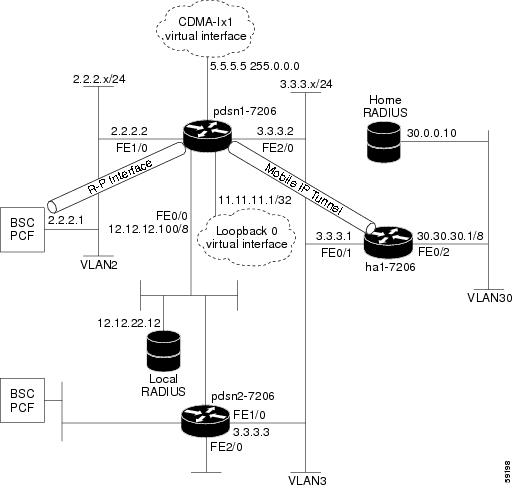
service cdma pdsn!hostname PDSN1-7206!aaa new-modelaaa authentication login default group radiusaaa authentication login CONSOLE noneaaa authentication ppp default group radiusaaa authorization config-commandsaaa authorization network default group radius!interface Loopback0ip address 11.11.11.1 255.255.255.255!interface CDMA-Ix1ip address 5.5.5.5 255.0.0.0!interface FastEthernet0/0description AAA NMS interfaceip address 12.12.12.100 255.0.0.0!interface FastEthernet1/0description R-P interfaceip address 2.2.2.2 255.255.255.0full-duplex!!interface FastEthernet2/0description Pi interfaceip address 3.3.3.2 255.255.255.0full-duplex!interface Virtual-Template1ip unnumbered loopback0ip mobile foreign-service challenge forward-mfce timeout 10 window 10ip mobile foreign-service reverse-tunnelno ip route-cacheno keepaliveppp authentication chap pap optionalppp timeout idle 2000!router mobile!ip classlessno ip http serverip mobile foreign-agent care-of FastEthernet2/0!radius-server host 12.12.22.12 auth-port 1645 acct-port 1646 key ascii ciscoradius-server retransmit 3radius-server vsa send authentication 3gpp2radius-server vsa send accounting 3gpp2cdma pdsn secure pcf 2.2.2.1 spi 100 key ascii ciscocdma pdsn virtual-template 1cdma pdsn msid-authentication!!endCombined Configuration for Cisco PDSN
The following example illustrates a PDSN configured for all scenarios: Simple IP, Simple IP with VPDN, Mobile IP, Proxy Mobile IP, and peer-to-peer PDSN selection.
service cdma pdsn!hostname PDSN1!aaa new-modelaaa authentication ppp default group radiusaaa authorization config-commandsaaa authorization network default group radiusaaa authorization configuration default group radiusaaa accounting update periodic 60aaa accounting network pdsn start-stop group radius!vpdn enablevpdn authen-before-forwardvirtual-profile aaausername HA password 0 rosebudusername LNS password 0 ciscousername PDSN password 0 ciscono ip gratuitous-arps!interface Loopback0ip address 8.8.8.254 255.255.255.255!interface CDMA-Ix1ip address 6.6.6.6 255.0.0.0!interface FastEthernet0/0! Interface for communication with RADIUS server and NMSip address 33.33.33.33 255.255.255.0!!!interface FastEthernet1/0! Interface to PCF - R-Pip address 2.2.2.2 255.255.255.0!interface FastEthernet2/0! Interface to external network - Piip address 23.23.23.23 255.255.0.0!!!interface Virtual-Template1ip unnumbered Loopback0ip mobile foreign-service challenge forward-mfce timeout 10 window 10ip mobile foreign-service reverse-tunnelno keepalivepeer default ip address pool pdsn-poolppp accm 0ppp authentication chap pap optionalppp accounting noneppp timeout idle 2000!router mobile!ip local pool pdsn-pool 8.8.8.1 8.8.8.253ip classlessip mobile foreign-agent care-of FastEthernet2/0!!radius-server host 33.33.33.34 auth-port 1645 acct-port 1646 key ciscoradius-server retransmit 3radius-server vsa send authentication 3gpp2radius-server vsa send accounting 3gpp2cdma pdsn virtual-template 1cdma pdsn maximum sessions 16000cdma pdsn a10 max-lifetime 36000cdma pdsn msid-authenticationcdma pdsn secure pcf 2.2.2.5 spi 100 key ascii ciscocdma pdsn secure cluster default spi 100 key ascii ciscocdma pdsn selection interface FastEthernet0/0!!!endPDSN Cluster Configuration
The following configuration illustrates 3 MWAMs in a 6500 configuration:
Verify hardware configuration on Cat6K:cat6500 router#sh moduleMod Ports Card Type----------------------------------------------1 2 Catalyst 6000 supervisor 2 (Active)3 48 SFM-capable 48-port 10/100 Mbps RJ454 2 IPSec VPN Accelerator5 16 SFM-capable 16 port 1000mb GBIC7 3 MWAM Module8 3 MWAM Module (MP)9 3 MWAM ModuleMod MAC addresses Hw Fw Sw Status--- ---------------------------------- ------ ------------ ------------ -------1 0005.7485.8494 to 0005.7485.8495 3.5 6.1(3) 6.2(2.108) Ok3 0001.63d7.2352 to 0001.63d7.2381 4.2 6.3(1) 6.2(2.108) Ok4 0008.7ca8.1386 to 0008.7ca8.1389 0.200 7.2(1) 6.2(2.108) Ok5 0001.63d6.cd92 to 0001.63d6.cda1 4.1 6.3(1) 6.2(2.108) Ok7 0001.0002.0003 to 0001.0002.000a 0.203 7.2(1) 1.0(0.1) Ok8 00e0.b0ff.3a10 to 00e0.b0ff.3a17 0.201 7.2(1) 1.2(0.12) ShutDown9 0002.0002.0003 to 0002.0002.000a 0.203 7.2(1) 1.0(0.1) OkMod Sub-Module Hw Status--- --------------------------- ------- -------1 Policy Feature Card 2 3.2 Ok1 Cat6k MSFC 2 daughterboard 2.2 Okcat6500 router#Controller configuration:cat6500 router#session slot 7 processor 6The default escape character is Ctrl-^, then x.You can also type 'exit' at the remote prompt to end the sessionTrying 127.0.0.76 ... OpenPress RETURN to get started!S76>S76>S76>S76>enS76#sh runS76#sh running-configBuilding configuration...Current configuration : 1489 bytes!! No configuration change since last restart!version 12.2service timestamps debug uptimeservice timestamps log uptimeno service password-encryptionservice cdma pdsn!hostname S76!!ip subnet-zeroip cef!!!interface Loopback1no ip address!interface GigabitEthernet0/0no ip address!interface GigabitEthernet0/0.401encapsulation dot1Q 401ip address 10.121.68.76 255.255.255.0standby 1 ip 10.121.68.98standby 1 priority 120standby 1 preemptstandby 1 name 6509-cluster!router mobile!ip classlessip route 10.10.72.1 255.255.255.255 10.121.68.72ip route 10.10.73.1 255.255.255.255 10.121.68.73ip route 10.10.74.1 255.255.255.255 10.121.68.74ip route 10.10.75.1 255.255.255.255 10.121.68.75ip route 10.10.92.1 255.255.255.255 10.121.68.92ip route 10.10.93.1 255.255.255.255 10.121.68.93ip route 10.10.94.1 255.255.255.255 10.121.68.94ip route 10.10.95.1 255.255.255.255 10.121.68.95ip route 128.0.0.0 255.255.255.0 GigabitEthernet0/1no ip http serverip pim bidir-enable!!!cdma pdsn secure pcf 10.121.68.62 10.121.68.66 spi 100 key ascii ciscocdma pdsn secure pcf 10.121.68.82 10.121.68.86 spi 100 key ascii ciscocdma pdsn secure cluster default spi 100 key ascii usercdma pdsn cluster controller interface GigabitEthernet0/0.401cdma pdsn cluster controller standby 6509-clustercdma pdsn cluster controller timeout 10cdma pdsn cluster controller window 3!line con 0line vty 0no loginline vty 1 4loginline vty 5 15login!endS76#cat6500 router#session slot 9 processor 6The default escape character is Ctrl-^, then x.You can also type 'exit' at the remote prompt to end the sessionTrying 127.0.0.96 ... OpenS96>Press RETURN to get started!S96>S96>S96>S96>enS96#sh runS96#sh running-configBuilding configuration...Current configuration : 1182 bytes!! No configuration change since last restart!version 12.2service timestamps debug uptimeservice timestamps log uptimeno service password-encryptionservice cdma pdsn!hostname S96!!ip subnet-zeroip cef!!!!interface Loopback1no ip address!interface CDMA-Ix1no ip address!interface GigabitEthernet0/0no ip address!interface GigabitEthernet0/0.401encapsulation dot1Q 401ip address 10.121.68.96 255.255.255.0standby 1 ip 10.121.68.98standby 1 priority 120standby 1 preemptstandby 1 name 6509-cluster!router mobile!ip classlessip route 10.10.72.1 255.255.255.255 10.121.68.72ip route 128.0.0.0 255.255.255.0 GigabitEthernet0/2no ip http serverip pim bidir-enable!!!cdma pdsn secure pcf 10.121.68.62 10.121.68.66 spi 100 key ascii ciscocdma pdsn secure pcf 10.121.68.82 10.121.68.86 spi 100 key ascii ciscocdma pdsn secure cluster default spi 100 key ascii usercdma pdsn cluster controller interface GigabitEthernet0/0.401cdma pdsn cluster controller standby 6509-clustercdma pdsn cluster controller timeout 10cdma pdsn cluster controller window 3!line con 0line vty 0no loginline vty 1 4loginline vty 5 15login!endS96#Verify active controller and standby controllerS76#sh standbyGigabitEthernet0/0.401 - Group 1State is Active2 state changes, last state change 00:27:09Virtual IP address is 10.121.68.98Active virtual MAC address is 0000.0c07.ac01Local virtual MAC address is 0000.0c07.ac01 (default)Hello time 3 sec, hold time 10 secNext hello sent in 2.112 secsPreemption enabled, min delay 0 sec, sync delay 0 secActive router is localStandby router is 10.121.68.96, priority 120 (expires in 9.064 sec)Priority 120 (configured 120)IP redundancy name is "6509-cluster"S76#S96#sh standbyGigabitEthernet0/0.401 - Group 1State is Standby1 state change, last state change 00:26:57Virtual IP address is 10.121.68.98Active virtual MAC address is 0000.0c07.ac01Local virtual MAC address is 0000.0c07.ac01 (default)Hello time 3 sec, hold time 10 secNext hello sent in 2.532 secsPreemption enabled, min delay 0 sec, sync delay 0 secActive router is 10.121.68.76, priority 120 (expires in 9.580 sec)Standby router is localPriority 120 (configured 120)IP redundancy name is "6509-cluster"S96#Members configuration:cat6500 router#session slot 7 processor 3The default escape character is Ctrl-^, then x.You can also type 'exit' at the remote prompt to end the sessionTrying 127.0.0.73 ... OpenS73>Press RETURN to get started!S73>S73>enS73#sh runS73#sh running-configBuilding configuration...Current configuration : 3192 bytes! Last configuration change at 04:10:06 UTC Sun Sep 15 2002!version 12.2service timestamps debug uptimeservice timestamps log uptimeno service password-encryptionservice cdma pdsn!hostname S73!aaa new-model!!aaa group server radius CSCO-30server 10.1.1.244 auth-port 1645 acct-port 1646server 10.1.1.200 auth-port 2812 acct-port 2813!aaa authentication ppp default local group radiusaaa authorization network default local group radiusaaa accounting network pdsn start-stop group radiusaaa session-id common!username root nopasswordusername cisco password 0 ciscousername pdsn password 0 ciscoip subnet-zeroip gratuitous-arpsip cef!!!interface Loopback1ip address 10.10.173.1 255.255.255.0!interface CDMA-Ix1ip address 10.10.73.1 255.255.255.0tunnel source 10.10.73.1tunnel key 16404tunnel sequence-datagrams!interface GigabitEthernet0/0no ip address!interface GigabitEthernet0/0.310encapsulation dot1Q 310ip address 10.1.1.73 255.255.255.0!interface GigabitEthernet0/0.401encapsulation dot1Q 401ip address 10.121.68.73 255.255.255.0!interface Virtual-Template1ip unnumbered Loopback1ip mobile foreign-service challenge forward-mfceip mobile foreign-service reverse-tunnelno keepalivepeer default ip address pool pdsn-poolppp accm 0ppp authentication chap pap optionalppp ipcp address uniquecdma pdsn mobile-advertisement-burst interval 500 number 3!router mobile!router ospf 100log-adjacency-changessummary-address 7.3.0.0 255.255.0.0redistribute connected subnets route-map MAP-DENYnetwork 10.10.73.1 0.0.0.0 area 73network 10.10.73.0 0.0.0.255 area 73network 10.10.173.1 0.0.0.0 area 0network 10.121.68.0 0.0.0.255 area 0!ip local pool pdsn-pool 7.3.1.0 7.3.16.255ip local pool pdsn-pool 7.3.17.0 7.3.32.255ip local pool pdsn-pool 7.3.33.0 7.3.48.255ip local pool pdsn-pool 7.3.49.0 7.3.64.255ip local pool pdsn-pool 7.3.65.0 7.3.78.255ip local pool pdsn-pool 7.3.79.0 7.3.79.31ip mobile foreign-agent care-of GigabitEthernet0/0.310ip classlessip route 128.0.0.0 255.255.255.0 GigabitEthernet0/1no ip http serverip pim bidir-enable!!access-list 9 deny 128.0.0.0 0.0.255.255access-list 9 permit any!route-map MAP-DENY permit 10match ip address 9set tag 9!radius-server host 10.1.1.244 auth-port 1645 acct-port 1646 key fooradius-server host 10.1.1.200 auth-port 2812 acct-port 2813 key fooradius-server retransmit 3radius-server deadtime 1radius-server vsa send accounting 3gpp2radius-server vsa send authentication 3gpp2cdma pdsn accounting local-timezonecdma pdsn virtual-template 1cdma pdsn send-agent-advcdma pdsn secure pcf 10.121.68.62 10.121.68.66 spi 100 key ascii ciscocdma pdsn secure pcf 10.121.68.82 10.121.68.86 spi 100 key ascii ciscocdma pdsn secure cluster default spi 100 key ascii usercdma pdsn cluster member controller 10.121.68.98cdma pdsn cluster member interface GigabitEthernet0/0.401cdma pdsn cluster member timeout 10cdma pdsn cluster member window 2!line con 0line vty 5 15!endS73#Show commands on ControllersS76#sh cdma pdsn cluster controller configurationcluster interface GigabitEthernet0/0.401no R-P signaling proxytimeout to seek member = 10 secondswindow to seek member is 3 timeouts in a row if no reply (afterwards the memberis declared offline)this PDSN cluster controller is configuredcontroller redundancy:database in-sync or no need to syncgroup: 6509-clusterS76#S76#sh cdma pdsn cluster controller member loadSecs until Seq seeks Member(past) seek no reply IPv4 Addr State Load--------------------------------------------------------3 0 10.10.95.1 ready 02 0 10.10.93.1 ready 08 0 10.10.92.1 ready 06 0 10.10.94.1 ready 05 0 10.10.72.1 ready 03 0 10.10.74.1 ready 09 0 10.10.75.1 ready 19 0 10.10.73.1 ready 3--------------------------------------------------------Controller IPv4 Addr 10.121.68.98S76#S76#sh cdma pdsn cluster controller member 10.10.73.1PDSN cluster member 10.10.73.1 state readyregistered with PDSN controller 10.121.68.98reported load 7 percent, will be sought in 9 secondsmember statistics collected in the controller:14 CVSEs seek reply received9 CVSEs seek received0 state changed to admin prohibited0 state changed to ready0 seek A11-RegReq sent in a row, no reply21171 A10 up A11-RegReq received23387 A10 end A11-RegReq receivedS76#S76#sh cdma pdsn cluster controller statistics0 times did not get a buffer for a packet0 times couldn't allocate memory836 A11-RegReply received0 A11-RegReply discarded, authenticaton problem0 A11-RegReply discarded, identification problem0 A11-RegReply discarded, unrecognized extension68818 A11-RegRequest received0 A11-RegRequest discarded, authenticaton problem1714 A11-RegRequest discarded, identification problem0 A11-RegRequest discarded, unrecognized application type0 A11-RegRequest discarded, unrecognized extension0 A11-RegRequest with unrecognized type of data0 A11-RegRequest not sent, interface cdma-Ix not configed836 CVSEs seek reply received775 CVSEs seek received0 CVSEs state ready received0 CVSEs state admin prohibited received0 msgs received neither A11-RegReq nor A11-RegReply31898 A10 up A11-RegReq received34434 A10 end A11-RegReq received8 PDSN cluster membersredundancy:error: mismatch id 5 authen fail 0ignore due to no redundancy 0Update rcvd 0 sent 68437 orig sent 67600 fail 221UpdateAck rcvd 68411 sent 0DownloadReq rcvd 6 sent 0 orig sent 0 fail 0DownloadReply rcvd 0 sent 13 orig sent 13 fail 0 drop 0DownloadAck rcvd 13 sent 0 drop 0S76#S76#sh cdma pdsn cluster controller session ?count Count of session recordsimsi Session record for International Mobile Subscriber Identityoldest Oldest session recordS76#sh cdma pdsn cluster controller session olS76#sh cdma pdsn cluster controller session oldest ?more The oldest and a few more session records to show| Output modifiers<cr>S76#sh cdma pdsn cluster controller session oldestIMSI Member IPv4 Addr Age [days] Anchor changes----------------------------------------------------------------62000015434 10.10.73.1----------------------------------------------------------------S76#sh cdma pdsn cluster controller session imsi 62000015434IMSI Member IPv4 Addr Age [days] Anchor changes----------------------------------------------------------------62000015434 10.10.73.1----------------------------------------------------------------S76#Show commands on member:S73#sh cdma pdsn cluster member configurationcluster interface GigabitEthernet0/0.401IP address of controller is 10.121.68.98no prohibit administrativelytimeout to resend status or seek controller = 10 sec or less, randomizedresend a msg for 2 timeouts sequentially if no reply, then inform operatorthis PDSN cluster member is configuredS73#S73#sh cdma pdsn cluster member statistics0 times did not get a buffer for a packet0 times couldn't allocate memory48804 A11-RegReply received0 A11-RegReply discarded, authenticaton problem0 A11-RegReply discarded, identification problem0 A11-RegReply discarded, unrecognized extension15 A11-RegRequest received0 A11-RegRequest discarded, authenticaton problem0 A11-RegRequest discarded, identification problem0 A11-RegRequest discarded, unrecognized application type0 A11-RegRequest discarded, unrecognized extension0 A11-RegRequest with unrecognized type of data0 A11-RegRequest not sent, interface cdma-Ix not configed15 seek A11-RegReq received9 CVSEs seek reply received0 CVSEs state reply received0 msgs received neither A11-RegReq nor A11-RegReply24412 A10 up A11-RegReply received24405 A10 end A11-RegReply received0 CVSEs seek in sequence without a msg from controller0 CVSEs state in sequence without a reply from controllercontroller aliveS73#Cat6k SUP configurationcat6500 router#sh running-configBuilding configuration...Current configuration : 9838 bytes!! Last configuration change at 00:21:56 UTC Sat Sep 14 2002 by root! NVRAM config last updated at 14:10:00 UTC Fri Sep 13 2002 by root!version 12.2service timestamps debug uptimeservice timestamps log datetime localtimeno service password-encryption!hostname cat6500 router!boot system slot0:c6sp222-jk9sv-mzboot device module 4 cf:3boot device module 5 cf:4boot device module 6 cf:4boot device module 7 cf:4boot device module 8 cf:4boot device module 9 cf:4aaa new-modelaaa authentication login default localaaa authorization exec default localenable secret level 1 5 $1$T17C$7icHsiM4vHj6nIE6medGj.enable secret level 6 5 $1$wB/9$.ML91zZopFpYp12VNxA1p.enable password lab!username u0 privilege 0 password 0 ciscousername root nopasswordusername u1 password 0 ciscousername u6 privilege 6 password 0 ciscousername u8 privilege 8 password 0 ciscousername cisco password 0 ciscousername u2 privilege 2 nopasswordusername u15 privilege 15 nopasswordusername u10 privilege 10 nopasswordusername v1 nopassword user-maxlinks 1!monitor session 1 source interface Fa3/24monitor session 1 destination interface Fa3/12redundancymain-cpuauto-sync standardip subnet-zero!!no ip domain-lookup!mls flow ip destinationmls flow ipx destination!!no spanning-tree vlan 310!!!interface Loopback1ip address 10.10.10.10 255.255.255.0!interface Port-channel1no ip addresssnmp trap link-statusswitchportswitchport access vlan 401!interface GigabitEthernet1/1no ip addresssnmp trap link-statusswitchportswitchport access vlan 309switchport mode access!interface GigabitEthernet1/2no ip addresssnmp trap link-statusswitchportswitchport access vlan 401switchport mode access!interface GigabitEthernet2/1no ip addresssnmp trap link-statusswitchportswitchport access vlan 310switchport mode access!interface GigabitEthernet2/2no ip addressshutdown!interface FastEthernet3/1no ip addresssnmp trap link-statusswitchportswitchport access vlan 222!interface FastEthernet3/2no ip addressshutdown!interface FastEthernet3/3no ip addressshutdown!interface FastEthernet3/4no ip addressshutdown!interface FastEthernet3/5no ip addresssnmp trap link-statusswitchportswitchport access vlan 66switchport mode access!interface FastEthernet3/6no ip addresssnmp trap link-statusswitchportswitchport access vlan 66switchport mode access!interface FastEthernet3/7no ip addresssnmp trap link-statusswitchportswitchport access vlan 66switchport mode access!interface FastEthernet3/8ip address 1.1.1.1 255.255.255.0shutdown!interface FastEthernet3/9no ip addressshutdown!interface FastEthernet3/10no ip addresssnmp trap link-statusswitchportswitchport access vlan 401channel-group 1 mode on!interface FastEthernet3/11no ip addresssnmp trap link-statusswitchportswitchport access vlan 401channel-group 1 mode on!interface FastEthernet3/12no ip addresssnmp trap link-statusswitchportswitchport access vlan 401!interface FastEthernet3/13no ip addresssnmp trap link-statusswitchportswitchport access vlan 401!interface FastEthernet3/14no ip addressshutdown!interface FastEthernet3/15ip address 3.3.3.3 255.255.255.0shutdown!interface FastEthernet3/16no ip addressshutdown!interface FastEthernet3/17no ip addresssnmp trap link-statusswitchportswitchport access vlan 311switchport mode access!interface FastEthernet3/18no ip addressshutdown!interface FastEthernet3/19no ip addressshutdown!interface FastEthernet3/20no ip addressshutdown!interface FastEthernet3/21no ip addresssnmp trap link-statusswitchportswitchport access vlan 401!interface FastEthernet3/22no ip addresssnmp trap link-statusswitchportswitchport access vlan 401!interface FastEthernet3/23no ip addresssnmp trap link-statusswitchportswitchport access vlan 401!interface FastEthernet3/24no ip addresssnmp trap link-statusswitchportswitchport access vlan 401!interface FastEthernet3/25no ip addresssnmp trap link-statusswitchportswitchport access vlan 401!interface FastEthernet3/26no ip addresssnmp trap link-statusswitchportswitchport access vlan 401!interface FastEthernet3/27no ip addressshutdown!interface FastEthernet3/28no ip addressshutdown!interface FastEthernet3/29no ip addressshutdown!interface FastEthernet3/30no ip addresssnmp trap link-statusswitchportswitchport access vlan 310!interface FastEthernet3/31no ip addresssnmp trap link-statusswitchportswitchport access vlan 310!interface FastEthernet3/32no ip addresssnmp trap link-statusswitchportswitchport access vlan 310!interface FastEthernet3/33no ip addresssnmp trap link-statusswitchportswitchport access vlan 310!interface FastEthernet3/34no ip addresssnmp trap link-statusswitchportswitchport access vlan 310!interface FastEthernet3/35no ip addresssnmp trap link-statusswitchportswitchport access vlan 310!interface FastEthernet3/36no ip addresssnmp trap link-statusswitchportswitchport access vlan 310!interface FastEthernet3/37no ip addresssnmp trap link-statusswitchportswitchport access vlan 310!interface FastEthernet3/38no ip addresssnmp trap link-statusswitchportswitchport access vlan 310!interface FastEthernet3/39no ip addresssnmp trap link-statusswitchportswitchport access vlan 310!interface FastEthernet3/40no ip addressshutdownsnmp trap link-statusswitchportswitchport access vlan 333!interface FastEthernet3/41no ip addresssnmp trap link-statusswitchportswitchport access vlan 310!interface FastEthernet3/42no ip addresssnmp trap link-statusswitchportswitchport access vlan 310!interface FastEthernet3/43no ip addresssnmp trap link-statusswitchportswitchport access vlan 310!interface FastEthernet3/44no ip addresssnmp trap link-statusswitchportswitchport access vlan 310!interface FastEthernet3/45no ip addresssnmp trap link-statusswitchportswitchport access vlan 310!interface FastEthernet3/46no ip addresssnmp trap link-statusswitchportswitchport access vlan 310!interface FastEthernet3/47no ip addresssnmp trap link-statusswitchportswitchport access vlan 333!interface FastEthernet3/48no ip addresssnmp trap link-statusswitchportswitchport access vlan 333!interface GigabitEthernet4/1no ip addresssnmp trap link-statusswitchportswitchport trunk encapsulation dot1qswitchport trunk allowed vlan 1,1002-1005switchport mode trunkflowcontrol receive oncdp enable!interface GigabitEthernet4/2no ip addresssnmp trap link-statusswitchportswitchport trunk encapsulation dot1qswitchport trunk allowed vlan 1,1002-1005switchport mode trunkflowcontrol receive oncdp enable!interface GigabitEthernet5/1no ip addressshutdown!interface GigabitEthernet5/2no ip addressshutdown!interface GigabitEthernet5/3no ip addressshutdown!interface GigabitEthernet5/4no ip addressshutdown!interface GigabitEthernet5/5no ip addressshutdown!interface GigabitEthernet5/6no ip addressshutdown!interface GigabitEthernet5/7no ip addressshutdown!interface GigabitEthernet5/8no ip addressshutdown!interface GigabitEthernet5/9no ip addressshutdown!interface GigabitEthernet5/10no ip addressshutdown!interface GigabitEthernet5/11no ip addressshutdown!interface GigabitEthernet5/12no ip addressshutdown!interface GigabitEthernet5/13no ip addressshutdown!interface GigabitEthernet5/14no ip addressshutdown!interface GigabitEthernet5/15no ip addressshutdown!interface GigabitEthernet5/16no ip addressshutdown!interface Vlan1no ip addressshutdown!interface Vlan222ip address 172.19.23.16 255.255.254.0ip nat outside!interface Vlan309no ip address!interface Vlan310ip address 10.1.1.222 255.255.255.0ip nat inside!interface Vlan401ip address 10.121.68.200 255.255.255.0!router ospf 100log-adjacency-changesnetwork 10.10.10.10 0.0.0.0 area 0network 10.121.68.0 0.0.0.255 area 0default-information originate!ip nat inside source list 100 interface Vlan222 overloadip classlessip route 0.0.0.0 0.0.0.0 172.19.26.1ip route 0.0.0.0 0.0.0.0 172.19.22.1ip route 5.5.5.0 255.255.255.0 10.1.1.92ip route 10.10.113.1 255.255.255.255 10.1.1.221ip route 10.10.116.1 255.255.255.255 10.1.1.221ip route 10.10.195.1 255.255.255.255 10.1.1.95no ip http serverip pim bidir-enable!!ip access-list extended VRZ-101permit ip host 10.10.195.1 host 10.10.116.1access-list 100 permit ip 5.0.0.0 0.255.255.255 anyarp 127.0.0.22 0000.2200.0000 ARPAarp 127.0.0.12 0000.2100.0000 ARPA!route-map MAP deny 10match ip address 100!snmp-server community public ROsnmp-server community private RWsnmp-server enable traps casasnmp-server enable traps vtpsnmp-server enable traps hsrpsnmp-server enable traps configsnmp-server enable traps entitysnmp-server enable traps bgpsnmp-server enable traps rsvpsnmp-server enable traps frame-relaysnmp-server enable traps syslogsnmp-server enable traps rtrsnmp-server enable traps dlswsnmp-server enable traps isdn call-informationsnmp-server enable traps isdn layer2snmp-server host 10.1.1.199 public!privilege configure level 8 snmp-server communityprivilege configure level 8 usernameprivilege configure level 8 username u10 privilege 10 nopasswordprivilege exec level 6 show runningprivilege exec level 8 config terminal!line con 0exec-timeout 0 0line vty 0 4exec-timeout 0 0password labtransport input lat pad mop telnet rlogin udptn nasiline vty 5 10exec-timeout 0 0!ntp master 3endPDSN Accounting
The following RADIUS attributes are contained in the UDR sent by PDSN.
The following list identifies the prepaid VSAs that can be included in the RADIUS attributes contained in the Accounting Stop Record:
•
•
•
•
•
•
•
•
•
AAA Authentication and Authorization Profile
This section describes User Profiles to be configured at the AAA server for authentication and authorization of users for various service types (Simple IP, Mobile IP, etc.). It also describes the minimal configuration required for the same.
1.
The client profile contains the ip address of the router and the shared key. The following example illustrates a client profile:
[ //localhost/Radius/Clients/username ]Name = usernameDescription =IPAddress = 9.15.68.7SharedSecret = labType = NASVendor =IncomingScript~ =OutgoingScript~ =UseDNIS = FALSEDeviceName =DevicePassword =2.
A user profile contains username, password, and the base profile where attributes retrieved during authorization can be configured.
The following example illustrates a user profile:
[ //localhost/Radius/UserLists/Default/username ]Name = usernameDescription =Password = <encrypted>AllowNullPassword = FALSEEnabled = TRUEGroup~ =BaseProfile~ = username-sipAuthenticationScript~ =AuthorizationScript~ =UserDefined1 =3.
The following example illustrates a base profile :
[ //localhost/Radius/Profiles/username-sip ]Name = username-sipDescription =Attributes/4.
[ //localhost/Radius/Profiles/username-sip/Attributes ]cisco-avpair = lcp:cdma-user-class=1AAA Profiles for Various Service Types
The following examples document AAA profiles for various service types such as SIP, MoIP, and others. The mandatory/optional attributes, and the attributes required to be configured for enabling different features, are specified.
Simple IP
cisco-avpair = lcp:cdma-user-class=1
The following attributes are optional and are needed only for specific scenarios :
•
Framed-IP-Address = 8.1.0.2
•
cisco-avpair = ip:addr-pool=pdsn-pool
•
cisco-avpair = "lcp:interface-config=compress stac"
cisco-avpair = "lcp:interface-config=compress mppc"
cisco-avpair = "lcp:interface-config=compress predictor"
•
Framed-Protocol = PPP
Framed-Routing = None
Service-Type = Framed
VPDN
cisco-avpair = vpdn:tunnel-type=l2tp
cisco-avpair = vpdn:ip-addresses=5.5.5.1
cisco-avpair = vpdn:l2tp-tunnel-password=cisco
The following configuration is optional at AAA contacted by LNS :
cisco-avpair = ip:addr-pool=pdsn-pool
MSID based Authentication
•
cisco-avpair = cdma:cdma-realm=cisco.com
cisco-avpair = lcp:cdma-user-class=1
•
cisco-avpair = lcp:cdma-user-class=3
cisco-avpair = cdma:cdma-realm=cisco.com
cisco-avpair = "lcp:spi#0 = spi 100 key ascii cisco"
cisco-avpair = lcp:cdma-ha-ip-addr=5.5.5.1
Proxy Mobile IP
cisco-avpair = lcp:cdma-ha-ip-addr=5.5.5.1
cisco-avpair = "lcp:spi#0 = spi 100 key ascii cisco"
cisco-avpair = lcp:cdma-user-class=3
Mobile IP
•
The following attributes are optional, and are only needed for specific scenarios:
–
CDMA-HA-IP-Addr = 6.0.0.2
–
cisco-avpair = "mobileip:spi#0=spi 100 key ascii cisco"
cisco-avpair = "mobileip:static-ip-addresses=20.0.0.1 20.0.0.2 20.0.0.3 20.0.0.4"
–
cisco-avpair = "mobileip:spi#0=spi 100 key ascii cisco"
cisco-avpair = "mobileip:static-ip-pool=mypool"
Prepaid (Optional)
•
Command Reference
This section lists new and revised commands pertaining to the PDSN software. All other commands used with this feature are documented in the Cisco IOS Release 12.2 command reference publications.
•
•
•
•
•
•
•
•
•
•
•
•
•
•
•
•
•
•
•
•
•
•
•
•
•
•
•
•
•
•
•
access list
To configure the access list mechanism for filtering frames by protocol type or vendor code, use the access-list global configuration command. Use the no form of this command to remove the single specified entry from the access list.
access-list access-list-number {permit | deny} {type-code wild-mask | address mask}
no access-list access-list-number {permit | deny} {type-code wild-mask | address mask}
Syntax Description
Defaults
No numbered encryption access lists are defined, and therefore no traffic will be encrypted/decrypted. After being defined, all encryption access lists contain an implicit "deny" ("do not encrypt/decrypt") statement at the end of the list..
Command Modes
Global configuration
Command History
Usage Guidelines
Use encryption access lists to control which packets on an interface are encrypted/decrypted, and which are transmitted as plain text (unencrypted).
When a packet is examined for an encryption access list match, encryption access list statements are checked in the order that the statements were created. After a packet matches the conditions in a statement, no more statements will be checked. This means that you need to carefully consider the order in which you enter the statements.
To use the encryption access list, you must first specify the access list in a crypto map and then apply the crypto map to an interface, using the crypto map (CET global configuration) and crypto map (CET interface configuration) commands.
Fragmented IP packets, other than the initial fragment, are immediately accepted by any extended IP access list. Extended access lists used to control virtual terminal line access or restrict contents of routing updates must not match the TCP source port, the type of service value, or the packet's precedence.
Note

Caution
Note
Examples
The following example creates a numbered encryption access list that specifies a class C subnet for the source and a class C subnet for the destination of IP packets. When the router uses this encryption access list, all TCP traffic that is exchanged between the source and destination subnets will be encrypted.
access-list 101 permit tcp 172.21.3.0 0.0.0.255 172.22.2.0 0.0.0.255cdma pdsn a10 ahdlc engine
To limit the number of AHDLC channel resources provided by the AHDLC engine, use the cdma pdsn a10 ahdlc engine command to in global configuration mode. To reset the number of AHDLC channel resources to the default, use the no form of this command.
cdma pdsn a10 ahdlc engine slot usable-channels usable-channels
no cdma pdsn a10 ahdlc engine slot usable-channels
Syntax Description
Defaults
The default number of usable channels equals the maximum channels supported by the engine; the c-5 images supports 8000 sessions, and all c-6 image support 20000 sessions.
Command Modes
Global configuration
Command History
12.2(2)XC
This command was introduced.
12.2(8)BY
The maximum number of usable channels was increased to 20000.
Usage Guidelines
If the value of usable-channels is greater than default maximum channels provided by the engine, the command will fail.
If the engine has any active channels, the command will fail.
Examples
The following example limits the number of service channels provided by the AHDLC engine to 1000:
cdma pdsn a10 ahdlc engine 0 usable-channels 1000Related Commands
cdma pdsn a10 gre sequencing
To enable inclusion of GRE sequence numbers in the packets sent over the A10 interface, use the cdma pdsn gre sequencing command in global configuration mode. To disable the inclusion of GRE sequence number in the packets sent over the A10 interface, use the no form of this command.
cdma pdsn a10 gre sequencing
no cdma pdsn a10 gre sequencing
Syntax Description
This command has no arguments or keywords.
Defaults
GRE sequence numbers are included in the packets sent over the A10 interface.
Command Modes
Global configuration
Command History
Examples
The following example instructs Cisco PDSN to include per-session GRE sequence numbers in the packets sent over the A10 interface:
cdma pdsn a10 gre sequencingRelated Commands
cdma pdsn a10 max-lifetime
To specify the maximum A10 registration lifetime accepted, use the cdma pdsn a10 max-lifetime command in global configuration mode. To return to the default length of time, use the no form of this command.
cdma pdsn a10 max-lifetime seconds
no cdma pdsn a10 max-lifetime
Syntax Description
seconds
Maximum A10 registration lifetime accepted by Cisco PDSN. The range is 1 to 65535 seconds. The default is 1800 seconds.
Defaults
1800 seconds.
Command Modes
Global configuration
Command History
Examples
The following example specifies that the A10 interface will be maintained for 1440 seconds:
cdma pdsn a10 max-lifetime 1440Related Commands
cdma pdsn a11 dormant ppp-idle-timeout send-termreq
To specify that for dormant sessions, on ppp idle timeout, ppp termreq will be sent, use the cdma pdsn all dormant ppp-idle-timeout send-termreq command in global configuration mode. To disble this feature, use the no form of this command.
cdma pdsn all dormant ppp-idle-timeout send-termreq
no cdma pdsn all dormant ppp-idle-timeout send-termreq
Syntax Description
There are no keywords or variable for this command.
Defaults
There are no default values.
Command Modes
Global configuration
Command History
Usage Guidelines
Disabling this behaviour will avoid traffic channel allocation for cleaning up ppp sessions at the mobile.
Examples
router# cdma pdsn a11 dormant ppp-idle-timeout send-termreq
cdma pdsn accounting local-timezone
To specify the local time stamp for PDSN accounting events, use the cdma pdsn accounting local-timezone command in global configuration mode. To return to the default Universal Time (UTC), use the no form of this command.
cdma pdsn accounting local-timezone
no cdma pdsn accounting local-timezone
Syntax Description
This command has no arguments or keywords.
Defaults
UTC time, a standard based on GMT, is enabled.
Command Modes
Global configuration
Command History
Usage Guidelines
You must use the clock timezone hours-offset [minutes-offset] global configuration command to reflect the difference between local time and UTC time.
Examples
The following example sets the local time in Korea:
clock timezone KOREA 9cdma pdsn accounting local-timezoneRelated Commands
cdma pdsn accounting send cdma-ip-tech
To configure specific values for the F11 attribute for proxy Mobile IP and VPDN services, use the cdma pdsn accounting send cdma-ip-tech command in global configuration mode. To deconfigure those values, use the no form of this command.
cdma pdsn accounting send cdma-ip-tech [proxy-mobile-ip | vpdn]
no cdma pdsn accounting send cdma-ip-tech [proxy-mobile-ip | vpdn]
Syntax Description
proxy-mobile-ip
Sets the IP-Tech proxy-mobile-ip number. Values are 3-65535.
vpdn
Sets the IP-Tech vpdn number. Values are 3-65535.
Defaults
No default behavior or values.
Command Modes
Global configuration.
Command History
Examples
pdsn(config)#cdma pdsn accounting send cdma-ip-tech proxy-mobile-ip 3pdsn(config)#cdma pdsn accounting send cdma-ip-tech vpdn 4cdma pdsn accounting send start-stop
To cause the PDSN to send accounting records when the call transitions between active and dormant states, use the cdma pdsn accounting send start-stop command in global configuration mode. To stop sending accounting records, use the no form of this command.
cdma pdsn accounting send {start-stop | cdma-ip-tech}
no cdma pdsn accounting send {start-stop | cdma-ip-tech}
Syntax Description
start-stop
Informs the PDSN when to begin sending accounting records and when to stop sending them.
cdma-ip-tech
Accounting records are generated with special IP-Tech number.
Defaults
No default behavior or values.
Command Modes
Global configuration
Command History
Usage Guidelines
When this feature is enabled, the PDSN will send:
•
•
Examples
The following example starts sending PDSN accounting events:
cdma pdsn accounting send start-stopRelated Commands
cdma pdsn accounting time-of-day
To set the accounting information for specified times during the day, use the cdma pdsn accounting time-of-day command in global configuration mode. To disable the specification, use the no form of this command.
cdma pdsn accounting time-of-day hh:mm:ss
no cdma pdsn accounting time-of-day
Syntax Description
Defaults
No default behavior or values.
Command Modes
Global configuration
Command History
Usage Guidelines
This command is used to facilitate billing when a user is charged different prices based upon the time of the day. Up to ten different accounting triggers can be configured.
Examples
The following example sets an accounting trigger for 13:30:20:
cdma pdsn accounting time-of-day 13:30:30Related Commands
cdma pdsn age-idle-users
To configure the aging of idle users, use the cdma pdsn age-idle-users command. To stop aging out idle users, use the no form of this command.
cdma pdsn age-idle-users [minimum-age value]
no cdma pdsn age-idle-users
Syntax Description
minimum-age value
(Optional) The minimum number of seconds a user should be idle before they are a candidate for being aged out. Possible values are 1 through 65535.
Defaults
By default, no idle users are aged out.
Command Modes
Global configuration
Command History
Usage Guidelines
If no value is specified, the user that has been idle the longest will be aged out. If an age is specified and the user that has been idle the longest has not been idle for the specified value, then no users are aged out.
Examples
The following example sets a minimum age out value of 5 seconds:
cdma pdsn age-idle-users minimum-age 5cdma pdsn cluster controller
To configure the PDSN to operate as a cluster controller, and to configure various parameters on the cluster controller, use the cdma pdsn cluster controller command. To disable certain cluster controller parameters, use the no form of this command.
cdma pdsn cluster controller [ interface interface-name | timeout seconds [window number] | window number ]
no cdma pdsn cluster controller [ interface interface-name | timeout seconds [window number] | window number ]
Syntax Description
Defaults
The timeout default value is 300 seconds.
Command Modes
Global configuration
Command History
Examples
The following example enables the cdma cluster controller:
cdma pdsn cluster controller interface FastEthernet1/0cdma pdsn cluster member
To configure the PDSN to operate as a cluster member, and to configure various parameters on the cluster member, use the cdma pdsn cluster member command. To disable certain cluster controller parameters, use the no form of this command.
cdma pdsn cluster member [ controller ipaddr | interface interface-name | prohibit type | timeout seconds [window number] | window number ]
no cdma pdsn cluster member [ controller ipadd | interface interface-name | timeout seconds [window number] | window number ]
Syntax Description
Defaults
The default timeout value for the cluster member is 300 seconds.
Command Modes
Global configuration
Command History
Usage Guidelines
The prohibit field enables a member to administratively rid itself of its load without service interruption. When enabled, the member is no longer given any new data sessions by the controller.
Examples
The following example enables a cdma pdsn cluster member:
cdma pdsn cluster member interface FastEthernet1/0cdma pdsn compliance iosv4.1 session-reference
3GPP2 IOS version 4.2 mandates that the Session Reference ID in the A11 Registration Request is always set to 1. To configure the PDSN to interoperate with a PCF that is not compliant with 3GPP2 IOS version 4.2, use the cdma pdsn compliance iosv4.1 session-reference command inGlobal configuration mode. To disable this configuration, use the no form of this command.
cdma pdsn compliance iosv4.1 session-reference
no cdma pdsn compliance iosv4.1 session-reference
Syntax Description
This command has no arguments or keywords.
Defaults
Session Reference ID set to 1 in the A11 registration Request is on by default.
Command Modes
Global configuration.
Command History
Examples
The following command instructs the PDSN to skip any checks done on the session reference id of incoming Registration Requests to ensure that they are set to 1.
router # cdma pdsn compliance iosv4.1 session-referenceRelated Commands
debug cdma pdsn a11
Displays debug messages for A11 interface errors, events, and packets.
cdma pdsn compliance is835a esn-optional
To send an ESN value in accounting packets to the RADIUS server only if it has received an ESN value (A2) in the A11 RRQ from PCF, use the cdma pdsn compliance is835 esn-optional command in global configuration mode. To disable the specification, use the no form of this command.
cdma pdsn compliance is835 esn-optional
no cdma pdsn compliance is835 esn-optional
Syntax Description
There are no keywords or arguments for this command.
Defaults
The default behavior is to send the ESN attribute in all accounting records..
Command Modes
Global configuration
Command History
Usage Guidelines
If no A2 is received in the RRQ, the PDSN will not send the ESN attribute in the accounting record. This behavior is in accordance to IS835A.
If this command is not confogired, the PDSN will send the ESN value regardless whether the A2 attribute value is received from PCF or not. This is in accordance to IS835B.
cdma pdsn failure-history
To configure CDMA PDSN SNMP session failure history size, use the cdma pdsn failure-history command in global configuration mode. To return to the default length of time, use the no form of this command.
cdma pdsn failure-history entries
no cdma pdsn failure-history
Syntax Description
entries
Maximum number of entries that can be recorded in the SNMP session failure table. Possible values are 0 through 2000.
Defaults
No default behavior or values.
Command Modes
Global configuration
Command History
Examples
The following example specifies that 1000 is the maximum number of entries that can be recorded in the SNMP session table:
cdma pdsn failure-history 1000Related Commands
cdma pdsn ingress-address-filtering
To enable ingress address filtering, use the cdma pdsn ingress-address-filtering command in global configuration mode. To disable ingress address filtering, use the no form of this command.
cdma pdsn ingress-address-filtering
no cdma pdsn ingress-address-filtering
Syntax Description
This command has no arguments or keywords.
Defaults
Ingress address filtering is disabled.
Command Modes
Global configuration
Command History
Usage Guidelines
When this command is configured, the PDSN checks the source IP address of every packet received on the PPP link from the mobile station. If the address is not associated with the PPP link to the mobile station and is not an MIP RRQ or Agent Solicitation, then the PDSN discards the packet and sends a request to reestablish the PPP link.
Examples
The following example enables ingress address filtering:
cdma pdsn ingress-address-filteringRelated Commands
show cdma pdsn
Displays the current status and configuration of the PDSN gateway.
show cdma pdsn session
Displays the session information on the PDSN.
cdma pdsn maximum pcf
To set the maximum number of PCFs that can connect to a PDSN, use the cdma pdsn maximum pcf command in global configuration mode. To disable a configured limit, use the no form of this command.
cdma pdsn maximum pcf maxpcf
no cdma pdsn maximum pcf
Syntax Description
Defaults
No default behavior or values.
Command Modes
Global Configuration
Command History
Usage Guidelines
If no maximum number of PCFs is configured, the only limitation is the amount of memory.
You can configure the maximum PCFs to be less than the existing PCFs. As a result, when you issue the show cdma pdsn command, you may see more existing PCFs than the configured maximum. It is the responsibility of the user to bring down the existing PCFs to match the configured maximum.
Examples
The following example specifies that 200 PCFs can be sent:
cdma pdsn maximum pcf 200Related Commands
show cdma pdsn
Displays the current status and configuration of the PDSN gateway.
cdma pdsn maximum sessions
To set the maximum number of mobile sessions allowed on a PDSN, use the cdma pdsn maximum sessions command in global configuration mode. To disable a configured limit, use the no form of this command.
cdma pdsn maximum sessions maxsessions
no cdma pdsn maximum sessions
Syntax Description
maxsessions
Maximum number of mobile sessions allowed on a PDSN. Possible values depend on which image you are using.
Defaults
The c-5 images support 8000 sessions, and the c-6 images support 20000 sessions.
Command Modes
Global Configuration.
Command History
12.1(3)XS
This command was introduced.
12.2(8)BY
The maximum number of mobile sessions was raised to 20000.
Usage Guidelines
If PDSN runs out of resources before the configured number is reached, then PDSN will reject the creation of further sessions.
You can configure the maximum sessions to be less than the existing sessions. As a result, when you issue the show cdma pdsn command, you may see more existing sessions than the configured maximum. It is the responsibility of the user to bring down the existing sessions to match the configured maximum.
Examples
The following example sets the maximum number of mobile sessions to 100:
cdma pdsn maximum sessions 100Related Commands
cdma pdsn mobile-advertisement-burst
To configure the number and interval of Agent Advertisements that a PDSN FA can send, use the cdma pdsn mobile-advertisement-burst command in interface configuration mode. To reset the configuration to the defaults, use the no form of this command.
cdma pdsn mobile-advertisement-burst {number value | interval msec}
no cdma pdsn mobile-advertisement-burst {number | interval}
Syntax Description
Defaults
The default number of agent advertisements to send is 5.
The default interval between advertisements is 200 milliseconds.
Command Modes
Interface Configuration.
Command History
Usage Guidelines
You must specify at least one of the optional parameters. Otherwise, the command has no effect. When virtual-access interfaces are created from the virtual template, default values will be used for any parameters not already configured on the virtual template.
This command should be configured on virtual templates only, and only when PDSN service is configured.
Examples
The following example configures PDSN FA advertisement:
cdma pdsn mobile-advertisement-burst number 10 interval 500Related Commands
cdma pdsn msid-authentication
To enable MSID-based authentication and access, use the cdma pdsn msid-authentication command in global configuration mode. To disable MSID-based authentication and access, use the no form of this command.
cdma pdsn msid-authentication [imsi number] [irm number] [min number] [profile-password password]
no cdma pdsn msid-authentication
Syntax Description
Defaults
MSID authentication is disabled. When enabled, the default values are as follows:
•
•
•
•
Command Modes
Global Configuration.
Command History
12.1(3)XS
This command was introduced.
12.2(2)XC
The profile-password keyword was added.
Usage Guidelines
MSID authentication provides Simple IP service for mobile stations that do not negotiate CHAP or PAP. Cisco PDSN retrieves a network profile based on the MSID from the RADIUS server. The network profile should include the internet realm of the home network that owns the MSID. Cisco PDSN constructs the NAI from the MSID and the realm. The constructed NAI is used in generated accounting records. If the PDSN is unable to obtain the realm, then it denies service to the mobile station.
The identifier used to retrieve the network profile from the RADIUS server depends on the format of the MSID, which can be one of the following:
•
•
•
If the mobile station uses IMSI, the default identifier that PDSN uses to retrieve network profile is of the form IMSI-nnnnn where nnnnn is the first five digits of the IMSI. The number of digits from the IMSI to be used can be configured using the command cdma pdsn msid-authentication imsi.
If the mobile station uses MIN, the default identifier that PDSN uses to retrieve network profile is of the form MIN-nnnnnn where nnnnnn is the first six digits of the MIN. The number of digits from the MIN to be used can be configured using the command cdma pdsn msid-authentication min.
If the mobile station uses IRM, the default identifier that PDSN uses to retrieve network profile is of the form IRM-nnnn where nnnn is the first four digits of the IRM. The number of digits from the IRM to be used can be configured using the command cdma pdsn msid-authentication irm.
The realm should be defined in the network profile on the RADIUS user with the Cisco AVPair attribute cdma:cdma-realm.
Examples
The following example enables MSID-based authentication and access:
cdma pdsn msid-authentication profile-password test1Related Commands
show cdma pdsn
Displays the current status and configuration of the PDSN gateway.
cdma pdsn retransmit a11-update
To specify the maximum number of times an A11 Registration Update message is retransmitted, use the cdma pdsn retransmit a11-update command in global configuration mode. To return to the default of 5 retransmissions, use the no form of this command.
cdma pdsn retransmit a11-update number
no cdma pdsn retransmit a11-update
Syntax Description
number
Maximum number of times an A11 Registration Update message is retransmitted. Possible values are 0 through 9. The default is 5 retransmissions.
Defaults
5 retransmissions.
Command Modes
Global Configuration
Command History
Usage Guidelines
PDSN may initiate the release of an A10 connection by sending an A11 Registration Update message to the PCF. In this case, the PCF is expected to send an A11 Registration Acknowledge message followed by an A11 Registration Request with Lifetime set to 0. If PDSN does not receive an A11 Registration Acknowledge or an A11 Registration Request with Lifetime set to 0, or if it receives an A11 Registration Acknowledge message with an update denied status, PDSN retransmits the A11 Registration Update. The number of retransmissions is 5 by default and is configurable using this command.
Examples
The following example specifies that A11 Registration Update messages will be retransmitted a maximum of 9 times:
cdma pdsn retransmit a11-update 9Related Commands
cdma pdsn secure cluster
To configure one common security association for all PDSNs in a cluster, use the cdma pdsn secure cluster command. To remove this configuration, use the no form of the command.
cdma pdsn secure cluster default spi {value | inbound value outbound value} key {hex | ascii} string
no cdma pdsn secure cluster
Syntax Description
Defaults
No default behavior or values.
Command Modes
Global Configuration
Command History
Usage Guidelines
The SPI is the 4-byte index that selects the specific security parameters to be used to authenticate the peer. The security parameters consist of the authentication algorithm and mode, replay attack protection method, timeout, and IP address.
Examples
The following example shows a security association for a cluster of PDSNs:
cdma pdsn secure cluster spi 100 key hex 12345678123456781234567812345678Related Commands
cdma pdsn secure pcf
To configure the security association for one or more PCFs or the default security association for all PCFs, use the cdma pdsn secure pcf command. To remove this configuration, use the no form of the command.
cdma pdsn secure pcf {lower [upper] | default} spi {value | inbound value outbound value} key {hex | ascii} string [local-timezone]
no cdma pdsn secure pcf
Syntax Description
Defaults
There are no default behavior or values.
Command Modes
Global Configuration
Command History
12.2(2)XC
This command was introduced.
12.2(8)BY1
The local-timezone keyword was added.
Usage Guidelines
The SPI is the 4-byte index that selects the specific security parameters to be used to authenticate the peer. The security parameters consist of the authentication algorithm and mode, replay attack protection method, timeout, and IP address.
You can configure several explicit and default secure PCF entries. (An explicit entry being one in which the IP address of a PCF is specified.) When the PDSN receives an A11 message from a PCF, it attempts to match the message to a secure PCF entry as follows:
•
•
•
When the PDSN receives a request from a PCF, it performs an identity check. As part of this check, the PDSN compares the timestamp of the request to its own local time and determines whether the difference is within a specified range. This range is determined by the replay time window. If the difference between the timestamp and the local time is not within this range, a request rejection message is sent back to the PCF along with the value of PDSN's local time.
Examples
The following example shows PCF 20.0.0.1, which has a key that is generated by the MD5 hash of the string:
cdma pdsn secure pcf 20.0.0.1 spi 100 key hex 12345678123456781234567812345678The following example configures a global default replay time of 60 seconds for all PCFs and all SPIs:
cdma pdsn secure pcf default replay 60The following example configures a default replay time of 30 seconds for a specific SPI applicable to all PCFs:
cdma pdsn secure pcf default spi 100 key ascii cisco replay 30The following example configures a replay time of 45 seconds for a specific PCF/SPI combination:
cdma pdsn secure pcf 192.168.105.4 spi 200 key ascii cisco replay 45Related Commands
cdma pdsn selection interface
To configure the interface used to send and receive PDSN selection messages, use the cdma pdsn selection interface command in global configuration mode. To remove the configuration, use the no form of the command.
cdma pdsn selection interface interface_name
no cdma pdsn selection interface
Syntax Description
interface_name
Name (type and number) of the interface that is connected to the LAN to be used to exchange PDSN selection messages with the other PDSNs in the cluster.
Defaults
No default behavior or values.
Command Modes
Global Configuration
Command History
Usage Guidelines
Each PDSN in a cluster maintains information about the mobile stations connected to the other PDSNs in the cluster. All PDSNs in the cluster exchange this information using periodic multicast messages. For this reason, all PDSNs in the cluster should be connected to a shared LAN.
This command identifies the interface on the PDSN that is connected to the LAN used for sending and receiving PDSN selection messages.
The Intelligent PDSN Selection feature will not work if you do not configure this interface on each PDSN in the cluster.
Examples
The following example specifies that the FastEthernet0/1 interface should be used for sending and receiving PDSN selection messages:
cdma pdsn selection interface FastEthernet0/1Related Commands
cdma pdsn selection keepalive
To configure the intelligent PDSN selection keepalive feature, use the cdma pdsn selection keepalive command in global configuration mode. To disable the feature, use the no form of this command.
cdma pdsn selection keepalive value
no cdma pdsn selection keepalive
Syntax Description
Defaults
No default behavior or values.
Command Modes
Global Configuration
Command History
Examples
The following example configures a keepalive value of 200 seconds:
cdma pdsn selection keepalive 200Related Commands
cdma pdsn selection load-balancing
To enable the load-balancing function of the intelligent PDSN selection feature, use the cdma pdsn selection load-balancing command in global configuration mode. To disable the load-balancing function, use the no form of this command.
cdma pdsn selection load-balancing [threshold val [alternate]]
no cdma pdsn selection load-balancing
Syntax Description
Defaults
The threshold value is 100 sessions.
Command Modes
Global Configuration
Command History
12.1(3)XS
This command was introduced.
12.2(8)BY
The maximum number of sessions that can be load-balanced was raised to 20000.
Usage Guidelines
You must enable PDSN selection session-table-size first. If sessions in a PDSN go beyond the threshold, PDSN selection will redirect the PCF to the PDSN that has less of a load.
Examples
The following example configures load-balancing with an advertisement interval of 2 minutes and a threshold of 50 sessions:
cdma pdsn selection load-balancing advertisement 2 threshold 50Related Commands
cdma pdsn selection session-table-size
Defines the size of the selection session database.
show cdma pdsn session
Displays PDSN session information.
cdma pdsn selection session-table-size
In PDSN selection, a group of PDSNs maintains a distributed session database. To define the size of the database, use the cdma pdsn selection session-table-size command in global configuration mode. To disable PDSN selection, use the no form of this command.
cdma pdsn selection session-table-size size
no cdma pdsn selection session-table-size
Syntax Description
Defaults
PDSN selection is disabled.
The default session table size is undefined.
Command Modes
Global Configuration
Command History
Examples
The following example sets the size of the distributed session database to 5000 sessions:
cdma pdsn selection session-table-size 5000Related Commands
cdma pdsn selection load-balancing
Enables the load-balancing function of PDSN selection.
show cdma pdsn session
Displays PDSN session information.
cdma pdsn send-agent-adv
To enable agent advertisements to be sent over a newly formed PPP session with an unknown user class that negotiates IPCP address options, use the cdma pdsn send-agent-adv command in global configuration mode. To disable the sending of agent advertisements, use the no form of this command.
cdma pdsn send-agent-adv
no cdma pdsn send-agent-adv
Syntax Description
This command has no arguments or keywords.
Defaults
No default behavior or values.
Command Modes
Global Configuration
Command History
Usage Guidelines
This command is used with multiple flows.
Examples
The following example enables agent advertisements to be sent:
cdma pdsn send-agent-advRelated Commands
show cdma pdsn
Displays the current status and configuration of the PDSN gateway.
cdma pdsn timeout a11-update
To specify a A11 Registration Update message timeout, use the cdma pdsn timeout a11-update command in global configuration mode. To return to the default of 1 second, use the no form of this command.
cdma pdsn timeout a11-update seconds
no cdma pdsn timeout a11-update
Syntax Description
seconds
Maximum A11 Registration Update message timeout value, in seconds. Possible values are 0 through 5. The default is 1 second.
Defaults
1 second.
Command Modes
Global Configuration
Command History
Usage Guidelines
PDSN may initiate the release of an A10 connection by sending an A11 Registration Update message to the PCF. In this case, the PCF is expected to send an A11 Registration Acknowledge message followed by an A11 Registration Request with Lifetime set to 0. If PDSN does not receive an A11 Registration Acknowledge or an A11 Registration Request with Lifetime set to 0, PDSN times out and retransmits the A11 Registration Update. The default timeout is 1 second and is configurable using this command.
Examples
The following example specifies an A11 Registration Update message timeout value of 5 seconds:
cdma pdsn timeout a11-update 5Related Commands
cdma pdsn timeout mobile-ip-registration
To set the timeout value before which Mobile IP registration should occur for a user skipping the PPP authentication, use the cdma pdsn timeout mobile-ip-registration command in global configuration mode. To return to the default 5-second timeout, use the no version of the command.
cdma pdsn timeout mobile-ip-registration timeout
no cdma pdsn timeout mobile-ip-registration
Syntax Description
Defaults
5 seconds.
Command Modes
Global Configuration
Command History
Usage Guidelines
A CDMA data user using Mobile IP will skip authentication and authorization during PPP and perform those tasks through Mobile IP registration. In order to secure the network, the traffic is filtered. The only packets allowed through the filter are the Mobile IP registration messages. As an additional protection, if the Mobile IP registration does not happen within a defined time, the PPP link is terminated.
Examples
The following example sets the timeout value for Mobile IP registration to 15 seconds:
cdma pdsn mobile-ip-timeout 15Related Commands
cdma pdsn virtual-template
To associate a virtual template with PPP over GRE, use the cdma pdsn virtual-template command in global configuration mode. To remove the association, use the no form of this command.
cdma pdsn virtual-template virtualtemplate_num
no cdma pdsn virtual-template virtualtemplate_num
Syntax Description
Defaults
No default behavior or values.
Command Modes
Global Configuration
Command History
Usage Guidelines
PPP links are dynamically created. Each link requires an interface. The characteristics of each link are cloned from a virtual template. Because there can be multiple virtual templates defined in a single PDSN, this command is used to identify the virtual template that is used for cloning virtual accesses for PPP over GRE.
Examples
The following example associate virtual template 2 with PPP over GRE:
cdma pdsn virtual-template 2Related Commands
clear cdma pdsn cluster controller session records age
To clear session records of a specified age, use the clear cdma pdsn cluster controller session records age command in privileged EXEC mode.
clear cdma pdsn cluster controller session records age days
Syntax Description
Defaults
No default keywords or arguments.
Command Modes
Privileged EXEC
Command History
Examples
The following example shows output from the clear cdma pdsn cluster controller session records age command:
Router# clear cdma pdsn cluster controller session records age 1clear cdma pdsn selection
To clear PDSN selection tables, use the clear cdma pdsn selection command in privileged EXEC mode.
clear cdma pdsn selection [pdsn ip-addr | msid number]
Syntax Description
pdsn ip-addr
(Optional) IP address of the PDSN selection session table to be cleared.
msid number
(Optional) Identification of the MSID to be cleared.
Command Modes
Privileged EXEC
Command History
Examples
The following example clears the pdsn selection session table for PDSN 5.5.5.5:
clear cdma pdsn selection pdsn 5.5.5.5Related Commands
cdma pdsn selection session-table-size
Enables the PDSN selection feature and defines the size of the session table.
clear cdma pdsn session
To clear one or more user sessions on the PDSN, use the clear cdma pdsn session command in privileged EXEC mode.
clear cdma pdsn session {all | pcf ip_addr | msid number}
Syntax Description
all
Keyword to clear all sessions on a given PDSN.
pcf ip_addr
IP address of the PCF sessions that are to be cleared.
msid number
Identification of the MSID to be cleared.
Defaults
No default behavior or values.
Command Modes
Privileged EXEC
Command History
Usage Guidelines
This command terminates one or more user sessions. When this command is issued, the PDSN initiates the session release by sending an A11Registration Update message to the PCF.
The keyword all clears all sessions on a given PDSN. The keyword pcf with an IP address clears all the sessions coming from a given PCF. The keyword msid with a number will clear the session for a given MSID.
Examples
The following example clears session MSID 0000000002:
clear cdma pdsn session msid 0000000002Related Commands
clear cdma pdsn statistics
To clear the RAN-to-PDSN interface (RP) or PPP statistics on the PDSN, use the clear cdma pdsn statistics command in privileged EXEC mode.
clear cdma pdsn statistics
Syntax Description
There are no arguments or keywords for this command.
Defaults
No default behavior or values.
Command Modes
Privileged EXEC
Command History
Usage Guidelines
Previous releases used the show cdma pdsn statistics command to show PPP and RP statistic summaries from the time the system was restarted. The clear cdma pdsn statistics command allows the user to reset the counters as desired, and to view the history since the counters were last reset.
Examples
The following example illustrates the clear cdma pdsn statistics rp command before and after the counters are reset.
Before counters are reset
Router#show cdma pdsn statistics rpRP Interface:Reg Request rcvd 5, accepted 5, denied 0, discarded 0
Note
Initial Reg Request accepted 4, denied 0Re-registration requests accepted 0, denied 0De-registration accepted 1, denied 0Registration Request Errors:Unspecified 0, Administratively prohibited 0Resource unavailable 0, Authentication failed 0Identification mismatch 0, Poorly formed requests 0Unknown PDSN 0, Reverse tunnel mandatory 0Reverse tunnel unavailable 0, Bad CVSE 0Update sent 1, accepted 1, denied 0, not acked 0Initial Update sent 1, retransmissions 0Acknowledge received 1, discarded 0Update reason lifetime expiry 0, PPP termination 1, other 0Registration Update Errors:Unspecified 0, Identification mismatch 0Authentication failed 0, Administratively prohibited 0Poorly formed request 0Service Option:asyncDataRate2 (12) success 4, failure 0After the counters are reset
Router#clear cdma pdsn statistics rp==> RESETTING COUNTERSRouter#show cdma pdsn statistics rpRP Interface:Reg Request rcvd 0, accepted 0, denied 0, discarded 0
Note
Initial Reg Request accepted 0, denied 0Re-registration requests accepted 0, denied 0De-registration accepted 0, denied 0Registration Request Errors:Unspecified 0, Administratively prohibited 0Resource unavailable 0, Authentication failed 0Identification mismatch 0, Poorly formed requests 0Unknown PDSN 0, Reverse tunnel mandatory 0Reverse tunnel unavailable 0, Bad CVSE 0Update sent 0, accepted 0, denied 0, not acked 0Initial Update sent 0, retransmissions 0Acknowledge received 0, discarded 0Update reason lifetime expiry 0, PPP termination 0, other 0Registration Update Errors:Unspecified 0, Identification mismatch 0Authentication failed 0, Administratively prohibited 0Poorly formed request 0Service Option:asyncDataRate2 (12) success 4, failure 0Related Commands
clear ip mobile binding
To remove mobility bindings, use the clear ip mobile binding EXEC command.
clear ip mobile binding {all [load standby-group-name] | ip-address | nai string ip_address}
Syntax Description
Command Modes
EXEC
Command History
Usage Guidelines
The home agent creates a mobility binding for each roaming mobile node. The mobility binding allows the mobile node to exchange packets with the correspondent node. Associated with the mobility binding is the tunnel to the visited network and a host route to forward packets destined for the mobile node. There should be no need to clear the binding because it expires after lifetime is reached or when the mobile node deregisters.
When the mobility binding is removed, the number of users on the tunnel is decremented and the host route is removed from the routing table. The mobile node is not notified.
Use this command with care, because it may terminate any sessions used by the mobile node. After using this command, the visitor will need to reregister to continue roaming.
Examples
The following example administratively stops mobile node 10.0.0.1 from roaming:
Router# clear ip mobile binding 10.0.0.1Router# show ip mobile bindingMobility Binding List:Total 110.0.0.1:Care-of Addr 68.0.0.31, Src Addr 68.0.0.31,Lifetime granted 02:46:40 (10000), remaining 02:46:32Flags SbdmGvt, Identification B750FAC4.C28F56A8,Tunnel100 src 66.0.0.5 dest 68.0.0.31 reverse-allowedRouting Options - (G)GRERelated Commands
clear ip mobile host-counters
To clear the mobility counters specific to each mobile station, use the clear ip mobile host-counters EXEC command.
clear ip mobile host-counters [[ip-address | nai string ip_address] undo]]
Syntax Description
ip-address
(Optional) IP address of a mobile node.
nai string
(Optional) Network access identifier of the mobile node.
undo
(Optional) Restores the previously cleared counters.
Command Modes
EXEC
Command History
12.0(1)T
This command was introduced.
12.2(2)XC
The nai keyword and associated variables were added.
Usage Guidelines
This command clears the counters that are displayed when you use the show ip mobile host command. The undo keyword restores the counters (this is useful for debugging).
Examples
The following example shows how the counters can be used for debugging:
Router# show ip mobile host20.0.0.1:Allowed lifetime 10:00:00 (36000/default)Roaming status -Unregistered-, Home link on virtual network 20.0.0.0/8Accepted 0, Last time -never-Overall service time -never-Denied 0, Last time -never-Last code `-never- (0)'Total violations 0Tunnel to MN - pkts 0, bytes 0Reverse tunnel from MN - pkts 0, bytes 0.Router# clear ip mobile host-countersRouter# show ip mobile host-counters20.0.0.1:Allowed lifetime 10:00:00 (36000/default)Roaming status -Unregistered-, Home link on virtual network 20.0.0.0/8Accepted 0, Last time -never-Overall service time -never-Denied 0, Last time -never-Last code `-never- (0)'Total violations 0Tunnel to MN - pkts 0, bytes 0Reverse tunnel from MN - pkts 0, bytes 0Related Commands
clear ip mobile secure
To clear and retrieve remote security associations, use the clear ip mobile secure EXEC command.
clear ip mobile secure {host lower [upper] | nai string | empty | all} [load]
Syntax Description
Command Modes
EXEC
Command History
12.0(1)T
This command was introduced.
12.2(2)XC
The nai keyword and associated variables were added.
Usage Guidelines
Security associations are required for registration authentication. They can be stored on an AAA server. During registration, they may be stored locally after retrieval from the AAA server. The security association on the router may become stale or out of date when the security association on the AAA server changes.
This command clears security associations that have been downloaded from the AAA server.
Note
Examples
In the following example, the AAA server has the security association for user 10.0.0.1 after registration:
Router# show ip mobile secure host 10.0.0.1Security Associations (algorithm,mode,replay protection,key):10.0.0.1:SPI 300, MD5, Prefix-suffix, Timestamp +/- 7,Key `oldkey' 1230552d39b7c1751f86bae5205ec0c8The security association of the AAA server changes as follows:
Router# clear ip mobile secure host 10.0.0.1 loadRouter# show ip mobile secure host 10.0.0.110.0.0.1:SPI 300, MD5, Prefix-suffix, Timestamp +/- 7,Key `newkey' 1230552d39b7c1751f86bae5205ec0c8Related Commands
ip mobile secure
Specifies the mobility security associations for mobile host, visitor, home agent, and foreign agent.
clear ip mobile visitor
To remove visitor information, use the clear ip mobile visitor EXEC command.
clear ip mobile visitor [ip-address | nai string ip_address]
Syntax Description
ip-address
(Optional) IP address. If not specified, visitor information will be removed for all addresses.
nai string
(Optional) Network access identifier of the mobile node.
Command Modes
EXEC
Command History
12.0(1)T
This command was introduced.
12.2(2)XC
The nai keyword and associated variables were added.
Usage Guidelines
The foreign agent creates a visitor entry for each accepted visitor. The visitor entry allows the mobile node to receive packets while in a visited network. Associated with the visitor entry is the ARP entry for the visitor. There should be no need to clear the entry because it expires after lifetime is reached or when the mobile node deregisters.
When a visitor entry is removed, the number of users on the tunnel is decremented and the ARP entry is removed from the ARP cache. The visitor is not notified.
Use this command with care because it may terminate any sessions used by the mobile node. After using this command, the visitor will need to reregister to continue roaming.
Examples
The following example administratively stops visitor 10.0.0.1 from visiting:
Router# clear ip mobile visitor 10.0.0.1Related Commands
show ip mobile visitor
Displays the table containing the visitor list of the foreign agent.
crypto map (global IPSec)
To create or modify a crypto map entry and enter the crypto map configuration mode, use the crypto map global configuration command. To delete a crypto map entry or set, use the no form of this command.
crypto map map-name seq-num ipsec-manual
crypto map map-name seq-num ipsec-isakmp [dynamic dynamic-map-name] [discover]
no crypto map map-name [seq-num]
Note
Syntax Description
Defaults
No crypto maps exist.
Peer discovery is not enabled.
Command Modes
Global configuration. Using this command puts you into crypto map configuration mode, unless you use the dynamic keyword.
Command History
Usage Guidelines
Use this command to create a new crypto map entry or to modify an existing crypto map entry.
Once a crypto map entry has been created, you cannot change the parameters specified at the global configuration level because these parameters determine which of the configuration commands are valid at the crypto map level. For example, once a map entry has been created as ipsec-isakmp, you cannot change it to ipsec-manual or cisco; you must delete and reenter the map entry.
After you define crypto map entries, you can assign the crypto map set to interfaces using the crypto map (interface IPSec) command.
What Crypto Maps Are For
Crypto maps provide two functions: filtering/classifying traffic to be protected, and defining the policy to be applied to that traffic. The first use affects the flow of traffic on an interface; the second affects the negotiation performed (via IKE) on behalf of that traffic.
IPSec crypto maps link together definitions of the following:
•
•
•
•
Multiple Crypto Maps Entries with the Same map-name Form a Crypto Map Set
A crypto map set is a collection of crypto map entries each with a different seq-num but the same map-name. Therefore, for a given interface, you could have certain traffic forwarded to one IPSec peer with specified security applied to that traffic, and other traffic forwarded to the same or a different IPSec peer with different IPSec security applied. To accomplish this you would create two crypto maps, each with the same map-name, but each with a different seq-num.
The seq-num Argument
The number you assign to the seq-num argument should not be arbitrary. This number is used to rank multiple crypto map entries within a crypto map set. Within a crypto map set, a crypto map entry with a lower seq-num is evaluated before a map entry with a higher seq-num; that is, the map entry with the lower number has a higher priority.
For example, imagine there is a crypto map set that contains three crypto map entries: mymap 10, mymap 20, and mymap 30. The crypto map set named mymap is applied to interface Serial 0. When traffic passes through the Serial 0 interface, the traffic is evaluated first for mymap 10. If the traffic matches a permit entry in the extended access list in mymap 10, the traffic will be processed according to the information defined in mymap 10 (including establishing IPSec security associations when necessary). If the traffic does not match the mymap 10 access list, the traffic will be evaluated for mymap 20, and then mymap 30, until the traffic matches a permit entry in a map entry. (If the traffic does not match a permit entry in any crypto map entry, it will be forwarded without any IPSec security.)
Dynamic Crypto Maps
Refer to the "Usage Guidelines" section of the crypto dynamic-map command for a discussion on dynamic crypto maps.
You should make crypto map entries which reference dynamic map sets the lowest priority map entries, so that inbound security association negotiations requests will try to match the static maps first. Only after the request does not match any of the static maps do you want it to be evaluated against the dynamic map set.
To make a crypto map entry referencing a dynamic crypto map set the lowest priority map entry, give the map entry the highest seq-num of all the map entries in a crypto map set.
Create dynamic crypto map entries using the crypto dynamic-map command. After you create a dynamic crypto map set, add the dynamic crypto map set to a static crypto map set with the crypto map (IPSec global configuration) command using the dynamic keyword.
Tunnel Endpoint Discovery
Tunnel Endpoint Discovery is an enhancement to the IP Security Protocol (IPSec) feature. Defining a dynamic crypto map allows you to be able to dynamically determine an IPSec peer; however, only the receiving router has this ability. With Tunnel Endpoint Discovery, the initiating router can dynamically determine an IPSec peer for secure IPSec communications.
Dynamic Tunnel Endpoint Discovery allows IPSec to scale to large networks by reducing multiple encryptions, reducing the setup time, and allowing for simple configurations on participating peer routers. Each node has a simple configuration that defines the local network that the router is protecting and the IPSec transforms that are required.
Examples
The following example shows the minimum required crypto map configuration when IKE will be used to establish the security associations:
Router# crypto map mymap 10 ipsec-isakmpmatch address 101set transform-set my_t_set1set peer 10.0.0.1The following example shows the minimum required crypto map configuration when the security associations are manually established:
Router# crypto transform-set someset ah-md5-hmac esp-descrypto map mymap 10 ipsec-manualmatch address 102set transform-set somesetset peer 10.0.0.5set session-key inbound ah 256 98765432109876549876543210987654set session-key outbound ah 256 fedcbafedcbafedcfedcbafedcbafedcset session-key inbound esp 256 cipher 0123456789012345set session-key outbound esp 256 cipher abcdefabcdefabcdThe following example configures an IPSec crypto map set that includes a reference to a dynamic crypto map set.
Crypto map "mymap 10" allows security associations to be established between the router and either (or both) of two remote IPSec peers for traffic matching access list 101. Crypto map "mymap 20" allows either of two transform sets to be negotiated with the remote peer for traffic matching access list 102.
Crypto map entry "mymap 30" references the dynamic crypto map set "mydynamicmap," which can be used to process inbound security association negotiation requests that do not match "mymap" entries 10 or 20. In this case, if the peer specifies a transform set that matches one of the transform sets specified in "mydynamicmap," for a flow "permitted" by the access list 103, IPSec will accept the request and set up security associations with the remote peer without previously knowing about the remote peer. If accepted, the resulting security associations (and temporary crypto map entry) are established according to the settings specified by the remote peer.
The access list associated with "mydynamicmap 10" is also used as a filter. Inbound packets that match a permit statement in this list are dropped for not being IPSec protected. (The same is true for access lists associated with static crypto maps entries.) Outbound packets that match a permit statement without an existing corresponding IPSec SA are also dropped.
Router# crypto map mymap 10 ipsec-isakmpmatch address 101set transform-set my_t_set1set peer 10.0.0.1set peer 10.0.0.2crypto map mymap 20 ipsec-isakmpmatch address 102set transform-set my_t_set1 my_t_set2set peer 10.0.0.3crypto map mymap 30 ipsec-isakmp dynamic mydynamicmap!crypto dynamic-map mydynamicmap 10match address 103set transform-set my_t_set1 my_t_set2 my_t_set3The following example configures Tunnel Endpoint Discovery on a Cisco router:
Router# crypto map testtag 10 ipsec-isakmp dynamic dmap discoverinterface cdma-Ix
To define the virtual interface for the R-P tunnels, use the interface cdma-Ix command in global configuration mode. To disable the interface, use the no form of this command.
interface cdma-Ix1
no interface cdma-Ix1
Syntax Description
Defaults
No default behavior or values.
Command Modes
Global Configuration
Command History
Usage Guidelines
The only interface level command allowed on the virtual interface is the IP address configuration.
Examples
The following example defines the virtual interface for the R-P tunnel and configures the IP address:
interface cdma-Ix1ip address 1.1.1.1 255.255.0.0Related Commands
ip mobile authentication ignore-spi
To enable MNs and Foreign Agents to use the SPI while calculating the authenticator value for Mobile-Home Auth or Foreign-Home authorization, use the ip mobile authentication ignore-spi global configuration command.
ip mobile authentication ignore-spi
Syntax Description
This command has no arguments or keywords.
Defaults
No default values.
Command Modes
Global configuration.
Command History
Examples
The following example illustrates the ip mobile authentication ignore-spi command:
Router# ip mobile authentication ignore-spi
ip mobile bindupdate
During an inter-PDSN handoff, to enable an HA to send a binding update message to an old FA to release the unused PPP session the FA is holding, use the ip mobile bindupdate global configuration command. To disable this configuration, use the no form of the command.
ip mobile bindupdate [acknowledge | maximum secs | minimum secs | retry value]
no ip mobile bindupdate [acknowledge | maximum secs | minimum secs | retry value ]
Syntax Description
Defaults
No default values.
Command Modes
Global configuration.
Command History
Examples
The following example illustrates the ip mobile bindupdate command:
Router# ip mobile bindupdate
ip mobile foreign-agent
To enable foreign agent service, use the ip mobile foreign-agent global configuration command. To disable this service, use the no form of this command.
ip mobile foreign-agent [care-of interface | reg-wait seconds | local-timezone]
no ip mobile foreign-agent [care-of interface | reg-wait seconds | local-timezone]
Syntax Description
Defaults
Disabled.
Command Modes
Global configuration
Command History
12.0(1)T
This command was introduced.
12.2(2)XC
The local-timezone keyword was added.
Usage Guidelines
This command enables foreign agent service when at least one care-of address is configured. When no care-of address exists, foreign agent service is disabled.
The foreign agent is responsible for relaying the registration request to the home agent, setting up tunnel to the home agent, and forwarding packets to the mobile node. The show commands used to display relevant information are shown in parentheses in the following paragraph.
When a registration request comes in, the foreign agent will ignore requests when foreign agent service is not enabled on interface or no care-of address is advertised. If a security association exists for a visiting mobile node, the visitor is authenticated (show ip mobile secure visitor command). The registration bitflag is handled as described in Table 5 (show ip mobile interface command). The foreign agent checks the validity of the request. If successful, the foreign agent relays the request to the home agent, appending an FH authentication extension if a security association for the home agent exists. The pending registration timer of 15 seconds is started (show ip mobile visitor pending command). At most, five outstanding pending requests per mobile node are allowed. If a validity check fails, the foreign agent sends a reply with error code to the mobile node (reply codes are listed in Table 6). A security violation is logged when visiting mobile node authentication fails (show ip mobile violation command). (Violation reasons are listed in Table 16.)
When a registration reply comes in, the home agent is authenticated (show ip mobile secure home-agent command) if a security association exists for the home agent (IP source address or home agent address in reply). The reply is relayed to the mobile node.
When registration is accepted, the foreign agent creates or updates the visitor table, which contains the expiration timer. If no binding existed before this registration, a virtual tunnel is created, a host route to the mobile node via the interface (of the incoming request) is added to the routing table (show ip route mobile command), and an ARP entry is added to avoid sending ARP requests for the visiting mobile node. Visitor binding is removed (along with its associated host route, tunnel, and ARP entry) when the registration lifetime expires or deregistration is accepted.
When registration is denied, the foreign agent will remove the request from the pending registration table. The table and timers of the visitor will be unaffected.
When a packet destined for the mobile node arrives on the foreign agent, the foreign agent will deencapsulates the packet and forwards it out its interface to the visiting mobile node, without sending ARP requests.
The care-of address must be advertised by the foreign agent. This is used by the mobile node to register with the home agent. The foreign agent and home agent use this address as the source and destination point of tunnel, respectively. The foreign agent is not enabled until at least one care-of address is available. The foreign agent will advertise on interfaces configured with the ip mobile foreign-service command.
Only care-of addresses with interfaces that are up are considered available.
Examples
The following example enables foreign agent service on interface Ethernet1, advertising 1.0.0.1 as the care-of address:
ip mobile foreign-agent care-of Ethernet0interface Ethernet0ip address 1.0.0.1 255.0.0.0interface Ethernet1ip mobile foreign-serviceRelated Commands
ip mobile foreign-service
To enable foreign agent service on an interface if care-of addresses are configured, use the ip mobile foreign-service interface configuration command. To disable this service, use the no form
of this command.ip mobile foreign-service [home-access acl] [limit number] [registration-required] [challenge {timeout value | window num | forward-mfce}] [reverse-tunnel [mandatory]]
no ip mobile foreign-service [home-access acl] [limit number] [registration-required] [challenge {timeout value | window num | forward-mfce}] [reverse-tunnel [mandatory]]
Syntax Description
Defaults
Disabled. Default is no limit to the number of visitors allowed on an interface. The default number of challenge values is 2.
Command Modes
Interface configuration
Command History
12.0(1)T
This command was introduced.
12.1(3)XS
The challenge keyword and associated parameters were added.
12.2(2)XC
The reverse-tunnel keyword was added.
Usage Guidelines
This command enables foreign agent service on the interface. The foreign agent (F) bit will be set in the agent advertisement, which is appended to the IRDP router advertisement whenever the foreign agent or home agent service is enabled on the interface.
Note
Table 7 lists the advertised bitflags.
Examples
The following example enables foreign agent service for up to 100 visitors:
interface Ethernet 0ip mobile foreign-service limit 100 registration-requiredRelated Commands
ip mobile host
To configure the mobile host or mobile node group, use the ip mobile host global configuration command. For PDSN, use this command to configure the static IP address or address pool for multiple flows with the same NAI.
ip mobile host {lower [upper] | nai string {static-address {addr1 [addr2] [addr3] [addr4] [addr5] | local-pool name} | address {addr | pool {local name | dhcp-proxy-client [dhcp-server addr]} {interface name | virtual-network network_address mask} [aaa [load-sa]] [care-of-access acl] [lifetime number]
no ip mobile host {lower [upper] | nai string {static-address {addr1 [addr2] [addr3] [addr4] [addr5] | local-pool name} | address {addr | pool {local name | dhcp-proxy-client [dhcp-server addr]} {interface name | virtual-network network_address mask} [aaa [load-sa]] [care-of-access acl] [lifetime number]
Syntax Description
Defaults
No host is configured.
Command Modes
Global configuration
Command History
12.0(1)T
This command was introduced.
12.2(2)XC
The nai keyword and associated parameters were added.
Usage Guidelines
This command configures the mobile host or mobile node group (ranging from lower address to upper address) to be supported by the home agent. These mobile nodes belong to the network on an interface or a virtual network (via the ip mobile virtual-network command). The security association for each mobile host must be configured using the ip mobile secure command or downloaded from an AAA server. When using an AAA server, the router will attempt to download all security associations when the command is entered. If no security associations are retrieved, retrieval will be attempted when a registration request arrives or the clear ip mobile secure command is entered.
All hosts must have security associations for registration authentication. Mobile nodes can have more than one security association. The memory consumption calculations shown in Table 8 are based on the assumption of one security association per mobile node.
The nai keyword allows you to specify a particular mobile station or range of mobile stations. The mobile station can request a static IP address (static-address keyword), which is configured using the addr1 variable (for a specific address) or the local-pool keyword (for an IP address from an address pool). Or, the mobile station can request a dynamic address (address keyword), which is configured using the addr variable (for a specific address) or the pool keyword (for an IP address from a pool or DHCP server). If this command is use with the PDSN proxy Mobile IP feature and a realm is specified in the ip mobile proxy-host nai command, then only a pool of addresses can be specified in this command.
The address pool can be defined by a local pool or using a DHCP proxy client. For DHCP, the interface name specifies the address pool from which the DHCP server selects and dhcp-server specifies DHCP server address.
Security associations can be stored using one of three methods:
•
•
•
Each method has advantages and disadvantages, which are described in Table 8.
Examples
The following example configures a mobile node group to reside on virtual network 20.0.0.0 and store its security associations on the AAA server:
ip mobile host 20.0.0.1 20.0.0.3 virtual-network 20.0.0.0 aaaThe following example configures a local pool of dynamic addresses to be used in assigning IP addresses to mobile stations in the cisco.com domain.
ip mobile host nai @cisco.com address pool local mobilenodes virtual-network 9.0.0.0
255.0.0.0 aaa lifetime 65535
The following example configures a local pool of static addresses to be used in assigning IP addresses to mobile stations in the cisco.com domain.
ip mobile host nai @cisco.com static-address local-pool mobilenodesRelated Commands
ip mobile proxy-host
To locally configure the proxy Mobile IP attributes of the PDSN, use the ip mobile proxy-host global configuration command. To remove the configuration, use the no form of this command.
ip mobile proxy-host nai username@realm [flags rrq-flags] [home-agent homeagent] [home-addr home_address] [lifetime value] [local-timezone]
no ip mobile proxy-host nai username@realm [flags rrq-flags] [home-agent homeagent] [home-addr home_address] [lifetime value] [local-timezone]
Syntax Description
Defaults
No security association is specified.
Command Modes
Global configuration
Command History
Usage Guidelines
All proxy Mobile IP attributes can be retrieved from the AAA server. You can use this command to configure the attributes locally.
If only a realm is specified, the home address cannot be specified.
Examples
The following example shows the ip mobile proxy-host command:
ip mobile proxy-host nai MoIPProxy1@cisco.com flags 40 ha 3.3.3.1 lifetime 6000Related Commands
ip mobile secure
To specify the mobility security associations for the mobile host, visitor, home agent, foreign agent, and proxy host, use the ip mobile secure global configuration command. To remove the mobility security associations, use the no form of this command.
ip mobile secure {aaa-download | visitor | home-agent | proxy-host} {lower-address [upper-address] | nai string} {inbound-spi spi-in outbound-spi spi-out | spi spi} key {hex | ascii} string [replay timestamp [number] algorithm md5 mode prefix-suffix]
no ip mobile secure {aaa-download | visitor | foreign-agent | proxy-host} {lower-address [upper-address] | nai string} {inbound-spi spi-in outbound-spi spi-out | spi spi} key {hex | ascii} string [replay timestamp [num] algorithm md5 mode prefix-suffix]
Syntax Description
Defaults
No security association is specified.
Command Modes
Global configuration
Command History
12.0(1)T
This command was introduced.
12.2(2)XC
The proxy-host and nai keywords were added.
Usage Guidelines
The security association consists of the entity address, SPI, key, replay protection method, authentication algorithm, and mode.
The SPI is the 4-byte index that selects the specific security parameters to be used to authenticate the peer. The security parameters consist of the authentication algorithm and mode, replay attack protection method, timeout, and IP address.
On a home agent, the security association of the mobile host is mandatory for mobile host authentication. If desired, configure a foreign agent security association on your home agent. On a foreign agent, the security association of the visiting mobile host and security association of the home agent are optional. Multiple security associations for each entity can be configured.
If registration fails because the timestamp value is out of bounds, the time stamp of the home agent is returned so the mobile node can reregister with the time-stamp value closer to that of the home agent, if desired.
The nai keyword is only valid for a host, visitor, and proxy host. To configure security associations for proxy Mobile IP users, use the following form of the command:
ip mobile secure proxy-host nai string spi spi key {hex | ascii} string
Note
Examples
The following example shows mobile node 20.0.0.1, which has a key that is generated by the MD5 hash of the string:
ip mobile secure host 20.0.0.1 spi 100 key hex 12345678123456781234567812345678Related Commands
ip mobile tunnel
To specify the settings of tunnels created by Mobile IP, use the ip mobile tunnel interface configuration command.
ip mobile tunnel {crypto map map-name | route-cache | path-mtu-discovery | nat {inside | outside}}
Syntax Description
Defaults
Disabled.
Command Modes
Global configuration
Command History
Usage Guidelines
These commands are only available in ipsec images (K9).
Path MTU discovery is used by end stations to find a packet size that does not need fragmentation between them. Tunnels have to adjust their MTU to the smallest MTU interior to achieve this. This is described in RFC 2003.
The discovered tunnel MTU should be aged out periodically to possibly recover from case where sub-optimum MTU existed at time of discovery. It is reset to the outgoing interface's MTU.
Examples
The following example assigns and specifically names a crypto map:
router (config)#ip mobile tunnel crypto ?map Assign a Crypto Maprouter (config)#ip mobile tunnel crypto map ?WORD Crypto Map tagppp accm
To configure the Asynchronous Control Character Map (ACCM) to be negotiated with the mobile station, use the ppp accm command in interface configuration mode. To remove the configuration, use the no form of this command.
ppp accm number
no ppp accm
Syntax Description
number
Hexadecimal number identifying the ACCM. Possible values are 0 through FFFFFFFF. The default value is 000A0000.
Defaults
The default value is 000A0000.
Command Modes
Interface Configuration
Command History
Usage Guidelines
The ACCM is a four octet hexadecimal number that indicates the set of control characters to be mapped during transmission of AHDLC frames. During the LCP, each end of the PPP connection informs its peer the ACCM that should be used when transmitting the Asynchronous HDLC (AHDLC) frames. The TIA/EIA/IS-835-B requires that the PDSN propose an ACCM of 0x00000000. To be compliant with TIA/EIA/IS-835-B, "ppp accm 00000000" must be configured on the virtual template interface on Cisco PDSN.
Examples
The following example specifies that PDSN propose an ACCM of 0x00000000:
ppp accm 00000000Related Commands
ppp authentication
To enable CHAP, PAP or EAP, and to specify the order in which authentication is selected on the interface, use the ppp authentication command in interface configuration mode. To disable authentication, use the no form of this command.
ppp authentication {protocol1 [protocol2...] eap} [if-needed] [list-name | default] [callin] [one-time] [optional] [eap]
no ppp authentication
Syntax Description
Defaults
PPP authentication is not enabled.
Command Modes
Interface Configuration
Command History
Usage Guidelines
To configure Cisco PDSN in compliance with the TIA/EIA/IS-835-B standard, you must configure the PDSN virtual template as follows:
ppp authentication chap pap optionalExamples
The following example configures virtual-template interface 4:
interface virtual-template 4ip unnumbered loopback0ppp authentication chap pap optionalRelated Commands
service cdma pdsn
To enable PDSN service, use the service cdma pdsn command in global configuration mode. To disable PDSN service, use the no form of this command.
service cdma pdsn
no service cdma pdsn
Syntax Description
This command has no arguments or keywords.
Defaults
No default behavior or values.
Command Modes
Global Configuration
Command History
Usage Guidelines
This command must be configured to enable CDMA PDSN on the router.
Examples
The following example enables PDSN service:
service cdma pdsnRelated Commands
show cdma pdsn pcf brief
Displays a table of all PCFs that have R-P tunnels to the PDSN.
show cdma pdsn session
Displays PDSN session information.
show cdma pdsn
To display the status and current configuration of the PDSN gateway, use the show cdma pdsn command in privileged EXEC mode.
show cdma pdsn
Syntax Description
This command has no keywords or arguments.
Defaults
No default keywords or arguments.
Command Modes
Privileged EXEC
Command History
Examples
The following example shows output from the show cdma pdsn command:
7200-c5 image:
PRG5-7206-PDSN#show cdma pdsnPDSN software version 1.2, service is enabledA11 registration-update timeout 1 sec, retransmissions 5Mobile IP registration timeout 300 secA10 maximum lifetime allowed 1800 secGRE sequencing is onMaximum PCFs limit not setMaximum sessions limit not set (default 8000 maximum) <<<<<<< changedSNMP failure history table size 10MSID Authentication is disabledIngress address filtering is disabledSending Agent Adv in case of IPCP Address Negotiation is disabledAging of idle users disabledNumber of pcfs connected 0Number of sessions connected 0,Simple IP flows 0, Mobile IP flows 0,Proxy Mobile IP flows 07200-c6 image
PRG5-7206-PDSN#sho cdma pdsnPDSN software version 1.2, service is enabledA11 registration-update timeout 1 sec, retransmissions 5Mobile IP registration timeout 300 secA10 maximum lifetime allowed 1800 secGRE sequencing is onMaximum PCFs limit not setMaximum sessions limit not set (default 20000 maximum) <<<<< changedSNMP failure history table size 10MSID Authentication is disabledIngress address filtering is disabledSending Agent Adv in case of IPCP Address Negotiation is disabledAging of idle users disabledNumber of pcfs connected 0Number of sessions connected 0,Simple IP flows 0, Mobile IP flows 0,Proxy Mobile IP flows 0show cdma pdsn accounting
To display the accouting information for all sessions and the corresponding flows, use the show cdma pdsn accounting command in privileged EXEC mode.
show cdma pdsn accounting
Syntax Description
This command has no keywords or arguments.
Defaults
No default keywords or arguments.
Command Modes
Privileged EXEC
Command History
Usage Guidelines
The counter names appear in abbreviated format.
Examples
The following example shows output from the show cdma pdsn accounting command:
PDSN-6500#sh cdma pdsn accountingUDR for sessionsession ID: 12Mobile Station ID IMSI 123451234512357A - A1:123451234512357C - ' 'C3:0D - D3:4.0.0.11 D4:000000000000E - E1:0000F - F1:00F1 F2:00F2 F5:00F5 F6:F6 F7:F7 F8:F8 F9:F9 F10:FA F14:00G - G3:0 G8:0 G9:0 G10:0 G11:0 G12:0 G13:0 G14:655 G15:408 G16:378I - I1:0 I4:0Y - Y2:12UDR for flowMobile Node IP address 15.0.0.3B - B1:15.0.0.3 B2:mwts-mip-p1-user121@ispxyz.comC - ' 'C2:36D - D1:0.0.0.0F - F11:02 F12:01 F13:00G - G1:0 G2:0 G4:1023906326Packets- in:0 out:0UDR for flowMobile Node IP address 15.0.0.4B - B1:15.0.0.4 B2:mwts-mip-p1-user122@ispxyz.comC - ' 'C2:37D - D1:0.0.0.0F - F11:02 F12:01 F13:00G - G1:0 G2:0 G4:1023906326Packets- in:0 out:0UDR for flowMobile Node IP address 15.0.0.5B - B1:15.0.0.5 B2:mwts-mip-p1-user123@ispxyz.comC - ' 'C2:38D - D1:0.0.0.0F - F11:02 F12:01 F13:00G - G1:0 G2:0 G4:1023906326Packets- in:0 out:0UDR for sessionsession ID: 2Mobile Station ID IMSI 00000000003A - A1:00000000003C - ' 'C3:0D - D3:4.0.0.1 D4:000000000000E - E1:0000F - F1:00F1 F2:00F2 F5:00F5 F6:F6 F7:F7 F8:F8 F9:F9 F10:FA F14:00G - G3:0 G8:0 G9:0 G10:0 G11:0 G12:0 G13:0 G14:201 G15:0 G16:0I - I1:0 I4:0Y - Y2:2UDR for flowMobile Node IP address 6.0.0.5B - B1:6.0.0.5 B2:mwt10-sip-user1C - ' 'C2:39D - D1:0.0.0.0F - F11:01 F12:00 F13:00G - G1:0 G2:0 G4:1023906826Packets- in:0 out:0UDR for sessionsession ID: 3Mobile Station ID IMSI 00000000004A - A1:00000000004C - ' 'C3:0D - D3:4.0.0.1 D4:000000000000E - E1:0000F - F1:00F1 F2:00F2 F5:00F5 F6:F6 F7:F7 F8:F8 F9:F9 F10:FA F14:00G - G3:0 G8:0 G9:0 G10:0 G11:0 G12:0 G13:0 G14:241 G15:0 G16:0I - I1:0 I4:0Y - Y2:3UDR for flowMobile Node IP address 6.0.0.14B - B1:6.0.0.14 B2:mwt10-sip-user1C - ' 'C2:40D - D1:0.0.0.0F - F11:01 F12:00 F13:00G - G1:0 G2:0 G4:1023906826Packets- in:0 out:0PDSN-6500#show cdma pdsn accounting detail
To display accounting information for all sessions and the corresponding flows, and to display the counter names (along with the abbreviated names), use the show cdma pdsn accounting detail command in privileged EXEC mode.
show cdma pdsn accounting detail
Syntax Description
This command has no keywords or arguments.
Defaults
No default keywords or arguments.
Command Modes
Privileged EXEC
Command History
Examples
The following example shows output from the show cdma pdsn accounting detail command:
PDSN-6500#sh cdma pdsn accounting detailUDR for sessionsession ID: 12Mobile Station ID IMSI 123451234512357Mobile Station ID (A1) IMSI 123451234512357Session Continue (C3) ' ' 0Serving PCF (D3) 4.0.0.11 Base Station ID (D4) 000000000000User Zone (E1) 0000Forward Mux Option (F1) 241 Reverse Mux Option (F2) 242Service Option (F5) 245 Forward Traffic Type (F6) 246Reverse Traffix type (F7) 247 Fundamental Frame size (F8) 248Forward Fundamental RC (F9) 249 Reverse Fundamntal RC (F10) 250DCCH Frame Format (F14) 0Bad PPP Frame Count (G3) 0 Active Time (G8) 0Number of Active Transitions (G9) 0SDB Octet Count Terminating (G10) 0SDB Octet Count Originating (G11) 0Number of SDBs Terminating (G12) 0Number of SDBs Originating G13 0Number of HDLC Layer Bytes Received (G14) 655In-Bound Mobile IP Signalling Octet Count (G15) 408Out-bound Mobile IP Signalling Octet Count (G16) 378IP Quality of Service (I1) 0Airlink Quality of Service (I4) 0R-P Session ID (Y2) 12UDR for flowMobile Node IP address 15.0.0.3IP Address (B1) 15.0.0.3, Network Access Identifier (B2)mwts-mip-p1-user121@ispxyz.comCorrelation ID (C2) ' ' 36MIP Home Agent (D1) 0.0.0.0IP Technology (F11) 02 Compulsory Tunnel indicator (F12) 01Release Indicator (F13) 00Data Octet Count Terminating (G1) 0Data Octet Count Originating (G2) 0 Event Time G4:1023906326Packets- in:0 out:0UDR for sessionsession ID: 2Mobile Station ID IMSI 00000000003Mobile Station ID (A1) IMSI 00000000003Session Continue (C3) ' ' 0Serving PCF (D3) 4.0.0.1 Base Station ID (D4) 000000000000User Zone (E1) 0000Forward Mux Option (F1) 241 Reverse Mux Option (F2) 242Service Option (F5) 245 Forward Traffic Type (F6) 246Reverse Traffix type (F7) 247 Fundamental Frame size (F8) 248Forward Fundamental RC (F9) 249 Reverse Fundamntal RC (F10) 250DCCH Frame Format (F14) 0Bad PPP Frame Count (G3) 0 Active Time (G8) 0Number of Active Transitions (G9) 0SDB Octet Count Terminating (G10) 0SDB Octet Count Originating (G11) 0Number of SDBs Terminating (G12) 0Number of SDBs Originating G13 0Number of HDLC Layer Bytes Received (G14) 201In-Bound Mobile IP Signalling Octet Count (G15) 0Out-bound Mobile IP Signalling Octet Count (G16) 0IP Quality of Service (I1) 0Airlink Quality of Service (I4) 0R-P Session ID (Y2) 2UDR for flowMobile Node IP address 6.0.0.5IP Address (B1) 6.0.0.5, Network Access Identifier (B2)mwt10-sip-user1Correlation ID (C2) ' ' 39MIP Home Agent (D1) 0.0.0.0IP Technology (F11) 01 Compulsory Tunnel indicator (F12) 00Release Indicator (F13) 00Data Octet Count Terminating (G1) 0Data Octet Count Originating (G2) 0 Event Time G4:1023906826Packets- in:0 out:0UDR for sessionsession ID: 3Mobile Station ID IMSI 00000000004Mobile Station ID (A1) IMSI 00000000004Session Continue (C3) ' ' 0Serving PCF (D3) 4.0.0.1 Base Station ID (D4) 000000000000User Zone (E1) 0000Forward Mux Option (F1) 241 Reverse Mux Option (F2) 242Service Option (F5) 245 Forward Traffic Type (F6) 246Reverse Traffix type (F7) 247 Fundamental Frame size (F8) 248Forward Fundamental RC (F9) 249 Reverse Fundamntal RC (F10) 250DCCH Frame Format (F14) 0Bad PPP Frame Count (G3) 0 Active Time (G8) 0Number of Active Transitions (G9) 0SDB Octet Count Terminating (G10) 0SDB Octet Count Originating (G11) 0Number of SDBs Terminating (G12) 0Number of SDBs Originating G13 0Number of HDLC Layer Bytes Received (G14) 241In-Bound Mobile IP Signalling Octet Count (G15) 0Out-bound Mobile IP Signalling Octet Count (G16) 0IP Quality of Service (I1) 0Airlink Quality of Service (I4) 0R-P Session ID (Y2) 3UDR for flowMobile Node IP address 6.0.0.14IP Address (B1) 6.0.0.14, Network Access Identifier (B2)mwt10-sip-user1Correlation ID (C2) ' ' 40MIP Home Agent (D1) 0.0.0.0IP Technology (F11) 01 Compulsory Tunnel indicator (F12) 00Release Indicator (F13) 00Data Octet Count Terminating (G1) 0Data Octet Count Originating (G2) 0 Event Time G4:1023906826Packets- in:0 out:0PDSN-6500#show cdma pdsn accounting session
To display the accounting information for the session identified by the msid, and the acounting information for the flows tied to the session, use the show cdma pdsn accounting session command in privileged EXEC mode.
show cdma pdsn accounting session msid
Syntax Description
Defaults
No default keywords or arguments.
Command Modes
Privileged EXEC
Command History
Usage Guidelines
The counter names appear in abbreviated format.
Examples
The following example shows output from the show cdma pdsn accounting session command:
PDSN-6500#show cdma pdsn accounting session 00000000004UDR for sessionsession ID: 3Mobile Station ID IMSI 00000000004A - A1:00000000004C - ' 'C3:0D - D3:4.0.0.1 D4:000000000000E - E1:0000F - F1:00F1 F2:00F2 F5:00F5 F6:F6 F7:F7 F8:F8 F9:F9 F10:FA F14:00G - G3:0 G8:0 G9:0 G10:0 G11:0 G12:0 G13:0 G14:241 G15:0 G16:0I - I1:0 I4:0Y - Y2:3UDR for flowMobile Node IP address 6.0.0.14B - B1:6.0.0.14 B2:mwt10-sip-user1C - ' 'C2:40D - D1:0.0.0.0F - F11:01 F12:00 F13:00G - G1:0 G2:0 G4:1023906826Packets- in:0 out:0PDSN-6500#show cdma pdsn accounting session detail
To display the accounting information (tith counter names) for the session identified by the msid, and the acounting information for the flows tied to the session, use the show cdma pdsn accounting session detail command in privileged EXEC mode.
show cdma pdsn accounting session msid detail
Syntax Description
Defaults
No default keywords or arguments.
Command Modes
Privileged EXEC
Command History
Usage Guidelines
The counter names appear in abbreviated format.
Examples
The following example shows output from the show cdma pdsn accounting session command:
PDSN-6500#sh cdma pdsn accounting session 00000000004 detailUDR for sessionsession ID: 3Mobile Station ID IMSI 00000000004Mobile Station ID (A1) IMSI 00000000004Session Continue (C3) ' ' 0Serving PCF (D3) 4.0.0.1 Base Station ID (D4) 000000000000User Zone (E1) 0000Forward Mux Option (F1) 241 Reverse Mux Option (F2) 242Service Option (F5) 245 Forward Traffic Type (F6) 246Reverse Traffix type (F7) 247 Fundamental Frame size (F8) 248Forward Fundamental RC (F9) 249 Reverse Fundamntal RC (F10) 250DCCH Frame Format (F14) 0Bad PPP Frame Count (G3) 0 Active Time (G8) 0Number of Active Transitions (G9) 0SDB Octet Count Terminating (G10) 0SDB Octet Count Originating (G11) 0Number of SDBs Terminating (G12) 0Number of SDBs Originating G13 0Number of HDLC Layer Bytes Received (G14) 241In-Bound Mobile IP Signalling Octet Count (G15) 0Out-bound Mobile IP Signalling Octet Count (G16) 0IP Quality of Service (I1) 0Airlink Quality of Service (I4) 0R-P Session ID (Y2) 3UDR for flowMobile Node IP address 6.0.0.14IP Address (B1) 6.0.0.14, Network Access Identifier (B2)mwt10-sip-user1Correlation ID (C2) ' ' 40MIP Home Agent (D1) 0.0.0.0IP Technology (F11) 01 Compulsory Tunnel indicator (F12) 00Release Indicator (F13) 00Data Octet Count Terminating (G1) 0Data Octet Count Originating (G2) 0 Event Time G4:1023906826Packets- in:0 out:0PDSN-6500#show cdma pdsn accounting session flow
To display the accounting information for a specific flow that is associated with the session identified by the msid, use the show cdma pdsn accounting session flow command in privileged EXEC mode.
show cdma pdsn accounting session msid flow { mn-ip-address IP_address }
Syntax Description
msid
The ID number of the mobile subscriber.
mn-ip-address ip_address
Specifies the IP addresses assigned to the mobile numbers in each session.
Defaults
No default keywords or arguments.
Command Modes
Privileged EXEC
Command History
Usage Guidelines
The counter names appear in abbreviated format.
Examples
The following example shows output from the show cdma pdsn accounting session flow command:
PDSN-6500#show cdma pdsn accounting session 00000000004 flowmn-ip-address 6.0.0.14UDR for flowMobile Node IP address 6.0.0.14B - B1:6.0.0.14 B2:mwt10-sip-user1C - ' 'C2:40D - D1:0.0.0.0F - F11:01 F12:00 F13:00G - G1:0 G2:0 G4:1023906826Packets- in:0 out:0PDSN-6500#show cdma pdsn accounting session flow user
To display accounting information for a flow with username that is associated with the session identified by the msid, use the show cdma pdsn accounting session flow user command in privileged EXEC mode.
show cdma pdsn accounting session msid flow user username
Syntax Description
Defaults
No default keywords or arguments.
Command Modes
Privileged EXEC
Command History
Examples
The following example shows output from the show cdma pdsn accounting session flow user command:
PDSN-6500#show cdma pdsn accounting session 123451234512357 flow usermwts-mip-p1-user121@ispxyz.comUDR for flowMobile Node IP address 15.0.0.3B - B1:15.0.0.3 B2:mwts-mip-p1-user121@ispxyz.comC - ' 'C2:36D - D1:0.0.0.0F - F11:02 F12:01 F13:00G - G1:0 G2:0 G4:1023906326Packets- in:0 out:0PDSN-6500#show cdma pdsn ahdlc
To display AHDLC engine information, use the show cdma pdsn ahdlc command in privileged EXEC mode.
show cdma pdsn ahdlc slot_number channel [channel_id]
Syntax Description
Defaults
No default keywords or arguments.
Command Modes
Privileged EXEC
Command History
12.2(2)XC
This command was introduced.
12.2(8)BY
The possible values for channel ID were extended to 20000.
Examples
The following example shows output from the show cdma pdsn ahdlc command:
Router# show cdma pdsn ahdlc 0 channelCh id State Framing ACCM Deframing ACCM FCS size12 OPENED 00000000 00000000 1613 OPENED 00000000 00000000 1614 OPENED 00000000 00000000 16Router# show cdma pdsn ahdlc 0 channel 12Channel id = 12 State = OPENED Framing ACCM = 00000000Deframing ACCM = 00000000 FCS size = 16Framing input 153 bytes 7 paksFraming output 242 bytes 7 paks 0 errorsDeframing input 181 bytes 9 paksDeframing output 121 bytes 5 paks 0 errors0 Bad FCS 0 Escaped endshow cdma pdsn cluster controller
To display configuration and statistics for the PDSN cluster controller, use the show cdma pdsn cluster controller command in privileged EXEC mode.
show cdma pdsn cluster controller {configuration | statistics }
Syntax Description
Defaults
No default keywords or arguments.
Command Modes
Privileged EXEC
Command History
Examples
The following example shows output from the show cdma pdsn cluster controller command:
Router# show cdma pdsn cluster controllershow cdma pdsn cluster controller configuration
To display the IP addresses of the members that registered with a specific controller, use the show cdma pdsn cluster controller configuration command in privileged EXEC mode.
show cdma pdsn cluster controller configuration
Syntax Description
There are no arguments or keywords for this command.
Defaults
No default keywords or arguments.
Command Modes
Privileged EXEC
Command History
Examples
The following example shows output from the show cdma pdsn cluster controller configuration command:
Router# show cdma pdsn cluster controller configurationsh cdma pdsn cluster controller configcluster interface FastEthernet0/0no R-P signaling proxytimeout to seek member = 10 secondswindow to seek member is 2 timeouts in a row if no reply (afterwards the member is declared offline)this PDSN cluster controller is configuredcontroller redundancy:database in-sync or no need to syncgroup: sit_cluster1show cdma pdsn cluster controller member
To display detailed information about a specific cluster controller member, use the show cdma pdsn cluster controller member command in privileged EXEC mode.
show cdma pdsn cluster controller member { load | time | ipaddr}
Syntax Description
Defaults
No default keywords or arguments.
Command Modes
Privileged EXEC
Command History
Examples
The following example shows output from the show cdma pdsn cluster controller member command:
Router# show cdma pdsn cluster controller memberCh id State Framing ACCM Deframing ACCM FCS size12 OPENED 00000000 00000000 1613 OPENED 00000000 00000000 1614 OPENED 00000000 00000000 16Router# show cdma pdsn ahdlc 0 channel 12Channel id = 12 State = OPENED Framing ACCM = 00000000Deframing ACCM = 00000000 FCS size = 16Framing input 153 bytes 7 paksFraming output 242 bytes 7 paks 0 errorsDeframing input 181 bytes 9 paksDeframing output 121 bytes 5 paks 0 errors0 Bad FCS 0 Escaped endshow cdma pdsn cluster controller session
To display session count, or count by age, or one or a few oldest session records, or a session records corresponding to the IMSI entered and a few session records that arrived afterwards, use the show cdma pdsn cluster controller session command in privileged EXEC mode.
show cdma pdsn cluster controller session { count [age days] | oldest [more 1-20 records] | imsi BCDs [more 1-20 records] }
Syntax Description
Defaults
No default keywords or arguments.
Command Modes
Privileged EXEC
Command History
Examples
The following example shows output from the show cdma pdsn cluster controller session command:
Router# show cdma pdsn clu contr session imsi 00000000007IMSI Member IPv4 Addr Age [days] Anchor changes----------------------------------------------------------------00000000007 10.0.0.50----------------------------------------------------------------Router# show cdma pdsn clu contr session count10 session recordsRouter# show cdma pdsn clu contr session oldestIMSI Member IPv4 Addr Age [days] Anchor changes----------------------------------------------------------------00000000002 10.0.0.50----------------------------------------------------------------show cdma pdsn cluster controller statistics
To display the IP addresses of the members that registered with a specific controller, use the show cdma pdsn cluster controller statistics command in privileged EXEC mode.
show cdma pdsn cluster controller statistics
Syntax Description
There are no arguments or keywords for this command.
Defaults
No default keywords or arguments.
Command Modes
Privileged EXEC
Command History
Examples
The following example shows output from the show cdma pdsn controller statistics command:
Router# show cdma pdsn cluster controller statistics0 times did not get a buffer for a packet0 times couldn't allocate memory744 A11-RegReply received0 A11-RegReply discarded, authenticaton problem0 A11-RegReply discarded, identification problem0 A11-RegReply discarded, unrecognized extension975 A11-RegRequest received0 A11-RegRequest discarded, authenticaton problem0 A11-RegRequest discarded, identification problem0 A11-RegRequest discarded, unrecognized application type0 A11-RegRequest discarded, unrecognized extension0 A11-RegRequest with unrecognized type of data0 A11-RegRequest not sent, interface cdma-Ix not configed744 CVSEs seek reply received755 CVSEs seek received4 CVSEs state ready received4 CVSEs state admin prohibited received0 msgs received neither A11-RegReq nor A11-RegReply116 A10 up A11-RegReq received96 A10 end A11-RegReq received2 PDSN cluster membersredundancy:error: mismatch id 0 authen fail 0ignore due to no redundancy 0Update rcvd 0 sent 1481 orig sent 1300 fail 4UpdateAck rcvd 1466 sent 0DownloadReq rcvd 1 sent 4 orig sent 2 fail 0DownloadReply rcvd 4 sent 2 orig sent 2 fail 0 drop 0DownloadAck rcvd 2 sent 4 drop 0mwt13-6500c#show cdma pdsn cluster member
To display configuration and statistics for the PDSN cluster member, use the show cdma pdsn cluster member command in privileged EXEC mode.
show cdma pdsn cluster member {configuration | statistics}
Syntax Description
configuration
Displays configuration information associated with the cluster member.
statistics
Displays various statistics collected on cluster member signaling messages with the cluster controller.
Defaults
No default keywords or arguments.
Command Modes
Privileged EXEC
Command History
Examples
The following example shows output from the show cdma pdsn cluster member command:
Router# show cdma pdsn cluster membershow cdma pdsn flow
To display flow-based summary of active sessions, and the flows and IP addresses assigned to the mobile numbers in each session, use the show cdma pdsn flow command in privileged EXEC mode.
show cdma pdsn flow {mn-ip-address ip_address | msid string | service-type | user string}
Syntax Description
Defaults
No default keywords or arguments.
Command Modes
Privileged EXEC
Command History
Examples
The following example shows output from the show cdma pdsn flow command:
Router# show cdma pdsn flowMSID NAI Type MN IP Address St100000000000099 sim1 Simple 100.4.1.1 ACT200000000000047 sim1 Simple 100.4.1.2 ACT100000000000100 sim1 Simple 100.4.1.40 ACT200000000000048 sim1 Simple 100.4.1.3 ACT100000000000101 sim1 Simple 100.4.1.5 ACT200000000000049 sim1 Simple 100.4.1.4 ACT100000000000102 sim1 Simple 100.4.1.6 ACT200000000000050 sim1 Simple 100.4.1.7 ACT100000000000103 sim1 Simple 100.4.1.9 ACT200000000000051 sim1 Simple 100.4.1.8 ACT100000000000104 sim1 Simple 100.4.1.11 ACT200000000000052 sim1 Simple 100.4.1.10 ACT100000000000105 sim1 Simple 100.4.1.12 ACT200000000000053 sim1 Simple 100.4.1.13 ACT300000000000008 sim1 Simple 100.4.1.14 ACT100000000000106 sim1 Simple 100.4.1.15 ACT200000000000054 sim1 Simple 100.4.1.16 ACT300000000000009 sim1 Simple 100.4.1.17 ACT100000000000107 sim1 Simple 100.4.1.19 ACT200000000000055 sim1 Simple 100.4.1.18 ACT100000000000122 sim1 Simple 100.4.1.21 ACT200000000000070 sim1 Simple 100.4.1.20 ACT300000000000025 sim1 Simple 100.4.1.22 ACT100000000000123 sim1 Simple 100.4.1.24 ACT200000000000071 sim1 Simple 100.4.1.23 ACT300000000000026 sim1 Simple 100.4.1.25 ACT100000000000124 sim1 Simple 100.4.1.26 ACT200000000000072 sim1 Simple 100.4.1.27 ACT300000000000027 sim1 Simple 100.4.1.28 ACT100000000000125 sim1 Simple 100.4.1.29 ACT200000000000073 sim1 Simple 100.4.1.30 ACT300000000000028 sim1 Simple 100.4.1.31 ACT100000000000126 sim1 Simple 100.4.1.33 ACT200000000000074 sim1 Simple 100.4.1.32 ACT300000000000029 sim1 Simple 100.4.1.34 ACT100000000000127 sim1 Simple 100.4.1.36 ACT200000000000075 sim1 Simple 100.4.1.35 ACT300000000000030 sim1 Simple 100.4.1.37 ACT100000000000128 sim1 Simple 100.4.1.39 ACT200000000000076 sim1 Simple 100.4.1.38 ACT300000000000101 sim1 Simple 100.4.1.41 ACT100000000000199 sim1 Simple 100.4.1.43 ACT200000000000147 sim1 Simple 100.4.1.42 ACT300000000000102 sim1 Simple 100.4.1.44 ACT100000000000200 sim1 Simple 100.4.1.46 ACT--More--show cdma pdsn pcf
To display information about PCFs that have R-P tunnels to the PDSN, use the show cdma pdsn pcf command in privileged EXEC mode.
show cdma pdsn pcf {brief | ip_addr | secure}
Syntax Description
brief
Displays information about all PCFs with connected sessions.
ip_addr
Displays detailed PCF information by IP address.
secure
Displays the security associations for all PCFs on this PDSN.
Defaults
No default behavior or values.
Command Modes
Privileged EXEC
Command History
12.1(3)XS
This command was introduced.
12.2(2)XC
The parameters of this command were changed.
Examples
The following example shows output of the show cdma pdsn pcf command with the keyword brief specified, with an IP address specified, and with the keyword secure specified:
router# show cdma pdsn pcf briefPCF IP Address Sessions Pkts In Pkts Out Bytes In Bytes Out4.0.0.1 1 14 275 23 936Table 9 describes the fields shown in the output of the brief version of the command.
router# show cdma pdsn pcf 4.0.0.1PCF 4.0.0.1 has 1 sessionReceived 14 pkts (275 bytes), sent 23 pkts (936 bytes)PCF Session ID 1, Mobile Station ID MIN 2000000001A10 connection age 00:00:28A10 registration lifetime 65535 sec, time since last registration 28 secTable 10 describes the fields shown in the output of the command when an IP address is specified.
Router# show cdma pdsn pcf secureSecurity Associations (algorithm, replay protection, key):default:spi 300, Timestamp +/- 60, key ascii foo4.0.0.1:spi 100, Timestamp +/- 60, key ascii testspi 200, Timestamp +/- 60, key ascii foo4.0.0.2:spi 100, Timestamp +/- 0, key ascii testspi 400, Timestamp +/- 0, key hex 123456789012345678901234567890124.0.0.3:spi inbound 100 outbound 200, Timestamp +/- 0, key ascii testTable 11 describes the fields shown in the output of the command when the keyword secure is specified.
show cdma pdsn resource
To display AHDLC resources allocated in resource manager, use the show cdma pdsn resource command in privileged EXEC mode.
show cdma pdsn resource [slot_number [ahdlc-channel [channel_id]]]
Syntax Description
slot_number
(Optional) Slot number of the AHDLC of interest.
ahdlc-channel [channel_id]
(Optional) Channel on the AHDLC. If no channel is specified, information for all channels is displayed.
Defaults
The c6500-c5 image supports 8000 sessions and the c6500-c6 image supports 20000 sessions.
Command Modes
Privileged EXEC
Command History
12.2(2)XC
This command was introduced.
12.2(8)BY
The possible values for channel ID was extended to 20000.
Examples
The following example shows output from the show cdma pdsn resource command:
Router# show cdma pdsn resourceResource allocated/available in the resource managerslot 0:AHDLC Engine Type:CDMA HDLC ENGINEEngine is ENABLEDtotal channels:16000, available channels:16000Router#show cdma pdsn resource 0 ahdlc-channel 0AHDLC Channel 0 State CLOSEDshow cdma pdsn selection
To display a summary of a session table entry or the entry by MSID, use the show cdma pdsn selection command in privileged EXEC mode.
show cdma pdsn selection {summary | msid octet_stream}
Syntax Description
summary
Displays a summary of the session table entry.
msid number
Keyword to indicate that the PDSN selection table entry for a particular MSID is to be displayed.
Defaults
No default behavior or values.
Command Modes
Privileged EXEC
Command History
Examples
The following example shows output of the show cdma pdsn selection command with the msid specified:
router#show cdma pdsn selection msid 00000000400000MSID=00000000400000 PDSN=51.4.1.40 (7206-PDSN-1)The following example shows output of the show cdma pdsn selection command with summary specified:
Router#show cdma pdsn selection summaryCDMA PDSN selection summaryHostname PDSN Session-count Max-sessions*7206-PDSN-1 51.4.1.40 0 160007206-PDSN-3 51.4.3.40 0 160007206-PDSN-2 51.4.2.40 0 16000Hostname Keepalive Interface Load-factor*7206-PDSN-1 10 70.4.1.40 0.007206-PDSN-3 10 70.4.3.40 0.007206-PDSN-2 10 70.4.2.40 0.00show cdma pdsn session
To display the session information on the PDSN, use the show cdma pdsn session command in privileged EXEC mode.
show cdma pdsn session [brief | dormant | mn-ip-address address | msid number | user nai | prepaid]
Syntax Description
Defaults
No default behavior or values.
Command Modes
Privileged EXEC
Command History
12.1(3)XS
This command was introduced.
12.2(2)XC
The parameters of this command were altered.
12.2(8)BY
The prepaid variable was introduced.
Examples
The following example shows output of the show cdma pdsn session command:
router# show cdma pdsn sessionMobile Station ID IMSI 111111111111111PCF IP Address 2.2.2.100, PCF Session ID 1A10 connection time 00:00:09, registration lifetime 65535 secNumber of A11 re-registrations 0, time since last registration 9 secCurrent Access network ID 0002-0202-64Last airlink record received is Active Start, airlink is activeGRE sequence number transmit 8, receive 10Using interface Virtual-Access1, status ACTUsing AHDLC Engine on slot 1, channel ID 2This session has 1 flowFlow service Proxy-Mobile, NAI mwts-mipp-np-homeaddr@ispxyz.comMobile Node IP address 30.0.0.2Home Agent IP address 7.0.0.2Packets in 0, bytes in 0Packets out 0, bytes out 0Prepaid duration 36000 secs, used 6500 secs, cumulative 13000 secsshow cdma pdsn statistics
To display VPDN, PPP, and RP interface statistics for the PDSN, use the show cdma pdsn selection command in privileged EXEC mode.
show cdma pdsn statistics [ rp | ppp | ahdlc 0-6 ]
Syntax Description
Defaults
No default behavior or values.
Command Modes
Privileged EXEC
Command History
Examples
The following example shows output of the show cdma pdsn statistics command:
router# show cdma pdsn statisticsRP Interface:Reg Request rcvd 23, accepted 22, denied 1, discarded 0Initial Reg Request accepted 4, denied 0Re-registration requests accepted 14, denied 0De-registration accepted 4, denied 0Error: Unspecified 23, Administratively prohibited 0Resource unavailable 4, Authentication failed 4Identification mismatch 2, Poorly formed requests 2Unknown PDSN 2, Reverse tunnel mandatory 22Reverse tunnel unavailable 1, Bad CVSE 0Update sent 2, accepted 2, denied 0, not acked 0Initial Update sent 2, retransmissions 0Acknowledge received 2, discarded 0Update reason lifetime expiry 1, PPP termination 0, other 1Error: Unspecified 23 Administratively prohibited 0Authentication failed 4, Identification mismatch 4Poorly formed request 2PPP:Current Connections 0Connection requests 4, success 4, failure 0Failure reason LCP 0, authentication 0, IPCP 3Connection enters stage LCP 4, Auth 4, IPCP 7Renegotiation total 0, by PDSN 0, by Mobile Node 0Renegotiation reason LCP/IPCP 0, address mismatch 0, other 0CHAP attempt 4, success 4, failure 0PAP attempt 0, success 0, failure 0MSCHAP attempt 0, success 0, failure 0EAP attempt 0, success 0, failure 0Release total 4, by PDSN 4, by Mobile Node 0Release by ingress address filtering 0Release reason: administrative 1, LCP termination 0, idle timeout 0L2TP tunnel NOT READY YETinsufficient resources 0, session timeout 0service unavailable 0, other 0Connection negotiated compression 0Compression Microsoft 0, Stack 0, other 0Connections negotiated MRRU 0, IPX 0, IP 4Connections negotiated VJ-Compression 0, BAP 0PPP bundles 0VPDN Flows:A11 registration-update timeout 1 sec, retransmissions 5Mobile IP registration timeout 5 secA10 maximum lifetime allowed 65535 secGRE sequencing is onMaximum PCFs limit not setMaximum sessions limit not set (default 20000 maximum)SNMP failure history table size 100MSID Authentication is disabledIngress address filtering is disabledSending Agent Adv in case of IPCP Address Negotiation is disabledAging of idle users disabledNumber of pcfs connected 1Number of sessions connected 29,Simple IP flows 10, Mobile IP flows 9,Proxy Mobile IP flows 0, VPDN flows 10AHDLC:PDSN#show cdma pdsn statistics ahdlcslot 0:AHDLC Engine Type: CDMA HDLC SW ENGINEEngine is ENABLEDtotal channels: 8000, available channels: 8000Framing input 0 bytes, 0 paksFraming output 0 bytes, 0 paksFraming errors 0, insufficient memory 0,queue overflow 0, invalid size 0Deframing input 0 bytes, 0 paksDefaming output 0 bytes, 0 paksDeframing errors 0, insufficient memory 0,queue overflow 0, invalid size 0, CRC errors 0show ip mobile binding
To display the mobility binding table, use the show ip mobile binding EXEC command.
show ip mobile binding [home-agent address | nai string | summary]
Syntax Description
home-agent address
(Optional) IP address of mobile node.
nai string
(Optional) Network access identifier.
summary
(Optional) Total number of bindings in the table.
Command Modes
EXEC
Command History
Usage Guidelines
The home agent updates the mobility binding table in response to registration events from mobile nodes. If the address argument is specified, bindings are shown for only that mobile node.
Examples
The following is sample output from the show ip mobile binding command:
Router# show ip mobile bindingMobility Binding List:Total 120.0.0.1:Care-of Addr 68.0.0.31, Src Addr 68.0.0.31,Lifetime granted 02:46:40 (10000), remaining 02:46:32Flags SbdmGvt, Identification B750FAC4.C28F56A8,Tunnel100 src 66.0.0.5 dest 68.0.0.31 reverse-allowedRouting Options - (G)GRETable 12 describes the significant fields shown in the display.
show ip mobile host
To display mobile station counters and information, use the show ip mobile host EXEC command.
show ip mobile host [address | interface interface | network address | nai string | group [nai string] | summary]
Syntax Description
Command Modes
EXEC
Command History
Examples
The following is sample output from the show ip mobile host command:
Router# show ip mobile host20.0.0.1:Allowed lifetime 10:00:00 (36000/default)Roaming status -Unregistered-, Home link on virtual network 20.0.0.0/8Accepted 0, Last time -never-Overall service time -never-Denied 0, Last time -never-Last code `-never- (0)'Total violations 0Tunnel to MN - pkts 0, bytes 0Reverse tunnel from MN - pkts 0, bytes 0Table 13 describes the significant fields shown in the display.
The following is sample output from the show ip mobile host group command for groups configured with the ip mobile host command:
Router# show ip mobile host group20.0.0.1 - 20.0.0.20:Home link on virtual network 20.0.0.0 /8, Care-of ACL -none-Security associations on router, Allowed lifetime 10:00:00 (36000/default)Table 14 describes the significant fields shown in the display.
Related Commands
show ip mobile binding
Displays the mobility binding table.
clear ip mobile host-counters
Clears the mobile station-specific counters.
show ip mobile proxy
To display information about a proxy Mobile IP host, use the show ip mobile proxy EXEC command.
show ip mobile proxy [host [nai string] | registration | traffic]
Syntax Description
Command Modes
EXEC
Command History
Usage Guidelines
None.
Examples
The following is sample output from the show ip mobile proxy host command:
Router# show ip mobile proxy hostProxy Host List:MoIPProxy1@cisco.com:Home Agent Address 3.3.3.1Lifetime 6000Flags :sBdmgvtshow ip mobile secure
To display the mobility security associations for the mobile host, mobile visitor, foreign agent, home agent, or proxy Mobile IP host use the show ip mobile secure EXEC command.
show ip mobile secure {host | visitor | foreign-agent | home-agent | summary} {address | proxy-host [nai string]}
Syntax Description
Command Modes
EXEC
Command History
12.0(1)T
This command was introduced.
12.2(2)XC
The nai and proxy-host keywords were added.
Usage Guidelines
Multiple security associations can exist for each entity.
Examples
The following is sample output from the show ip mobile secure command:
Router# show ip mobile secureSecurity Associations (algorithm,mode,replay protection,key):20.0.0.6SPI 300, MD5, Prefix-suffix, Timestamp +/- 7,Key 00112233445566778899001122334455Table 15 describes the significant fields shown in the display.
show ip mobile traffic
To display Foreign Agent protocol counters, use the show ip mobile traffic EXEC command.
show ip mobile traffic
Syntax Description
This command has no arguments or keywords.
Command Modes
EXEC
Command History
Usage Guidelines
Counters can be reset to zero (0) using the clear ip mobile traffic command, which also allows you to undo the reset.
Examples
The following is sample output from the show ip mobile traffic command:
Router# show ip mobile trafficIP Mobility traffic:Advertisements:Solicitations received 102Advertisements sent 13758, response to solicitation 102Foreign Agent Registrations:Register requests rcvd 8580, valid 7243, forwarded 7243, denied 1009, ignored 328Register requests valid initial 7242, re-register 0, de-register 1Register requests forwarded initial 7242, re-register 0, de-register 1Register requests denied initial 1009, re-register 0, de-register 0Register requests ignored initial 0, re-register 0, de-register 0Register replies rcvd 7242, forwarded 7234, bad 0, ignored 8Register replies rcvd initial 7241, re-register 0, de-register 1Register replies forwarded initial 7233, re-register 0, de-register 1Registration Errors:Unspecified 1005, HA unreachable 0Administrative prohibited 0, No resource 0Bad lifetime 0, Bad request form 0Unavailable encapsulation 0, Compression 0Unavailable reverse tunnel 0, Reverse tunnel mandatory 0Authentication failed MN 4, HA 0Received challenge/gen. authentication extension, feature not enabled 0Unknown challenge 1001, Missing challenge 0, Stale challenge 4Unrecognized VendorID or CVSE-Type in CVSE sent by MN to FA 0Unrecognized VendorID or CVSE-Type in CVSE sent by HA to FA 0Route Optimization Binding Updates received 0, acks sent 0 neg acks sent 0show ip mobile violation
To display information about security violations, use the show ip mobile violation EXEC command.
show ip mobile violation [address | nai string]
Syntax Description
address
(Optional) Displays violations from a specific IP address.
nai string
(Optional) Network access identifier.
Command Modes
EXEC
Command History
12.0(1)T
This command was introduced.
12.2(2)XC
The nai keyword and associated parameters were added.
Usage Guidelines
The most recent violation is saved for all the mobile nodes. A circular log holds up to 50 unknown requesters, violators without security association. The oldest violations will be purged to make room for new unknown requesters when the log limit is reached.
Security violation messages are logged at the informational level (see the logging global configuration command). When logging is enabled to include this severity level, violation history can be displayed using the show logging command.
Examples
The following is sample output from the show ip mobile violation command:
Router# show ip mobile violationSecurity Violation Log:Mobile Hosts:20.0.0.1:Violations: 1, Last time: 06/18/97 01:16:47SPI: 300, Identification: B751B581.77FD0E40Error Code: MN failed authentication (131), Reason: Bad authenticator (2)Table 16 describes significant fields shown in the display.
show ip mobile visitor
To display the table containing the visitor list of the foreign agent, use the show ip mobile visitor EXEC command.
show ip mobile visitor [[pending] [address | summary] | nai string]
Syntax Description
pending
(Optional) Displays the pending registration table.
address
(Optional) IP address.
summary
(Optional) Displays all values in the table.
nai string
(Optional) Network access identifier.
Command Modes
EXEC
Command History
Usage Guidelines
The foreign agent updates the table containing the visitor list of the foreign agent in response to registration events from mobile nodes.
Examples
The following is sample output from the show ip mobile visitor command:
Router# show ip mobile visitorMobile Visitor List:Total 120.0.0.1:Interface Ethernet1/2, MAC addr 0060.837b.95ecIP src 20.0.0.1, dest 67.0.0.31, UDP src port 434HA addr 66.0.0.5, Identification B7510E60.64436B38Lifetime 08:20:00 (30000) Remaining 08:19:16Tunnel100 src 68.0.0.31, dest 66.0.0.5, reverse-allowedRouting Options - (T)Reverse-tunnelTable 17 describes the significant fields shown in the display.
show tech-support cdma pdsn
To display PDSN information that is useful to Cisco Customer Engineers for diagnosing problems, use the show tech-support cdma pdsn command in privileged EXEC mode.
show tech support cdma pdsn
Syntax Description
This command has no arguments or keywords.
Defaults
No default behavior or values.
Command Modes
Privileged EXEC
Command History
Usage Guidelines
This command displays the output of several show commands. We recommend that you attach the output of this command whenever you submit a PDSN problem report.
Examples
The following example shows typical output of the show tech-support cdma pdsn command:
pdsn-6500#show tech-support cdma pdsn------------------ show version ------------------Cisco Internetwork Operating System SoftwareIOS (tm) 6500 Software (C6500-C5IS-M), Experimental Version 12.2(20020306:074931) [user-dw91527 104]Copyright (c) 1986-2002 by cisco Systems, Inc.Compiled Wed 06-Mar-02 22:21 by userImage text-base:0x600088E0, data-base:0x6169A000ROM:System Bootstrap, Version 12.0(19990210:195103) [12.0XE 105], DEVELOPMENT SOFTWAREBOOTLDR:6500 Software (C6500-BOOT-M), Version 12.0(3)T, RELEASE SOFTWARE (fc1)mwt10-7206a uptime is 20 minutesSystem returned to ROM by reload at 23:17:59 UTC Wed Mar 6 2002System image file is "tftp://223.255.254.254/user/c6500-c5is-mz.dw91527"cisco 7206VXR (NPE300) processor (revision D) with 229376K/65536K bytes of memory.Processor board ID 21302179R7000 CPU at 262Mhz, Implementation 39, Rev 2.1, 256KB L2, 2048KB L3 Cache6 slot VXR midplane, Version 2.1Last reset from power-onBridging software.X.25 software, Version 3.0.0.8 Ethernet/IEEE 802.3 interface(s)1 FastEthernet/IEEE 802.3 interface(s)1 ATM network interface(s)125K bytes of non-volatile configuration memory.8192K bytes of Flash PCMCIA card at slot 0 (Sector size 128K).4096K bytes of Flash internal SIMM (Sector size 256K).Configuration register is 0x0------------------ show running-config ------------------Building configuration...Current configuration :3015 bytes!version 12.2no parser cacheno service padservice timestamps debug uptimeservice timestamps log uptimeno service password-encryptionservice cdma pdsn!hostname mwt10-7206a!aaa new-model!!aaa authentication login default noneaaa authentication ppp default group radiusaaa authentication ppp VPDN group radiusaaa authorization config-commandsaaa authorization ipmobile default group radiusaaa authorization network default group radiusaaa authorization network VPDN group radiusaaa authorization config-commandsaaa authorization network default group radiusaaa authorization configuration default group radiusaaa accounting update periodic 10aaa accounting network pdsn start-stop group radiusaaa session-id commonenable secret 5 <removed>enable password <removed>!username abc password 0 <removed>ip subnet-zerono ip gratuitous-arpsip cefip cef accounting per-prefix non-recursive prefix-length!!!ip ftp source-interface Ethernet2/0no ip domain-lookup!vpdn enablevpdn authen-before-forwardvirtual-profile aaa!!!!!!!interface Loopback0ip address 6.0.0.1 255.0.0.0!interface CDMA-Ix1ip address 5.0.0.1 255.0.0.0tunnel source 5.0.0.1tunnel key 0tunnel sequence-datagrams!interface FastEthernet1/0ip address 4.0.0.101 255.0.0.0duplex halfspeed autono cdp enable!interface Ethernet2/0ip address 7.0.0.1 255.0.0.0no ip proxy-arpno ip route-cacheno ip mroute-cacheduplex halfno cdp enable!interface Ethernet2/1ip address 150.1.10.4 255.255.0.0duplex halfno cdp enable!interface Ethernet2/2no ip addressno ip mroute-cacheshutdownduplex halfno cdp enable!interface Ethernet2/3no ip addressno ip mroute-cacheshutdownduplex halfno cdp enable!interface Ethernet2/4no ip addressno ip mroute-cacheshutdownduplex halfno cdp enable!interface Ethernet2/5no ip addressno ip mroute-cacheshutdownduplex halfno cdp enable!interface Ethernet2/6no ip addressno ip mroute-cacheshutdownduplex halfno cdp enable!interface Ethernet2/7no ip addressno ip mroute-cacheshutdownduplex halfno cdp enable!interface ATM4/0no ip addressno ip mroute-cacheshutdownno atm ilmi-keepalive!interface Virtual-Template1ip unnumbered Loopback0ip mobile foreign-service challengeip mobile foreign-service reverse-tunnelip mobile registration-lifetime 65535no peer default ip addressppp authentication chap pap optional!router mobile!ip local pool ispabc-pool1 9.0.0.1 9.0.0.255ip classlessip route 10.0.0.0 255.0.0.0 7.0.0.2no ip http serverip pim bidir-enableip mobile foreign-agent care-of Ethernet2/0ip mobile proxy-host nai mwts-mipp-np-user1@ispxyz.com flags 42!!dialer-list 1 protocol ip permitdialer-list 1 protocol ipx permitno cdp run!!radius-server host 150.1.0.1 auth-port 1645 acct-port 1646 key <removed>radius-server retransmit 3radius-server optional-passwordsradius-server key <removed>radius-server vsa send accountingradius-server vsa send authenticationradius-server vsa send accounting 3gpp2radius-server vsa send authentication 3gpp2cdma pdsn virtual-template 1cdma pdsn a10 max-lifetime 65535cdma pdsn a10 ahdlc-engine 5 usable-channels 8000cdma pdsn timeout mobile-ip-registration 300cdma pdsn msid-authenticationcdma pdsn selection interface Ethernet2/0cdma pdsn secure pcf default spi 100 key ascii testcdma pdsn secure pcf 4.0.0.1 spi 100 key ascii testcdma pdsn secure pcf 4.0.0.1 spi 1000 key ascii ciscocdma pdsn secure cluster default spi 100 key ascii ciscocall rsvp-sync!!mgcp profile default!dial-peer cor custom!!!!gatekeepershutdown!!line con 0exec-timeout 0 0line aux 0line vty 0 4password <removed>!!end------------------ show cdma pdsn ------------------PDSN software version 1.2, service is enabledA11 registration-update timeout 1 sec, retransmissions 5Mobile IP registration timeout 300 secA10 maximum lifetime allowed 65535 secGRE sequencing is onMaximum PCFs limit not set, maximum sessions limit not setSNMP failure history table size 100MSID Authentication is enabledNetwork code digits for IMSI 5, MIN 6, IRM 4Profile Password is ciscoIngress address filtering is disabledSending Agent Adv in case of IPCP Address Negotiation is disabledAging of idle users disabledNumber of pcfs connected 1Number of sessions connected 1,Simple IP flows 0, Mobile IP flows 0,Proxy Mobile IP flows 1------------------ show ip interface brief ------------------Interface IP-Address OK? Method Status ProtocolFastEthernet1/0 4.0.0.101 YES NVRAM up upEthernet2/0 7.0.0.1 YES manual up upEthernet2/1 150.1.10.4 YES NVRAM up upEthernet2/2 unassigned YES NVRAM administratively down downEthernet2/3 unassigned YES NVRAM administratively down downEthernet2/4 unassigned YES NVRAM administratively down downEthernet2/5 unassigned YES NVRAM administratively down downEthernet2/6 unassigned YES NVRAM administratively down downEthernet2/7 unassigned YES NVRAM administratively down downATM4/0 unassigned YES NVRAM administratively down downLoopback0 6.0.0.1 YES NVRAM up upCDMA-Ix1 5.0.0.1 YES NVRAM up upVirtual-Template1 6.0.0.1 YES unset down downVirtual-Access1 unassigned YES unset up upMobile0 unassigned YES unset up upTunnel0 unassigned YES unset up upTunnel1 7.0.0.1 YES unset up upVirtual-Access2 unassigned YES unset down downVirtual-Access3 unassigned YES unset up upVirtual-Access3.1 6.0.0.1 YES unset up up------------------ show ip route ------------------Codes:C - connected, S - static, I - IGRP, R - RIP, M - mobile, B - BGPD - EIGRP, EX - EIGRP external, O - OSPF, IA - OSPF inter areaN1 - OSPF NSSA external type 1, N2 - OSPF NSSA external type 2E1 - OSPF external type 1, E2 - OSPF external type 2, E - EGPi - IS-IS, L1 - IS-IS level-1, L2 - IS-IS level-2, ia - IS-IS inter area* - candidate default, U - per-user static route, o - ODRP - periodic downloaded static routeGateway of last resort is not setC 4.0.0.0/8 is directly connected, FastEthernet1/0C 5.0.0.0/8 is directly connected, CDMA-Ix1C 6.0.0.0/8 is directly connected, Loopback0C 7.0.0.0/8 is directly connected, Ethernet2/0S 10.0.0.0/8 [1/0] via 7.0.0.2C 150.1.0.0/16 is directly connected, Ethernet2/130.0.0.0/32 is subnetted, 1 subnetsC 30.0.0.1 is directly connected, Virtual-Access3.1------------------ show cdma pdsn session brief ------------------MSID PCF IP Address PSI Age St Flows Interface11122000050031 4.0.0.1 1 00:19:57 ACT 1 Virtual-Access3.1------------------ show cdma pdsn session ------------------Mobile Station ID IMSI 11122000050031PCF IP Address 4.0.0.1, PCF Session ID 1A10 connection time 00:19:57, registration lifetime 1800 secNumber of A11 re-registrations 1, time since last registration 1193 secCurrent Access network ID 0004-0000-01Last airlink record received is Active Start, airlink is activeGRE sequence number transmit 12, receive 12Using interface Virtual-Access3.1, status ACTUsing AHDLC engine on slot 5, channel ID 0This session has 1 flowFlow service Proxy-Mobile, NAI mwts-mipp-np-user1@ispxyz.comMobile Node IP address 30.0.0.1Home Agent IP address 7.0.0.2Packets in 0, bytes in 0Packets out 0, bytes out 0------------------ show cdma pdsn pcf brief ------------------PCF IP Address Sessions Pkts In Pkts Out Bytes In Bytes Out4.0.0.1 1 0 12 0 396------------------ show cdma pdsn pcf ------------------PCF 4.0.0.1 has 1 sessionReceived 0 pkts (0 bytes), sent 12 pkts (396 bytes)PCF Session ID 1, Mobile Station ID IMSI 11122000050031A10 connection age 00:19:58A10 registration lifetime 1800 sec, time since last registration 1194 sec------------------ show cdma pdsn selection summary ------------------CDMA PDSN selection summary:Hostname PDSN Session-count Max-sessions*mwt10-7206a 5.0.0.1 1 8000mwt10-7206b 12.0.0.1 0 8000Hostname Keepalive Interface Load-factor*mwt10-7206a 30 7.0.0.1 0.00mwt10-7206b 30 7.0.0.2 0.00------------------ show ip mobile traffic ------------------IP Mobility traffic:Advertisements:Solicitations received 0Advertisements sent 0, response to solicitation 0Home Agent Registrations:Register 0, Deregister 0 requestsRegister 0, Deregister 0 repliedAccepted 0, No simultaneous bindings 0Denied 0, Ignored 0 , Dropped 0Unspecified 0, Unknown HA 0Administrative prohibited 0, No resource 0Authentication failed MN 0, FA 0, active HA 0Bad identification 0, Bad request form 0Unavailable encap 0, reverse tunnel 0Reverse tunnel mandatory 0Binding Updates received 0, sent 0 total 0 fail 0Binding Update acks received 0 sent 0Binding info requests received 0, sent 0 total 0 fail 0Binding info reply received 0 drop 0, sent 0 total 0 fail 0Binding info reply acks received 0 drop 0, sent 0Gratuitous 0, Proxy 0 ARPs sentRoute Optimization Binding Updates sent 0, acks received 0 neg acks received 0Unrecognized VendorID or CVSE-Type in CVSE sent by MN to HA 0Unrecognized VendorID or CVSE-Type in CVSE sent by FA to HA 0Foreign Agent Registrations:Request in 0,Forwarded 0, Denied 0, Ignored 0Unspecified 0, HA unreachable 0Administrative prohibited 0, No resource 0Bad lifetime 0, Bad request form 0Unavailable encapsulation 0, Compression 0Unavailable reverse tunnel 0Reverse tunnel mandatory 0Replies in 1Forwarded 0, Bad 0, Ignored 1Authentication failed MN 0, HA 0Received challenge/gen. authentication extension, feature not enabled 0Route Optimization Binding Updates received 0, acks sent 0 neg acks sent 0Unknown challenge 0, Missing challenge 0, Stale challenge 0Unrecognized VendorID or CVSE-Type in CVSE sent by MN to FA 0Unrecognized VendorID or CVSE-Type in CVSE sent by HA to FA 0------------------ show ip mobile globals ------------------IP Mobility global information:Home Agent is not enabledForeign AgentPending registrations expire after 15 secsCare-of addresses advertisedEthernet2/0 (7.0.0.1) - up0 interfaces providing serviceEncapsulations supported:IPIP and GRETunnel fast switching enabledTunnel path MTU discovery aged out after 10 min------------------ show ip mobile interface ------------------IP Mobility interface information:------------------ show vpdn tunnel ------------------------------------ show cdma pdsn resource ------------------Resource allocated/available in the resource managerslot 0:AHDLC Engine Type:CDMA HDLC SW ENGINEEngine is ENABLEDtotal channels:16000, available channels:16000snmp-server enable traps cdma
To enable network management traps for CDMA, use the snmp-server enable traps cdma command in global configuration mode. To disable network management traps for CDMA, use the no form of this command.
snmp-server enable traps cdma
no snmp-server enable traps cdma
Syntax Description
This command has no arguments or keywords.
Defaults
Network management traps disabled.
Command Modes
Global Configuration
Command History
Examples
The following example enables network management traps for CDMA:
snmp-server enable traps cdmasnmp-server enable traps ipmobile
To configure Simple Network Management Protocol (SNMP) security notifications for Mobile IP, use the snmp-server enable traps ipmobile command in global configuration mode. To disable SNMP notifications for Mobile IP, use the no form of this command.
snmp-server enable traps ipmobile
no snmp-server enable traps ipmobile
Syntax Description
This command has no arguments or keywords.
Defaults
SNMP notifications are disabled by default.
Command Modes
Global Configuration
Command History
Usage Guidelines
SNMP Mobile IP notifications can be sent as traps or inform requests. This command enables both traps and inform requests.
For a complete description of this notification and additional MIB functions, see the RFC2006-MIB.my file, available on Cisco.com at
http://www.cisco.com/public/mibs/v2/.
The snmp-server enable traps ipmobile command is used in conjunction with the snmp-server host command. Use the snmp-server host global configuration command to specify which host or hosts receive SNMP notifications. To send SNMP notifications, you must configure at least one snmp-server host command.
Examples
The following example enables the router to send Mobile IP informs to the host at the address myhost.cisco.com using the community string defined as public:
snmp-server enable traps ipmobilesnmp-server host myhost.cisco.com informs version 2c publicDebug Commands
This section documents the debug commands specific to the PDSN feature. PDSN uses the Cisco CLI to support conditional debug messages that are based on existing IOS debug conditions. The conditional triggers that are supported for PDSN are Username and Calling Party Number (MSID). Refer to the Cisco IOS Debug Command Reference for more information regarding conditional debug commands.
•
•
•
•
debug cdma pdsn a10 ahdlc
To display debug messages for AHDLC, use the debug cdma pdsn a10 ahdlc command in privileged EXEC mode. To disable debug messages, use the no form of this command.
debug cdma pdsn a10 ahdlc [ errors | events ]
no debug cdma pdsn a10 ahdlc [ errors | events ]
Syntax Description
errors
(Optional) Displays details of AHDLC packets in error.
events
(Optional) Displays AHDLC events.
Defaults
If the command is entered without any optional keywords, all of the types of debug information are enabled.
Command History
Examples
The following is sample output from the debug cdma pdsn a10 ahdlc command:
Router# debug cdma pdsn a10 ahdlc errorsahdlc error packet display debugging is onRouter# debug cdma pdsn a10 ahdlc eventsahdlc events display debugging is onRouter#*Jan 1 00:18:30:%LINK-3-UPDOWN:Interface Virtual-Access1, changed state to up*Jan 1 00:18:30:*****OPEN AHDLC******Jan 1 00:18:30: ahdlc_mgr_channel_create*Jan 1 00:18:30: ahdlc_mgr_allocate_available_channel:*Jan 1 00:18:30:ahdlc:tell h/w open channel 9 from engine 0debug cdma pdsn a10 gre
To display debug messages for A10 GRE interface errors, events, and packets, use the debug cdma pdsn a10 gre command in privileged EXEC mode. To disable debug messages, use the no form of this command.
debug cdma pdsn a10 gre [errors | events | packets] [tunnel-key key]
no debug cdma pdsn a10 gre [errors | events | packets]
Syntax Description
Defaults
If the command is entered without any optional keywords, all of the types of debug information are enabled.
Command History
12.1(3)XS
This command was introduced.
12.2(8)BY
The tunnel-key parameter was added and the existing keywords were made optional.
Examples
The following is sample output from the debug cdma pdsn a10 gre events tunnel-key command:
Router#debug cdma pdsn a10 gre events tunnel-key 1Router#show debugCDMA:CDMA PDSN A10 GRE events debugging is on for tunnel key 1PDSN#*Mar 1 04:00:57.847:CDMA-GRE:CDMA-Ix1 (GRE/CDMA) created with src 5.0.0.2 dst 0.0.0.0*Mar 1 04:00:57.847:CDMA-GRE:(in) found session 5.0.0.2-4.0.0.1-1*Mar 1 04:00:59.863:CDMA-GRE:(in) found session 5.0.0.2-4.0.0.1-1*Mar 1 04:00:59.863:CDMA-GRE:(in) found session 5.0.0.2-4.0.0.1-1*Mar 1 04:01:01.879:CDMA-GRE:(in) found session 5.0.0.2-4.0.0.1-1*Mar 1 04:01:01.879:CDMA-GRE:(in) found session 5.0.0.2-4.0.0.1-1*Mar 1 04:01:03.899:CDMA-GRE:(in) found session 5.0.0.2-4.0.0.1-1*Mar 1 04:01:03.899:CDMA-GRE:(in) found session 5.0.0.2-4.0.0.1-1debug cdma pdsn a10 ppp
To display debug messages for A10 PPP interface errors, events, and packets, use the debug cdma pdsn a10 gre command in privileged EXEC mode. To disable debug messages, use the no form of this command.
debug cdma pdsn a10 ppp [errors | events | packets]
no debug cdma pdsn a10 ppp [errors | events | packets]
Syntax Description
errors
(Optional) Displays A10 PPP errors.
events
(Optional) Displays A10 PPP events.
packets
(Optional) Displays transmitted or received A10 PPP packets.
Defaults
If the command is entered without any optional keywords, all of the types of debug information are enabled.
Command History
Examples
The following is sample output from the debug cdma pdsn a10 ppp command:
Router# debug cdma pdsn a10 ppp errorsCDMA PDSN A10 errors debugging is onRouter# debug cdma pdsn a10 ppp eventsCDMA PDSN A10 events debugging is onRouter# debug cdma pdsn a10 ppp packetsCDMA PDSN A10 packet debugging is onRouter#show debug*Jan 1 00:13:09:CDMA-PPP:create_va tunnel=CDMA-Ix1 virtual-template template=Virtual-Template2 ip_enabled=1*Jan 1 00:13:09:CDMA-PPP:create_va va=Virtual-Access1*Jan 1 00:13:09:CDMA-PPP:clone va=Virtual-Access1 subif_state=1 hwidb->state=0*Jan 1 00:13:09: linestate=1 ppp_lineup=0*Jan 1 00:13:09:%LINK-3-UPDOWN:Interface Virtual-Access1, changed state to up*Jan 1 00:13:09:CDMA-PPP:clone va=Virtual-Access1 subif_state=1 hwidb->state=4*Jan 1 00:13:09: linestate=0 ppp_lineup=0*Jan 1 00:13:09:*****OPEN AHDLC*****debug cdma pdsn a11
To display debug messages for A11 interface errors, events, and packets, use the debug cdma pdsn a11 command in privileged EXEC mode. To disable debug messages, use the no form of this command.
debug cdma pdsn a11 [errors | events | packets ] [mnid]
no debug cdma pdsn a11 [errors | events | packets ]
Syntax Description
errors
(Optional) Displays A11 protocol errors.
events
(Optional) Displays A11 events.
packets
(Optional) Displays transmitted or received packets.
mnid
(Optional) Specifies the mobile station's ID.
Defaults
If the command is entered without any optional keywords, all of the types of debug information are enabled.
Command History
12.1(3)XS
This command was introduced.
12.2(8)BY
The MNID parameter was added and the existing keywords were made optional.
Examples
The following is sample output from the debug cdma pdsn a11commands:
Router#debug cdma pdsn a11 errorsCDMA PDSN A11 errors debugging is onRouter#show debug1d21h:CDMA-RP:(in) rp_msgs, code=1, status=01d21h:CDMA-RP:(enqueue req) type=1 homeagent=5.0.0.2 coaddr=4.0.0.11d21h: id=0xBEF750F0-0xBA53E0F lifetime=655351d21h:CDMA-RP:len=8, 00-00-00-00-00-00-00-F1 convert to 00000000000001(14 digits), type=IMSI1d21h:CDMA-RP:(req) process_rp_req, homeagent=5.0.0.2 coaddr=4.0.0.11d21h: lifetime=65535 id=BEF750F0-BA53E0Fimsi=000000000000011d21h:CDMA-RP:(req) rp_req_create, 5.0.0.2-4.0.0.1-1 imsi=000000000000011d21h:CDMA-RP:(out) rp_reply session=5.0.0.2-4.0.0.1-1, lifetime=655351d21h:CDMA-RP:(out) setup_rp_out_msg, ha=5.0.0.2 coa=4.0.0.1 key=11d21h:%LINK-3-UPDOWN:Interface Virtual-Access2000, changed state to up1d21h:CDMA-RP:ipmobile_visitor add/delete=1, mn=8.0.2.132, ha=7.0.0.21d21h:%LINEPROTO-5-UPDOWN:Line protocol on Interface Virtual-Access2000,changed state to upRouter#debug cdma pdsn a11 packets eventsRouter#show debugCDMA:CDMA PDSN A11 packet debugging is on for mnid 000000000000001CDMA PDSN A11 events debugging is on for mnid 000000000000001Router#*Mar 1 03:15:32.507:CDMA-RP:len=8, 01-00-00-00-00-00-00-10 convert to 000000000000001 (15 digits), type=IMSI*Mar 1 03:15:32.511:CDMA-RP:extension type=38, len=0*Mar 1 03:15:32.511:CDMA-RP:extension type=38, len=0*Mar 1 03:15:32.511:CDMA-RP:extension type=38, len=0*Mar 1 03:15:32.511:CDMA-RP:extension type=32, len=20*Mar 1 03:15:32.511: 00 00 01 00 EE 1F FC 43 0A 7D F9 36 29 C2 BA 28*Mar 1 03:15:32.511: 5A 64 D5 9C*Mar 1 03:15:32.511:CDMA-RP:(req) process_rp_req, homeagent=5.0.0.2 coaddr=4.0.0.1*Mar 1 03:15:32.511: lifetime=1800 id=AF3BFE55-69A109D IMSI=000000000000001*Mar 1 03:15:32.511:CDMA-RP:(req) rp_req_create, ha=5.0.0.2, coa=4.0.0.1, key=1 IMSI=000000000000001*Mar 1 03:15:32.511:CDMA-RP:(out) rp_reply session=5.0.0.2-4.0.0.1-1, lifetime=1800*Mar 1 03:15:32.511:CDMA-RP:(out) Setup RP out message, ha=5.0.0.2 coa=4.0.0.1 key=1*Mar 1 03:15:38.555:CDMA-RP:simple ip visitor added, mn=9.2.0.1, ha=0.0.0.0Router#*Mar 1 03:15:54.755:CDMA-RP:len=8, 01-00-00-00-00-00-00-10 convert to 000000000000001 (15 digits), type=IMSI*Mar 1 03:15:54.755:CDMA-RP:extension type=38, len=0*Mar 1 03:15:54.755:CDMA-RP:extension type=32, len=20*Mar 1 03:15:54.755: 00 00 01 00 EA 9C C6 4C BA B9 F9 B6 DD C4 19 76*Mar 1 03:15:54.755: 51 5A 56 45*Mar 1 03:15:54.755:CDMA-RP:(req) process_rp_req, homeagent=5.0.0.2 coaddr=4.0.0.1*Mar 1 03:15:54.755: lifetime=0 id=AF3BFE6B-4616E475 IMSI=000000000000001*Mar 1 03:15:54.755:CDMA-RP:(req) rp_req_lifetime_zero 5.0.0.2-4.0.0.1-1*Mar 1 03:15:54.755: IMSI=000000000000001*Mar 1 03:15:54.755:CDMA-RP:(out) rp_reply session=5.0.0.2-4.0.0.1-1, lifetime=0*Mar 1 03:15:54.755:CDMA-RP:(out) Setup RP out message, ha=5.0.0.2 coa=4.0.0.1 key=1Router#debug cdma pdsn a11 event mnid 000000000000001Router#show debugCDMA:CDMA PDSN A11 events debugging is on for mnid 000000000000001Router#*Mar 1 03:09:34.339:CDMA-RP:len=8, 01-00-00-00-00-00-00-10 convert to 000000000000001 (15 digits), type=IMSI*Mar 1 03:09:34.339:CDMA-RP:(req) process_rp_req, homeagent=5.0.0.2 coaddr=4.0.0.1*Mar 1 03:09:34.339: lifetime=1800 id=AF3BFCEE-DC9FC751 IMSI=000000000000001*Mar 1 03:09:34.339:CDMA-RP:(req) rp_req_create, ha=5.0.0.2, coa=4.0.0.1, key=1 IMSI=000000000000001*Mar 1 03:09:34.339:CDMA-RP:(out) rp_reply session=5.0.0.2-4.0.0.1-1, lifetime=1800*Mar 1 03:09:34.339:CDMA-RP:(out) Setup RP out message, ha=5.0.0.2 coa=4.0.0.1 key=1*Mar 1 03:09:40.379:CDMA-RP:simple ip visitor added, mn=9.2.0.1, ha=0.0.0.0Router#close the sessionRouter#*Mar 1 03:10:00.575:CDMA-RP:len=8, 01-00-00-00-00-00-00-10 convert to 000000000000001 (15 digits), type=IMSI*Mar 1 03:10:00.575:CDMA-RP:(req) process_rp_req, homeagent=5.0.0.2 coaddr=4.0.0.1*Mar 1 03:10:00.575: lifetime=0 id=AF3BFD09-18040319 IMSI=000000000000001*Mar 1 03:10:00.575:CDMA-RP:(req) rp_req_lifetime_zero 5.0.0.2-4.0.0.1-1*Mar 1 03:10:00.575: IMSI=000000000000001*Mar 1 03:10:00.575:CDMA-RP:(out) rp_reply session=5.0.0.2-4.0.0.1-1, lifetime=0*Mar 1 03:10:00.575:CDMA-RP:(out) Setup RP out message, ha=5.0.0.2 coa=4.0.0.1 key=1Router#debug cdma pdsn a11 packet mnid 000000000000001Router#show debugCDMA:CDMA PDSN A11 packet debugging is on for mnid 000000000000001Router#*Mar 1 03:13:37.803:CDMA-RP:extension type=38, len=0*Mar 1 03:13:37.803:CDMA-RP:extension type=38, len=0*Mar 1 03:13:37.803:CDMA-RP:extension type=38, len=0*Mar 1 03:13:37.803:CDMA-RP:extension type=32, len=20*Mar 1 03:13:37.803: 00 00 01 00 A8 5B 30 0D 4E 2B 83 FE 18 C6 9D C2*Mar 1 03:13:37.803: 15 BF 5B 57*Mar 1 03:13:51.575:CDMA-RP:extension type=38, len=0*Mar 1 03:13:51.575:CDMA-RP:extension type=32, len=20*Mar 1 03:13:51.575: 00 00 01 00 58 77 E5 59 67 B5 62 15 17 52 83 6D*Mar 1 03:13:51.579: DC 0A B0 5Bdebug cdma pdsn accounting
To display debug messages for accounting events, use the debug cdma pdsn accounting command in privileged EXEC mode.
debug cdma pdsn accounting
Syntax Description
This command has no arguments or keywords.
Defaults
No default behavior or values.
Command History
Examples
The following is sample output from the debug cdma pdsn accounting command:
Router# debug cdma pdsn accountingCDMA PDSN accounting debugging is onRouter#*Jan 1 00:15:32:CDMA/ACCT:null vaccess in session_start*Jan 1 00:15:32:CDMA/ACCT: Current Attribute type:0x[1A] len:[9]*Jan 1 00:15:32:CDMA/ACCT: VSA Vid:5535 type:[44] len:[3] 01 Processing Y1*Jan 1 00:15:32:CDMA/ACCT: Setup airlink record received*Jan 1 00:15:32:CDMA/ACCT: Current Attribute type:0x[1A] len:[12]*Jan 1 00:15:32:CDMA/ACCT: VSA Vid:5535 type:[41] len:[6] 00 00 00 02 CDMA/ACCT: Processing Y2*Jan 1 00:15:32:CDMA/ACCT: Current Attribute type:0x[1A] len:[9]*Jan 1 00:15:32:CDMA/ACCT: VSA Vid:5535 type:[42] len:[3] 12 CDMA/ACCT: Processing Y3*Jan 1 00:15:32:CDMA/ACCT: Current Attribute type:0x[1F] len:[17] 30 30 30 30 30 30 30 30 30 30 30 30 30 30 32 Processing A1*Jan 1 00:15:32:CDMA/ACCT: Current Attribute type:0x[1A] len:[12]*Jan 1 00:15:32:CDMA/ACCT: VSA Vid:5535 type:[9] len:[6] 04 04 04 05 Processing D3*Jan 1 00:15:32:CDMA/ACCT: Current Attribute type:0x[1A] len:[14]*Jan 1 00:15:32:CDMA/ACCT: VSA Vid:5535 type:[10] len:[8] 00 00 04 04 04 05 Processing D4*Jan 1 00:15:32:CDMA/ACCT: Current Attribute type:0x[1A] len:[9]*Jan 1 00:15:32:CDMA/ACCT: VSA Vid:5535 type:[44] len:[3] 02 Processing Y1*Jan 1 00:15:32:CDMA/ACCT: Start airlink record received*Jan 1 00:15:32:CDMA/ACCT: Current Attribute type:0x[1A] len:[12]*Jan 1 00:15:32:CDMA/ACCT: VSA Vid:5535 type:[41] len:[6] 00 00 00 02 CDMA/ACCT: Processing Y2*Jan 1 00:15:32:CDMA/ACCT: Current Attribute type:0x[1A] len:[9]*Jan 1 00:15:32:CDMA/ACCT: VSA Vid:5535 type:[42] len:[3] 13 CDMA/ACCT: Processing Y3*Jan 1 00:15:32:CDMA/ACCT: Current Attribute type:0x[1A] len:[10]*Jan 1 00:15:32:CDMA/ACCT: VSA Vid:5535 type:[11] len:[4] 00 02 Processing E1*Jan 1 00:15:32:CDMA/ACCT: Current Attribute type:0x[1A] len:[10]*Jan 1 00:15:32:CDMA/ACCT: VSA Vid:5535 type:[12] len:[4] 00 F1 Processing F1debug cdma pdsn accounting flow
To display debug messages for accounting flow, use the debug cdma pdsn accounting flow command in privileged EXEC mode.
debug cdma pdsn accounting flow
Syntax Description
This command has no arguments or keywords.
Defaults
No default behavior or values.
Command History
Examples
The following is sample output from the debug cdma pdsn accounting flow command:
Router# debug cdma pdsn acc flowCDMA PDSN flow based accounting debugging is onpdsn-6500#01:59:40:CDMA-SM:cdma_pdsn_flow_acct_upstream sess id 1 flow type 0 bytes 100 addr 20.20.20.101:59:40:CDMA-SM:cdma_pdsn_flow_acct_downstream sess id 1 flow type 0 bytes 100 addr 20.20.20.1debug cdma pdsn accounting time-of-day
To display the timer value, use the debug cdma pdsn accounting time-of-day command in privileged EXEC mode. To disable debug messages, use the no form of this command.
debug cdma pdsn accounting time-of-day
no debug cdma pdsn accounting time-of-day
Syntax Description
This command has no arguments or keywords.
Defaults
No default behavior or values.
Command History
Examples
The following is sample output from the debug cdma pdsn accounting time-of-day command:Router# debug cdma pdsn accounting time-of-dayCDMA PDSN accounting time-of-day debugging is onFeb 15 19:13:23.634:CDMA-TOD:Current timer expiring in 22 secondsFeb 15 19:13:24.194:%SYS-5-CONFIG_I:Configured from console by consoleRouter#Feb 15 19:13:45.635:CDMA-TOD:Timer expired...Rearming timerFeb 15 19:13:45.635:CDMA-TOD:Gathering session infoFeb 15 19:13:45.635:CDMA-TOD:Found 0 sessionsdebug cdma pdsn cluster
To display the error messages, event messages s and packets received, use the debug cdma pdsn cluster command in privileged EXEC mode. To disable debug messages, use the no form of this command.
debug cdma pdsn cluster {message [error | events | packets ] redundancy [ error | events | packets ]}
no debug cdma pdsn cluster {message [error | events | packets ] redundancy [ error | events | packets ]}
Syntax Description
Defaults
No default behavior or values.
Command History
Usage Guidelines
This debug is only allowed on c-6 images, and helps monitor the clustering information.
Examples
The following is sample output from the debug cdma pdsn cluster command:Router# debug cdma pdsn cluster ?message Debug PDSN cluster controller messagesredundancy Debug PDSN cluster controller redundancydebug cdma pdsn prepaid
To display debug messages about prepaid flow, use the debug cdma pdsn prepaid command in privileged EXEC mode. To disable debug messages, use the no form of this command.
debug cdma pdsn prepaid
no debug cdma pdsn prepaid
Syntax Description
There are no arguments or keywords for this command.
Defaults
No default behavior or values.
Command History
Usage Guidelines
This debug is only allowed on c6 images and help monitor the prepaid information.
Examples
The following is sample output from the debug cdma pdsn prepaid command:
Router# debug cdma pdsn prepaid*Mar 1 00:09:38.391: CDMA-PREPAID: Initialized the authorization request*Mar 1 00:09:38.391: CDMA-PREPAID: Added username into A-V list*Mar 1 00:09:38.391: CDMA-PREPAID: Added CLID into A-V list*Mar 1 00:09:38.391: CDMA-PREPAID: Added session id for prepaid*Mar 1 00:09:38.391: CDMA-PREPAID: Added correlation id into A-V list*Mar 1 00:09:38.391: CDMA-PREPAID: Added auth reason for prepaid into A-V list*Mar 1 00:09:38.391: CDMA-PREPAID: Added USER_ID for prepaid*Mar 1 00:09:38.391: CDMA-PREPAID: Added service id for prepaid*Mar 1 00:09:38.391: CDMA-PREPAID: Built prepaid VSAs*Mar 1 00:09:38.391: CDMA-PREPAID: Sent the request to AAA*Mar 1 00:09:38.391: CDMA-PREPAID: Auth_reason: CRB_RSP_PEND_INITIAL_QUOTA*Mar 1 00:09:38.395: CDMA-PREPAID: Received prepaid response: status 2*Mar 1 00:09:38.395: CDMA-PREPAID: AAA authorised parms being processed*Mar 1 00:09:38.395: CDMA-PREPAID: Attr in Grp Prof: crb-entity-type*Mar 1 00:09:38.395: (0x4B000000) CDMA/PREPAID: AAA_AT_CRB_ENTITY_TYPE*Mar 1 00:09:38.395: (0x4B000000) CDMA/PREPAID: entity type returns 1*Mar 1 00:09:38.395: CDMA-PREPAID: Attr in Grp Prof: crb-duration*Mar 1 00:09:38.395: (0x4B000000) CDMA/PREPAID: AAA_AT_CRB_DURATION*Mar 1 00:09:38.395: (0x4B000000) CDMA/PREPAID: duration returns 120*Mar 1 00:09:38.395: CDMA-PREPAID: Retrieved attributes successfully*Mar 1 00:09:38.395: CDMA-PREPAID: Reset duration to 120, mn 9.3.0.1*Mar 1 00:09:38.395: CDMA-PREPAID: : Started duration timer for 120 secdebug cdma pdsn resource-manager
To display debug messages that help you monitor the resource-manager information, use the debug cdma pdsn resource-manager command in privileged EXEC mode. To disable debug messages, use the no form of this command.
debug cdma pdsn resource-manager
no debug cdma pdsn resource-manager
Syntax Description
Defaults
No default behavior or values.
Command History
Examples
The following is sample output from the debug cdma pdsn resource-manager command:
Router# debug cdma pdsn resource-manager ?errors CDMA PDSN resource manager errorsevents CDMA PDSN resource manager eventsdebug cdma pdsn selection
To display debug messages for the intelligent PDSN selection feature, use the debug cdma pdsn selection command in privileged EXEC mode. To disable debug messages, use the no form of this command.
debug cdma pdsn selection {errors | events | packets}
no debug cdma pdsn selection {errors | events | packets}
Syntax Description
errors
Displays pdsn selection errors.
events
Displays pdsn selection events.
packets
Displays transmitted or received packets.
Defaults
No default behavior or values.
Command History
Examples
The following is sample output from the debug cdma pdsn selection command with the keyword events specified:
Router#debug cdma pdsn selection eventsCDMA PDSN selection events debugging is onRouter#00:27:46: CDMA-PSL: Message(IN) pdsn 51.4.2.40 interface 70.4.2.4000:27:46: Keepalive 1000:27:46: Count 000:27:46: Capacity 1600000:27:46: Weight 000:27:46: Hostname 11 7206-PDSN-200:27:46: CDMA-PSL: Reset keepalive, pdsn 51.4.2.40 current 10 new 1000:27:46: CDMA-PSL: Message processed, pdsn 51.4.2.40 tsize 0 pendings 000:27:47: CDMA-PSL: Send KEEPALIVE, len 3200:27:47: CDMA-PSL: Message(OUT) dest 224.0.0.1100:27:47: Keepalive 1000:27:47: Count 100:27:47: Capacity 1600000:27:47: Weight 000:27:47: Hostname 11 7206-PDSN-100:27:47: CDMA-PSL: RRQ sent, s=70.4.1.40 (FastEthernet0/1), d=224.0.0.11debug cdma pdsn service-selection
To display debug messages for service selection, use the debug cdma pdsn service-selection command in privileged EXEC mode. To disable debug messages, use the no form of this command.
debug cdma pdsn service-selection
no debug cdma pdsn service-selection
Syntax Description
This command has no arguments or keywords.
Defaults
No default behavior or values.
Command History
Examples
The following is sample output from the debug cdma pdsn service-selection command:
Router# debug cdma pdsn service-selectionCDMA PDSN service provisioning debugging is onRouter#1d02h:%LINK-3-UPDOWN:Interface Virtual-Access3, changed state to up1d02h:Vi3 CDMA-SP:user_class=1, ms_ipaddr_req=1, apply_acl=01d02h:Vi3 CDMA-SP:Adding simple ip flow, user=bsip, mn=6.0.0.2,1d02h:%LINEPROTO-5-UPDOWN:Line protocol on Interface Virtual-Access3,changed state to updebug cdma pdsn session
To display debug messages for Session Manager errors, events, and packets, use the debug cdma pdsn session-manager command in privileged EXEC mode. To disable debug messages, use the no form of this command.
debug cdma pdsn session [errors | events ]
no debug cdma pdsn session [errors | events ]
Syntax Description
Defaults
If the command is entered without any optional keywords, all of the types of debug information are enabled.
Command History
Examples
The following is sample output from the debug cdma pdsn session command:
Router# debug cdma pdsn session eventsCDMA PDSN session events debugging is onRouter# debug cdma pdsn session errorsCDMA PDSN session errors debugging is onRouter# show debugCDMA:CDMA PDSN session events debugging is onCDMA PDSN session errors debugging is onRouter#*Jan 1 00:22:27:CDMA-SM:create_session 5.5.5.5-4.4.4.5-2*Jan 1 00:22:27:CDMA-SM:create_tunnel 5.5.5.5-4.4.4.5*Jan 1 00:22:27:%LINK-3-UPDOWN:Interface Virtual-Access1, changed state to up*Jan 1 00:22:29:CDMA-SM:create_flow mn=0.0.0.0, ha=8.8.8.8 nai=l2tp2@cisco.com*Jan 1 00:22:30:%LINEPROTO-5-UPDOWN:Line protocol on Interface Virtual-Access1, changed state to updebug ip mobile advertise
Use the debug ip mobile advertise EXEC command to display advertisement information.
debug ip mobile advertise
no debug ip mobile advertise
Syntax Description
This command has no arguments or keywords.
Defaults
No default values.
Command History
Examples
The following is sample output from the debug ip mobile advertise command. Table 18 describes significant fields shown in the display.
Router# debug ip mobile advertiseMobileIP: Agent advertisement sent out Ethernet1/2: type=16, len=10, seq=1,lifetime=36000,flags=0x1400(rbhFmGv-rsv-),Care-of address: 68.0.0.31Prefix Length ext: len=1 (8 )Table 18 Debug IP Mobile Advertise Field Descriptions
debug ip mobile host
Use the debug ip mobile host EXEC command to display IP mobility events.
debug ip mobile host acl
no debug ip mobile host
Syntax Description
Defaults
No default values.
Command History
Examples
The following is sample output from the debug ip mobile host command:
Router# debug ip mobile hostMobileIP: HA received registration for MN 20.0.0.6 on interface Ethernet1 using COA68.0.0.31 HA 66.0.0.5 lifetime 30000 options sbdmgvTMobileIP: Authenticated FA 68.0.0.31 using SPI 110 (MN 20.0.0.6)MobileIP: Authenticated MN 20.0.0.6 using SPI 300MobileIP: HA accepts registration from MN 20.0.0.6MobileIP: Mobility binding for MN 20.0.0.6 updatedMobileIP: Roam timer started for MN 20.0.0.6, lifetime 30000MobileIP: MH auth ext added (SPI 300) in reply to MN 20.0.0.6MobileIP: HF auth ext added (SPI 220) in reply to MN 20.0.0.6MobileIP: HA sent reply to MN 20.0.0.6Glossary
1XRTT—Single Carrier, Radio Transmission Technology
1xEV-DO—Evolution-Data Optimized
3GPP2—3rd Generation Partnership Project 2
A10—3GPP2 TSG-A defined interface for user data
A11—3GPP2 TSG-A defined interface for control messages
AAA —Authentication, Authorization and Accounting
AH— Authentication Header
AHDLC—Asynchronous High-Level Data Link Control
APN— Access Point Name
BG —Border Gateway
BSC —Base Station Controller
BSS— Base Station Subsystem
BTS —Base Transceiver Station
CDMA—Code DivisionMultiple Access
CHAP— Challenge Handshake Authentication Protocol
CN—Corresponding Node
CoA— Care-Of-Address
CRB—Cisco Radius Billing (part of the VSA)
DES—Data Encryption Standard
DNS —Domain Name Server
EAP—Extensible Authentication Protocol
EIA—Electronic Industries Alliance
ESN— Electronic Serial Number
FA— Foreign Agent
FAC —Foreign Agent Challenge (also FA-CHAP)
GRE—Generic Routing Encapsulation
HA —Home Agent
HDLC— High-Level Data Link Control
HSRP —Hot Standby Router Protocol
IMSI—International Mobile System Identifier
IP —Internet Protocol
IPCP— IP Control Protocol
IS-835B—Specification of the CDMA2000 Wireless Data Architecture
ISP —Internet Service Provider
ITU —International Telecommunications Union
L2TP— Layer 2 Tunneling Protocol
LAC—L2TP Access Controller
LCP— Link Control Protocol
LNS —L2TP Network Server
MAC —Medium Access Control
MIB—Management Information Base
MIN—Mobile Identification Number
MIP— Mobile IP
MS— Mobile Station (= TE + MT)
MSID—Mobile Station Identification
MT —Mobile Termination
MWAM—Multi-processor WAN Application Module
NAI —Network Access Identifier
NAS —Network Access Server
P-MIP— Proxy-Mobile IP
PAP— Password Authentication Protocol
PCF— Packet Control Function
PDN— Packet Data Network
PDSN —Packet Data Serving Node
PPP— Point-to-Point Protocol
PPTP— Point-to-Point Tunneling Protocol
RADIUS—Remote Authentication Dial-in User Service
RAN—Radio Access Network
RP—Route Processor
SIP—Simple IP
SNMP—Simple Network Management Protocol
SPI Value—Security Parameter Index Value
TE —Terminal Equipment
TIA—Telecommunications Industry Association
TID —Tunnel Identifier
UDR—Usage Data Record
UDP—User Datagram Protocol
VPDN —Virtual Packet Data Network
VSA—Vendor Specific Attribute
WAP —Wireless Application Protocol
 Feedback