About Cisco Catalyst IW9165E Rugged Access Point and Wireless Client

Cisco Catalyst IW9165E Rugged Access Point and Wireless Client

The Cisco Catalyst IW9165E Rugged Access Point and Wireless Client (hereafter referred to as IW9165E) is designed to add ultrareliable wireless connectivity to moving vehicles and machines. The IW9165E runs Cisco Ultra-Reliable Wireless Backhaul (Cisco URWB), which delivers high availability, low latency, and zero packet loss with seamless handoffs.

The IW9165E can also operate as a Wi-Fi client in Workgroup Bridge (WGB) mode, which allows it to connect to a Cisco access point infrastructure, and Universal WGB (uWGB) mode, which allows it to connect to a third-party access point infrastructure. Both of these modes help bridge the wired clients that are behind the WGB to the access point on the infrastructure side.

A full listing of the AP's features and specifications is provided in the Cisco Catalyst IW9165 Series Data Sheet.
Cisco Catalyst IW9165E Features

Cisco Catalyst IW9165E Rugged Access Point and Wireless Client has the following features:

  • 1x 100M/1000M/2.5G Multigigabit Ethernet (RJ45)/M12 X-code autosensing PoE+ in (802.3af/at), Cisco UPOE in

  • 1x 100M/1000M/1G (RJ45)

  • Dual-radio architecture

    • 5-GHz 2x2 radio: 20, 40, and 80 MHz channels

    • 5/6-GHz 2x2 radio: 20, 40, 80, and 160 MHz channels (6 GHz availability subject to country approvals)

  • External antenna—4 x RP-SMA

  • 1x SMA GNSS antenna port—A built-in GNSS (Global Navigation Satellite System) receiver provides coordinates to track the location of the access point.

  • 1x GPIO ports—A 3-pin GPIO (general-purpose input output) enables control of external contacts.

  • Management console port (RJ45)

  • Dual power input—PoE-in 802.3af, 802.3at (PoE+) , POE+ and 24-48VDC

  • Dual mounting options—DIN rail and wall mount

  • IP30, EN50155

  • Multicolor system LED, Received signal strength indicator (RSSI) LED, Port LED

  • Reset button

Connectors and Ports

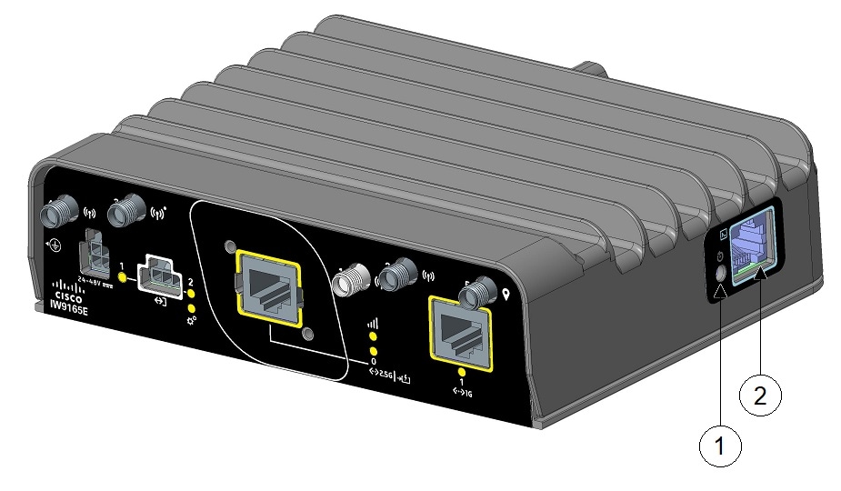
The following figure shows the available ports on the right-side panel of IW9165E.

Figure 1. IW9165E Right-Side Panel

1

Reset button

2

Console port (RJ-45)

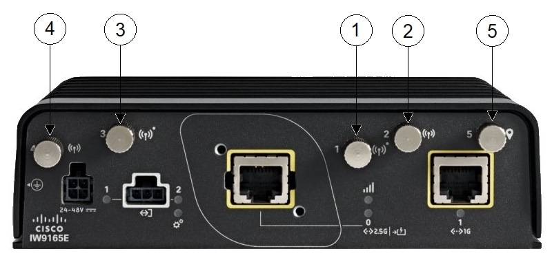
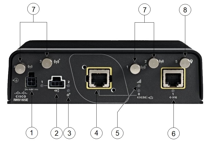
The following figure shows the available ports on the AP front panel.

Figure 2. IW9165E Front Panel

1

DC power input

5

RSSI Status LED

2

2 GPIO + 1 Return (Digital I/O)

Note


Digital I/O will be supported in a future software release.

6

100M/1000M/1G (RJ45)

3

System Status LED

7

Antenna ports

  • Antenna 1: 5 GHz and IoT radio

  • Antenna 2: 5 GHz

  • Antennas 3 and 4: 5/6 GHz

4

100M/1000M/2.5G Multigigabit Ethernet (RJ45)/M12 X-code autosensing PoE+ in (802.3af/at), Cisco UPOE in

8

GNSS port

Digital I/O Connector

The Digital I/O connector has 2 GPIO connections plus 1 Return connection. The Digital I/O supports Dry contacts.

Dry contact is isolated from a voltage source (or “No Volt”), with an embedded relay function (NPN transistor), usually used to indicate an event. For example: open/close, alarm.

The following graphic shows the connector.


Note


The default state of the Digital I/O is input, the open-collector is open (off).
Figure 3. Digital I/O connector

The pinouts for the Digital I/O are described in the following table.

Table 1. Digital I/O Pinouts

Pin #

Name

Direction

Description

1

DIO1

I/O

Digital IO 1

2

Return

Return

Digital IO Common Return

3

DIO2

I/O

Digital IO 2

Digital Input and Output Specifications are described in the following tables.

Digital Input Specification is considered “dry contact”.

Table 2. Digital Input Specification

Specification

Minimum

Maximum

Unit

Input Voltage High

2.5

60

Volts

Input Voltage Low

1.2

Volts

Input Current

12

1

mA

1 Current is flowing out of the terminal although it is an input, i.e. sourcing. The current is flowing in the terminal for the output, i.e. sinking.
Table 3. Digital Output Specification

Specification

Minimum

Maximum

Unit

Notes

Output Voltage High

2.5

Volts

No external voltage applied.

Output Voltage Low

0.4

Volts

No external voltage applied.

Internal Pull-up Resistance

220 – 1%

220 + 1%

Ohms

Internal Pull-up Voltage

3

Volts

External Pull-up Voltage

3.3

60

Volts

External resistance required to limit current to less than 100mA.

Sink Current

100

mA

Common features of the Digital I/O are:

  • Withstands up to 60V applied at the terminal.

  • Reverse voltage protected and causes no damage to the equipment.

  • Digital input and output can coexist on different channel.

  • LED Indicator: provision-able, On: Active, Off: Non-active.

  • Electrical isolation: 2000 VDC.

  • 4kV Surge protected (IEC 61000-4-5).

4-Pin Micro-Fit Connector for DC Power

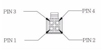
The following figure shows the 4-pin Micro-Fit connector for DC power.

Figure 4. Mating Connector Front View

Molex Micro-Fit Pin

Assignment

Pin 1

Black ( - Negative Terminal)

Pin 2

Not assigned

Pin 3

White (+ Positive Terminal)

Pin 4

Not assigned

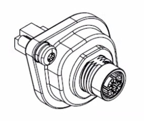
M12-RJ45 Adapter

M12-RJ45 adapter (Cisco PID: IW-ACC-M12ETH=) can be used to support M12 X-coded connector.


Note


M12 X-code port by using M12-RJ45 adapter can support up to 2.5G rate.


Note


The M12 spacer (Cisco PID: IW-ACC-M12SPCR2= ) is required when using the M12 adapter.


Figure 5. M12-RJ45 Adapter (Cisco PID: IW-ACC-M12ETH=)

The following table shows the M12-RJ45 adapter pinouts.

Table 4. M12-RJ45 Pinouts

RJ45

Signal

M12 X-Code

1

B1_DA+

1

2

B1_DA-

2

3

B1_DB+

3

6

B1_DB-

4

7

B1_DD+

5

8

B1_DD-

6

5

B1_DC-

7

4

B1_DC+

8

Power Sources

The IW9165E is supported on these power sources:

  • DC power: 24 to 48 VDC

  • Power over Ethernet (PoE): 802.3at (PoE+), 802.3bt (PoE++), Cisco Universal PoE (Cisco UPOE).


Warning


Statement 1033—Safety Extra-Low Voltage (SELV)—IEC 60950/ES1–IEC 62368 DC Power Supply

To reduce the risk of electric shock, connect the unit only to a DC power source that complies with the SELV requirements in the IEC 60950-based safety standards or the ES1 requirements in the IEC 62368-based safety standards.


Power Adapters

The IW9165E AP supports the following DC power adapters::

  • PID: IW-PWRADPT-MFIT4P=: Operating: -40°C to +65°C, 60W.

Power Injectors

The IW9165E AP supports the following power injectors:

  • IW-PWRINJ-60RGDMG=: Operating: -40°C to +70°C. Power derating of 60W at 70°C, and 65W at 65°C. Supports 100M/1G/2.5G/5G/10G rates.


Caution


When the AP is installed outdoors or in a wet or damp location, the AC branch circuit powering the AP should be provided with ground fault protection (GFCI), as required by Article 210 of the National Electrical Code (NEC).

Ethernet (PoE) Ports

The AP supports an Ethernet uplink port (also for PoE-IN). The Ethernet uplink port on the AP uses an RJ-45 connector to link the AP to the 100BASE-T, 1000BASE-T, or 2.5G BASE-T network. The Ethernet cable is used to send and receive Ethernet data and optionally supply inline power from the power injector or a suitably powered switch port.


Tip


The AP senses the Ethernet and power signals, and automatically switch internal circuitry to match the cable connections.

The Ethernet cable must be a shielded, Category 5e (CAT 5e) or better cable. The AP senses the Ethernet and power signals and automatically switches internal circuitry to match the cable connections.

Antennas and Radios

The Cisco Catalyst IW9165E Rugged Access Point and Wireless Client configuration is:

  • IW9165E-x

The IW9165E access point has four RP-SMA jack connectors to support multiple antenna options, such as the self-identifying antennas (SIA) on designated two SIA ports, dual-band antennas, and single-band antennas. To see the list of supported antennas and the radio bands they operate at, see Supported External Antennas.

Supported External Antennas

The following figure shows the antenna ports of the IW9165E access point.

Figure 6. IW9165E Antenna Ports

1

Port 1

Supports 5 GHz in 2x2 mode.

Supports Bluetooth Low Energy (BLE) radio.

Supports SIA.

4

Port 4

Supports 5/6 GHz radio in 2x2 mode.

2

Port 2

Supports 5 GHz radio in 2x2 mode.

5

GNSS port

3

Port 3

Supports 5/6 GHz radio in 2x2 mode.

Supports SIA.


Note


If omnidirectional antennas are connected to either radio, the antennas of each radio must be spaced at least 3 ft. (1 m) apart vertically to avoid interference between the two radios.

If directional antennas are connected to both radios, space them at least 10 ft. (3 m) apart vertically, or at least 5 ft. (1.5 m) apart horizontally with their main beams aimed at least 90 degrees apart.

If two independent omnidirectional antennas are connected to both ports of either radio (both ports 1 and 2 or ports 3 and 4), space them at least 2.5 in. (6 cm) apart for best performance.


Supported Wi-Fi Antennas

The following table shows the external Wi-Fi antennas supported by IW9165E.

Table 5. Supported Wi-Fi Antennas

PID

Antenna Gain (dBi)

Connector

Antenna Name

2.4 GHz

4.9 GHz

5 GHz

6 GHz

IW-ANT-PNL-515-N=

15

15

N female (x2)

Cisco 5 GHz 15 dBi Dual-Port Polarization Diverse Directional Panel Antenna

IW-ANT-OMV-2567-N=

4

7

7

7

N male

2.4/5 GHz Tri-Band Omnidirectional Dipole Antenna, Vertically Polarized, Self-Identifying

IW-ANT-OMH-2567-N=

4

7

7

7

N male

2.4/5 GHz Tri-Band Omnidirectional Dipole Antenna, Horizontally Polarized, Self-Identifying

AIR-ANT2547V-N=

4

7

N male

Cisco Aironet Dual-Band Omnidirectional Dipole Antenna (White)

AIR-ANT2547VG-N=

4

7

N male

Cisco Aironet Dual-Band Omnidirectional Dipole Antenna (Gray)

AIR-ANT2547VG-NS=

4

7

N male

Cisco Aironet Dual-Band Omnidirectional Dipole Antenna (Gray), Self-Identifying

AIR-ANT2568VG-N=

6

8

N male

Cisco Aironet Dual-Band Omnidirectional Dipole Antenna (Gray)

AIR-ANT2568VG-NS=

6

8

N male

Cisco Aironet Dual-Band Omnidirectional Dipole Antenna (Gray), Self-Identifying

AIR-ANT5180V-N=

7

8

N male

Cisco Aironet 5 GHz 8 dBi Omnidirectional Dipole Antenna

AIR-ANT2588P4M-NS=

9.1 (V), 7.1 (H)

9.6 (V), 7.8 (H)

N female (x4)

Cisco Aironet 2.4/5 GHz 8 dBi 4-Element Dual-Polarized Patch Antenna, Self-Identifying

AIR-ANT5114P2M-N=

14

N male (x2)

Cisco Aironet 5 GHz 13 dBi Dual-Port Dual-Polarized Directional Panel Antenna

AIR-ANT2513P4M-N=

13

13

N female (x4)

Cisco Aironet Four-Port Dual-Band Polarization-Diverse Directional Panel Antenna

AIR-ANT2513P4M-NS=

13

13

N female (x4)

Cisco Aironet Four-Port Dual-Band Polarization-Diverse Directional Panel Antenna, Self-Identifying

Supported URWB Antennas

The following table shows the URWB antennas supported by IW9165E.

Table 6. Supported URWB Antennas

PID

Antenna Gain (dBi)

Connector

Antenna Name

2.4 GHz

4.9 GHz

5 GHz

6 GHz

IW-ANT-OMM-53-N=

3

3

N female

5 GHz Omnidirectional Multi-Polarized Antenna

IW-ANT-OMV-55-N=

5

N female

5 GHz Vertically Polarized Omnidirectional Dipole Antenna

IW-ANT-OMH-55-N=

5

N female

5 GHz Horizontally Polarized Omnidirectional Dipole Antenna

IW-ANT-PNL-59-N=

9

N female (x2)

5 GHz Dual-Port Dual-Slant +/-45 Degree Polarized Directional Panel Antenna

IW-ANT-SKS-514-Q=

14

14

QMA female (x2)

5 GHz Directional Shark Antenna, Dual-Slant +/-45 Degree Polarized

IW-ANT-DS9-516-N=

15

15

N female (x2)

Dual-Slant Polarized Sector Antenna

IW-ANT-SS9-516-N=

15

15

N female (x2)

Dual-Linear Polarized Sector Antenna

IW-ANT-SKD-513-Q=

13

13

QMA female (x2)

5 GHz Bidirectional Shark Antenna, Dual-Slant +/-45 Degree Polarized

IW-ANT-PNL5615-NS=

15

15

15

N female (x2)

5/6 GHz 15 dBi Dual-Port Polarization Diverse Directional Panel Antenna, Self-Identifying

Supported GNSS Antenna

The following table shows the external GNSS antennas supported by IW9165E.

Table 7. Supported GNSS Antenna

PID

Frequencies Supported

Connector

Description

ANT-GNSS-OUT-TNC=

1560 - 1608 MHz

TNC male

Outdoor Active GNSS Antenna with 15-ft. integrated cable

IW-ANT-GNSS-SMA=

1559 - 1610 MHz

SMA male

Indoor/outdoor active GNSS antenna with 10-ft. integrated cable

For installation instructions and detailed information on any of these antennas, refer to the antenna data sheet on Cisco.com, or see the antenna guides at:

Follow all safety precautions when installing the antennas. For information on safety, see Safety Precautions when Installing Antennas.