- Overview
- Choosing the Right Access Point
- Physical Hardware and Mounting Options
- Understanding Flexible Radio Assignment (software overview)
- Client Roaming in a Micro and Macro Cell
- Approved Antennas for Use with Access Points 2800 and 3800
- AP 2800 and AP 3800 Powering Options
- AP 3800 and Multigigabit Ethernet (mGig)
- New–B Regulatory Domain for US Theater
- Stadium and Harsh Environments
- Areas with High Vibration
- Related References
- Frequently Asked Questions (FAQ's)
Choosing the Right
Access Point
- Models
- Part Numbers and Descriptions
- Supported Code Versions Compatible with AP 2800 and AP 3800
- Differences between the AP 2800 and AP 3800 Access Points
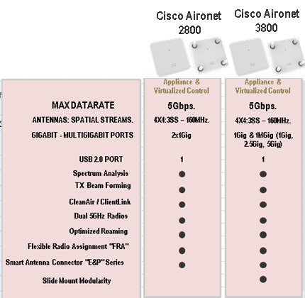
- Feature Differences
- Ports on the AP 2800 and AP 3800
- Modularity and Smart Antenna Connector Ports
Models
The Cisco 2800 and 3800 Series Access Points target customers requiring support for mission-critical and best in class applications. The 2800/3800 embodies ClientLink 4.0, an innovative antenna technology comprising four transmit radios and four receive radios called 4x4 in a Multiple Input Multiple Output (MIMO) configuration and supporting three spatial streams (3SS), together referenced as 4x4:3. Using this type of antenna system along with additional Modulation Coding Scheme (MCS) rates supporting up to 256 QAM and up to 160 MHz channel bonding, rates of up to 5 Gbps can be supported.
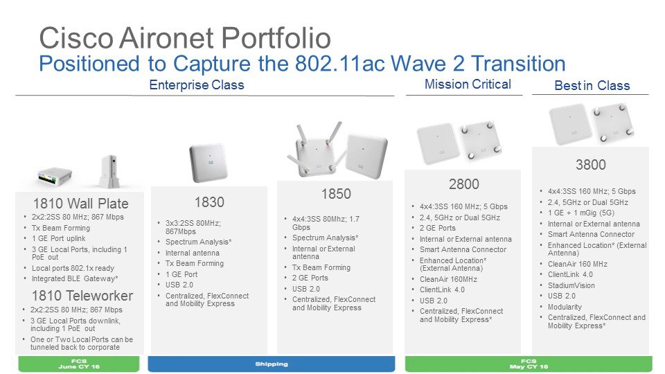
Access points are available in three models:
-
Internal antennas version labeled “i” that has captured antennas (part of the housing and not removable). The “i” series is designed for indoor Enterprise installations where office aesthetics are a primary concern.
-
External antennas version labeled “e” that is more rugged and designed for industrial use in locations such as hospitals, factories, and warehouses, anywhere a need exists for external antennas and/or extended operating temperatures. The “e” version also supports mounting inside NEMA enclosures for use in the most demanding environments.
-
Access points for professional install are labeled “p” series and may be used in outdoor applications.
Part Numbers and Descriptions
|
SKU |
Description |
|---|---|
|
AIR-AP3802I-x-K9 |
Single Unit; Internal Antenna Model |
|
AIR-AP3802I-xK910 |
10 pack; Internal Antenna Model |
|
AIR-AP3802E-x-K9 |
Single Unit; External Antenna Model |
|
AIR-AP3802E-xK910 |
10 pack; External Antenna Model |
|
AIR-AP3802I-x-K9C |
Single Unit; Internal Antenna Model; Configurable |
|
AIR-AP3802I-xK910C |
10 pack; Internal Antenna Model; Configurable |
|
AIR-AP3802E-x-K9C |
Single Unit; External Antenna Model; Configurable |
|
AIR-AP3802E-xK910C |
10 pack; External Antenna Model; Configurable |
Supported Code Versions Compatible with AP 2800 and AP 3800
The minimum versions supporting the AP 2800 and 3800 are:
Differences between the AP 2800 and AP 3800 Access Points
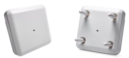
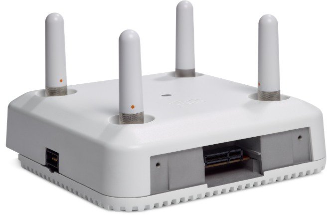
The mechanical front of the AP 2800 and AP 3800 are nearly identical in physical appearance.
The AP 3800 is also available in a "P" version. The external antenna "E" versions permit antenna gains up to 6 dBi, "P" version up to 13 dBi.
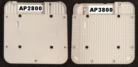
There are slight differences in the weight and thickness of the 2800 and 3800. The AP 3800 is a bit more robust as it has support for mGig (NBASE-T) and optional module support. AP 2800 on left is smooth and does not have heat fins.
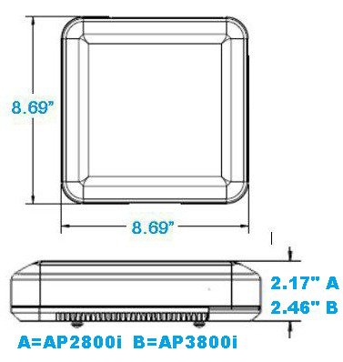
Depending on the model the thickness changes slightly.
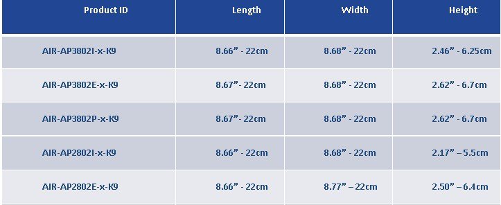
 Note | The weight is slightly different between the models.AP 3800 both “E” and “P” versions as well as the 2800e is 2.1 kg.AP 3800i is 2.0 kg. AP 2800i is 1.6 kg. |
Both products use the same brackets as 2700/3700 2700/3700 Series Access Points–AIR-AP-BRACKET1 and AIR-AP-BRACKET-2.
Feature Differences
Here is a basic feature comparison:
Ports on the AP 2800 and AP 3800
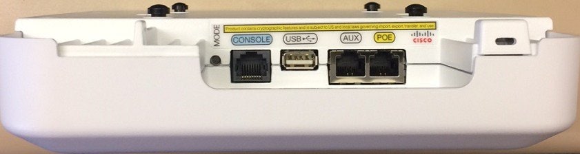
The AP 2800 is similar to the AP 3800 but lacks a local power supply input and mGig PoE port. Additionally, the USB port is mounted sideways.
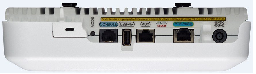
The AP 3800 has a local power supply jack on the right; This is a new style connector and is not compatible with the older AIR-PWR-B power supplies used with the AP 2700 and AP 3700 series. For more on this connector, see the powering section for details.
In addition there is an mGig port as well as a port for external modules on the AP 3800.
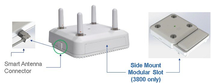
Modularity and Smart Antenna Connector Ports
The AP 3800 has modularity support that is a bit different from the original module design on the prior AP 3600 and AP 3700 series. This module design allows for installation onto the side of the access point. This allows for larger antenna arrays and does not constrict the development of Cisco and potentially third party modules as they are no longer limited by the physical size of the cccess point. Additionally, filtering is installed on the AP 3800 for cellular and other radio coexistence.
The external antenna connectors on the "E" and "P" series are identical to the antenna connectors on previous access points. There is no difference in operation when the access point is used in dual band (2.4 and 5 GHz) operation. which is the default mode. RF coverage and cell sizes are similar to the previous AP 2700 and 3700 series so there is no need to do a new site survey.
Unlike the prior external antenna versions, the new 2800 and 3800 series Access Points now support the capability of dual 5–GHz operation. When in this mode, a smart antenna connector must be used on the external antenna models, as the additional 5–GHz radio cannot use the same top antennas on the access point that are being used by the primary 5–GHz radio.
When a smart antenna connector is installed, the XOR radio (the radio that is defined in software as Radio 0) now has its RF switched to the smart antenna connector.
 Feedback