- Preface
- Product Overview
- Getting Started
- Deploying Cisco Mobility Express Solution
- Creating DHCP Scopes for Wireless Networks
- Configuring Mobility Express for Site Survey
- Creating Wireless Networks
- Managing WLAN Users
- Managing Access Points
- Managing the Mobility Express Network
- Using Advanced Settings
- Primary AP Failover and Electing a New Primary
- Cisco Mobility Express with Cisco CMX Cloud
- Managing Mobility Express Deployments from Cisco Prime Infrastructure
- Pre-requisites for Deploying Mobility Express Solution
- Connecting Cisco Mobility Express Capable Access Point
- Determining the image on the Access Point
- Conversion
- Configuring Mobility Express Controller using Over-the-Air Setup Wizard
- Configuring Mobility Express Controller using Startup Wizard from CLI
- Logging into Mobility Express Controller
Deploying Cisco
Mobility Express Solution
Pre-requisites for Deploying Mobility Express Solution
-
You must not have other Cisco Wireless LAN Controllers; neither appliance nor virtual in the same network during set up or during daily operation of a Cisco Mobility Express network. The Mobility Express controller cannot interoperate or co-exist with other Wireless LAN Controllers in the same network.
-
Decide on the first Access Point to be configured as a Master Access Point. This Access Point should be capable of supporting the Wireless LAN Controller function.
-
DHCP Server: A DHCP server must be configured so that Access Points and clients can obtain an IP Address and gateway assigned is reachable at all times.
Connecting Cisco Mobility Express Capable Access Point
To connect Cisco Mobility Express capable access point, perform the following steps:
Determining the image on the Access Point
The Cisco 1830, 1850, 2800 and 3800 series access points can either have CAPWAP image or the Cisco Mobility Express image which is capable of running the virtual Wireless LAN controller function on the Access Point.
To determine the image and capability of an Access Point, follow the steps below:
| Step 1 | Login to the Access Point CLI using a console and type AP#show version and check the full output of show version. The default login credentials are Username:cisco and Password:cisco. | ||
| Step 2 | If
show version
output
does not display
AP Image
Type and
AP
Configuration parameters as highlighted below, it means that AP is running
the CAPWAP image and a conversion to Cisco Mobility Express is required if you
want to run the controller function on the Access Point. To convert from a
CAPWAP Access Point to Mobility Express, go to Conversion section.
cisco AIR-AP1852E-UXK9 ARMv7 Processor rev 0 (v71) with 997184/525160K bytes of memory. Processor board ID RFDP2BCR021 AP Running Image : 8.2.100.0 Primary Boot Image : 8.2.100.0 Backup Boot Image : 8.1.106.33 AP Image type : MOBILITY EXPRESS IMAGE AP Configuration : MOBILITY EXPRESS CAPABLE 0 Gigabit Ethernet interfaces 0 802.11 Radios Radio FW version . 1401b63d12113073a3C08aa67f0c039c0 NSS FW version : NSS.AK.1.0.c4-0Z026-E_cust C-1.24160 | ||
| Step 3 | If the
show version
displays
AP Image Type:
MOBILITY EXPRESS IMAGE and
AP
Configuration:
NOT
MOBILITY EXPRESS CAPABLE, it means that even though the Access Point has
the Cisco Mobility Express image, it is configured to run only as a CAPWAP
Access Point. Such an Access Point will not run the controller function and
will not participate in the Master Election process upon failure of the active
Master AP.
cisco AI R-AP1852E-UXK9 ARMv7 Processor rev 0 (v7I) with 997184/726252K bytes of memory.
Processor board ID RFDP2BCR021
AP Running Image : 8.2.101.0
Primary Boot Image : 8.2.100.0
Backup Boot Image : 8.1.106.33
AP Image type : MOBILITY EXPRESS IMAGE
AP Configuration : NOT MOBILITY EXPRESS CAPABLE
For this AP to run the controller function, execute the following command from the AP CLI. AP#ap-type mobility-express tftp:// |
Conversion
 Note | On 1830 and 1850 Series Access points, conversion from CAPWAP to Mobility Express is supported from Release 8.1.122.0 and later but it is recommended to have CAPWAP version 8.2.100.0 on the Access Point prior to converting from CAPWAP to Mobility Express. If the CAPWAP image on the Access Point is prior to 8.2.121.0, Access Point MUST first join a WLC running 8.2.100.0 or higher to upgrade its CAPWAP image. After the CAPWAP image of the AP has been upgraded, conversion of AP from CAPWAP to Mobility Express can be performed. |
 Note | On 2800 and 3800 series Access Points, Mobility Express is supported starting Release 8.3.102.0 so they must have 8.3.102.0 CAPWAP image before they can be converted to Mobility Express. If the CAPWAP image on the Access Point is prior to 8.3.102.0, Access Point MUST first join a WLC running 8.3.102.0 or higher to upgrade its CAPWAP image. After the CAPWAP image of the AP has been upgraded, conversion of AP from CAPWAP to Mobility Express can be performed. |
The following conversions are supported:
- Converting a CAWAP AP to Mobility Express–This conversion is required when you have an access point running CAPWAP image, and you want to use them to deploy a Mobility Express network. For this, you would convert the CAPWAP AP to a Master AP (runs controller function in a Mobility Express network).
-
Converting a Mobility Express capable AP to CAPWAP AP - There are two reasons for this conversion:
| Step 1 | Download the
conversion image for the Access Point from cisco.com to the TFTP server. It is
a tar file. Do not untar the file
The following table lists the Cisco Mobility Express software for Cisco Wireless Release 8.3.102.0.
| |||||||||||||||
| Step 2 | Login to the Access Point CLI using a console and type AP#show version and check the full output of showversion. The default login credentials are Username:cisco and Password:cisco |
Converting a CAWAP AP into a Mobility Express AP
To convert an access point running CAPWAP image into a Mobility Express capable image, you have to download and install the Mobility Express image from a TFTP server. A single CLI command has been provided to download the Mobility Express image from a TFTP server and convert the AP Configuration to MOBILITY EXPRESS CAPABLE.
-
A TFTP server with Mobility Express image. See Procedure below.
-
A DHCP server to assign an IP address to the Cisco access point.
-
The Cisco 1800 series access point must not join any existing controller in the network when you are trying to load Mobility Express image. If you have an existing controller on your network to which the AP can join, conversion is not successful.
To convert an AP running CAPWAP image to Mobility Express, perform the following steps:
| Step 1 | Enter enable to go to privileged execution mode. | ||
| Step 2 | Enter
show
version on the Access Point CLI. From the
show
version output, you can determine the
AP Image
type and
AP
Configuration and can then proceed with the conversion process.
| ||
| Step 3 | Enter the
command below to change the
AP
Configuration to
MOBILITY EXPRESS
CAPABLE.
AP#ap-type mobility-express tftp://<TFTP Server IP>/<path to tar file> Since the Access Point has an AP Image type: MOBILITY EXPRESS IMAGE; a new image does not be downloaded. After the command is issued, the Access Point reboots and comes up as AP Configuration MOBILITY EXPRESS CAPABLE . | ||
| Step 4 | If
AP Image
Type and
AP
Configuration is not available in show version, it means that the AP is
running
CAPWAP
image. To do the conversion, execute the command below:
AP#ap-type mobility-express tftp://<TFTP Server IP>/<path to tar file>Example: AP#ap-type mobility-express tftp://10.18.22.34/AIR-AP1850-K9-8.1.120.0.tar Starting the ME image download... It may take few minutes to finish the download.
Image downloaded, writing to flash... do PREDOWNLOAD, part1 is active part sh: CHECK_ME: unknown operand Image start 0x40355008 size 0x01dae41a file size 0x01dae7ca Key start 0x42103422 size 0x00000230 Sinature start 0x42103652 size 0x00000180 Verify returns 0 btldr rel is 16 vs 16, does not need update part to upgrade is part2 activate part2, set BOOT to part2 AP primary version: 8.1.105.37 Archive done. Oe as AP needs to boot up with ME image The system is going down Now! sent SIGTERM to all processes sent SIGKILL to all processes Requesting system reboot79] [07/24/2015 18:19:43.0887] Restarting system. [07/24/2015 18:19:43.1257] Going down for restart now | ||
| Step 5 | After AP reboots, Mobility Express starts in Day 0 and CiscoAirProvison SSID is broadcast. |
Converting a Mobility Express AP into a CAPWAP AP
When the AP type is CAPWAP, AP cannot run the controller function and cannot participate in the Master AP election process.
After changing the AP Type, if this AP is migrated to another WLC network (non-Mobility Express network), it joins the controller in that network. If the image on the WLC is different than the one on the AP, a new CAPWAP image is requested from the WLC.
When the AP type is CAPWAP (as required for this conversion), the AP doesn’t start its own controller function and when the AP joins the external controller, a new image is requested from the controller and the AP gets the CAPWAP image.
To convert the Mobility Express AP into the CAPWAP AP, perform the following steps:
| Step 1 | Login to the Access Point CLI . |
| Step 2 | Type Enable to go to privileged execution mode. |
| Step 3 | Enter
ap#ap-type capwap
and confirm to switch to the CAPWAP type.
To convert multiple 1800 series access points running Mobility Express image to CAPWAP simultaneously from the Mobility Express controller CLI, execute the following command: (Cisco Controller) >config ap unifiedmode <switch_name> <switch_ip_address> <switch_name> and <switch_ip_address> is the name and IP address respectively of the WLC to which the APs need to be migrate. The above command converts all Cisco 1800 APs connected to the Mobility Express with AP Configuration: MOBILITY EXPRESS CAPABLE to AP Configuration: NOT MOBILITY EXPRESS CAPABLE. When this command is issued the APs are reloaded, and they come back up in local mode. |
Configuring Mobility Express Controller using Over-the-Air Setup Wizard
To configure the Mobility Express using Over-the-Air Setup wizard, perform the following steps:
| Step 1 | When a LED
chirps green, connect a WiFi enabled laptop, through Wi-Fi, to the
CiscoAirProvision
SSID. The default password is
password.
The laptop gets an IP address from subnet 192.168.1.0/24.
| ||||||||||||||||||||||||||||||||
| Step 2 | Open a browser
and go to
http://192.168.1.1 which redirects to the initial
configuration wizard.
The initial configuration wizard's admin account page appears. 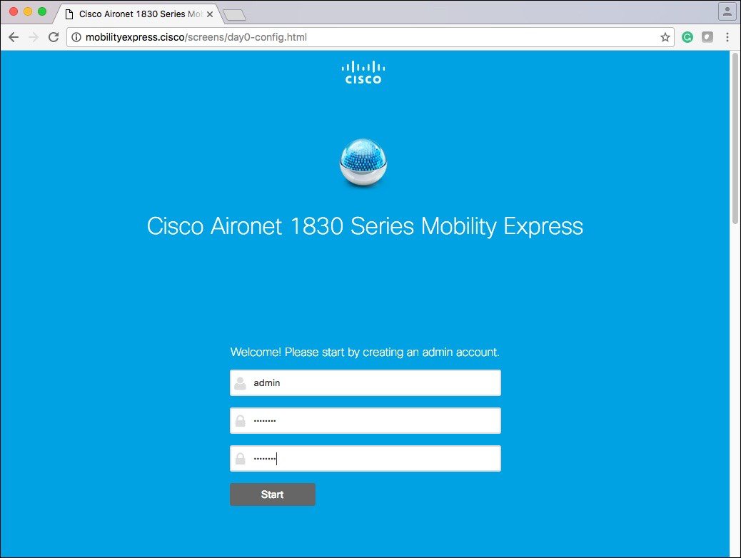 The banner on the opening page shows the name of the AP model on which the Mobility Express wireless LAN controller is being configured. For example, 'Cisco Aironet 1850 Series Mobility Express'.
| ||||||||||||||||||||||||||||||||
| Step 3 | Create an admin
account on the controller by specifying the following parameters and then click
Start.
| ||||||||||||||||||||||||||||||||
| Step 4 | Set up your
controller by specifying the values.
On the Set Up Your Controller screen, using the checklist, specify the following:
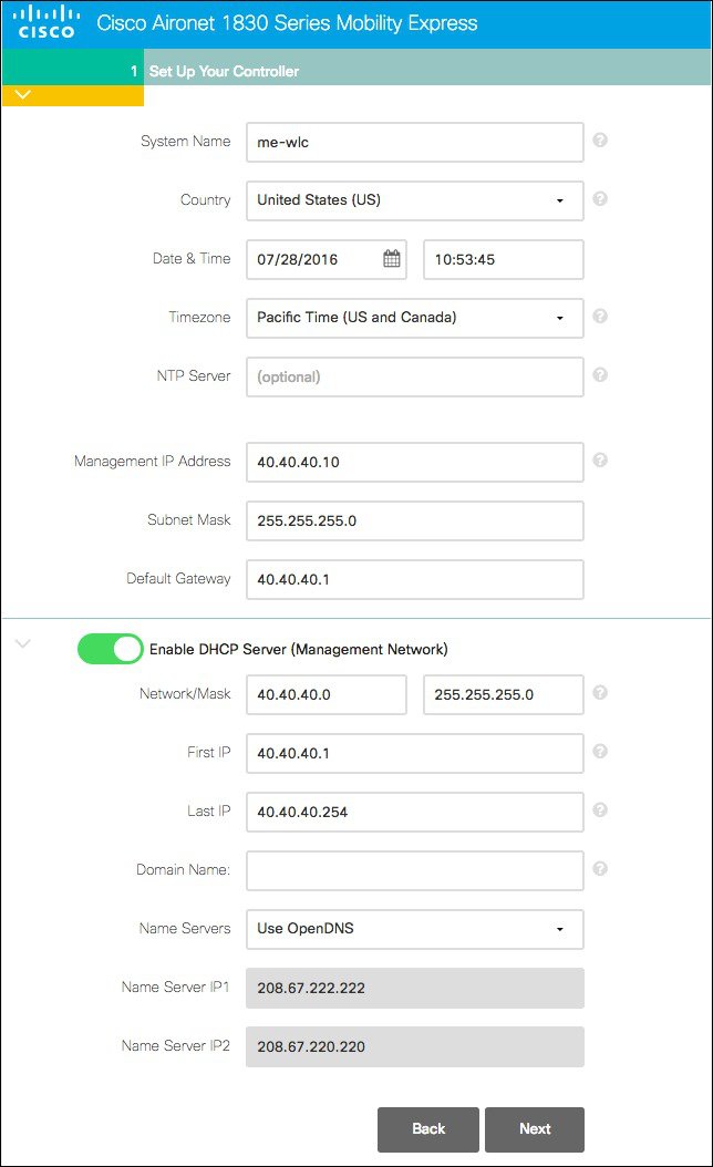 | ||||||||||||||||||||||||||||||||
| Step 5 | Click Next. | ||||||||||||||||||||||||||||||||
| Step 6 | Create the
Employee wireless network by specifying the following fields:
| ||||||||||||||||||||||||||||||||
| Step 7 | Enable
the Guest
Network slider and specify the following parameters:
 | ||||||||||||||||||||||||||||||||
| Step 8 | Click Next. | ||||||||||||||||||||||||||||||||
| Step 9 | In the
Advanced Settings tab, enable
RF Parameter
Optimization slider and optimize by indicating the expected client density
and traffic type in your network.
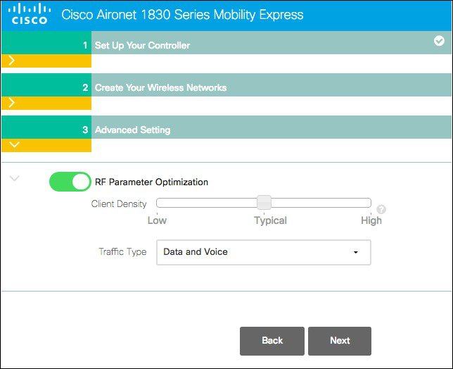 The
following table depicts the default values when low, typical, or high
deployment type is selected from RF parameters
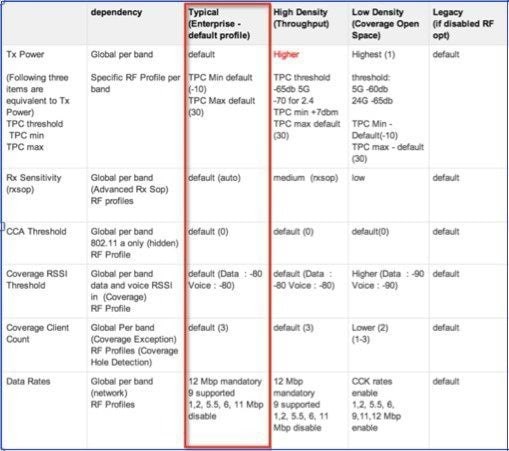 | ||||||||||||||||||||||||||||||||
| Step 10 | Select
Traffic Type and click
Next to
continue.
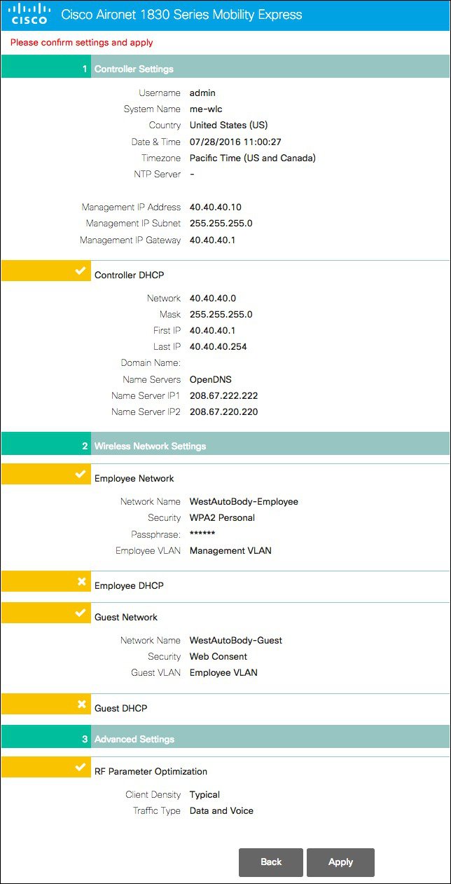
A confirmation screen displays the summary of the configuration. | ||||||||||||||||||||||||||||||||
| Step 11 | Click
Apply, if
all the settings are correct
| ||||||||||||||||||||||||||||||||
| Step 12 | Click
OK to
reboot.
|
Configuring Mobility Express Controller using Startup Wizard from CLI
Console Connection
Before you can configure the AP to Mobility Express Controller, connect to the port marked ‘CONSOLE’ using SecureCRT, Putty or similar applications. The default parameters for the console ports are 9600 baud, eight data bits, one stop bit, and no parity. The console ports do not support hardware flow control. Choose the serial baud rate of 9600.
Startup Wizard from CLI
System Name [Cisco_2c:3a:40] (31 characters max): me-wlc
Enter Country Code list (enter 'help' for a list of countries) [US]:

Configure a NTP server now? [YES][no]: no
Configure the system time now? [YES][no]: no

Note! Default NTP servers will be used

Management Interface IP Address: 40.40.40.10
Management Interface Netmask: 255.255.255.0
Management Interface Default Router: 40.40.40.1
Cleaning up Provisioning SSID
Create Management DHCP Scope? [yes][NO]: yes
DHCP Network : 40.40.40.0
DHCP Netmask : 255.255.255.0
Router IP: 40.40.40.1
Start DHCP IP address: 40.40.40.11
Stop DHCP IP address: 40.40.40.254
DomainName :
DNS Server : [OPENDNS][user DNS]
Create Employee Network? [YES][no]: YES
Employee Network Name (SSID)?: WestAutoBody-Employee
Employee VLAN Identifier? [MGMT][1-4095]: MGMT
Employee Network Security? [PSK][enterprise]: PSK
Employee PSK Passphrase (8-38 characters)?: Cisco123
Re-enter Employee PSK Passphrase: Cisco123
Create Guest Network? [yes][NO]: YES
Guest Network Name (SSID)?: WestAutoBody-Guest
Guest VLAN Identifier? [EMPLOYEE][1-4095]: EMPLOYEE
Guest Network Security? [WEB-CONSENT][psk]: WEB-CONSENT
Create Guest DHCP Scope? [yes][NO]: NO
Enable RF Parameter Optimization? [YES][no]: YES
Client Density [TYPICAL][Low][High]: TYPICAL
Traffic with Voice [NO][Yes]: Yes

Configuration correct? If yes, system will save it and reset. [yes][NO]: yes
Cleaning up Provisioning SSID
 Note | After the AP has finished rebooting, login to the Mobility Express controller WebUI using the Management IP address. |
Logging into Mobility Express Controller
To log in to the Mobility Express, perform the following steps:
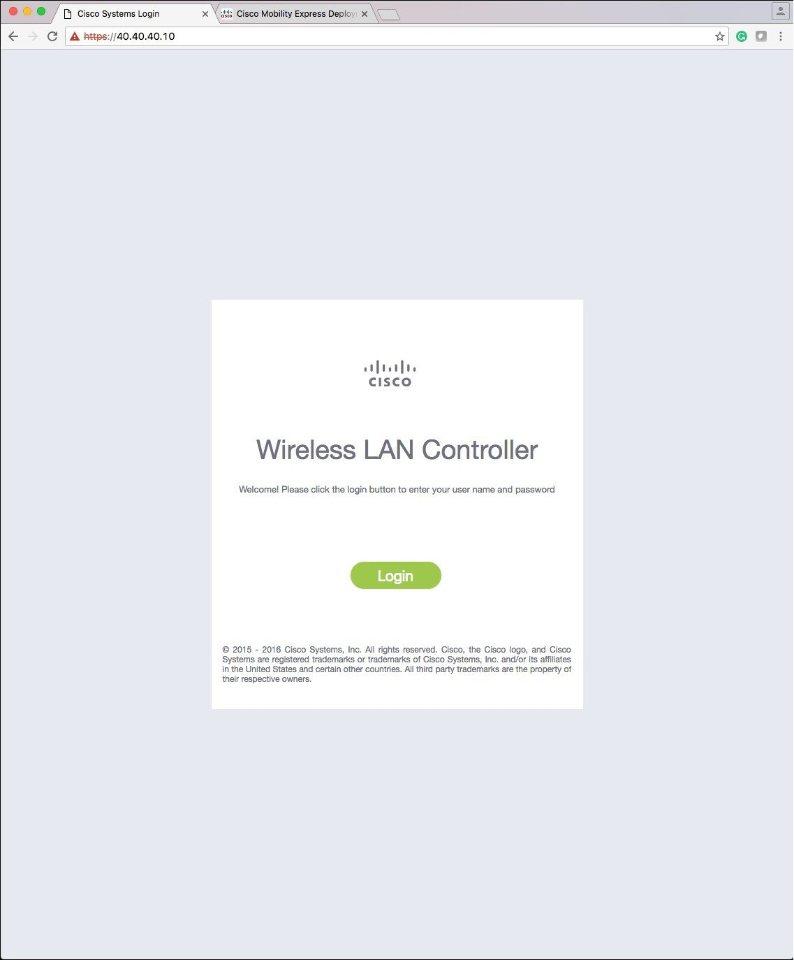
| Step 1 | Enter the IP
address of the Mobility Express management interface in the web browser.
The
Cisco
Wireless LAN Controller window appears.
 | ||
| Step 2 | Click
Login.
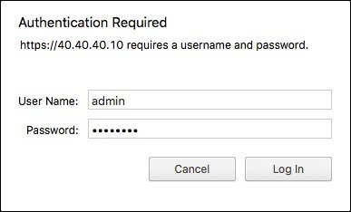 | ||
| Step 3 | Enter the
administrator user name and password.
|
 Feedback