Cisco Catalyst 9800 Series Configuration Best Practices
Available Languages
Bias-Free Language
The documentation set for this product strives to use bias-free language. For the purposes of this documentation set, bias-free is defined as language that does not imply discrimination based on age, disability, gender, racial identity, ethnic identity, sexual orientation, socioeconomic status, and intersectionality. Exceptions may be present in the documentation due to language that is hardcoded in the user interfaces of the product software, language used based on RFP documentation, or language that is used by a referenced third-party product. Learn more about how Cisco is using Inclusive Language.
- US/Canada 800-553-2447
- Worldwide Support Phone Numbers
- All Tools
 Feedback
 Feedback
Cisco Catalyst 9800 Series new configuration model
Cisco Catalyst 9800 Series profile and tag considerations
Moving APs between controllers and preserving tags
Designing for large scale deployments
General C9800 Wireless Controller settings
Support for jumbo frames and the “ip mtu” interface command
Configuration requiring controller reload or network down
Configuration: special characters
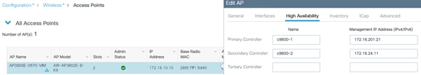
Configure predictive join: Primary/Secondary/Tertiary controller
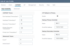
Primary/secondary/tertiary versus backup primary/backup secondary
Access Point Console Baud Rate
Cisco Discovery Protocol (CDP) for Access Points
Spanning Tree Protocol (STP) setting on uplink ports
Prune VLANs on controller uplink ports
Address Resolution Protocol (ARP) proxy
DHCP Scope and Lease design considerations
Wireless management IP addressing
Wireless management interface VLAN tag
Use of VLAN 1 in a Policy Profile
Preventing traffic leaks for guest or AAA override scenarios
APs and Wireless Management Interface VLAN
AP-to-controller round-trip latency
Use PortFast on AP switch ports
Prune VLANs for FlexConnect mode AP switch ports
Voice Cisco Centralized Key Management timestamp validation
Application Visibility and Control
Enable 802.11k for optimal roaming
Anchoring an SSID and broadcasting it to local APs
Trustpoint and Cisco Catalyst Center
Local management password policies
Disable Management via Wireless
Default AP console username and password
802.1X authentication for AP ports
Enable 802.11r Fast Transition
Wireless management VLAN mapping to WLAN (via policy profile)
AAA VLAN and Fabric VNID Override
EAP Identity request timeout and maximum retries
EAP request timeout and maximum retries
EAPoL key timeout and maximum retries
RADIUS Network Device configuration
Rogue management and detection
Define appropriate malicious rogue AP rules
Identify and update friendly rogue AP list
AP Rogue Detection Configuration
Enable rogue client AAA validation
Rogue Location Discovery Protocol
Rogue Notifications and Telemetry
SSO HA with C9800-CL and vMware vMotion
Returns & Replacements (RMA) replacement procedure for SSO pair
Aggregated probe response optimization
DCA and Dynamic Frequency Selection
DCA and Flexible Radio Assignment
Inter-controller Layer 2 versus Layer 3 roaming
Reduce the need for inter-controller roaming
Inter-release controller roaming
Migration from AireOS WLC to C9800
Mobility groups and Secure Mobility
Moving APs between an AireOS WLC and the C9800
Wireless QoS for the Catalyst 9800 Wireless Controller
Verifying the QoS settings on the Catalyst 9800
Perform an RF active site survey and estimate the coverage
Avoid selecting DFS channels for backhaul
Deploy multiple RAPs in each BGN
C9800 Managed by Prime and Catalyst Center
July 10, 2026
● Updated sections
◦ Updated section Anchoring an SSID and broadcasting it to local APs to clarify a roaming scenario
◦ Updated section RF Groups to correct the values for CW9800M
◦ Updated section Internal DHCP server to clarify support for DHCPv6
June 22, 2026
● Updated sections
◦ Updated section DHCP Required to include the latest recommendations for Fabric wireless.
May 29, 2026
● Updated sections
◦ Updated section Stateful Switchover (SSO) to include the latest recommendations
May 12, 2026
● Updated sections
◦ Updated section Rogue Notifications and Telemetry to include the latest recommendations
April 17, 2026
● Updated sections
◦ Updated section WPA3 to include the latest recommendations
April 9, 2026
● Updated sections
◦ Updated section WebAuth and WebUI to include more detailed recommendations
March 17, 2026
● Updated sections
◦ Updated section Aironet IE to include the latest changes
January 16, 2026
● Updated sections
◦ Updated section WPA3 to include the latest recommendations
December 19, 2025
● New sections
◦ Added section RADIUS Network Device configuration
November 27, 2025
● New sections
◦ Added section AP load balancing summary
◦ Added section Support for jumbo frames and the “ip mtu” interface command
◦ Added section Global use access points
◦ Added section AP Fallback to Primary
◦ Added section Cisco Discovery Protocol (CDP) for Access Points
◦ Added section DHCP Scope and Lease design considerations
◦ Added section 802.11v
◦ Added section WPA3
◦ Added section WebAuth
◦ Added section RADIUS interim accounting
◦ Added section 6 GHz Design
◦ Added section High throughput
● Updated sections
◦ Updated section Enhance your design with the RF based Automatic AP Load Balancing
◦ Updated section Primary/secondary/tertiary versus backup primary/backup secondary explaining the different timers
◦ Updated section Dealing with trustpoints with correct commands and updated screenshots
◦ Updated section Reducing the number of SSIDs to clarify the maximum number of SSID per band recommended
◦ Updated section RF Groups to include a note about RF Group name
● Other changes
◦ Included specifications for new CW9800 controllers
May 3, 2024
● New sections
◦ Designing for Large Scale Deployments: APs to WNCd mapping, site tags design, features, and recommendations
◦ Access Point Console Baud Rate: Changes and recommendations with changes coming in 17.12.1 and above
● Updated sections
◦ Use of the Service Port: Updated the list of supported protocols
◦ Wireless client interfaces: Recommendations around access control lists (ACLs) on Client SVIs
◦ Client Timers: Revised recommendations for session and exclusion timeout
◦ Enable 802.11r Fast Transition: Updated recommendation to set 802.11r mixed mode instead of adaptive 802.11r
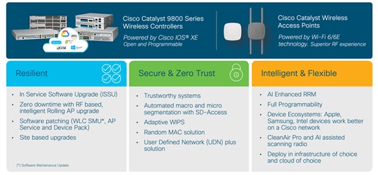
The Cisco® Catalyst® 9800 Series (C9800) is the next-generation wireless LAN controller from Cisco. It combines RF excellence gained in 25 years of leading the wireless industry with Cisco IOS® XE software, a modern, modular, scalable, and secure operating system. The Catalyst Wireless solution is built on three main pillars of network excellence: Resiliency, Security, Intelligence.
Compared to the AireOS WLC, the C9800 software has been rewritten from scratch to leverage the benefits of Cisco IOS XE, and the configuration model has been made more modular and flexible. This means that, although most AireOS features are retained, there might be changes in the way you configure certain functionalities.
This document covers the best practices recommended for configuring a typical Cisco Catalyst 9800 Series wireless infrastructure. The objective is to provide common settings that you can apply to most wireless network implementations. But not all networks are the same. Therefore, some of the tips might not be applicable to your installation. Always verify them before you perform any changes on a live network.
The first part of the document focuses on some important configuration and design concepts of the Catalyst 9800 Wireless Controller. These will be useful to understand the best practices presented in the rest of the document. The guide is a list of recommended configurations organized in sections: General, Network, Radio Frequency (RF), Security settings and more.
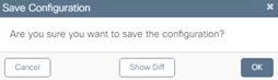
When available, these settings are shown using the new graphical user interface (GUI) of the Catalyst 9800, as it has been greatly improved and should be easy to navigate. If you want to know what command-line interface (CLI) commands correspond to a certain GUI setting, the C9800 provides a very useful and easy way: apply the desired setting via the GUI and then click the Save icon in the top right corner ![]() . In the next popup window select Show Diff.
. In the next popup window select Show Diff.
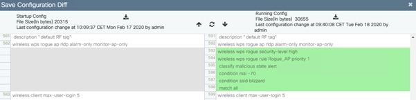
This will open up another window where you can compare the existing and new configuration. The commands that are different are highlighted: green indicates new commands, orange modified commands, and red deleted commands. Below is an example for a new rogue management setting.
Each recommended setting will be highlighted if there are some known restrictions or if it applies to a specific release of code. The differences with AireOS will also be underlined.
The information in this document is derived from tests on devices in specific lab environments. All of the devices used in this document started with a cleared (default) configuration. If your network is live, make sure that you understand the potential impact of any command.
Cisco recommends that you have knowledge of these topics:
● Cisco wireless compatibility matrix for the latest on the supported compatible releases: https://www.cisco.com/c/en/us/td/docs/wireless/compatibility/matrix/compatibility-matrix.html and the latest on the features supported on access points: https://www.cisco.com/c/en/us/td/docs/wireless/access_point/feature-matrix/ap-feature-matrix.html
● Cisco publishes the list of IOS XE recommended releases here: https://www.cisco.com/c/en/us/support/docs/wireless/catalyst-9800-series-wireless-controllers/214749-tac-recommended-ios-xe-builds-for-wirele.html
● Always check the release notes for the specific software you plan to implement: https://www.cisco.com/c/en/us/support/wireless/catalyst-9800-series-wireless-controllers/products-release-notes-list.html
● New Cisco Catalyst 9800 Wireless Controllers Configuration Model. More information can be found here: https://www.cisco.com/c/en/us/support/docs/wireless/catalyst-9800-series-wireless-controllers/213911-understand-catalyst-9800-wireless-contro.html
● Most of the features covered in this document are documented either in the configuration guides: https://www.cisco.com/c/en/us/support/wireless/catalyst-9800-series-wireless-controllers/products-installation-and-configuration-guides-list.html
or in the technical references:
The information in this document is based on the following software and hardware versions:
● Cisco Catalyst 9800 Series Wireless Controller platforms: all platforms unless explicitly called out. This also includes CW9800 platforms.
● Cisco Catalyst 9800 Series Wireless Controller software: the recommendations are valid for every release unless explicitly called out.
● Cisco 802.11be (Wi-Fi 7), 802.11ax (Wi-Fi 6 and 6E) and 802.11ac (Wi-Fi 5) access points.
Cisco Catalyst 9800 Series new configuration model
A quick recap first. The Cisco Catalyst 9800 Series new configuration model is based on two constructs: profiles and tags. Profiles group a set of features and functionalities, and tags allow you to assign these features and functionalities to APs. There are five types of profiles:
● AP Join profile or AP profile: Contains general AP settings such as Control and Provisioning of Wireless Access Points (CAPWAP) timers, 802.1X supplicant, SSH/Telnet settings, and many more. These settings in AireOS are usually global configurations for all the APs.
● WLAN profile: Defines the SSID name and profile and all the security settings.
● Policy profile: Contains policy features to be associated with the WLAN. It specifies the settings for client VLAN, authentication, authorization, and accounting (AAA), access control lists (ACLs), session and idle timeout settings; and so on.
● Flex profile: Groups all settings to be assigned to a Flex AP: native VLAN, ACL mapping, and so on.
● RF profile: As in AireOS, it defines the RF characteristics of each band.
The tag allows you to bind the settings in the profiles to an access point. There are three types of tags:
● Policy tag: Ties together the Policy profile and the WLAN.
● Site tag: Assigns the AP Join profile settings to the AP and determines if the site is a local site, in which case the APs will be in local mode, or not a local site, in which case the APs will be in Cisco FlexConnect® mode.
● RF tag: Binds the 6-GHz, 5-GHz and 2.4-GHz profiles to the AP.
An access point is always assigned three tags, one for each type. If a tag is not explicitly defined, the AP will get the default policy, site, or RF tag.
The C9800 configuration model allows the customer to have much more flexibility in tweaking the configuration to fit a specific wireless deployment. Let’s take the TCP MSS Adjust setting as an example: In AireOS this is a global setting, so the same value is either applied to all the APs at each location or is left as the default. With the new configuration model, the TCP MSS Adjust value is set at the AP Join profile level, so the customer can evaluate the transport network at each site and decide the value that is best for a specific group of APs. This applies to all the settings, and it’s a great value add.
Cisco Catalyst 9800 Series profile and tag considerations
As just described, with the C9800, some configurations are done differently than in AireOS, with the intent of making the settings more flexible and easier to use. Functionalities that you are used to in AireOS wireless controllers are also supported in the C9800, but you need to get familiar with the configuration model in order to have them. Plus the new configuration model is made to be extended to the new differentiating features supported by the C9800.
The following sections describe best practices for profiles and tags and give some tips on how to best use them.
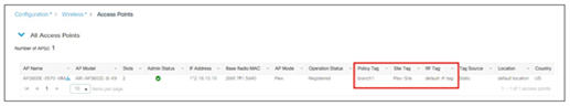
Each access point needs to be assigned three unique tags: a policy, site, and RF tag. By default, when an AP joins the C9800 wireless controller, it will get the default tags, namely the default policy tag, default site tag, and default RF tag. The user can make changes to the default tags or create custom tags. To know what tag has been configured on each AP, you can go to the GUI:
You can also get more details by clicking on the icon ![]() next to the AP, and a popup window will open:
next to the AP, and a popup window will open:
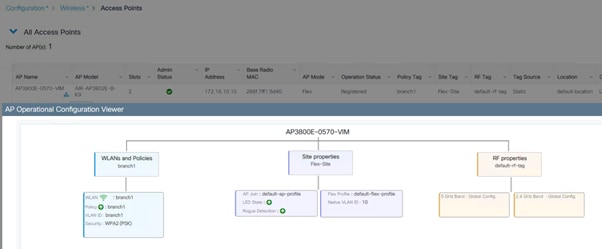
This will show you if the SSID is being broadcasted or not (it will be gray and not green). The ![]() icon will turn red if there is a tag misconfiguration.
icon will turn red if there is a tag misconfiguration.
On the CLI, use the show ap tag summary command:

This command clearly indicates whether there is a misconfiguration involving tags and profiles. A typical example of tag misconfiguration is assigning the same WLAN to two different Policy profiles with different Application Visibility and Control (AVC) settings. In this case the show avc status wlan-name command will flag it as an error, with a related explanation.
Notice the Tag Source field in the output of the command above; this tells you how the AP got the tags. The possible sources, in order of priority, are:
● Static: You select the AP and assigns it specific tags. The configuration is saved on the controller based on the AP’s Ethernet MAC address. When an AP joins that specific controller, it will always be assigned the specified tags.
● Location: This is a configuration construct internal to the C9800 (it’s not the AP location that you can configure on each AP), and it’s used primarily in the Basic Setup flow. A location allows you to create a group of three tags (policy, site, and RF) and assign APs to it.
● Filter: You can use a regex expression to assign tags to APs as they join the controller. As of today you can set a filter based only on AP name, so this method cannot be used for out-of-the-box APs. You can also leverage AP Priming profiles (described later in the document in section “Configure predictive join: Primary/Secondary/Tertiary controller”) in the same filter to assign primary/secondary and tertiary controllers.
● AP: The AP itself carries the tag info learned through Plug and Play (PnP) or pushed from the controller
● Default: This is the default tag source.
The first two sources (static and location) are static mapping configurations to assign APs to tags and hence have the highest priorities. The filter allow you to define a dynamic mapping of APs to tags based on regex expressions. When the source is the AP, it means that this information is saved on the AP itself and will be presented to the controller when the AP joins. Finally, if there is no tag mapping configuration on the C9800, and if the APs doesn’t carry any tag information, the AP is assigned the default tags.
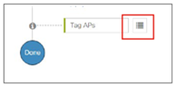
A simple way to assign multiple APs to a set of tags is to use the Advanced setup in the GUI ([Configuration] > [Wireless Setup] > [Advanced]); click Start Now on the main page and then go to the Apply section and click the icon to display the AP list:
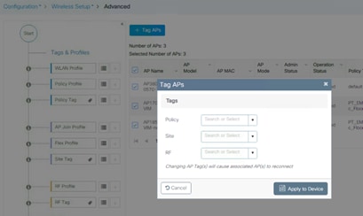
On the following page, select the APs you want and click + Tag APs, then assign the tags in the popup window:
Starting software release 17.6, the tags can be automatically saved on AP leveraging the “AP tag persistency” feature. This is enabled globally on the controller with the CLI command:
C9800(config)#ap tag persistency enable
In 17.6+ the feature is disabled by default for backward compatibility with previous releases, but Cisco recommends enabling it. When the tag persistency feature is enabled, APs joining a C9800 wireless controller will have the configured tags saved on the AP automatically.
Before AP tag persistency was introduced, to push and save the tags to the AP, you had to use a CLI command in exec mode, per single AP:
C9800#ap name <APname> write tag-config
The operational advantages of AP tag persistency feature are clear when you need to move APs between wireless controllers. This can be in the context of APs migration or in a primary/secondary (N+1) high availability deployment. Since the tags are saved on the AP, when the AP joins the second WLC, it will present the tags and as long as these exist on the controller, the mapping will be honored. Of course, the tag source priorities still apply, and the AP tag source is considered only if no static or filter-based mapping are present for that AP.
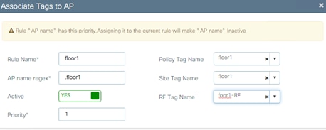
Another way to preserve tags when moving APs from one controller to the other is to use an AP tag filter. Let’s say you want to move APs that are on floor 1 from WLC1 to WLC2. Let’s assume that you have named the AP accordingly as “APx_floor1,” where “x” is the AP number. You need to configure the desired tags on both controllers and then, on WLC2, configure a filter rule to match any AP name that ends with “floor1” and assign it to the desired tags. Go to Configuration > Tags & Profiles > Tags, and click Filter:
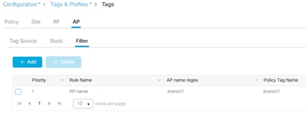
You can add a new rule by clicking +Add in the page above. Here is an example of a rule that matches any AP name ending with floor1:
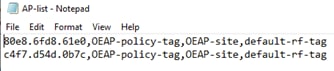
Finally, you can ensure the AP is assigned the right tags when joining another controller by pre-configuring the AP to tag mapping using a CSV file. This is easily done in two steps:
● Create the CSV file first. It needs to be in a specific format: “AP Ethernet MAC, Policy Tag name, Site tag name, RF tag name”. Here is an example:
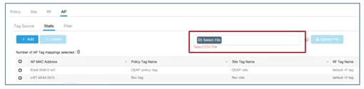
● Load the CSV file in Configuration>Tags & Profiles>Tags as indicated in the following screenshot:
Since you can modify the existing tags, create new ones, and attach them to the APs in different ways, it’s recommended that you validate the tag configuration using the following command in exec mode to catch any inconsistencies:
C9800#wireless config validate
Moving APs between controllers and preserving tags
The previous paragraph describes how the C9800 handles the mapping of tags to APs. Given this information, the following should be considered when moving APs between two C9800 wireless controllers (C9800-1 and C9800-2):
● If the AP on C9800-1 doesn’t hold any tag information (either via the ap tag persistency feature or via the command ap name <APname> write tag-config) and there is no mapping configured for that AP on C9800-2, the AP will be assigned default tags when moved to C9800-2.
● The AP will retain the tag information when moving between the controllers, if both have the same mapping of AP to tags. This can be done via static configuration, by assigning the AP to a location, or via tag filters.
● The AP will also retain its tags when moved between the two controllers if the tags are saved to the AP itself (either via the ap tag persistency feature or via the command ap name <APname> write tag-config), the tags are defined on both controllers, and there is no higher priority mapping defined (i.e., the AP is assigned another set of tags on C9800-2 via static configuration).
● If the AP has saved tags and joins a controller where those tags are not defined, it will be assigned to the default tags (assuming no other mapping is configured on the controller that the AP is joining).
● In all cases, if the AP retains its tag name assignment but the settings within the tag are different on the two controllers, the AP will be configured based on the settings present on the currently joined controller.
Note: The above information applies to N+1 redundancy as well.
When moving an AP from an AireOS controller to a C9800 controller, since the AP doesn’t carry any tag information from AireOS, it will be mapped to the default tags; this is true unless a static or dynamic tag preassignment has been done on the C9800 controller, as explained above.
Policy tags are used to decide which SSID is being broadcasted by which AP and with what policy, so they define the broadcast domain for a group of APs. In this, the policy tag is very similar to the concept of AP group in AireOS.
By default, a client roaming between two APs configured with the same SSID, but different associated policies will result in a slow roam. In other words, roaming across two different policy tags (same SSID, but different policy profile name) will force client to go through a full authentication and DHCP process to renew its IP address. This is true even if doing intra-controller roaming, and it is meant to prevent clients from jumping from one policy to another without a full reauthentication.
Note: If the policy profile associated to the SSID is the same (same name and content) in different policy tags, then roaming for that SSID is seamless. The slow roam happens if there is a change in the policy profile associated to the SSID.
This needs to be considered when designing your wireless network with the C9800. Consider a customer use case in which a university has a rule to use /22 subnets across the campus. It uses one network-wide faculty SSID, and since it has more than 1022 users, it needs to assign multiple client subnets to the SSID.
In AireOS, there are three common ways of implementing this:
1. Using a VLAN override from the AAA server to assign different groups of users to different subnet/VLANs.
2. Using VLAN Select (a.k.a. the interface group feature) to map multiple client subnets to the same SSID and assign clients in a round-robin fashion to the available VLANs in the group.
3. Using AP groups to map a specific VLAN to the SSID for each group of APs. This also allows the user to know deterministically which IP subnet the client will belong to as it joins that location (group of APs).
Option 1 is fully supported with the C9800. You can also use option 2 by using a feature similar to AireOS’s VLAN Select, which is called VLAN groups. Recall that the Cisco Catalyst wireless controller doesn’t need a Layer 3 interface associated to the client VLAN, so you can group the Layer 2 VLANs.
Note: If a client has static IPs and you are using VLAN groups, you must have an SVI configured to each VLAN in the VLAN group, otherwise the client will be excluded. More information in https://www.cisco.com/c/en/us/td/docs/wireless/controller/9800/17-15/config-guide/b_wl_17_15_cg/m_conf_vlan_grp_vewlc.html#vlan-grp-supp-dhcp-stat-ip-cl
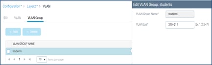
Configure the VLAN group first and assign the VLANs (VLANs 210 and 211 in this example):
Then configure the Policy profile to map the SSID to the defined VLAN group:
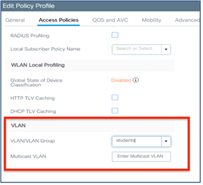
And then assign all the APs to the same policy tag where the SSID is mapped to this policy.
For option 3, you would have to define two Policy profiles, one with VLAN 210 and one with VLAN 211, and map them to the same SSID using a different policy tag. Then you apply the different policy tags to the different groups of APs. In this case, you need to consider the limitation of slow roam across policy tags mentioned earlier: if the two locations are separated and have an air gap, there is no problem, as the client will have to disconnect anyway. But if the locations are in the same roaming domain, you need to consider that the client will go through a full reauthorization as it roams across the two policy tags with different VLANs. This is different from AireOS behavior: An AireOS WLC would allow seamless roaming across two AP groups mapped to different VLANs.
Starting with Cisco IOS XE Release 17.3, if the policy profiles differ only for certain parameters (VLAN and ACL being the most important), then seamless roaming is allowed across policy profiles (and related policy tags). To configure the feature, enter the following command in global config mode:
C9800(config)#wireless client vlan-persistant
Even if the command only mentions “VLAN”, in reality there are many other parameters that can differ between the two policy profiles and still result in a seamless roam. For a complete list of these attributes, visit: https://www.cisco.com/c/en/us/td/docs/wireless/controller/9800/17-15/config-guide/b_wl_17_15_cg/m_client_roaming_policy_profile.html.
The recommendation is to consider this behavior as you design your policy tag assignment: All APs in the same roaming domain should have the same policy profile; if you need to assign different policies, then we recommend you deploy release 17.3 and newer and use the wireless client vlan-persistant feature.
Designing for large scale deployments
With the high-end model, Catalyst 9800 Wireless LAN Controller supports up to six thousand APs and 64k clients on one single platform; this is a lot of APs and clients. When dealing with large, high-density deployments, you may want to make sure that you keep the load of your WLC under control.
Note: For more details on how to design for high client density, see the Wireless High Client Density Design Guide: https://www.cisco.com/c/en/us/td/docs/wireless/controller/technotes/8-7/b_wireless_high_client_density_design_guide.html and https://www.cisco.com/c/en/us/support/docs/wireless/catalyst-9800-series-wireless-controllers/222000-design-guide-cx-wireless-for-large-pub.html
Most of the time, when you hear the word “load” this refers to the CPU load. Catalyst 9800 physical appliances have data plane acceleration in hardware, so what may stress the multi-CPU software architecture is mostly the control plane related activity: handling AP CAPWAP messages, client onboarding, client roaming, rogue management, interference detection, client CPU intense applications like mDNS, and so on.
The system load totally depends on the specific type of deployment and scaling factors, for example: number of APs, density of clients, client authentication and roam rate, client roaming type, key caching mechanisms, applications being used, these are all factors that would impact the system capacity; it is hard to provide upfront a recommended scale number for your specific deployment.
Even if it’s difficult to estimate in advance what would be the load on your network, in system design it is good practice not to utilize a single box to its maximum capacity, but instead to leave some head room to handle “rainy days” situations and peaks of utilization.
C9800 design is no different and, generally, Cisco recommends limiting the load to around 80% of the AP and client scale.
The 80% scale is just a recommendation to start planning the design and deployment of a catalyst wireless network as this is tested and validated number.
For C9800-80/CW9800H1/H2, for example, this means 4800 APs and/or around 50k clients. Does this mean that you cannot have six thousand APs on a single C9800-80? No, not really; Cisco has a lot of successful deployments at maximum scale. The 80% scale is just a recommendation to start planning the design and deployment of a catalyst wireless network.
The opposite is also not true: you can stress a C9800 multi-cpu system with a much smaller number of APs and clients in certain situations. High CPU issues are not always due to product scale and performance limitations; instead, there are multiple factors to consider like client probing and roaming behavior, client applications behavior, nature of the client traffic and many more. Wi-Fi being an evolving and growing technology, client traffic is getting scaled vertically and horizontally. It’s always best to cater for anticipated changes and have your system capacity optimized to get head room to handle situation when there is spike in utilization.
It is important then to monitor the CPU load of the processes and make sure your system operates under the recommended load: if the CPU is < 70% for 5 mins, then you are good; CPU spikes (under a minute of duration) to 80/90% are absolutely normal.
You can monitor the internal processes with the CLI command:
show processes cpu platform sorted | inc Name|---|wncd
or directly on the main Dashboard page, under CPU & Memory Pressure Graph dashlet:
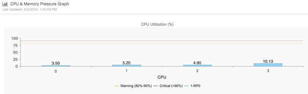
If your CPU load is constantly higher than 70%, then you may start looking deeper and find ways to optimize the use of the resources on the box. A good starting point would be to look at your site tag design, as explained in the next section. These 2 documents provide detailed troubleshooting steps:
● Troubleshoot Wireless LAN Controller CPU Load: https://www.cisco.com/c/en/us/support/docs/wireless/catalyst-9800-series-wireless-controllers/221965-troubleshoot-wireless-lan-controller-cpu.html
● Understand High CPU Usage Reported for the Dataplane on Catalyst 9800: https://www.cisco.com/c/en/us/support/docs/wireless/catalyst-9800-cl-wireless-controller-cloud/221058-understand-high-cpu-usage-reported-for-t.html
Designing with site tags in mind - Local mode APs
Catalyst 9800 Wireless LAN Controller is based on IOS XE multi-process architecture.
There is a process dedicated to the most crucial functions: Mobility and Roaming, Radio Resource Management (RRM), Rogue Management, etc. The main process responsible for AP and client sessions is called Wireless Network Controller processes (WNCd); the number of internal WNCd processes varies from platform to platform as you can see in this table:
Table 1. Number of WNCd processes per platform
| Platform |
WNCd Instances |
| EWC (on AP and Catalyst 9k switches) |
1 |
| C9800-L |
1 |
| C9800-CL (small) |
1 |
| C9800-CL (medium) |
3 |
| C9800-40, CW9800M |
5 |
| C9800-CL (large) |
7 |
| C9800-80, CW9800H1, CW9800H2 |
8 |
You can verify the number of WNCd in your platform using the following CLI command:
C9800#sh processes platform | inc wncd
This is different from AireOS-based WLC, where you had only a single, multi-thread process handling not only AP and client sessions, but all the WLC functions. The advantages of the C9800 multi-process software architecture are multiple:
● Each process is single threaded, non-blocking
● There is no single fault domain (e.g. memory separation)
● Data separation & data externalization per process
● Easier to scale horizontally by adding multiple WNCd
● Process patchability
This software architecture has allowed Cisco to introduce important innovations for Catalyst Wireless like In-Service Software Upgrade (ISSU), Software Maintenance Updates (SMU) and many more.
Having a multi-process software architecture means that to best utilize the platform, you would need to make sure that all processes are equally used. Since WNCd handles all the AP and related client sessions, it’s clearly a good starting point and you want to make sure that the AP load is balanced across the different internal processes.
When APs join the C9800, they are distributed among the available WNCds (of course, this applies to the platforms where multiple processes are present). As you can imagine, load balancing APs (and the related clients) among the available WNCd processes, result in improved scale and performances as it better exploits the available resources on the C9800.
AP distribution among the internal processes is based on site tags: APs associated with the same site tag join and hence are managed by the same process. The AP mapping is done on the first AP that joins from a specific site tag.
As you design your Cisco Catalyst Wireless network for best performances, it becomes important to understand how to assign APs to site tags and hence to internal processes. Let us start with some general recommendations that you need to keep in mind as you deploy Catalyst 9800 wireless controller with local mode APs (some specific FlexConnect recommendations are highlighted in a later section):
Use custom site tags and not the default-site-tag, especially when roaming and fast roaming is a requirement.
1. Assign the same site tag to all the APs in the same roaming domain. Roaming domain is defined as a logical group of APs that share the same RF domain and broadcast the same SSID.
2. Limit the number of APs you assign to a single site tag (a value of 500 APs per site tag is recommended).
3. Whenever possible, do not exceed the following maximum number of access points per single site tag as per table below:
Table 2. Access Points per single site tag
| Platform |
Maximum number of APs per site tag* |
| C9800-80, CW9800H1, CW9800H2, C9800-CL (medium and large) |
1600 |
| C9800-40, CW9800M |
800 |
| Any other C9800 platform |
Maximum number of APs supported |
*These numbers are for local mode APs. For FlexConnect APs and related remote site tags, if seamless roaming is required, the limit is 100 APs per site tag. As of release 17.8.1, the limit has been increased to 300 APs per site tag leveraging the “Pairwise Master Key (PMK) propagate” feature, also called “FlexConnect High Scale Mode”.
4. If dealing with large deployments, high density scenarios, it’s recommended to use a number of site tags equal the number of WNCD processes for that specific platform and evenly distribute APs among these. If you have more site tags for whatever reason, it’s recommended to keep it as a multiple of the number of WNCDs (e.g., site tags = 5,10,15, etc. for the 9800-40) and still distribute the APs evenly.
Note: The recommendations above are just that: recommendations. For example, if you have more than 500 APs in the same site tag, things will still work but you would probably not get the best performance out of your network.
The first recommendation tells you not to use the default-site-tag and helps improving the way the resources are used internally on the C9800, optimizing for intra-process vs. inter-process communication. By using custom site tags, all the APs that belong to the same site tag will be assigned to the same internal process.
By making the roaming domain match the site tag, as mentioned in the second recommendation, you make sure that most roaming happens within the same process. If using the default-site-tag, the APs would be distributed among the available processes in a round robin fashion, increasing the chances of inter-process communications when clients roam from one AP to the other.
Before release 17.6, assigning the same site tag to all the APs in the same roaming domain is also particularly important if you require optimized fast roaming for applications that are delay sensitive, such as voice over WLAN (Wireless LAN). “Optimized” here means that C9800 would leverage protocols such as 80211k/v to pass additional information to the client and assist the roaming process; for example, the list of neighbor APs the client could roam to, is provided via 802.11k neighbor list. When roaming between two APs in different site tags, and hence across WNCd processes, the AP neighbor information was lost, and hence protocols such as 802.11v and 802.11k that rely on this information are not optimized. This is another reason to assign all the APs in the same roaming domain (where seamless and fast roaming is needed) to the same site tag. This affects only 802.11k/v and doesn’t affect fast and seamless roaming, which is supported across site tags.
Important: This limitation is removed starting release 17.6.1, so clients roaming across site tags can benefit from 802.11k/v. In this release the user will have to manually check if the SSID is enabled on the neighboring APs by making sure that it’s included in the policy tag. Starting release 17.7.1, the check is automatic.
Note: Talking about roaming support, for APs in local mode (so SSIDs with central association), seamless roaming with 802.11r and opportunistic key caching (OKC) works across site tags. No limits.
Why not assign all the APs in one single site tag and get over with it? Here is where the third suggestion comes into the picture: For the best performance you should limit the number of APs per site tag and hence per WNCd. By having multiple site tags and limiting the number of APs per site tag, you reduce the chances of overloading a single process. The number Cisco recommends is around 500 APs per site tag. This is just a reference number that can be used for all the different Catalyst 9800 platforms.
Let us be clear: Nothing will break if you assign more than 500 APs per site tag, if you stay within the limits that have been tested and hence officially supported and that are specified in the table shown above.
Note: 500 AP is also the default maximum number of APs that Cisco Catalyst Center would place in a single site tag. Starting release 2.2.2, the user can configure custom site tags in Cisco Catalyst Center and hence design according to the specific deployment.
Going beyond those maximum limits (e.g., 800 APs per site tag in a 9800-40) is not recommended and you will start seeing some undesired performance effects: the client roaming per second may decrease, same for the authentication per second. Customer may also see syslog events indicating an overload in a WNCd process. These are all effects of the overloading of a single WNCd process. Imagine if C9800 was a car’s engine and the WNCd processes its cylinders: if you drive your car with just one cylinder, the results will not be great and optimized, right?
What if you have a large deployment (large hospital, conference center, stadium, big enterprise campus, etc.) which is one big roaming domain? How do you design your site tags? How would you distribute the APs among multiple custom site tags?
First, let’s clarify one important concept: the site tag does not have to coincide with a geographical physical site, even if the name would suggest that. The site tag is a logical group of access points that allows you to assign certain common settings (the ones contained in the AP join profile). It’s also used internally to optimize the processing of AP and client events related to that group of APs.
For a high-density (HD) deployment, where you have a lot of clients, and these clients can roam seamlessly everywhere, in order to optimize the performance of C9800, it’s recommended that you choose the number of site tags according to the specific platform, as listed in the table below:
Table 3. Recommended number of site tags for high density single site deployments
| Platform |
Recommended number of site tags |
| C9800-80, CW9800H1, CW9800H2 |
8 |
| C9800-CL (large) |
7 |
| C9800-40, CW9800M |
5 |
| C9800-CL (medium) |
3 |
Once you have selected the number of custom tags, you also need to evenly distribute APs across these site tags. Again, remember that the site tag doesn’t have to correspond to a physical site, but you would have to create virtual areas where you group APs.
Here are some examples to understand how we can implement these recommendations:
● You need to design a large venue (i.e., a stadium) with 3000 APs and 10s of thousands of clients. Roaming is required everywhere, so this is indeed a large roaming domain. You have selected a C9800-80 to manage this deployment. The recommendation is to identify eight virtual roaming areas (grouping sectors in the stadium, for example) where you know that most roaming will happen and define a site tag for each one. In this case it’s 3000 APs across eight site tags, it would be 375 APs per site tag. Of course, it does not have to be a precise cut, but the recommendation is to have an equal distribution of APs, and avoid overloading few site tags, even if it would make sense from a physical location/site point of view. On the other side, if you have small areas (e.g., the ticketing areas) where you have few APs, merge them with other APs to get to a site tag size that is close to the recommended one, 375 APs in this case.
● You have a small campus with three buildings with 600 APs on a C9800-40. Most of the time there would be no Wi-Fi coverage (air gap) between the buildings and there is no roaming across; in this case you can configure three site tags, one per building. This means 200 APs per site tag which is well within the recommended settings.
● You have a large campus and multiple buildings for 1200 APs on a C9800-40, and this time roaming must be across the entire campus (i.e., Hospital campus). Since 1200 exceeds the maximum number of APs per site tag, and this a large roaming domain, it is recommended that you use five site tags (grouping buildings together in five virtual areas). In this case you would have an exceptionally good balanced system with 240 APs per site tag. Remember: seamless roaming is fully supported across the site tags; from 17.7 also 802.11k/v works across site tags.
Designing with site tags in mind - FlexConnect mode APs
For FlexConnect deployments, site tag identifies the fast-roaming domain as client key caching and key distribution only happens within a single Flex site-tag. Normally and naturally, you would have a site tag for each remote location where fast roaming is required, so the chances of overloading a single internal process for FlexConnect deployments are much smaller than for local mode.
Here are the FlexConnect specific recommendations when it comes to design your site tags:
● The default-site-tag is a no-go for Flex deployments where fast roaming is a requirement and hence the use of custom site tags are always recommended. Reasons being that the client key is not distributed among the FlexConnect APs in default-site-tag. You should configure at least one site-tag per Flex site.
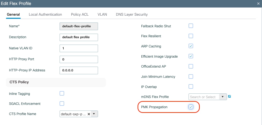
● If support for Fast Seamless Roaming (802.11r, CCKM, OKC) is needed, then the max number of APs per site-tag for a Flex site is 100 (the same as for AireOS). As of release 17.8.1, the limit has been increased to 300 APs per site tag leveraging the “Pairwise Master Key (PMK) propagate” feature, which is disabled by default.
This can be configured under the FlexConnect profile with the following command:
C9800(config)#wireless profile flex NAME
C9800(config-wireless-flex-profile)#pmk propagate
Or alternatively in the GUI:
● Don't use the same site tag name across multiple FlexConnect sites (this includes the default-site-tag). The C9800 doesn’t know about your physical locations and there is no point in distributing client keys across APs in different physical locations as roaming will never happen. Also, different site tag names are a requirement to support client overlapping IP addresses across Flex connect sites for local switching SSIDs.
● In order to save WAN bandwidth and make the software download more efficient for APs in remote sites, efficient upgrade is on by default under the FlexConnect Profile. For each site tag with FlexConnect APs, one AP per model is selected as the master AP and downloads the image from the WLC through the WAN link. Once the master AP has the downloaded image, the APs in that site tag start downloading it from the master AP. By mindful of site-tag assignment, if a site-tag is spanned across more than one branch APs might be downloading the image from another branch instead of the WLC.
One last but important consideration about site tag design. What if you are forced to have a mix of large and small size site tags and you cannot distribute the APs evenly as recommended? This would be the case where you have a deployment with a campus (with Local mode APs) and many small remote sites (with FlexConnect APs). As explained earlier, for FlexConnect every site should be its own site tag, as it defines the fast secure roaming domain, so you don’t have much choice around the number of tags; In this case, to have the best load balanced system and follow the recommendations for local mode APs, it’s probably best to have two WLCs, one to manage the campus APs and a different one dedicated to the branches, maybe using a 9800-CL to optimize costs.
Enhance your design with the site-tag “load” command
In the previous sections, you have learnt the best practices around designing your site tags to optimize the resources on Catalyst 9800. This can create an operational burden on the IT team, as the definition of the number of site tags, identifying which APs must be mapped to which tag and then implementing the configuration, may require planning and time.
Starting 17.9.2, a new “load” command under the site tag configuration has been introduced, to help further optimize your site tag-based design and simplify your IT operations. This command indicates the controller what to expect in terms of load. One could use the AP count as the load, or it could also represent the number of clients or utilization, it is up to the user.
Prior to this enhancement, the C9800 had no indication about the size of the site tag and the AP to internal processes load balancing decisions were made only considering the number of site tags and not the actual number of APs and hence the load they could generate. The system still works well if the APs are evenly distributed across the site tags, as recommended in the previous sections.
However, in case where you have site tags of disparate sizes and if the number of the site tags is greater than the number of WNCd processes, it is possible to end up with an unbalanced systems configuration where some processes are heavily loaded, and others are underutilized.
The Enhanced Site Tag-Based Load Balancing feature allows you to configure a site load, thus allowing the system to take better load balancing decisions. The load is configured under the site tag using the following CLI:
C9800(config)#wireless tag site <name>
C9800(config-site-tag)#load <1-1000>
It is recommended to reboot the WLC after configuring the load and after all your site tags are active, meaning they have at least an AP joined. The behavior of the load balancing feature in the controller reboot case is as follows:
● After you have configured the feature and rebooted the controller, even before any APs join, the load balancing feature retains the site tags that are used actively in persistent memory and load balances them during bootup. The load balancing during bootup occurs in descending order of the configured site load.
● After you have configured the load balancing feature in a site tag with APs already joined, the load balancing remains unchanged unless all APs, including those not in the site tag, disconnects or the controller reboots.
How to choose the value for the load parameter? Load is an estimate of the relative WNCd capacity reserved for that site tag and hence group of APs and related clients.
All control plane activities contribute to the “load” of the internal processes: client probing, client joining, client authentication, roaming, but also features like mDNS that require CPU time. The busier the AP, the bigger the “load”. The most common option would be to set the load equal to the number of APs in the site tag. This a good option with office buildings where you estimate that each AP would have a similar number of clients and hence activity.
If you have a building/area/floor with a higher expected activity (e.g., lot of clients joining, leaving and roaming) like in a conference/training center, cafeteria, then set a higher weighted “load” for that specific site tag. For instance, if 10 APs are present at the conference center area, configure the load to be 20.
Requirements and recommendations:
● It makes sense to use the load only if the number of site tags configured is greater than the number of WNCd processes.
● All the site tags need to have the load configured.
● Configuring the load is recommended for both Local and FlexConnect mode deployments.
● The configured load is only an estimate. It will only be used for site tag load balancing. Specifically, it does not prevent APs, or clients from joining or associating.
● How to choose the load? For sites with normal client density, you can use AP count as a good approximate of the site load. Examples of such sites are office floors and buildings. For sites with high client density and roaming load, you can use a higher load configuration than the number of APs. For example, if the number of APs in such a site is 200, you can use a load factor of 300 or 400 to compensate for higher client load. Examples of such sites include cafeterias, auditoriums, conference centers floors, etc.
● For the AP distribution algorithm to take into consideration the load, and be independent of AP joining order, configure the load parameter under the site tags and reboot the C9800
For a site tag to be considered for load balancing, it needs to have at least one joined AP. This information is saved and remembered by the system for subsequent runs.
If you have a new installation, since AP join times can vary, the system waits for an hour from its last boot, for APs to come up before saving the active tags and consider those in the calculation. This is the reason why the WLC reboot should be triggered after at least one hour of uptime.
If the C9800 is not rebooted, the load balance algorithm is still improved as it takes into consideration the site load with the configured load parameter; but it’s going to be dependent on the order of AP joining the WLC.
Enhance your design with the RF based Automatic AP Load Balancing
Starting release 17.12, the RF based Automatic AP Load Balancing feature may improve the existing site tag-based load balancing described in the previous sections. Unless properly planned, the site tag-based method may lead to uneven distribution of APs across the internal instances, which in turn may result in higher memory and CPU usage. Though enhanced by the load command, the site tag-based method may still lead to suboptimal performances if the AP load limit is not correctly configured, or the customer has decided to put most of the APs in one large site tag.
The RF based Automatic AP Load Balancing feature uses Radio Resource Management (RRM) to automatically group APs and load-balancing across WNCd instances. When this feature is enabled, it forms AP clusters based on the RSSI received from AP neighbor reports. These AP clusters or neighborhoods are further split into sub-neighborhoods and smaller areas. The resulting groups of APs are then distributed evenly across the internal processes.
The RF based Automatic AP Load Balancing is a 2-step process: running the algorithm (also known as learning) and then applying the algorithm. Running the algorithm can be on-demand or scheduled. The algorithm is applied automatically after a controller reboot or manually through an AP CAPWAP reset triggered by the ap neighborhood load-balance apply command. When the RF based Automatic AP Load Balancing feature is active, it overrides other site tag-based load balancing.
For enabling and configuring RF based Automatic AP Load Balancing, please refer to the configuration guide: https://www.cisco.com/c/en/us/td/docs/wireless/controller/9800/17-15/config-guide/b_wl_17_15_cg/m_auto-wncd-lb.html
Requirements and recommendations:
● This feature is recommended for better load balancing when the number of site tags is greater than the number of WNCD for that specific platform or when site tags have more than a 100 APs.
● This feature is supported only on APs in Local, Fabric and FlexConnect mode.
● For a new deployment, it is still recommended to use the site tag-based method and follow the recommendations to evenly distribute the APs, together with the site tag load command. Why? Using site tags, you can ensure that all the APs of the same site tag go to the same WNCd, which helps in troubleshooting and optimizes for intra-WNCd roaming.
● For a new or existing deployment, if you are unable design around site tags because you cannot group APs (for example: APs don’t have a representative name and/or you don't know where they are located), or you do not want to spend time designing site tags, then you can use the default site tag or any named site tag and turn on the RF based Automatic AP Load Balancing feature. Keep in mind that you may have performance impact when compared to an evenly load balanced system using site tags and load.
● In an existing deployment, if you have high CPU issues because of an unbalanced system, use the auto RRM load balance system instead of redesigning the site tags.
● Remember the golden rule: if you do not have any CPU load issues despite having an unbalanced system, do not change anything.
● The RF Auto Load Balancing works best when there are a 100 or more APs per site, for deployments with small site tags it is better to use the load command instead as explained in the previous section.
● Remember that using this feature is a 2-step process, learning and applying, see the configuration guide.
● It’s not recommended to turn on this feature when the overall load on the system is high.
The previous sections covered the different types of AP load balancing support on the Cisco Catalyst 9800 Wireless LAN Controller. This section provides a summary of the load balancing mechanisms discussed thus far.
Table 4. AP load balancing summary
| Load balance mode |
Configuration recommendation |
Remarks |
| None |
If the WNCd is always low, there’s no need to do anything! |
|
| Load-Based Site Tag |
Used in cases where site tags are of disparate sizes and the number of site tags exceeds the number of WNCd processes. |
The controller needs to be rebooted once the load-based site tag configuration is enabled |
| RF based Automatic AP Load Balancing |
Recommended when there are a lot of small site-tags and less than a 100 APs per site tag. |
Suitable for deployments where the administrator does not want to spend time designing site tags. This approach provides less granularity, as RRM assumes ownership of site tags. Remember that this is a 2-step process, learning and applying. |
General C9800 Wireless Controller settings
These settings apply to the C9800 wireless controller at a box level.
There are two ways in which you can run a Cisco IOS XE image on a C9800 WLC:
● Install mode: The install mode uses pre-extracted files from the binary file into the flash in order to boot the controller. The controller uses the packages.conf file that was created during the extraction as a boot variable. Install mode is the default mode.
● Bundle mode: The system works in bundle mode if the controller boots with the binary image (.bin) as a boot variable. In this mode the controller extracts the .bin file into the RAM and runs from there. This mode uses more memory than install mode, since the packages extracted during bootup are copied to the RAM.
You can check the mode using this show command:
9800#show version | i Installation mode
Installation mode is INSTALL
Note: Install mode is the recommended mode to run the Cisco Catalyst 9800 Series wireless controller because it provides the following advantages: support for high-availability features like In-Service Software Upgrade (ISSU), software maintenance upgrade (SMU)/patching (hot and cold), faster boot time, less memory consumption, and Cisco Catalyst Center support for upgrades.
If for some reason the box is in bundle mode, follow these steps to boot in install mode:
Check if you have enough space in flash to download an image:
C9800#dir flash:
1. Clean up old installation files that are not used, to free up space:
C9800#install remove inactive
2. Copy the image to flash, for example, using the TFTP transfer.
C9800#copy tftp://<path> flash:
3. Delete the current boot variable and set it to point to packages.conf. Use the following commands:
C9800(config)#no boot system
C9800(config)#do write
C9800(config)#boot system bootflash:packages.conf
C9800(config)#do write
4. Install the image to flash and then activate and commit the code. This moves the C9800 from bundle mode to install mode. You can do this in one command:
C9800#install add file bootflash:<image.bin> activate commit
There is only one wireless management interface (WMI) on the C9800, and this is a Layer 3 interface. The WMI terminates all the CAPWAP traffic from APs and is the default source interface for all the control plane traffic generated from the box. It is recommended that you use a Switched VLAN Interface (SVI) as the WMI for all deployments, including Foreign -Anchor for guest traffic. The only exceptions would be for C9800-CL in a public cloud, where it is mandatory to use a Layer 3 port for wireless management; and for the embedded wireless in Cisco Catalyst 9000 switches, where a loopback interface is recommended.
Note: The C9800 doesn’t have multiple AP Manager interfaces, as AireOS does. It uses only one interface for CAPWAP termination: the WMI.
Support for jumbo frames and the “ip mtu” interface command
Jumbo frames are Ethernet frames with payloads larger than the standard 1500 bytes limit, commonly up to 9000 bytes. To change the maximum transmission unit (MTU) of the packets sent by C9800/CW9800, you can use the “mtu” and the “ip mtu” command under a Layer 3 interface (SVI):
C9800(config)#interface vlan 105
C9800(config-if)#mtu ?
<1500-9216> MTU size in bytes
C9800(config-if)#mtu 9100
C9800(config-if)#ip mtu 9000
IP MTU command changes the payload size of the IP packet while the MTU command changes the payload of the Ethernet frame. The default value is 1500 bytes for both. In order to change the IP MTU to something bigger than 1500 bytes, you need first to increase the L2 payload.
There are two types of traffic on the C9800/CW9800:
1. Traffic originated from the box itself: Radius, Syslog, SNMP, etc. - supported
2. Client traffic via CAPWAP – NOT supported
For the traffic originated from the box (type 1 above), starting 17.11, Cisco supports changing the MTU of the packets. For Radius packets specifically, you also need to specify the radius source interface, where you want the IP MTU change to be applied, in the aaa group server configuration section. More details here: https://www.cisco.com/c/en/us/support/docs/wireless/catalyst-9800-series-wireless-controllers/222920-understand-radius-mtu-and-fragmentation.html
At the time of writing, changing the MTU for the client traffic and hence for CAPWAP packets is not supported. This means that jumbo frames for client traffic and CAPWAP is not supported.
Of course, the APs do a dynamic Path MTU Discovery (PMTU) when joining the WLC to find the best MTU to use when sending a packet. IP MTU cannot exceed 1500 bytes, it can be smaller. This smaller MTU is usually useful where CAPWAP traffic needs to traverse a WAN network, and MTU needs to be lower than 1500 due to multiple encapsulations.
Configuration requiring controller reload or network down
Thanks to the software architecture of the C9800, there are no features that require a box reload to make them effective. This is important for increasing the uptime of the whole wireless network. The only exceptions to this are when changing the licensing level on the box and configuring stateful switchover (SSO) redundancy.
The only functionality that requires a shutdown of the wireless network (in all 3 frequencies, 2.4-GHz, 5-GHz and 6-GHz networks) is mainly the radio resource management (RRM) settings.
Enabling Network Time Protocol (NTP) is very important for several features. NTP synchronization on controllers is mandatory if you use any of these features: Location, Simple Network Management Protocol (SNMP) v3, access point authentication, or 802.11w Protected Management Frame (PMF). NTP is also very important for serviceability.
It is also possible to configure the AP time zone to avoid events having different time stamps. This can be done in the AP Join Profile under general or with the following command:
timezone {use-controller | delta hour offset-hour minute offset-minute}To enable the NTP server via the CLI, use this command:
C9800(config)#ntp server <IP or dns name>
Via the GUI, do the following:
It is possible to specify the source interface for NTP traffic. On the physical appliance, this might be useful to configure NTP to go out of the service port (SP), which is the out-of-band management port. On the 9800 Series physical appliance, the SP is mapped to a separate management Virtual Route Forwarding (VRF) instance (Mgmt-intf ). In order to configure this, use the following CLI command:
ntp server vrf Mgmt-intf <ip or dns name>
The C9800 also supports synchronization with NTP using authentication. To enable NTP authentication, use the following commands:
C9800(config)#ntp authentication-key 1 hmac-sha2-256 <key value>
C9800(config)#ntp authenticate
C9800(config)#ntp trusted-key 1
To confirm that the status of the NTP server is synchronized, use the following command:
C9800#sh ntp status
Clock is synchronized, stratum 9, reference is 172.16.254.254
[…]
For the C9800, all the different form factors have the same base software code. This is important and simplifies customer deployments when there is a mix of physical and virtual appliances. This means that the user interface is the same and the features are the same.
There are two “exceptions” for this, the controller embedded on a switch and the ultra-low 9800-CL. The controller embedded on the Cisco Catalyst 9000 switches supports only Software-Defined Access (SD-Access) architecture, so only the functionalities related to fabric deployment mode will be supported. The ultra-low version of the Cisco Catalyst 9800-CL Wireless Controller for Cloud only supports FlexConnect in local switching mode.
The customer may want to take the configuration from WLC1 and use it on WLC2, performing a “backup and restore” procedure. Here are the recommended steps:
● Copy the configuration from WLC1 to a text file and upload to a TFTP/FTP server
● Copy the configuration file onto the startup-config file of WLC2 using the CLI command copy tftp://<server>/config.txt startup-config.
● Reload the WLC2 box (without saving)
● If password encryption was enabled on the original configuration, before importing the backed configuration the user must configure the password encryption in the new WLC. After doing that, one can import the backed configuration and all keys and passwords will remain intact. Here is the command to configure password encryption:
key config-key password-encrypt <private-key> password encryption aes”
● SNMP v3 users are not part of the configuration file so will not be copied. Add snmpv3 users back using the below command:
snmp-server user <username> <group> v3 auth sha <password> priv aes 128 <password>
● Add the management interface MAC address as wireless mobility mac address as a best practice. Since this is a new instance/hardware, the MAC address of the SVI will change. Use the command:
wireless mobility mac-address
● (get the mac from command show wireless interface summary)
● Add the token for smart licensing “license smart register idtoken
There are extra considerations needed for the 9800-CL as the virtual appliance doesn’t come with a Manufacture Installed Certificate. It needs a Self Signed Certificate (SSC) to terminate CAPWAP tunnel from the AP. Follow the steps below to generate an SSC for a 9800-CL:
● Delete the certificates which were copied along with the configuration. To do this, first check the existing certificates using the command show crypto pki trustpoint
● Delete the existing certificate authority “WLC_CA”: no crypto pki server WLC_CA
● Delete existing device certificates:
no crypto pki trustpoint "<hostname>_WLC_TP"
● Create a new SSC for the management interface using the exec command:
wireless config vwlc-ssc key-size 2048 signature-algo sha256 password 0 <password>
Note: If the customer imported third-party certificates on their Catalyst 9800, it is important to note that the private keys won't be copied by simply copying the configuration. Therefore, the customer will need to import the certificates again on the new WLC. The same is true for the customer’s webauth pages; these would also not be copied this way.
If you are migrating from AireOS WLC to the Catalyst 9800, the configuration file needs to be translated, as the operating systems are different. The Configuration Migration tool is recommended for doing that. A web-based version can be found at:
https://cway.cisco.com/wlc-config-converter/
Note: cisco.com credentials are needed to access the configuration tool.
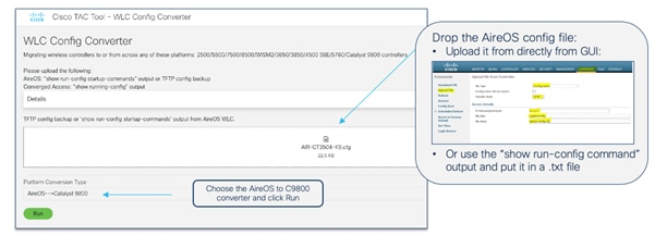
Use the following steps:
● Get the AireOS configuration file, either uploading it via TFTP or using the show run-config commands CLI command, and save it in a text file.
Step 1. Upload the AireOS configuration file to the tool.
Step 2. Select the conversion from AireOS to 9800.
Step 3. Click Run.
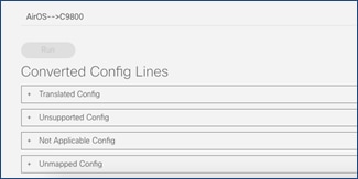
The tool output has four different sections:
Here is a description of each configuration file:
● Translated: Contains the supported CLI commands with the translation from the AireOS CLI to the Cisco IOS XE CLI. This is also useful to see how the same configuration is done on the 9800 Series.
● Unsupported: Contains the CLI commands related to unsupported features (please confirm any unsupported features with your Cisco representative).
● Not Applicable: Contains the list of CLI commands that are not applicable to Cisco IOS XE because things are done differently on the Catalyst 9800 or because the command is deprecated.
● Unmapped: Contains commands related to features that are supported but not yet translated by the tool.
Step 1. Download the translated configuration and edit as needed; you may need to retype passwords for SSID and the RADIUS configuration, and you may need to evaluate the need for SVIs, etc. This file is NOT meant to be blindly copied to the Catalyst 9800.
Step 2. Copy the configuration to the Catalyst 9800 running-config. We recommend you copy and paste directly in the CLI. Alternatively, you can use the CLI tool in WebUI under Administration > Command Line Interface.
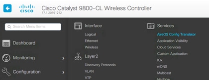
There is also a version of the tool embedded in the C9800 GUI:
The online version at https://cway.cisco.com/wlc-config-converter/ is the recommended one because it is always updated with the latest fixes.
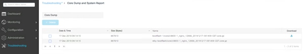
In case of a controller crash, there is enough local storage on the 9800 Series controller to save the file locally, so there is no need to automatically upload it somewhere off-box. In the Troubleshooting section of the C9800 GUI, there is a section where you can easily download the system report file (core dump):
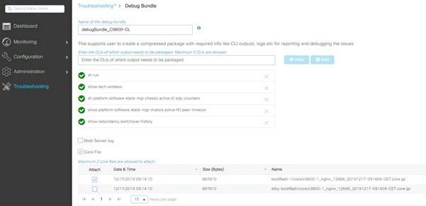
The 9800 Series supports a single file download option to easily collect the most important support data in a simplified way. This will provide a bundle covering crash information, core files, configuration, output of specific CLI commands, etc. It is advisable to always include this file when opening a TAC case, to have a good starting data set.
It’s very easy to access the support bundle from the GUI:
WebUI uses VTY lines for processing HTTP requests. At times, when multiple connections are open, the default number of VTY lines of 15 set by the device might get exhausted. Therefore, it is strongly recommended that you increase the number of VTY lines to 50. Use the following configuration commands to do this:
C9800#config t
C9800(config)#line vty 5-50
Another best practice is to configure the service tcp-keepalives to monitor the TCP connection to the box:
C9800(config)#service tcp-keepalives in
C9800(config)#service tcp-keepalives out
Starting with Release 17.3, it is possible to configure HTTP/HTTPs independently for WebUI access and for redirection for Web Authentication SSIDs. For securing access to the box, it is recommended to disable HTTP for WebUI access. For more information on the configuration options, see the “Configuring HTTP and HTTPS Requests for Web Authentication” section in the Web-Based Authentication chapter in the configuration guide.
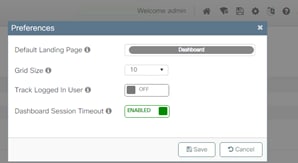
The Dashboard page is a dynamic page, with information being updated automatically. This will prevent the session idle timeout from kicking in and logging the user out (as happens to all other pages). It is recommended that you enable the Dashboard Session Timeout to prevent this. When the dashboard timeout is turned on, then the session idle timeout configured under Administration > Management > HTTP/HTTPS/Netconf/VTY page is in effect. When the dashboard timeout is turned off, the session will expire after 4 hours.
To enable Dashboard session time out, click the settings (gear) icon on the top right corner of any page and toggle this setting:
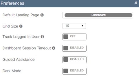
The latest releases include inline guided assistance to help customers with the GUI configuration. The function is embedded into every page in the lower right corner of the screen. Just look for a light blue vertical tab that says, “Guided Assistance” and click on it. If you need to turn it off, you can do so directly from the dashboard preferences (gear icon):
The Cisco Catalyst 9800-CL (CL stands for “cloud”) is the virtual machine form factor that can be deployed on a private or public cloud. There are a few deployment considerations when dealing with the 9800-CL.
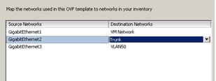
When setting up the 9800-CL on a private cloud, using one of the supported hypervisors, it’s important that, if using multiple interfaces, these are mapped to different virtual networks/VLANs on the virtual switch side:
In the example above, GigabitEthernet1 is mapped to an out-of-band network, GigabitEthernet2 is the main interface for wireless management and client VLANs, so it’s configured as a trunk, and GigbitEthernet3 is used for the redundancy port (RP) and has its dedicated Layer 2 VLAN. If you are not using the port, you should still map it to a dedicated network.
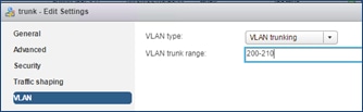
When configuring the trunk, it’s a best practice to make sure that you allow only the VLANs that are in use:
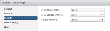
Finally, the security settings: Both Promiscuous mode and Forged Transmits need to be set to Accept on the port group where the 9800-CL is connected. This is needed both for both trunk and nontrunk connections:
These security settings can be restricted to the single port group where the 9800-CL is connected, and as long as the VLANs are available only on this port group, these settings will not affect other VMs connected to other port groups. Please bear in mind that within the port group, setting Promiscuous mode to Accept will result in flooding traffic to all the other VMs on the same VLAN, so it’s recommended that you limit the number of VMs per port group.
Note: The examples above are for ESXi, but the other hypervisors have similar settings and recommendations. Please check the deployment guides for more information.
For the 9800-CL it is recommended that you use the VGA integrated console (the default) and not the serial console.
If you want to shut down the 9800-CL it is recommended that you do it gracefully following this simple procedure:
● Before you power off the VM from the hypervisor, run the exec command reload pause – this command will reload the box and then pause, waiting for the user input to start.
● At this point, go ahead and power off the VM.
Pushing configuration via CLI or GUI may not flash errors to the user if any of the settings are not applied correctly. It is always recommended recommend to check any errors by viewing the logs generated by the box. This can be done via CLI using show logging or checking on the web interface under Troubleshooting > Syslog section.
Configuration: special characters
For any setting that requires the user to configure an open string (AP name, SSID name profiles and tags, etc.), the Catalyst 9800 supports a specific list of characters: these are the printable ASCII characters (ASCII 32-126) without leading or trailing whitespaces. The only exception is for a leading space (ASCII character 32) only in the SSID name. Please also ensure that SSID and AP names do not exceed 32 characters. A list of the printable ASCII character can be found here: https://en.wikipedia.org/wiki/ASCII
Quick tip: what if you need to type the character “?” in the CLI? This special character, for example, could be part of a url that you want to configure in your parameter map; if you try to type this character directly on CLI, you will see that it will not print it (but list available keywords or arguments depending on the mode you are); in this case to enter “?” on CLI, you would use Ctrl+v and then type “?”.
Note: Always ensure that SSID and AP names do not exceed 32 characters.
With Catalyst 9800 Wireless LAN Controller, the focus has been on telemetry. Telemetry works in a "push" model where WLC sends out relevant information to the server without the need to be queried. Catalyst 9800 still offers SNMP for legacy purposes. Some information can be exclusive to telemetry and some of the SNMP object identifiers (OIDs) previously available on AireOS are not yet available on 9800.
For more information on SNMP on C9800 please refer to this link: https://www.cisco.com/c/en/us/support/docs/wireless/catalyst-9800-series-wireless-controllers/217460-monitor-catalyst-9800-wlc-via-snmp-with.html.
If using SNMP to poll different OIDs, the following CLI needs to be configured as a best practice to reduce the possible impact on the C9800 CPU:
C9800config)#snmp-server subagent cache
With this command the cache will be cleared after 60 seconds; to change the interval use the following CLI:
C9800(config)#snmp-server subagent cache timeout ? <1-100> cache timeout interval (default 60 seconds)
Default should be good for most deployments.
The advantage of the Cisco Catalyst 9800 Series configuration model is that most of the recommended settings that are global in AireOS can be configured on a group of APs in Cisco IOS XE using profiles and tags. This gives you the flexibility to decide which APs will get the settings and choose the appropriate values. Let’s look at the recommended settings.
Starting with Wi-Fi 7 Access Points, there is no longer a need to purchase a specific product for a region or country, now there is only one product ID for global use. Also, if for some reason you need to move to a cloud deployment or vice versa these access points can be migrated without any external intervention.
The first step is for the AP to decide if it will join a Catalyst 9800 LAN Controller or the Meraki dashboard. In this document the Catalyst 9800 Controller is covered so we will focus on that. There are several methods of having the AP join the WLC:
● Option 1: where there is internet connectivity from the CW917x series APs and customer having a Meraki Dashboard account. Make the APs join the Meraki Dashboard and migrate the APs to WLC.
● Option 2: Where there is no internet connectivity from the CW917x series APs. Employ discovery mechanisms like DHCP, DNS, Local status page (LSP), Broadcast (IPv4), Multicast (IPv6) or PnP to reach the Catalyst 9800 WLC.
To understand in depth both options please read the Cisco Wireless Global Use Access Points Deployment Guide: https://www.cisco.com/c/en/us/td/docs/wireless/access_point/technical-reference/global-use-ap-dg.html.
When the Global Use AP connects to a Catalyst 9800 Wireless LAN Controller, it must determine the country in which it has to operate to adhere to local RF regulations. The Global Use AP can find the country it has to operate, in multiple ways, see also the Cisco Wireless Global Use Access Points Deployment Guide: https://www.cisco.com/c/en/us/td/docs/wireless/access_point/technical-reference/global-use-ap-dg.html.
Note: For complex scenarios, such as air gapped deployments or similar, where there is no way to obtain GPS/GNSS signal, no legacy APs present in the network and where the APs cannot reach the cloud due to policy restrictions by the organization, the country code can be obtained in a manual way through the Regulatory Activation File (RAF) from the Meraki Dashboard. Even though the RAF file is obtained from the dashboard, there is no need for the APs to reach to the cloud. Please see section Country Code and Regulatory Domain, specifically 6. Regulatory Activation File for more details.
Configure predictive join: Primary/Secondary/Tertiary controller
When configuring access points, always set the primary and secondary (and optionally tertiary) controller names and IP addresses to control the AP selection during the CAPWAP join process. This can prevent APs that are close to each other from joining different controllers (the so called “salt and pepper” scenario) that could affect roaming time. A deterministic assignment of the primary and secondary WLCs would make troubleshooting simpler and provide a more predictive network operation. To configure at the AP level, do the following:
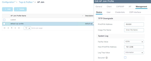
On the CLI, use this command:
C9800#ap name <APname> controller primary/secondary <WLCname> <WLC_IP>
You might also use the AP Priming profiles to assign the primary/secondary and tertiary. The AP priming profile is a controller configuration that
● defines primary, secondary, and tertiary controller assignments for APs
● enables centralized assignment of controllers for groups of APs or individual devices, and
● automates fallback and reconnection behavior when APs lose connection with their assigned controllers.
See more details in https://www.cisco.com/c/en/us/td/docs/wireless/controller/9800/17-15/config-guide/b_wl_17_15_cg/m_set_ap_priority.html#conf-ap-prime-profile.
By default, if the primary controller is unreachable and the AP joins the secondary (or tertiary) controller, while still been joined to the secondary/tertiary controller it will be sending discovery requests to the primary controller. In other words, APs have a “primary controller preference”, and as soon as the primary is reachable, they will try to join it.
This default behavior can be changed under AP Join Profile > CAPWAP > High Availability > AP Fallback to Primary.
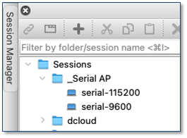
Primary/secondary/tertiary versus backup primary/backup secondary
There is an important difference between primary/secondary/tertiary and backup primary/backup secondary:
● Primary/secondary/tertiary WLCs are configured and saved at the AP level (not globally in the WLC). When the primary is set or changed, the AP will do a CAPWAP reset and join the new configured controller.
● Backup primary/backup secondary settings are configured at the WLC level and pushed to APs. These are only used when primary, secondary and tertiary are not responsive.
It is important to understand the different behavior between the two types of redundancy controllers:
● If an AP’s currently joined controller fails, the AP chooses an available controller from the list in this order: primary, secondary, tertiary, primary backup, and secondary backup.
● AP fallback (described in the previous section) applies only to the primary controller and no other backup controller.
In addition, to influence the controller failure detection time, you can configure various timers, including heartbeat timers and discovery request timers:
● Heartbeat Timeout (sec): this timer is used to detect a device failure and switch to the secondary/tertiary/backup primary/backup secondary controller.
● Fast Heartbeat Timeout (sec): 0 by default which means it is disabled. In some scenarios, when for example using N+1 and no HA SSO, one might want to enable the fast heartbeat. The fast heartbeat will send more heartbeats than the normal “heartbeat timeout” ensuring a faster switchover to the secondary controller in case the primary controller is unreachable. Be mindful when using this mechanism, since it requires a reliable connection. In general, the recommendation is to use it only in LAN scenarios where the latency is low and loss is rare.
● Discovery Timeout (sec): it determines how long the AP waits to send a new discovery request if it doesn’t receive a discovery response.
● Primary Discovery Timeout (sec): similarly to the discovery timeout it determines how long the AP waits to send a new discovery request to the primary controller when it doesn’t receive a discovery response from the primary controller. The difference is that this timer is used only for the primary controller when the AP has joined a non-primary controller (secondary, tertiary, backup primary and backup secondary).
● Primed Join Timeout (sec): during this time the AP will only try to join the primed primary/secondary/tertiary controllers and will ignore discovery responses received from other controllers.
Different than AireOS, the Catalyst 9800 allows you to configure the backup WLCs at the AP Join profile level, so for a group of APs, AireOS is only at the global level. On the WebUI, go to Configuration > Tags & Profiles > AP Join:
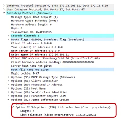
On the CLI, it’s under the AP profile:
C9800(config)#ap profile <name>
C9800(config-ap-profile)#capwap backup primary <name> <IP>
Access points will generate syslogs about important events for troubleshooting and serviceability. By default, they will use a local broadcast destination (255.255.255.255), to ensure that even when the AP is new out of the box, it is possible to obtain some information about possible problems by doing a local capture. For performance, security, and ease of troubleshooting, it is recommended that you set a unicast destination and store the AP logs for later analysis in case of problems.
To configure for all access points that will join the controller, set the syslog server IP address in the default AP profile:
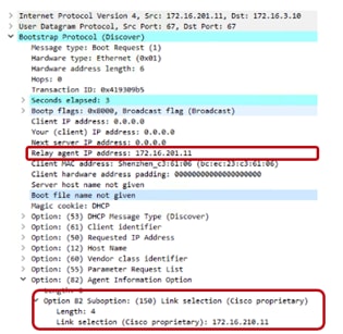
On the CLI, it’s under the default AP profile:
C9800(config)#ap profile default-ap-profile
C9800(config-ap-profile)# syslog host <IP>
The user can also decide to use a custom AP profile and tag to set the syslog server for a group of APs (for example, a different syslog server per location).
Note: If for some reasons, you want to disable syslog messages from the AP, then set the IP address to 0.0.0.0 in the AP Join profile.
Access Point Console Baud Rate
Traditionally, the AP console port used a default baud rate of 9600 bps for all connections, and this was the case for all C9800 IOS XE releases prior to 17.12.1. Starting with IOS XE 17.12.1, the default baud rate for all new APs and factory reset APs is now 115200 bps.
This was done to allow the APs to speed up the AP boot times, allowing for shorter wait times when APs need to reload (new AP boot, software upgrade, etc.). APs that were joined to the controller prior to 17.12.1 will maintain the default baud rate.
This leads to the case where deployments will have APs with one of two baud rates:
1. 9600 bps – all existing APs joined to the C9800 prior to upgrade
2. 115200 bps – all new APs and factory reset APs that join to the C9800 after upgrading to 17.12.1
Because of this, it’s recommended for the network admins to have separate settings to connect to the AP console. If the setting for one baud rate does not work, they can easily switch to the other.
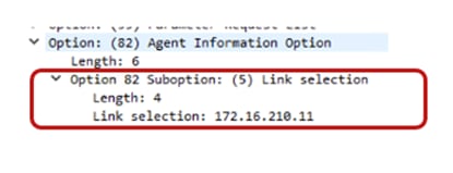
If a single baud rate is required, the recommendation is to move all APs to the 115200 bps to take advantage of the quicker boot times. There are currently 2 methods in which to do so:
1. Clear the config on existing APs to change the baud rate and have one way to console to all APs. However, this requires the APs to have static tag mapping with MAC address as the APs will lose their configured name and location, leaving the MAC address as the only persistent information.
2. Connect to each AP (via console, telnet, or SSH) and set the baud rate to 115200 bps.
AP# config boot baudrate 115200
This can be done manually or automated via WLAN Poller, an automation tool you can find on Cisco DevNet site: https://developer.cisco.com/docs/wireless-troubleshooting-tools/#!wlan-poller-wlan-poller
Cisco Discovery Protocol (CDP) for Access Points
By default, access points have CDP enabled in the AP Join Profile under AP Join Profile > Management > CDP Interface > CDP State.
Cisco recommends disabling CDP if the APs are not connected to a Cisco switch, this will avoid CDP flooding and the AP reporting a large CDP neighbor list.
This section covers the recommended settings for the controller as a network device.
Spanning Tree Protocol (STP) setting on uplink ports
The C9800 wireless controller, like AireOS WLC, is meant to act as a Layer 2 host from a network perspective. This means that it doesn’t participate in Spanning Tree, for example. To speed up network convergence, it is recommended that you enable PortFast or PortFast trunk configuration for the uplinks on the switch where the C9800 is connected.
Prune VLANs on controller uplink ports
To avoid unnecessary work by the controller data plane and prevent network loops, it is advisable to configure the trunk links between the WLC and the uplink switch(es) to only allow the required VLANs; specifically the wireless management interface VLAN and the centrally switched client VLANs. All the other VLANs should be pruned from the trunk links.
On the C9800 physical appliances, the service port (SP) is the out-of-band management port; it is the GigabitEthernet0 interface and is mapped to the Mgmt-intf VRF. This means that for traffic to be routed out of this interface, you have to configure a route in this VRF. This can be a default route or a specific route, depending on the network. Here is an example for the default route:
ip route vrf Mgmt-intf 0.0.0.0 0.0.0.0 <gateway>
In addition to WebUI and SSH access, it is possible to source control plane traffic from the SP, but you need to set the source interface instructing the C9800 to use the Mgmt-intf or the interface in that VRF.
This is sample configuration for TACACS+; it can be configured either globally:
ip tacacs source-interface GigabitEthernet0/0 vrf Mgmt-intf
or under a specific group server:
aaa group server tacacs+ demo
server name ISE
ip vrf forwarding Mgmt-int
exit
Use the Cisco IOS XE configuration guide for the other protocols.
Note: As of release 17.6, the following protocols and features are supported through the service port (SP): Cisco Catalyst Center, Cisco Smart Services Manager, Cisco Prime Infrastructure, Telnet, Controller GUI, DNS, File Transfer, GNMI, HTTP/HTTPs, LDAP, Licensing for Smart Licensing feature to communicate with CSSM, Netconf, NetFlow, NTP, RADIUS (including CoA), RESTCONF, SNMP, SSH, SYSLOG, TACACS+.
Address Resolution Protocol (ARP) proxy
By default, the Catalyst 9800 forwards ARP traffic by changing the destination MAC from broadcast to unicast. For example, if a wireless client-A sends an ARP packet to another wireless client-B, the Catalyst 9800 will forward the ARP packet using the unicast destination MAC B; client-B will reply and will also learn client-A’s MAC address. This default behavior optimizes the exchange of ARP packets between the two clients.
In Release 17.3, the Catalyst 9800 can be configured to act as a proxy for ARP traffic and respond on behalf of a registered client. The configuration is under the policy profile:
C9800(config)#wireless profile policy <name>
C9800(config-wireless-policy)#ipv4 arp-proxy
This is the recommended setting as it will save battery life on the wireless devices because the WLC will answer ARP on behalf of the device.
Note: This is also supported in FlexConnect mode, it needs to be explicitly configured in the Flex profile. See the config guide: https://www.cisco.com/c/en/us/td/docs/wireless/controller/9800/17-15/config-guide/b_wl_17_15_cg/m-sniffer-cg.html?bookSearch=true#proxy-arp-for-flex-wireless
In AireOS, enabling DHCP proxy for wireless clients is a best practice. For the C9800, DHCP proxy is not required, as Cisco IOS XE has embedded security features such as Dynamic Host Configuration Protocol (DHCP) snooping, Address Resolution Protocol (ARP) inspection, etc. that don’t require being a proxy for DHCP traffic. So there is not an equivalent setting in the 9800 Series wireless controller.
DHCP bridging is the recommended and default mode of operation for the C9800. This means that the client DHCP traffic gets bridged at the controller in the client VLAN mapped to the SSID or to the client via AAA override. If the DHCP server is not present on the client VLAN (which is usually the case), it’s recommended that you enable the DHCP relay function on the upstream switch. Here is a sample configuration for a Cisco Catalyst 9500 Series Switch acting as default gateway and DHCP relay for the wireless client traffic in VLAN 210:
interface Vlan210
description c9800-guest-vlan
ip address 172.16.210.254 255.255.255.0
ip helper-address 172.16.3.10
DHCP relay can be configured on the C9800 as well, but in that case a Layer 3 VLAN interface (SVI) needs to be configured to source such traffic. You may want to configure DHCP relay on the C9800 for multiple reasons. For example:
● The wireless team doesn’t have access to the next-hop switch configuration.
● You want to add option 82 information to the DHCP server.
The recommended way to configure DHCP relay on the Catalyst 9800 is under the “Advanced” tab of the SVI configuration: Configuration > Layer2 > VLAN; you can also define multiple DHCP servers and the option 82 relay settings:
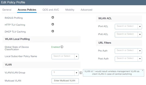
When using the relay function, the DHCP traffic will be sourced from the IP address of the client SVI and routed out of the interface that matches the destination (IP address of the DHCP server) in the routing table. In other words, the source IP and the IP of the outgoing interface might be different.
There are situations where you want to specify the source interface for the DHCP traffic instead of relying on the routing table to avoid possible issues in your network. This is the case when the next-hop network device (Layer 3 switch or firewall) is configured with Reverse Path Forwarding check. For example, let’s assume you have the wireless management interface configured on VLAN 201 and the client SVI on VLAN 210, acting as a DHCP relay for the client DHCP traffic. The default route points to the gateway on the wireless management VLAN/subnet. Here would be a snip of the config:
!
interface Vlan201
description Wireless Management
ip address 172.16.201.5 255.255.255.0
!
interface Vlan210
description Employee-SVI
ip address 172.16.210.21 255.255.255.0
ip helper-address 172.16.3.10
!
ip route 0.0.0.0 0.0.0.0 172.16.201.1
The traffic to the DHCP server 172.16.3.10 will be sourced from VLAN 210 (172.16.201.5) as the result of the ip helper-address command. The DHCP packet GIADDR is also set with the same IP. The outgoing interface is then chosen according to the IP routing table lookup and in this case, it would be the wireless management interface (WMI) VLAN.
The uplink switch configured with RFP check sees a packet coming from VLAN 201 but sourced from an IP of another subnet (VLAN 210) and will drop the packet.
To avoid this, the first step is to configure a specific source interface for the DHCP packets using the ip dhcp relay source-interface command: in this case you want DHCP packets to be sourced from the WMI interface (VLAN 201):
interface Vlan210
description Employee-SVI
ip address 172.16.210.21 255.255.255.0
ip helper-address 172.16.3.10
ip dhcp relay source-interface vlan 201
Note: To support the command “ip dhcp relay source-interface” in conjunction with option 82 parameters, you need to be using Release 17.3.3 or higher.
When using this command, both the source interface of the DHCP packets and the GIADDR are set to the interface specified in the DHCP relay command (Vlan 201, in this case). This is a problem, as this is not the client VLAN where you want to assign DHCP addresses. How does the DHCP server know how to assign the IP from the right client pool?
When the “ip dhcp relay source-interface” command is used, C9800 automatically adds the client subnet information in a proprietary suboption 150 of option 82 (called “link selection”), as you can see from the capture:
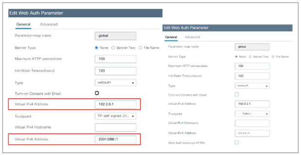
You need to make sure that the DHCP server used can interpret and act on this information. The recommendation is to change the C9800 configuration to use the standard option 82, suboption 5 to send the link selection information. You can do this by configuring the following global command:
C9800(config)#ip dhcp compatibility suboption link-selection standard
As you can see from the new capture below, the option for link selection has changed:
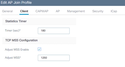
What do you have to do on the DHCP server? For Windows 2016 server, you have to create a dummy scope to “authorize” the IP of the relay agent. In our example, it’s the IP of the VLAN 201, the WMI (172.16.201.11). You have to add the IP to the scope and then exclude it from the distribution. Full instructions can be found here:
https://docs.microsoft.com/en-us/windows-server/networking/technologies/dhcp/dhcp-subnet-options
The controller has the ability to provide an internal DHCP server via the Cisco IOS XE software’s built-in functionality. The best practice is to use an external DHCP server, as this would be a box dedicated to this function. Nevertheless, if you want to use the internal DHCP server, this has been tested and hence is supported across all platforms for a maximum of 20% of the box’s maximum client scale. For example, for a 9800-80 that supports 64,000 clients, the maximum DHCP bindings supported is around 14,000. To verify the status of the internal DHCP:
C9800#show ip dhcp server stat
Memory usage 6840697
Address pools 11
Database agents 0
Automatic bindings 14780
Other important guidelines for the internal DHCP server:
● The internal server provides DHCP addresses to wireless clients, indirectly connected APs (the C9800 doesn’t support directly attached APs on any model), and DHCP requests that are relayed from APs. When you want to use the internal DHCP server, ensure that you configure SVI for the client VLAN and set the IP address as the DHCP server’s IP address.
● When clients use the internal DHCP server of the device, IP addresses are not preserved across reboots. As a result, multiple clients can be assigned to the same IP address. To resolve any IP address conflicts, clients must release their existing IP address and request a new one.
Note: Only DHCPv4 is supported. DHCPv6 is not supported in the internal DHCP server.
Related documentation:
The C9800 has a timeout for each client state (authentication, DHCP address negotiation, WebAuth pending, etc.). For DHCP, the controller has been configured with a default timer to allow for a client to complete a successful address negotiation. This timeout, called the IP-Learn timeout, is a fixed value, and it’s 120 seconds.
DHCP Scope and Lease design considerations
Size your DHCP scope considering all the possible devices that could join that area to prevent DHCP scope starvation: stationary but also roaming devices from other areas.
DHCP Lease is very important to reduce the load on DHCP server, prevent starvation and security issues.
The recommendation for DHCP lease: align it to the average dwell time in that environment. For example:
● Set it to a minimum of 12 hours for normal office deployments
● Set it to 8 hours for universities
● Set it to 1 hour for retailers
● Set it very low (e.g., 30 mins) for security reasons (reduced unauthorized time). This will generate a higher load in both the DHCP server and the controller, it might also lead to some traffic disruption for some client implementations. Also consider Random MAC and keep DHCP lease lower to avoid starvation
Wireless management IP addressing
The only required IP address for the C9800 wireless controller is the one assigned to the wireless management interface (WMI). This is the interface used for terminating CAPWAP traffic to the AP and to source any other management traffic.
Assigning an IP address to the service port (SP) is optional but remember that the SP on the physical appliance belongs to the Management VRF, so an IP address must be assigned accordingly. Here is a sample configuration for the SP with a route to connect to the out-of-band network:
interface GigabitEthernet0/0
description SP_out_of_band
vrf forwarding Mgmt-intf
ip address 10.58.55.246 255.255.255.0
negotiation auto
!
ip route vrf Mgmt-intf 10.58.0.0 255.255.0.0 10.58.55.254
Recommendations for setting the IP address on the WMI:
● Use an SVI for the WMI for the 9800 physical appliance and the 9800-CL in a private cloud.
● For the 9800-CL in a public cloud, you must use a Layer 3 port (it is automatically configured during bootstrap), meaning that there is no support for Sniffer mode AP and Hyperlocation.
● A loopback interface is used for the Cisco Catalyst 9800 Embedded Wireless Controller on the Cisco Catalyst 9000 switch family.
● A loopback interface is used by the internal DHCP server when in use (see section Internal DHCP server before using this functionality).
Wireless management interface VLAN tag
Cisco recommends using VLAN tagging for the wireless management interface of the WLC. To configure the wireless management traffic to be tagged, make sure there is no native VLAN command under the trunk configuration on the port/LAG. For example:
interface GigabitEthernet2
switchport trunk allowed vlan 201,210,211
switchport mode trunk
VLAN 201 is the wireless management interface VLAN and 210 and 211 are the client VLANs. Ensure that the corresponding VLAN is allowed on the switch port as well and is tagged by the trunk (non-native VLAN). In this sample configuration, the assumption is that the native VLAN (by default this is VLAN 1) is not used to carry any traffic.
Note: This should be done in most scenarios, except for small Embedded Wireless Controller (EWC)-based network deployments, in which all devices (AP, WLC, clients) might be on the same VLAN. This is a simple network, but it also has lower security.
Use of VLAN 1 in a Policy Profile
To configure the VLAN for client traffic, go to Configuration > Tags & Profiles > Policy. Under the Access Policies you can set the VLAN field. This is an important clarification related to the use of VLAN ID =1 (and VLAN name “default”) in the policy profile for the Catalyst 9800:
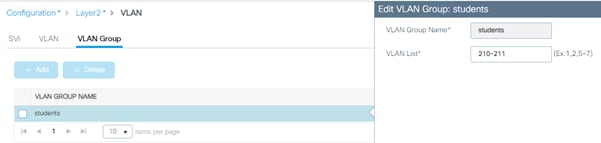
The behavior is different depending on the AP mode. For an AP in local mode/Flex Central switching:
● Specifying vlan-name = default, client is assigned to VLAN 1
● Using vlan-id 1, a client is assigned to the wireless management VLAN
There is a warning to remind a user of this.
For an AP in FlexConnect local switching mode:
● Specifying vlan-name = default, client is assigned to VLAN 1
● Using vlan-id 1, a client is assigned to the FlexConnect native VLAN
By default, if the user does not configure anything under the policy profile, the WLC assigns vlan-id 1 so clients will use the wireless management VLAN in local mode and the AP native VLAN for FlexConnect.
For centrally switched traffic, it is mandatory to configure a Layer 2 VLAN (or a pool of VLANs) mapped to the SSID, but the corresponding Layer 3 interface (SVI) is not needed. This is different from AireOS, in which a dynamic interface (Layer 3 interface and related IP address) is required. The recommendation for C9800 is not to configure an SVI for client VLAN, unless:
● You need to run DHCP relay on the C9800; this is either because this function cannot be configured on the next hop layer 3 switch (the default gateway for that VLAN) or because you want to add option 82 information (e.g., AP location, AP MAC, etc.) in the DHCP relayed packet.
● You want to enable mDNS Gateway and are running code before 17.9.1; in 17.9.1 and higher, mDNS gateway feature doesn’t need a client SVI interface anymore.
● You have static IP clients and are using VLAN groups, this requires SVIs, for more details see the configuration guide: https://www.cisco.com/c/en/us/td/docs/wireless/controller/9800/17-15/config-guide/b_wl_17_15_cg/m_conf_vlan_grp_vewlc.html#vlan-grp-supp-dhcp-stat-ip-cl
Note: If configuring multiple SVIs on the C9800, it is recommended to configure access control lists (ACLs) to prevent unauthorized communication between specific VLANs. For example, if client VLANs are configured, you should allow only client traffic from the correspondent subnet. Also, wired clients should not be able to connect to the box using the client SVI interface.
Compared to AireOS, in the C9800 the use of a virtual IP address (IPv4 and IPv6) is limited to Web Authentication, and it’s specifically needed for the redirect function and to install a Web Authentication certificate and have it been trusted. It is recommended that you configure a nonroutable IP address for the virtual interface, ideally not overlapping with the network infrastructure addresses. It is recommended that you set both the IPv4 and IPv6 virtual IP. You may use one of the options proposed in RFC 5737 for IPv4; for example, 192.0.2.0/24, 198.51.100.0/24, and 203.0.113.0/24 networks. For IPv6 you may use the prefix 2001:DB8::/32 specified in RFC 3849.
Note: In IPv6-only client networks, it is important to configure the IPv6 redirection address option.
If the Virtual IPs are not configured, the clients are sometimes redirected to the internal portal instead of the configured external portal.
The virtual IP address can be set in the global parameter map, and if you go through the Day 0 GUI for the initial setup, this is set to 192.0.2.1 by default for IPv4.
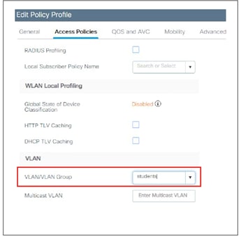
Link aggregation (LAG) mode is the preferred mode of operation, as it provides redundancy and additional network bandwidth. It should be used whenever multiple physical links to the same uplink switch are available. LAG mode is configured via the port channel feature on the C9800, and it doesn’t require a reload of the box to enable it. Here are some important recommendations:
● When using LAG, make sure all ports of the controller have the same Layer 2 configuration matching the switch side. For example, avoid filtering some VLANs in one port and not the others.
● For optimal load balancing among the physical ports of the port channel, use the src-dst-mixed-ip-port option. It is important to set the same option on the C9800 controller and the neighbor switch as well:
C9800(config)#port-channel load-balance src-dst-mixed-ip-port
● On a standalone C9800, both static (mode ON) and dynamic (Link Aggregation Control Protocol [LACP]/Port Aggregation Protocol [PagP]) port channel negotiation is supported. The mode has to be chosen on all interfaces that participate in the port channel group:
C9800(config-if)#channel-group 1 mode ?
active Enable LACP unconditionally
auto Enable PagP only if a PagP device is detected
desirable Enable PagP unconditionally
on Enable Etherchannel only
passive Enable LACP only if a LACP device is detected
● On an SSO pair, port channel has supported static mode (mode ON) since the initial release. LACP is also supported starting with release 17.1.
Preventing traffic leaks for guest or AAA override scenarios
A “black hole” VLAN is a specific configuration scenario in which the client VLAN configured on the controller is not forwarded on the trunk to the switch, is not present on the switch, or lacks any default gateway. Any client assigned to this VLAN can’t pass traffic or reach any network destination, with the goal of preventing a human configuration error and reducing the possibility of traffic leaks.
This scenario is targeted for:
● Guest access or mobility auto-anchor: Configure a black hole VLAN on the foreign level, to ensure that there is no traffic leak at the foreign level and that the only connectivity possible is through the anchor-assigned VLAN.
● AAA override: This requires all clients to get an assigned VLAN from the RADIUS server, or they can’t reach any network destination.
This section covers the recommended network settings for the APs.
APs and Wireless Management Interface VLAN
It is a best practice to place the Access Points in a different VLAN than the Wireless Management Interface (WMI) one, and this is usually the case in any production deployment. If for staging or testing purposes you need to configure the APs in the same VLAN as the WMI, it is recommended to limit the number of APs to a number less than 100.
AP-to-controller round-trip latency
For APs in local and fabric mode, the round-trip latency must not exceed 20 milliseconds(ms) between the access point and the controller. This is the same as in AireOS.
Use PortFast on AP switch ports
Use PortFast on AP switch ports for APs in local mode, fabric mode, or FlexConnect mode doing only central switched WLANs. To configure the switch port for PortFast, set the port to be connected as a host port, using the switch port host command or directly with the PortFast command. This allows a faster join process for an AP. There is no risk of loops, as the local mode APs never bridge traffic directly between VLANs. The port can be set directly on access mode.
Note: For APs in Flex mode and local switching, the switch port needs to be in trunk mode for most scenarios. For these, use spanning-tree portfast trunk on the switch port.
Prune VLANs for FlexConnect mode AP switch ports
For APs in FlexConnect mode, when using locally switched WLANs mapped to different VLANs (the AP switch port is in trunk mode), prune or limit the VLANs present on the port to match the AP-configured VLANs.
To optimize the TCP client traffic encapsulation in CAPWAP, it is recommended that you always enable the TCP maximum segment size (MSS) feature, as it can reduce the overall amount of CAPWAP fragmentation, improving overall wireless network performance. The MSS value should be adjusted depending on the traffic type and maximum transmission unit (MTU) of the WLC-to-AP path. In the C9800, TCP MSS adjust is enabled by default, with a value of 1250 bytes. This is considered a good value for most deployments, although it can be further optimized depending on your setup.
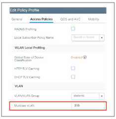
On the CLI, it’s under the AP profile (custom or default):
C9800(config)#ap profile custom
C9800(config-ap-profile)# tcp-adjust-mss ?
enable Enable TCP MSS for all Cisco APs
size TCP MSS configuration size
Because this is a setting under the AP Join profile in the C9800, you can decide to have different values for different groups of APs or locations.
This section gives the SSID/WLAN-related recommendations. In the C9800, these settings are not always applied to the WLAN configuration itself; most of the time the Policy profile is used. In general, security being the unchangeable part of a WLAN, it is configured on the WLAN profile. Other WLAN properties (QoS, VLAN, etc.) are configured on the Policy profile. This approach allows the user to define a common policy and apply it to multiple SSIDs without reconfiguring it all the time.
WLANs can operate by “hiding” the SSID name and answering only when a probe request has the explicit SSID included (that is, the client knows the name). By default, the SSID is included in the beacons, and APs will reply to null probe requests, providing the SSID name information even if clients are not preconfigured with it. Hiding the SSID does not provide additional security, as it is always possible to obtain the SSID name by doing simple attacks, and it has secondary side effects, such as slower association for some client types (for example, Apple iOS). Some clients don’t work reliably at all in this mode. The only benefit is that it prevents random association requests from devices trying to connect to it. It is recommended that you enable the broadcast SSID option to have the best client interoperability.
Broadcast SSID is enabled by default on the C9800 controllers.
Voice Cisco Centralized Key Management timestamp validation
Note: Cisco Centralized Key Management is deprecated. This section will be removed future updates.
If you have devices that are still using Cisco Centralized Key Management, it is strongly recommended that you change CCKM validation to 5 seconds to avoid roaming issues when using Cisco based clients (such as 8821 IP phones or Cisco workgroup bridges). Use the following command under the WLAN configuration to set this parameter:
C9800(config-wlan)#security wpa akm cckm timestamp-tolerance 5000
5000 is equal to 5 seconds.
VLAN group is the equivalent of the interface group/VLAN Select feature in AireOS. This feature enables you to use a single WLAN that can support multiple VLANs corresponding to different DHCP pools dynamically for load balancing. Clients get assigned to one of the configured VLANs using a hash of their MAC address, so the assignment is preserved over time, unless there is a VLAN group configuration change. The VLAN group pool feature will monitor the DHCP server responses and automatically stop using those VLANs with clients that fail to obtain a DHCP address assignment. Ensure that IP MAC-binding is configured on the Policy Profile(s) which use VLAN Group.
To enable this feature, perform the following steps:
Step 1. Create a VLAN group and add client VLANs:
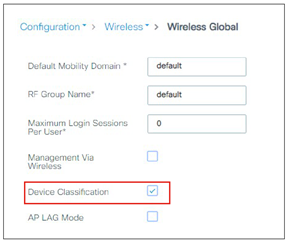
Step 2. Add the VLAN group to the Policy profile:
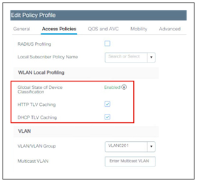
If VLAN groups are in use, it is recommended that you enable multicast VLAN to limit multicast on the air to a single copy on a predefined multicast VLAN.
Enable multicast VLAN under the Policy profile:
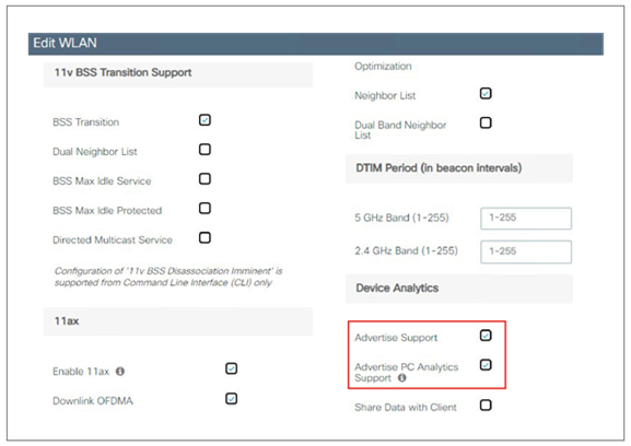
Knowing the client type can be extremely useful for troubleshooting scenarios, assigning policies per device type, or optimizing the configuration to adapt to them. Local profiling adds an easy way to detect the client types connected to the controller, without any external server dependencies. The controller will parse DHCP or HTTP requests from clients against a known set of client type rules to make a best-fit evaluation of the device type. The information is available on the WLC GUI or through the CLI.
To enable local profiling on a WLAN, you need to modify its associated Policy profile. Before doing so, you need to enable device classification globally on the controller:
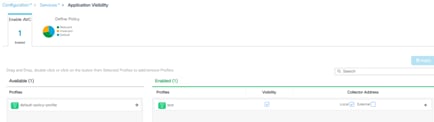
After that, client profiling can be enabled in the Policy profile:
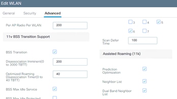
Any WLANs associated to this policy profile will have local profiling enabled.
Starting 17.1, C9800 supports Device Analytics feature to enhance the enterprise Wi-Fi experience. This feature, among other things, provides a set of data for analyzing wireless client device behavior. With device profiling enabled on the controller, information is exchanged between the client device and the controller and AP. Initially this applied to Apple and Samsung devices; starting release 17.6 the feature is extended to devices with Intel chipset (AC9560, AC8561, AX201, AX200, AX1650, AX210, AX211, and AX1675 chipsets). The C9800 receives additional client information from these devices and can use it to enhance device profiling on the box; the same information is also shared with Cisco Catalyst Center and displayed in Assurance.
Note: Intel Analytics requires PMF, you may consider configuring it as optional or required.
To enable this feature, go to the Advanced tab of WLAN configuration and enable “Advertise Support” and “Advertise PC Analytics Support”, the latter being the one for Intel devices:
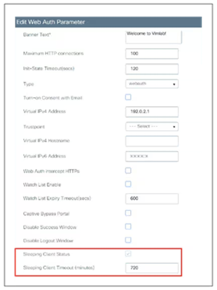
Application Visibility and Control
Application Visibility and Control (AVC) classifies applications using Cisco’s deep packet inspection (DPI) techniques with the Network-Based Application Recognition (NBAR) engine and provides application-level visibility into and control of the Wi-Fi network. After recognizing the applications, the AVC feature allows you to either drop or mark the traffic. Using AVC, the controller can detect more than 1400 applications. AVC enables you to perform real-time analysis and create policies to reduce network congestion, costly network link usage, and infrastructure upgrades. AVC is supported on all C9800 wireless controller platforms.
Note: AVC inspection may have a performance impact of up to 30% in terms of reduced client traffic throughput. It should be avoided on wireless controller setups that are running close to the maximum forwarding capacity of the platform.
On the Cisco Catalyst 9800 Wireless Controllers, AVC (for baseline application utilization) is enabled at the Policy profile level; the Policy profile can then be mapped to the WLAN (through the policy tag) so that AVC gets applied to the SSID. From the GUI, just click the arrow of the available profiles in the left column; once enabled, the profile with AVC will show up in the right column.
Note: In FlexConnect mode, only one AVC profile is supported per AP.
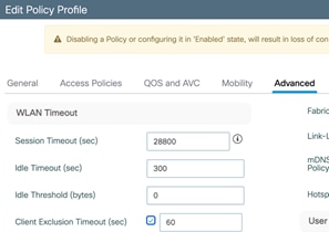
Enable 802.11k for optimal roaming
The 802.11k standard allows clients to request neighbor reports containing information about known neighbor APs that are candidates for roaming. The use of the 802.11k neighbor list can limit the need for active and passive scanning. A common problem that 802.11k helps solve is “sticky” clients, which usually associate with a specific AP and then hold on to that AP strongly, even when significantly better options are available from nearer APs.
The 802.11k feature can be configured directly on the WLAN under the Advanced settings:
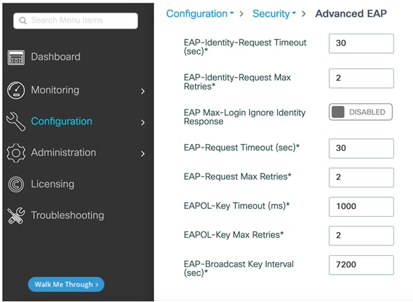
It is recommended that you enable 802.11k with dual-band reporting. With dual-band reporting enabled, the client receives a list of the best 2.4-5-GHz and 6-GHz APs upon a directed request from the client. The client most likely looks at the top of the list for an AP on the same channel and then on the same band as one on which the client is currently operating. This logic reduces scan times and saves battery power.
Note: Do not enable the dual-list option if using single-band clients or for deployment scenarios that use devices primarily configured for 5 GHz.
Note: 802.11k may cause problems on some legacy devices that react incorrectly to unknown information elements. Most devices will ignore 802.11k information, even if they do not support it, but for some it may lead to disconnections or failure to associate. These are corner cases, but it is advisable to test before enabling this option.
Like 802.11k, 802.11v was later introduced to help clients with roaming and battery saving. The main difference between 802.11k is that 802.11v proactively suggests clients to which AP to connect to. Here a few highlights of what 802.11v can do:
Directed Multicast Service: using Directed Multicast Service (DMS), the client requests the access point to transmit the required multicast packet as unicast frames. This allows the client to receive the multicast packets it has ignored while in sleep mode and also ensures Layer 2 reliability.
BSS Transition Management: allows APs to proactively suggest a better AP to roam to. It is applied in the following three scenarios:
● Solicited request — client can send an 802.11v Basic Service Set (BSS) Transition Management Query to the AP before roaming for a better option of AP to reassociate with.
● Unsolicited Load Balancing request — if an AP is heavily loaded, it sends out an 802.11v BSS Transition Management Request to an associated client asking them to roam to a different AP.
● Unsolicited Optimized Roaming request — If a client's RSSI and rate do not meet the requirements, the corresponding AP sends out an 802.11v BSS Transition Management Request to this client.
By default, the following options are enabled, and it is recommended to keep them enabled:
● BSS Transition
● BSS Max Idle
● Directed Mulicast Service
Note: It is recommended to enable both 802.11k and 802.11v (BSS Transition, BSS Max Idle Service and Directed Multicast Service).
Note: It is not recommended to enable “Unsolicited transition request” (CLI only) and “Optimized roaming” (as shown in the “Optimized roaming” section later in the document).
To change the 802.11v configuration, navigate to Configuration > Tags & Profiles > WLANs > Edit WLAN > Advanced tab and then the 11v BSS Transition Support section.
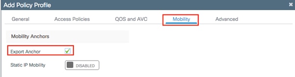
In the C9800, the Web Authentication parameters are under the parameter map, so that’s where you enable the Sleeping Client feature and the timeout. Navigate to Configuration > Security > Web Auth and edit the default parameter map or create a new one and set the Sleeping Client status and timeout.
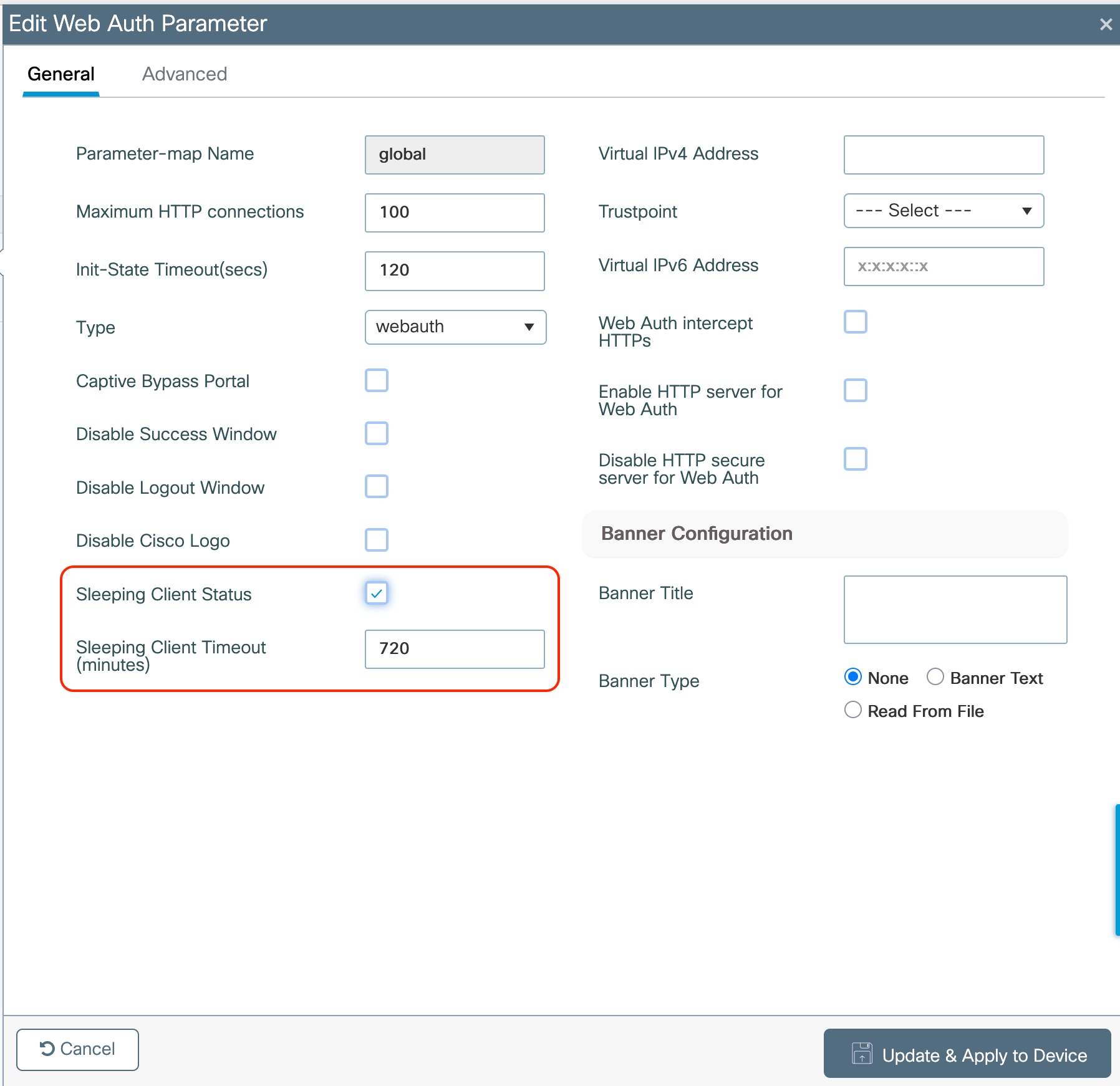
The parameter map is then associated to the WLAN profile under the Security > Layer 3 tab.
The sleeping timer becomes effective after the idle timeout. If using the Sleeping Client feature for Web Authentication, ensure that your idle timeout is lower than the session timeout, to prevent incorrect client deletion.
There are some client timers that need to be considered. The C9800 offers flexibility by configuring these timers under the Policy profile, so the same SSID could have different values according to the deployment requirements. Client timers are under the Policy Profile > Advanced tab:
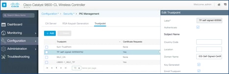
These are the recommended values:
● Session timeout = 28800 seconds (8h) is the recommended value for all SSIDs and policy profiles.
Note: In AireOS, a session timeout that is set to 0 (zero) means the maximum possible timeout. In the C9800 for releases before 17.4.1, it actually means “no session timeout,” so if you use the same setting as in AireOS, every roam on a C9800 network will be a slow roam and require a full reauthentication.
● Starting with Release 17.4.1, for WLAN configured for 802.1x authentication, if user configures any value between 0 (included) and 300 seconds, the session timeout is set automatically to 86400 seconds (24 hours), which is the maximum supported value.
● Set the per-WLAN user idle timeout to 300 seconds (5mins). This is important specifically in high density deployments, such as stadium, conferences, universities, where you have a lot of clients. With more and more devices using random mac addresses (also known as locally administered address), a longer idle time would force the AP to keep these random MAC entries and may cause AP to reject new client association due to maximum station count reached. Also, low idle time out will avoid big accounting updates being sent to AAA server.
Note: In scenarios where clients would move in and out of coverage areas or when the client is battery operated and may go to sleep frequently, you may consider increasing the idle time out to 3600 seconds (60 minutes), for example, to reduce the likelihood of client deletion. The exclusion timeout should be enabled, normally with exclusion set to 60 seconds. If a change in idle timeout is required, ensure the EAP-Broadcast Key Interval is higher than the idle timeout, to avoid “bulk” client deletions that could overload your AAA server. You can change the broadcast rotation timer in the Configuration > Security > Advanced EAP: section:
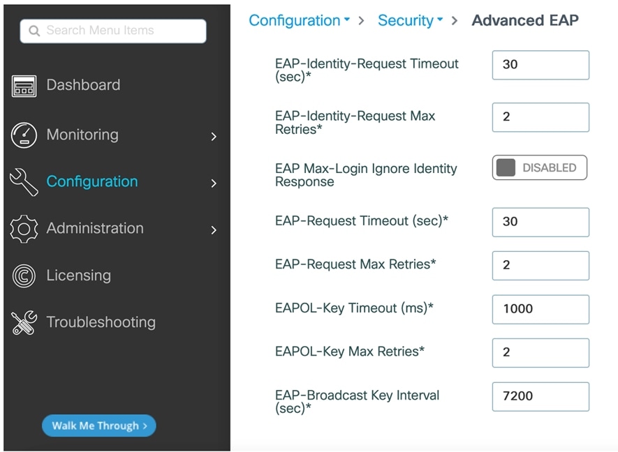
Anchoring an SSID and broadcasting it to local APs
For a (guest) SSID to be tunneled from Foreign to an Anchor WLC, you must configure the policy profile accordingly: On the Foreign, you select the Anchor IP under the Policy Profile > Mobility tab and on the Anchor WLC you enable the Export Anchor functionality under the same tab, as shown here:
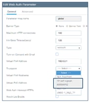
The moment you enable the setting above, the same profile cannot be associated to a WLAN/SSID that needs to be broadcasted on APs that are joined to the Anchor controller. This scenario doesn’t happen very often as the Anchor WLC is usually in the DMZ, dedicated to tunneled traffic and doesn’t have access points locally registered. But if this is the case, and you want the same SSID that is defined on the Foreign to be also broadcasted on the Anchor, then you need to define another policy profile on the anchor WLC, with a different name then the one with “Export Anchor” enabled, and use that policy profile to map it to the SSID in the policy tag to assign to the local APs.
Seamless roaming is not supported across policy profiles with different anchor points. This means clients may see connectivity issues if they try to roam between the two policies referencing different anchor points (for example one local and one auto-anchor) mapped to the same WLAN/SSID profile. We strongly recommend that Anchor WLC should not have any local serving policy profile which is associated with the same WLAN/ SSID profile defined on the Foreign WLC. This is especially important for fast roaming (FT, OKC, etc.), as client would be deauthenticated, and it will have to do a new full authentication to recover.
Passive client is a client that doesn’t send DHCP nor ARP packets after authentication is complete. In other words, it’s a client that doesn’t talk unless it is talked to (passive, precisely). The typical use case is a printer that is configured with a static IP address and is sitting idle.
For this type of client to become operational and be able to receive and then send traffic, you need to configure the Catalyst 9800 with the following settings: Under the policy profile you need to enable the passive-client feature, which basically instructs the WLC to disable the IP learn timeout that would prevent the client from going to RUN state:
wireless profile policy <policy-name>
passive-client
If the traffic is centrally switched (local mode or FlexConnect central switching deployment), you also need to enable ARP broadcast on the client VLAN:
vlan configuration <vlan-id>
arp broadcast
If the traffic is locally switched with the AP in FlexConnect mode, then you need to disable ARP proxy under the Flex profile, so that the ARP traffic can reach the passive client.
Wireless profile flex <flex-policy-name>
no arp-caching
In case, your Flex deployment also requires overlapping IP addresses across Flex sites (site tags), then you need an additional command on the flex profile as explained in the following configuration guide https://www.cisco.com/c/en/us/td/docs/wireless/controller/9800/17-15/config-guide/b_wl_17_15_cg/m-sniffer-cg.html#d5718e15126a1635
wireless profile flex <flex-profile-name>
ip overlap
Third party Work Group Bridge (WGB) is a network device that allow you to connect wired clients behind it and bridge them onto a wireless network. Differently from a Cisco WGB, a third party WGB does not perform the MAC/IP address registration to the WLC for its clients. This means that multiple wired devices with different IP addresses will be registered with the same MAC address, the one from the WGB itself. Usually this would be considered an ARP/DHCP drop and hence clients would not be allowed to connect. In order for C9800 to support 3rd party WGB and the wired devices behind it, you need to add the following command under the policy profile configuration:
wireless profile policy <policy-name>
no ip mac-binding
Note: This command disables IP device tracking on the controller. This command is supported for all modes (Local, FlexConnect, Fabric) starting 17.7.1.Disabling IP MAC binding will impact ARP proxy, WebAuth, NAC and DHCP profiling, they will stop working.
What about older versions? If you are running 17.3.4 or later versions of the 17.3.x train, you should configure instead the passive-client command under the policy profile in order to support 3rd party WGB. This is because the command no ip mac-binding is not supported in the 17.3.x train. If you are running 17.4.1, 17.5.1 or 17.6.x train, then you need to add both no ip mac-binding and passive-client under the policy profile to support 3rd party WGB in local/centralized mode.
The above settings disable the client device tracking feature and allow multiple clients behind the WGB with different IP addresses, to connect using the same MAC address. If the client traffic goes through the WLC, so in Local mode or FlexConnect central switching deployment, then you also need to enable ARP broadcast under the client VLAN. This is done with the following command:
C9800(config)#vlan configuration <vlan ID>
C9800(config-vlan-config)#arp broadcast
The following sections address best practices for security.
With the introduction of Wi-Fi 6E and Wi-Fi 7 WPA3 has become mandatory to take advantage of the new frequency and Wi-Fi 7 features.
Wi-Fi 7 is more restrictive than Wi-Fi 6E and not only requires WPA3 but also limits the Authentication Key Management (AKM) and ciphers allowed. Here are some of the requirements of Wi-Fi 7:
● WPA3 is required in all frequencies
● Beacon protection is mandatory
● GCMP-256 is required as a cipher
● Protected Management Frame is mandatory
The following tables are a summary of some of the supported combinations and their compatibility with Wi-Fi 6E and Wi-Fi 7.
For each WPA type, a combination is highlighted with “Compatibility Focus”. This is the configuration that we expect to be used by the most customers, although each scenario requires a dedicated analysis.
There is also a dedicated deployment guide that covers this matter in details: https://www.cisco.com/c/en/us/td/docs/wireless/controller/9800/technical-reference/wpa3-dg.html.
Acronyms used in the tables:
● AKM: Authentication and Key Management
● SAE: Simultaneous Authentication of Equals
● PMF: Protected Management Frame
● H2E: Hash to Element
● HPN: Hunting and Pecking
Enterprise
Table 5. Enterprise WPA3 combinations and compatibility
| WPA type |
AKM[s] |
Fast transition |
PMF |
AES (CCMP-128) |
GCMP-256** |
Compatibility |
Notes |
| WPA3 Enterp. |
802.1X-SHA256 |
Disabled |
✓ |
✓ |
✓ |
Wi-Fi 6E Wi-Fi 7 |
GCMP-256 added in 17.18.3, without it, compatibility issues with some Wi-Fi 7 clients |
| WPA3 Enterp. |
FT + 802.1X* |
Enabled |
✓ |
✓ |
✓ |
Wi-Fi 6E Wi-Fi 7 |
GCMP-256 added in 17.18.3, without it, compatibility issues with some Wi-Fi 7 clients |
| WPA3 Enterp. |
802.1X-SHA256 FT + 802.1X* |
Enabled |
✓ |
✓ |
✓ |
Wi-Fi 6E Wi-Fi 7 |
GCMP-256 added in 17.18.3, without it, compatibility issues with some Wi-Fi 7 clients |
| WPA3 Enterp. |
SUITEB192-1X |
Disabled |
✓ |
✕ |
✓ |
Wi-Fi 6E Wi-Fi 7 |
|
| WPA2 Enterp. WPA3 Enterp |
FT + 802.1X 802.1X |
Enabled |
Optional |
✓ |
✓ |
Wi-Fi 6E^ Wi-Fi 7^ |
GCMP-256 added in 17.18.3, without it, compatibility issues with some Wi-Fi 7 clients Allows legacy clients on 2.4/5 GHz ^ in 6GHz PMF is broadcasted as mandatory Compatibility Focus |
| WPA2 Enterp. |
802.1X |
Adaptive Disabled |
✕ |
✓ |
✕ |
Legacy (No 6E & 7) |
No 802.11be, no 6GHz |
* still uses SHA256, even if not explicit in its naming
** GCMP-256 not supported in C9105, C9115 and C9120
Note: for enterprise 802.1X there are some devices that require GCMP-256, this is only available from 17.18.3. If 17.18.3 is not used, these clients may not be able to associate. GCMP-256 will be added as well to 26.1.2 when it is released.
Personal
Table 6. Personal WPA3 combinations and compatibility
| WPA type |
AKM[s] * |
Fast transition |
PMF |
AES (CCMP-128) |
GCMP-256** |
Compatibility |
Notes |
| WPA3 Pers. |
SAE-EXT-KEY |
Disabled |
✓ |
✓ |
✓ |
No legacy Wi-Fi 7 |
AES (CCMP-128) allowed in 17.15 GCMP-256 mandatory in 17.18 |
| WPA3 Pers. |
SAE-EXT-KEY FT + SAE-EXT-KEY |
Enabled |
✓ |
✓ |
✓ |
No legacy Wi-Fi 7 |
AES (CCMP-128) allowed in 17.15 GCMP-256 mandatory in 17.18 |
| WPA3 Pers. |
SAE SAE-EXT-KEY |
Disabled |
✓ |
✓ |
✓ |
Wi-Fi 6 Wi-Fi 6E Wi-Fi 7 |
SAE “transition”, “transition” may need H2E/HPN Support for clients without SAE-EXT-KEY |
| WPA2 Pers. WPA3 Pers. |
PSK SAE SAE-EXT-KEY |
Disabled |
Optional |
✓ |
✓ |
Legacy Wi-Fi 6E Wi-Fi 7 |
Transition may need H2E/HPN AES (CCMP-128) allowed in 17.15 GCMP-256 mandatory in 17.18 Compatibility Focus |
| WPA2 Pers. WPA3 Pers. |
PSK SAE SAE-EXT-KEY FT-SAE-EXT-KEY FT-SAE |
Enabled |
Optional |
✓ |
✓ |
Legacy Wi-Fi 6E Wi-Fi 7 |
FT support Transition may need H2E/HPN AES (CCMP-128) allowed in 17.15 GCMP-256 mandatory in 17.18 Compatibility Focus |
| WPA2 Pers. WPA3 Pers. |
PSK SAE |
Disabled |
✓ |
✓ |
✕ |
Legacy Wi-Fi 6E No Wi-Fi 7 |
No 802.11be, but 6GHz supported |
| WPA2 Pers. |
PSK |
Disabled |
✕ |
✓ |
✕ |
Legacy (No 6E & 7) |
No 802.11be, no 6GHz |
* SAE hash to element (H2E) is required for Wi-Fi 6E & 7
** GCMP-256 not supported in C9105, C9115 and C9120
Enhanced Open (guest)
Table 7. Enhanced Open combinations and compatibility
| WPA type |
AKM[s] |
Fast transition |
PMF |
AES (CCMP-128) |
GCMP-256* |
Compatibility |
Notes |
| Enhanced Open |
OWE |
Disabled |
✓ |
✓ |
✓ |
Wi-Fi 6E Wi-Fi 7 |
AES (CCMP-128) allowed in 17.15 GCMP-256 mandatory in 17.18 |
| Enhanced Open |
OWE |
Disabled |
✓ |
✓ |
✕ |
Wi-Fi 6E No Wi-Fi 7 |
No 802.11be, but 6GHz supported |
| Enhanced Open |
OWE |
Disabled |
N/A |
✓ |
✕ |
Legacy No Wi-Fi 6E No Wi-Fi 7 |
No 802.11be, no 6GHz supported Requires 2 SSIDs** |
* GCMP-256 not supported in C9105, C9115 and C9120
A trustpoint is a certificate authority (CA) that you trust, and it is called a trustpoint because you implicitly trust this authority. Public Key Infrastructure (PKI) provides certificate management in the C9800. When you trust a given self-signed certificate (SSC), the PKI system will automatically trust any other certificates signed with that trusted certificate. This is used for providing certificate management for various functions and protocols such as Datagram Transport Layer Security (DTLS), HTTPS, Secure Shell (SSH), Secure Sockets Layer (SSL), and so on. Trustpoints are used on the C9800 for multiple functions:
● AP join (DTLS tunnel)
● HTTPs connection (GUI)
● WebAuth redirection
● Mobility tunnel
Let’s examine these one by one. Trustpoint for AP join secures the connection between WLC and AP. You can view this in the CLI by using the following command:
C9800#show wireless management trustpoint
All physical appliances use a Manufacturer Installed Certificate (MIC) by default. All virtual appliances use a Self-Signed Certificate (SSC):
Physical Appliance
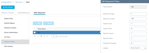
Virtual Appliance
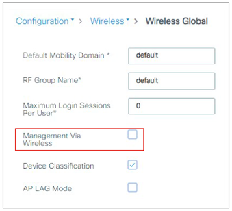
If you have some issues with AP joining, that’s probably the first thing to start troubleshooting, and it’s recommended that you follow these steps:
● Issue the following command to verify if the trustpoint is set:
show wireless management trustpoint
● If there is no trustpoint set, it is likely one of the causes, to set it:
◦ On the physical appliance simply reassign the CAPWAP certificate chain by using the following commands:
C9800(config)#default wireless management trustpoint
◦ On the virtual appliance you can generate a wireless trustpoint using the internal script in exec mode:
C9800#wireless config vwlc-ssc key-size 2048 signature-algo sha256 password 0 <password>
Note: This command needs to be run at the exec prompt (not in config mode).
◦ Validate the wireless configuration using the following exec command:
C9800#wireless config validate
It’s recommended that you statically assign the trustpoint used for HTTPS GUI access:
1. For the 9800-CL, identify the IOS-Self-Signed-Certificate using the show crypto pki trustpoint command or GUI:
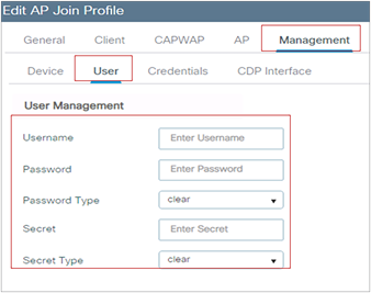
If this certificate is not present, is corrupted, etc., you can generate it again by restarting the HTTPS process with the config commands: no ip http secure-server followed by ip http secure-server
2. Assign the certificate to HTTPS (shown for both VM and appliance):
C9800-CL Physical appliance
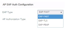
And the corresponding CLI command:
C9800(config)#ip http secure-trustpoint <name>
3. Verify the correct assignment (the example below is for the 9800-CL):
C9800#sh ip http server secure status
HTTP secure server status: Enabled
[snip]
HTTP secure server trustpoint: TP-self-signed-605569762
For WebAuth, you need a trustpoint for the HTTPS redirection. Again, the best practice is to assign it statically to the process; this can be done under the global parameter map (shown for the 9800-CL):
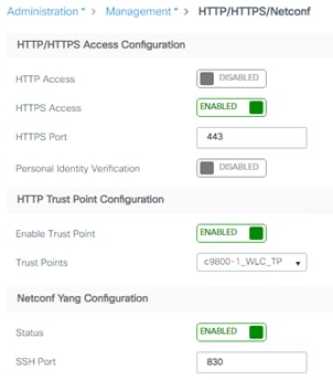
Note: The SUDI certificate should not be used for WebAuth/HTTP, we aware that it might be pushed by Catalyst Center.
The same settings on the CLI are made as follows:
parameter-map type webauth global
type webauth
virtual-ip ipv4 192.0.2.1
virtual-ip ipv6 FD00::0:2:1
trustpoint TP-self-signed605569762
Mobility tunnel uses CAPWAP and encrypts the control plane messaging using DTLS by default. WLC uses Wireless Management Trustpoint (AP Trustpoint) to establish this tunnel, so you don’t have to do anything special for this.
Trustpoint and Cisco Catalyst Center
Catalyst Center pushes its own self-signed certificate to the managed devices; the default certificate being ‘sdn-network-infra-iwan’. When the Catalyst 9800 has more than one certificates configured on the box (e.g. the self-generated trustpoint and the one pushed by Catalyst Center), it is strongly recommended to specify the certificate to be used for HTTPS access to the device. Not doing this may result in Catalyst 9800 picking the wrong one and breaking access to the graphical interface. As mentioned in the paragraph above, the way to do this is using the CLI command:
C9800(config)#ip http secure-trustpoint <truspoint-name>
or in the GUI going to the Administration > Management > HTTP/HTTPS/Netconf page and then selecting the specific certificate in the “HTTP Trust Point Configuration” section.
Local management password policies
You must enforce a strong password. The password policies allow enforcement of strong password checks on newly created passwords for additional management of users of controller and access points. The following are the requirements enforced on the new password:
● When the controller is upgraded from an old version, all the old passwords are maintained, even when they are weak. After the system upgrade, if strong password checks are enabled, the same is enforced from that time. The strength of previously added passwords will not be checked or altered.
● Depending on the settings done in the Password policy page, the local management and access point user configuration are affected.
On the C9800 wireless controller, the Password Strength and Management for Common Criteria feature is used to specify password policies and security mechanisms for storing, retrieving, and providing rules to specify user passwords.
For local users, the user profile and the password information with the key parameters are stored on the Cisco device, and this profile is used for local authentication of users. The user can be an administrator (terminal access) or a network user (for example, Point-to-Point Protocol [PPP] users being authenticated for network access).
For remote users, where the user profile information is stored in a remote server, a third-party AAA server may be used for providing AAA services, both for administrative and network access.
To configure a Password policy, go to Configuration > Security > AAA and define a policy for your password:
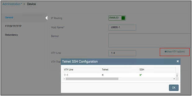
The user login policy allows you to limit the number of concurrent logins by different devices using the same user credentials. If you want to have this control for security reason, you should configure a value greater than the default of 0 (unlimited login). But please be aware that this could impact network devices that may be sharing the same username and password, for example, wireless phones using the same user profile for their wireless connection.
Configure user login policies by entering this command:
C9800(config)# wireless client max-user-login ?
<0-8> Maximum number of login sessions for a single user, 0-8 (0=Unlimited)
Verify the user login policies by entering this command:
C9800# show run | I max-user-login
Cisco IOS XE allows you to encrypt all the passwords used on the box. This includes user passwords but also SSID passwords, for example. To use encryption, first define an encryption key:
C9800(config)#key config-key password-encrypt <key>
and then use the following command:
C9800(config)#password encryption aes
This is recommended for protecting your password information.
Note: On the C9800, once the passwords are encrypted there is no mechanism to decrypt them, as a security best practice. The only way to recover would be to reconfigure the passwords.
Disable Management via Wireless
The Management via Wireless feature allows operators to monitor and configure the WLC using wireless clients connected to the wireless controller network. Management via wireless is disabled by default and should be kept disabled if security is a concern. To verify the setting on the GUI, go to Configuration > Wireless > Wireless Global:
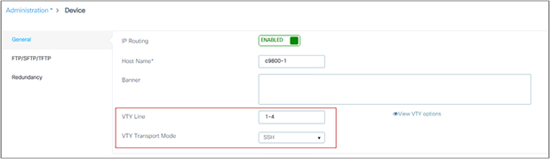
On the CLI, type:
C9800(config)#no wireless mgmt-via-wireless
Default AP console username and password
Cisco Secure Development Lifecycle (SDL) is a repeatable and measurable process designed to increase Cisco product resiliency and trustworthiness. Within SDL, the Cisco Product Security Baseline (PSB) has mandated the disabling of console access to access points via the default username and password (Cisco/Cisco). Starting with release 16.12.2s, the user must configure the access point credentials before being allowed to use the console, Telnet, or SSH. This is an enforced best practice for security reasons.
To define the custom credentials, go to the AP Join profile:
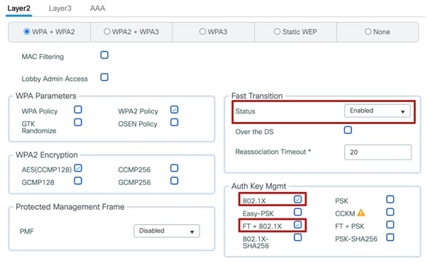
If the username and password are changed on the default Join profile, they will automatically be assigned to any AP. Then, using custom Join profiles, you can even have different credentials for different groups of APs.
802.1X authentication for AP ports
For increased security, configure 802.1X authentication between the AP and the Cisco switch. The AP acts as an 802.1X supplicant and is authenticated by the switch using EAP-FAST, EAP-PEAP, or EAP-TLS (Extensible Authentication Protocol [EAP] – Flexible Authentication via Secure Tunneling [FAST], Protected EAP [PEAP], or Transport Layer Security [TLS]) . This is configurable under the AP Join profile settings:
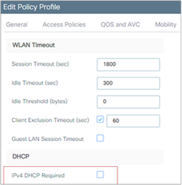
The new configuration model makes this feature very flexible: The AP 802.1X setting is not global anymore but can be configured only for a certain group of APs (those assigned to a certain AP profile and site tags). The 802.1X AP feature is supported across all supported APs.
The following is a sample configuration to enable 802.1X authentication on a switch port:
Switch# configure terminal
Switch(config)# dot1x system-auth-control
Switch(config)# aaa new-model
Switch(config)# aaa authentication dot1x default group radius
Switch(config)#
Switch(config)# interface gigabitethernet2/1
Switch(config-if)# switchport mode access
Switch(config-if)# dot1x pae authenticator
Switch(config-if)# dot1x port-control auto
Switch(config-if)# end
For increased security, confirm that HTTPS is enabled and HTTP is disabled for management access (these are the default settings):
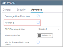
An SSC trustpoint for HTTPS will automatically be created at boot time when the system enables the secure web server process, but it’s not explicitly assigned for HTTPS. It’s recommended that you assign it explicitly, either via the GUI as shown above or via the CLI with the following command:
C9800(config)#ip http secure-trustpoint <trustpointname>
After you have assigned it, it will show up in the configuration:
C9800#sh ip http server status
[snip]
HTTP server active session modules: ALL
HTTP secure server capability: Present
HTTP secure server status: Enabled
HTTP secure server port: 443
HTTP secure server ciphersuite: aes-128-cbc-sha dhe-aes-128-cbc-sha
ecdhe-rsa-aes-128-cbc-sha rsa-aes-cbc-sha2 rsa-aes-gcm-sha2
dhe-aes-cbc-sha2 dhe-aes-gcm-sha2 ecdhe-rsa-aes-cbc-sha2
ecdhe-rsa-aes-gcm-sha2 ecdhe-ecdsa-aes-gcm-sha2
HTTP secure server TLS version: TLSv1.2 TLSv1.1
[snip]
HTTP secure server trustpoint: c9800-1_WLC_TP
HTTP secure server peer validation trustpoint:
HTTP secure server ECDHE curve: secp256r1
HTTP secure server active session modules: ALL
Via the CLI, you can also decide to define your own TLS version:
C9800(config)#ip http tls-version ?
TLSv1.0 Set TLSv1.0 version Only
TLSv1.1 Set TLSv1.1 version Only
TLSv1.2 Set TLSv1.2 version Only
and cipher suite:
C9800(config)#ip http secure-ciphersuite ?
3des-ede-cbc-sha Encryption type tls_rsa_with_3des_ede_cbc_sha ciphersuite
aes-128-cbc-sha Encryption type tls_rsa_with_aes_cbc_128_sha ciphersuite
aes-256-cbc-sha Encryption type tls_rsa_with_aes_cbc_256_sha ciphersuite
dhe-aes-128-cbc-sha Encryption type tls_dhe_rsa_with_aes_128_cbc_sha ciphersuite
dhe-aes-cbc-sha2 Encryption type tls_dhe_rsa_with_aes_cbc_sha2(TLS1.2 & above) ciphersuite
dhe-aes-gcm-sha2 Encryption type tls_dhe_rsa_with_aes_gcm_sha2(TLS1.2 & above) ciphersuite
ecdhe-ecdsa-aes-gcm-sha2 Encryption type tls_ecdhe_ecdsa_aes_gcm_sha2 (TLS1.2 & above) ciphersuite
ecdhe-rsa-3des-ede-cbc-sha Encryption type tls_ecdhe_rsa_3des_ede_cbc_sha ciphersuite
ecdhe-rsa-aes-128-cbc-sha Encryption type tls_ecdhe_rsa_with_aes_128_cbc_sha ciphersuite
ecdhe-rsa-aes-cbc-sha2 Encryption type tls_ecdhe_rsa_aes_cbc_sha2(TLS1.2 & above) ciphersuite
ecdhe-rsa-aes-gcm-sha2 Encryption type tls_ecdhe_rsa_aes_gcm_sha2(TLS1.2 & above) ciphersuite
rsa-aes-cbc-sha2 Encryption type tls_rsa_with_aes_cbc_sha2(TLS1.2 & above) ciphersuite
rsa-aes-gcm-sha2 Encryption type tls_rsa_with_aes_gcm_sha2(TLS1.2 & above) ciphersuite
As with secure web access, confirm that SSH is enabled and Telnet is disabled to the controller for better security. You can confirm this by clicking View VTY Options under Administration > Device:
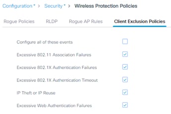
As with any other Cisco IOS XE box, you would follow the same configuration to enable or disable Telnet and SSH. This is easily done in the GUI:
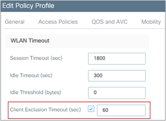
Related documentation:
Enable 802.11r Fast Transition
802.11r is the IEEE standard for fast roaming, in which the initial authentication handshake with the target AP (that is, the next AP that the client intends to connect to) is done even before the client associates to the target AP. This technique is called Fast Transition (FT).
Keep in mind that devices without 11r support cannot join an SSID where “FT only” is configured.
Before the introduction of Adaptive 802.11r, in order to leverage 802.11r on a wireless network with different type of devices, you would have needed to create a separate WLAN with FT enabled and another WLAN with FT disabled to allow the non-11r devices to join the network. This was not very practical; Cisco worked with the device ecosystems partners like Apple and Samsung to support Adaptive FT which allows to have FT and non-FT capable devices on the same SSID. In the C9800, Adaptive FT is enabled by default, and it’s useful when you have Apple and Samsung devices in your network.
The reality is that you usually have a mix of client types and capabilities in your network and some non-FT capable clients may experience issues in connecting to a WLAN with Adaptive FT; the recommendation from Cisco is to configure a single WLAN with “802.11r mixed mode”, to allow for compatibility between 802.11r and non-802.11r clients: Set Fast Transition to enabled and select both FT and non-FT Authentication and Key Management (AKM) modes. This is called “802.11r mixed mode” as it allows clients to choose the AKM with or without 802.11r depending on their capability. Below is a configuration example for WPA/WPA2 security and 802.1x AKM:
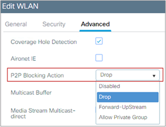
For best client interoperability, it’s recommended to keep the “over the DS” setting disabled.
Using 802.11r is important besides speeding up roaming; you can lower the total usage of the authentication services, as clients can do secure roaming without incurring full authentication at each AP change; this has benefits both in roaming speed and overall reduced authentication load on the AAA server.
Note: please refer to section titled WPA3 to learn more about fast transition in combination with WPA3.
To enhance security, Cisco recommends that all clients obtain their IP addresses from a DHCP server. The DHCP Required option in the Policy profile settings allows you to force clients to request or renew a DHCP address every time they associate to the WLAN before they are allowed to send or receive other traffic in the network. From a security standpoint, this allows for more strict control over the IP addresses in use.
But you need to analyze this setting carefully, as it might have an effect on the total time, during roaming, before traffic is allowed to pass again. Additionally, it might affect some client implementations that do not renew the DHCP address until the lease time expires. This depends on the client type; for example, Cisco 8821 IP phones might have voice problems during roaming if this option is enabled, as the controller does not allow voice or signaling traffic to pass until the DHCP phase is completed. Another example may include Android and some Linux distributions that renew the DHCP address only halfway through the lease time, but not on roaming. This may be a problem if the client entry expires. Some third-party printer servers might also be affected.
In general, it is a good idea not to use this option if the WLAN has non-Windows clients. This is because stricter controls might cause connectivity issues based on how the DHCP client side is implemented.
The option is under the Policy profile, which again gives flexibility to use the setting for a certain group of APs, even when broadcasting the same SSID/WLAN:
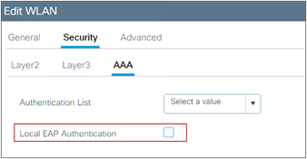
Note: Never enable DHCP Required for a WLAN supporting voice or video services, or when the wireless devices do conservative DHCP renewal on roaming.
In large-scale Fabric deployments, the replication and synchronization of IP-to-MAC bindings across APs increases the Controller’s processing overhead. As the number of clients and APs grows, this additional overhead can have an impact on the overall performance and scalability of the WLC.
For this reason, enabling the DHCP Required option is not recommended for SD-Access Fabric Wireless deployments
We recommend not using the following command, limiting the maximum accepted HTTP connections may lead to WebAuth and WebUI failures on different scenarios.
ip http max-connections
The default value is 300, decreasing it will impact both WebUI access and WebAuth sessions, the recommendation is to not modify the default value.
Aironet IE is a Cisco proprietary attribute used by Cisco devices for better connectivity and troubleshooting. It contains information such as the access point name, load, and number of associated clients in the beacon and probe responses of the WLAN that are sent by the AP. It’s used by some site survey tools to get more information from the network. Currently, when enabling Aironet IE, Advertise AP Name is also enabled and vice-versa.
This setting should be used for:
● AP name broadcasting for site surveys
● Cisco Workgroup Bridges (WGB)
● AP Authentication (more details in this link)
● Cisco legacy voice device support (8821 or 7925 IP phones, etc.)
● Cisco Centralized Key Management (CCKM), which is a deprecated feature
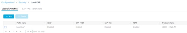
C9800# conf t
C9800(config)# wlan <profile-name> <wlan-id> <ssid>
C9800(config-wlan)# ccx aironet-iesupport
When a user fails to authenticate, the controller can exclude the client. The client cannot connect to the network until the exclusion timer expires or is manually overridden by the administrator. This feature can prevent authentication server problems due to high load, caused by intentional or inadvertent client security misconfiguration. It is strongly advisable to always have client exclusion configured on all WLANs, except for very rare or corner cases. Client exclusion can act as a protective mechanism for the AAA servers, as it will stop authentication request floods that could be triggered by misconfigured clients. Exclusion detects authentication attempts made by a single device. When the device exceeds a maximum number of failures, that MAC address is not allowed to associate any longer. The C9800 wireless controller excludes clients when any of the following conditions are met:
● Five consecutive 802.11 association failures
● Three consecutive 802.1X authentication failures
● IP theft or IP reuse, when the IP address obtained by the client is already assigned to another device
● Three consecutive Web Authentication failures
These are configurable at the global protection policies level:
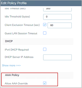
It is possible to configure how long a client remains excluded, and exclusion can be enabled or disabled at the Policy profile level:
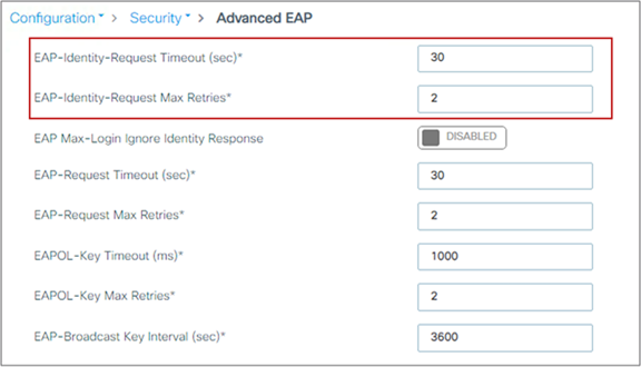
Peer-to-peer (P2P) blocking is a per-WLAN setting, and each client inherits the P2P blocking setting of the WLAN to which it is associated. It enables you to have more control over how traffic is directed. For example, you can choose to have traffic bridged locally within the controller, dropped by the controller, or forwarded to the upstream switch in the client VLAN.
This setting can prevent a client from attacking another client connected to the same WLAN, but it is important to keep in mind that using the drop option will prevent any application that can communicate directly between clients, such as chat or voice services. It makes sense to use P2P blocking on a guest SSID, as you just want clients to talk to the Internet.
The setting is enabled in the WLAN profile:
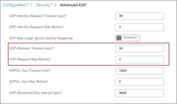
Disable this feature for WLANs supporting voice or video services, or for any scenario where direct client-to-client communication is required.
Note: In FlexConnect mode with local switching, as traffic is not going through the controller, P2P blocking is applied only to traffic from clients connected to the same AP. It will not apply to inter-AP traffic. Similarly, in SD-Access mode, this setting really has no effect, as the client traffic is always sent to the fabric edge switch for policy to be applied. P2P blocking will also not block traffic coming from another WLC in the Mobility group.
Local EAP is an authentication method that allows users and wireless clients to be authenticated locally on the controller instead of using a RADIUS server. Using local EAP in an enterprise production environment is not recommended for scalability reasons.
To check if a WLAN is configured to use local EAP, look under the AAA settings:
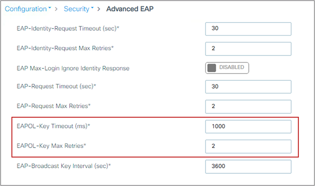
If you do want to enable it, click the checkbox, but first you need to create a Local EAP profile that establishes which EAP protocols to use. In case shown below, it’s configured for EAP-FAST:
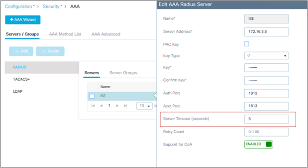
Wireless management VLAN mapping to WLAN (via policy profile)
To avoid any possible errors that could lead to clients being assigned to the WLC’s wireless management VLAN, it is advisable not to configure any policy profile to use the wireless management VLAN, so that the related SSID will not have traffic forwarded to the management subnet.
In the scenario of an auto-anchored WLAN, in which the foreign controller would forward all traffic to the anchor, it is still recommended that you set the Policy profile on the foreign controller to a “dummy” VLAN, so that traffic that doesn’t reach the anchor controller will be black-holed. This is also important if you have defined the wireless management interface as a layer 3 port, meaning using a configuration like this:
interface GigabitEthernet2
description L3 WMI
no switchport
ip address <ip_address> <mask>
end
wireless management interface GigabitEthernet2
WMI on a L3 port is not recommended unless using a C9800-CL in public cloud; but in case you have WMI as a L3 port and C9800 is acting as a Foreign WLC, please set the VLAN in the policy profile to something other than VLAN 1.
Also remember that on C9800, for central switching WLANs, when mapping the VLAN to the WLAN in the policy profile, there is a special handling for VLAN 1 and default VLAN:
● If vlan-name = default, client is assigned to VLAN 1
● If vlan-id is explicitly set to 1, client is assigned to the wireless management VLAN
There is a warning to remind you of this.
If designing for identity-based networking services, in which the wireless clients should be separated into different groups for security reasons and get, for example, different VLANs, different Scalable Group Tags (SGT), or other security policies, consolidate WLANs with the AAA override feature.
This feature allows you to assign per-user settings or attributes while using one common SSID. Besides the possible security improvements, AAA override can also help in collapsing different WLANs/SSIDs into a single one, with significant improvements in overall RF utilization (fewer beacons and less probe activity).
On the C9800, the AAA override setting is defined on the Advanced tab in the Policy profile. This allow the user to have the same 802.1X SSID configured for AAA override in one location (group of APs = policy tag) and not in another, if desired. Usually, though, the AAA setting will be common among all APs.
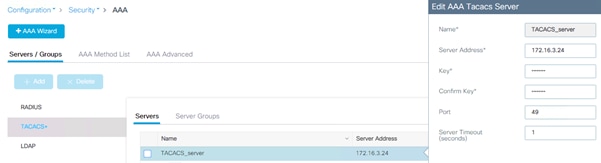
Also, be advised that for AAA override to work, the Catalyst 9800 needs to be configured to authorize settings received via RADIUS from the server. Make sure you have this line aaa authorization network in your configuration, pointing to an authorization list and a server-group name.
AAA VLAN and Fabric VNID Override
VLAN override is a well-known and commonly used feature in wireless. It allows you to apply basic user group segmentation policies by having one common SSID and returning a different VLAN/subnet based on the group the user belongs to.
In SD-Access, the segmentation is hierarchical and can be at the VRF level (macro segmentation) and at the SGT level (micro segmentation). The WLC (AireOS or Cisco IOS XE based), being a Layer 2 box, doesn’t understand VRF and uses the concept of a Layer 2 virtual network identifier (VNID) instead. So for AAA override in SD-Access Wireless, the user can return a different Layer 2 VNID based on the user group, and that VNID is mapped on the switch to a VLAN interface (SVI) and so to a subnet and a VRF.
Here are important things you need to know about AAA override with the C9800:
● For non-fabric deployments, VLAN AAA override can be implemented using either the Tunnel-Private-Group-ID or Airespace-Interface-Name. Both work, as the C9800 can take both attributes simultaneously, using the appropriate one and discarding the other
● For fabric deployments, the C9800 currently supports only Airespace-Interface-Name to pass the Layer 2 VNID information.
Note: AireOS can work only with Airespace-Interface-Name in fabric and non-fabric deployments.
EAP Identity request timeout and maximum retries
The default timeout and maximum retries for EAP identity requests are set to address the majority of use cases. You might need to increase these parameters for some client authentication scenarios. For example, you might need to increase them when implementing one-time passwords on smart cards, or in general when a user interaction is needed to answer the initial identity request. You might also need to decrease these parameters to improve the client experience by lowering the recovery time in case of failure.
To verify default EAP identity timeouts and change the values if needed, go to Configuration > Security > Advanced EAP:
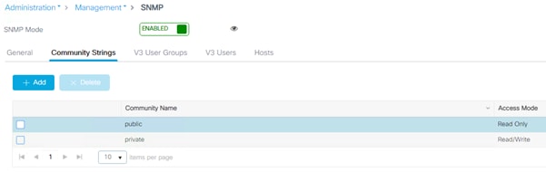
In the CLI, use the following command:
C9800(config)#wireless security dot1x identity-request ?
retries Maximum number of EAP ID request retries
timeout no description
EAP request timeout and maximum retries
During the 802.1X authentication phase, in the event of an EAP retry due to packet loss or lack of response from the client, the WLC may retry the EAP request. Some clients may not properly handle fast retry timers, so this setting may need adjustment depending on client types; this is important to facilitate fast recovery for bad RF environments.
It is difficult to give a general recommendation, but acceptable values are around 2 seconds in most cases, and up to 30 seconds for slow clients (phones), so usually this timeout is set to 30 seconds to account for worst-case scenarios. To show the default timeouts and eventually change them:
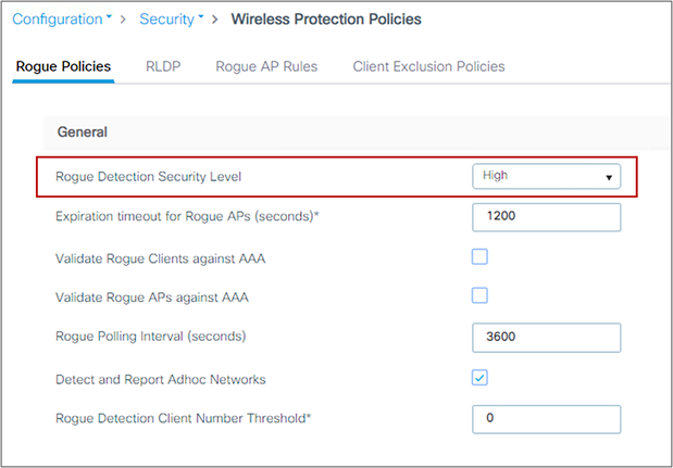
In the CLI, use the following command:
C9800(config)#wireless security dot1x request ?
retries Maximum number of EAP ID request retries
timeout no description
EAPoL key timeout and maximum retries
The EAP over LAN (EAPoL) timeout should be as minimal as possible for voice clients, such as the 7925 or 8821 IP phones. Normally, 400 to 1000 milliseconds can work correctly in most scenarios.
The maximum retry counter has a direct implication for several of the KRACK attacks reported in 2017 for wireless clients using WPA and WPA2. If the counter is set to zero, it can prevent most attacks against clients that are not yet patched against this vulnerability. But this has implications for authentications performed in bad RF scenarios or over a WAN network with possible packet loss, as using zero may cause a failed authentication process if the original packet is lost.
To show the defaults and change the EAPoL parameters, use the following GUI settings:
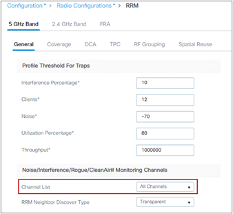
RADIUS authentication and accounting servers should have 5 seconds as the minimum value for server timeout to prevent early expiration of the client authentication process during load. Set the timeout for RADIUS authentication and accounting servers by entering these settings:
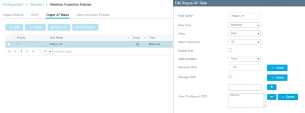
In the Catalyst 9800, it is important to configure the dead-criteria and the deadtime timers, especially when using multiple AAA servers and applying load balancing; with these commands the Catalyst 9800 marks a non-responsive server as “dead” and moves to the backup server. To configure these timers, use the following CLI commands:
radius-server dead-criteria time 5 tries 3
radius-server deadtime 5
“Deadtime” specifies the amount of time the server remains in dead status after dead-criteria marks it as dead. To make sure that the AAA server is actually “alive” after the deadtime, and to avoid sending requests to a still unreachable AAA server, you can configure an active probe under the server definition:
C9800(config)#radius server <name>
C9800(config-radius-server)#automate-tester username <username> probe-on
The username in this command can be a dummy one; it does not need to exist on the AAA server database. Note that if the server is reachable but the backend database (i.e., Active directory) or any other services are not working, WLC would still consider the server alive.
RADIUS Network Device configuration
When creating an entry in your RADIUS server for the controller, if you’re using HA SSO, you must configure the following 3 IP addresses:
● Wireless management interface (WMI)
● The active controller Redundancy management interface (RMI)
● The standby controller Redundancy management interface (RMI)
The standby controller always uses its RMI IP to authenticate SSH sessions. The active controller uses both RMI and WMI to reach out to the AAA server.
RADIUS interim accounting sends accounting-request packets, with the accounting updates, from the network access server (NAS) to a RADIUS server. The RADIUS accounting requests send data, such as VLAN ID, authentication methods, and so on, to keep the NAC updated.
In high-scale scenarios, it might be advisable to disable RADIUS interim accounting to lower the server-load on the NAC. See the configuration guide for details: https://www.cisco.com/c/en/us/td/docs/wireless/controller/9800/17-15/config-guide/b_wl_17_15_cg/m_interim-accounting.html
It is a best practice to increase the retransmit timeout value for TACACS+ AAA servers if you experience repeated reauthentication attempts or if the controller falls back to the backup server when the primary server is active and reachable. This is especially true when implementing one-time passwords. The server timeout can be configured when creating the TACACS+ server entry, and usually a value of 1 second is recommended:
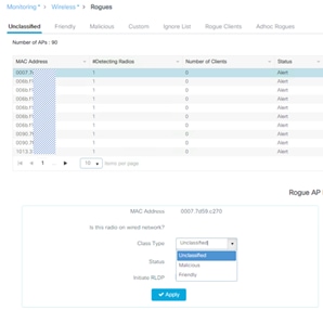
Note: SNMP communities will be deprecated in the future, SNMPv3 with username/password is the recommended way forward.
Check on the SNMP communities and make sure you don’t use default or very well-known ones such as “private” and “public,” as this could represent a security risk in most deployments.
You may want to delete and re-create new ones if these default ones are configured:
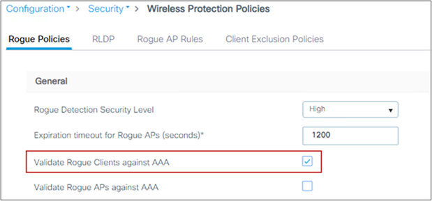
Rogue management and detection
Rogue wireless devices are an ongoing threat to corporate wireless networks. Network owners need to do more than just scan the unknown devices. They must be able to detect, disable, locate, and manage rogue and intruder threats automatically and in real time. Rogue APs can disrupt wireless LAN operations by hijacking legitimate clients and using plain text, denial-of-service attacks, or man-in-the-middle attacks. That is, a hacker can use a rogue AP to capture sensitive information, such as passwords and usernames. The hacker can then transmit a series of clear-to-send (CTS) frames, which mimic an AP informing a particular wireless LAN client adapter to transmit and instructing all others to wait. This scenario results in legitimate clients being unable to access the wireless LAN resources. Thus, wireless LAN service providers seek to ban rogue APs from the air space. The best practice is to use rogue detection to minimize security risks, such as in a corporate environment. However, there are certain scenarios in which rogue detection is not needed, for example, in an OfficeExtend access point (OEAP) deployment, citywide, and outdoors. Using outdoor mesh APs to detect rogues would provide little value while incurring resources to perform the analysis. Finally, it is critical to evaluate (or avoid altogether) rogue auto-containment, as there are potential legal issues and liabilities if left to operate automatically. Some best practices, listed in the following sections, improve efficiency in maintaining the rogue AP list and making it manageable.
At a minimum, the security level should be set to High. Do this in the GUI:
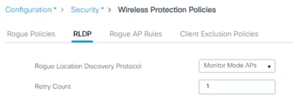
Set “monitor all channels” for better rogue detection. The controller maintains a single channel scan list for the RRM metrics (noise, interference) and for rogue detection monitoring. The list can be configured to focus on Dynamic Channel Assignment (DCA) channels (those channels that will be automatically assigned to APs) or to country channels (those valid only in the configured country), or to scan all possible channels. The latter is the best option to ensure that any rogue using an uncommon channel can be detected properly. The drawback is that with a longer channel list, the AP will have to go off-channel more frequently inside the configured channel scan interval. Given these trade-offs, here are some recommendations:
● For higher security, choose to scan all channels.
● Choose DCA channels for higher performance, as the system will scan the least number of channels.
● For a balance of performance and security, choose the country channel option.
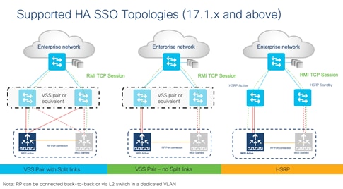
Define appropriate malicious rogue AP rules
Define malicious rogue AP rules to prioritize major and critical rogue AP alarms that require immediate attention and mitigation plans. Critical or major rogue AP alarms are classified as malicious and are detected on the network. Each rogue rule is composed of single or multiple conditions, and you set AND (match all) or OR (match any) logic to match the rule. The recommended malicious rogue AP rules are as follows:
● Managed SSIDs: Any rogue APs using managed SSIDs, the same as your wireless infrastructure, must be marked as malicious. Administrators need to investigate and mitigate this threat.
● Minimum RSSI >-70 dBm: This criterion normally indicates that unknown rogue APs are inside the facility perimeters and can cause potential interference with the wireless network. This rule is recommended only for enterprise deployments that have their own isolated buildings and secured perimeters. It is not recommended for retail customers or venues that are shared by various tenants, where Wi-Fi signals from all parties normally bleed into each other.
● User-configured SSIDs or substring SSIDs: Monitor any SSIDs that use different variations or combinations of characters in your production SSIDs.
For the rule, you need to set a state, which is either Alert, Contain, or Delete. It is recommended that you use Alert. Here is how to configure the rogue AP rule:
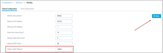
Note: There are legal implications for containing rogue APs. Additionally, containing rogues using infrastructure APs will have a significant negative impact on wireless service during operation, unless dedicated APs are used for containment activities.
Identify and update friendly rogue AP list
Regularly research and investigate, and then remove, friendly rogue APs from the “unclassified” rogue AP list on a regular basis (weekly or monthly). Examples of friendly rogue APs are as follows:
● Known internal friendly rogue APs, such as those within the facility perimeters, and known AP MAC addresses imported into the friendly rogue AP list.
● Known external friendly rogue APs, such as those found in vendor shared venues and neighboring retailers.
Go to Monitor > Wireless > Rogues to do this:
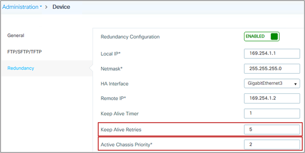
AP Rogue Detection Configuration
It is possible to configure the rogue detection feature on a per-AP basis. For example, it could be useful to disable rogue detection on APs located in public areas. By default, rogue detection is enabled. To verify rogue configuration on the WLC, use this command:
show ap config general
and on the access point use this command:
AP-D6-122#sh rrm rogue detection config
Rogue Detection Configuration for Slot 0:
Rogue Detection Mode : Enabled
Rogue Detection Report Interval : 30
Rogue Detection Minimum Rssi : -90
Rogue Detection Transient Interval : 0
Like general rogue detection, ad hoc rogue detection is ideal in certain scenarios where security is justifiable. However, it is not recommended in scenarios such as open venues/stadiums, citywide, and public outdoor spaces. To enable ad hoc rogue detection and reporting, use this command:
C9800(config)#wireless wps rogue adhoc
Enable rogue client AAA validation
The reason for enabling AAA validation for rogue clients is that the WLC will reliably and continuously check for the existence of a client on the AAA server and then mark it as either valid or malicious. Here is how to configure it on the GUI:
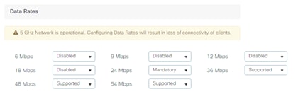
Rogue Location Discovery Protocol
If the Rogue Location Discovery Protocol (RLDP) feature is needed, use it only with monitor mode APs, to prevent performance and service impacts to the wireless network:
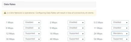
On the CLI, use this command:
C9800(config)# wireless wps rogue ap rldp alarm-only monitor-ap-only
Note: RLDP is supported only on 802.11ac Wave 1 APs. Please check the AP feature matrix for updates.
Rogue Notifications and Telemetry
The Catalyst 9800 has aggressive rogue notification thresholds by default; in certain deployments where RF changes frequently, this may result in the notification receiver (e.g., Cisco Catalyst Center) being overwhelmed by too many messages.
The minimum RSSI detection value recommended is -75 dBm and the minimum transient time is 120 (which is the default).
C9800(config)#rogue detection min-rssi -75
C9800(config)#rogue detection min-transient-time 120
The recommendation is to change the threshold for rogue AP and clients RSSI deviation notification to a higher value than zero (default). Use the following command:
C9800(config)#wireless wps rogue ap notify-rssi-deviation 10
C9800(config)#wireless wps rogue clients notify-rssi-deviation 10
The recommended value is 10 or higher.
Rogue contention can cause severe network disruption depending on the deployment type, AP model and RF environment, please use it with extreme care. Check your local regulations as it might have legal implications in some countries.
This section presents the recommended settings for high availability.
High availability (HA) with stateful switchover (SSO) is a feature supported on all versions of Cisco Catalyst 9800 Series software and all form factors, including the C9800-CL. The SSO feature allows a pair of controllers to act as a single network entity, working in an active/standby scenario. All configuration and AP and client states are synced between active and standby. HA SSO ensures that wireless clients will not have to reconnect and reauthenticate in case of a failure on the current active controller. Whenever allowed by the controller hardware type in use, it is advisable to take advantage of the HA SSO feature, to reduce any possible downtime in case of failure.
In Cisco IOS XE release 17.1 and higher, the C9800 supports the use of the Redundancy Manager Interface (RMI), which allows you to support the following features:
● Gateway check
● Dual active detection
For this reason, 17.1 and higher is the recommended release for C9800 HA SSO. Figure 1 shows the supported topologies.
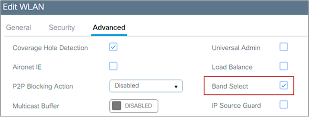
The RP link can be connected using two methods:
● Back-to-back (from WLC A to WLC B directly)
● Using a switch, in this case to prevent a split-brain scenario, ensure this connection uses a different switch than your RMI links.
For more information, see the High Availability SSO Deployment Guide: https://www.cisco.com/c/en/us/td/docs/wireless/controller/technotes/8-8/b_c9800_wireless_controller_ha_sso_dg.html
Note: On the Cisco Embedded Wireless Controller (EWC) on Catalyst Access Points, the HA implementation is slightly different: An active controller and a standby controller are running simultaneously on two Cisco Catalyst 9100 Access Points, so if the active WLC fails, the standby will automatically take over without user intervention. The switchover time is less than 10 seconds but is not stateful, and the controller services will take this time to come back up. Since the EWC operates in FlexConnect local switching mode, the same as with Mobility Express in AireOS, the client traffic is not affected during switchover.
The wireless mobility MAC is the MAC address used for mobility communication. In an SSO scenario, ensure that you explicitly configure the wireless mobility MAC address; otherwise, the mobility tunnel will go down after SSO. The mobility MAC address for the SSO pair can be configured either:
● Before forming the SSO pair on each standalone controller. This is recommended before software release 16.12.3.
● On the active controller once the SSO pair is formed.
To configure the mobility MAC address, you can use the GUI:
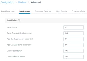
Once you’ve entered the address, click Apply.
Note: The MAC address on the GUI is automatically derived from the wireless management interface, but you can use any other valid MAC address.
In the CLI, use the following command:
C9800#wireless mobility mac-address <MAC>
SSO HA with C9800-CL and vMware vMotion
vMware vSphere vMotion is a zero downtime live migration of workloads from one server to another. This feature can be leveraged for the C9800-CL as well.
If you want to use vMotion on a C9800-CL configured in SSO pair, you need to be aware of the following caveats:
● Due to a current limitation with ESXi switch for Virtual Guest Tagging (VGT mode), there might be an extended data outage during vMotion. As a workaround, you need to initiate traffic (i.e., a continuous ping) from the 9800-CL to update the MAC address in the table on the physical switch connected to the server. The limitation is documented here: https://kb.vmware.com/s/article/2113783?lang=en_US.
● If using local storage, this should be Solid State Drives (SSD) or Hard Disk Drives (HDD) in RAID 0 configuration
● If using remote storage, i.e., Network File System (NFS) or Storage Area Network (SAN), you need to have minimal latency (< 10ms), and i’'s recommended to connect over 10 Gbps link
● vMotion and Snapshot are not supported with SR-IOV interfaces
● It’s not recommended to do vMotion on both Active and Standby at the same time
Note: As of release 17.6, the vMotion feature equivalent for HyperV and KVM have not been validated.
Before forming the SSO pair, make sure:
● The RP ports are connected, either directly or through a dedicated L2 network, before you turn on HA SSO. You can connect either the fiber SFP or ethernet RJ-45 port. The fiber SFP HA connectivity takes priority over RJ-45. If SFP is connected when RJ-45 HA is up and running, the HA pair reloads.
● When connecting the RP ports directly, back-to-back, Cisco recommends using a copper cable with a length less than 30m (100ft). If you need to go beyond 30m (100ft), it’s recommended to connect the RP ports using a fiber cable.
● Both boxes are running the same software and are in the same boot mode (install mode is the recommended one).
● For physical appliances, use same exact hardware type (for example, you cannot pair a C9800-L-C with a C9800-L-F)
● For the C9800-CL, also pick the same scale template (large, medium, or small) on both virtual machines.
● Before forming an HA pair, it is recommended to delete the existing certificates and keys in each of the C9800 which were previously deployed as standalone. This is to avoid the risk that the same trustpoint is present on both WLCs but with different keys. This could cause issues after a switchover.
● Set the keep-alive retries to 5 (this is the default beginning with release 17.1).
● Set the higher priority (2) on the chassis you want to be the active WLC.
The following is an example of the settings for the box that will become the active controller:
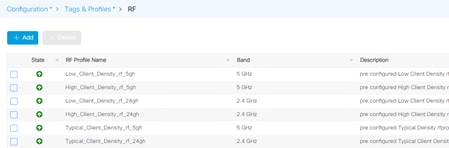
Returns & Replacements (RMA) replacement procedure for SSO pair
If one of the boxes in a SSO pair fails and must be replaced, Cisco recommends you follow this procedure to put the device back in the cluster while avoiding any disruptions to the wireless network:
Physically disconnect the failed box and send it for RMA
1. Make sure that the active WLC is configured with a higher chassis priority (= 2)
2. When you receive the new box, before you connect it to the network and to the existing C9800, please configure the basic parameters offline: login credentials, IP connectivity, and redundancy configuration, including RMI if it applies. Remember to set the chassis priority to 1 so when SSO pair is formed, this box will become the standby and will not disrupt the existing active WLC
3. Save the configuration on the new box and power it off
4. Physically connect the new C9800 to the network (uplink and RP ports)
5. Power on the new box
6. The box will boot up, the SSO pair will be formed again, with the new box going to standby hot state.
In this section you can find general recommendations for building a stable and quality RF design, which is the foundation of a stable wireless network.
For any wireless deployment, always do a proper site survey to ensure adequate service levels for your wireless clients and applications. Keep in mind that each application has different requirements: voice deployments have stricter requirements than data services in terms of latency and jitter; location-based deployments require a denser deployment of APs to be able to triangulate each client position; new IoT applications might impose stringent requirements for latency, etc.
RRM is a great tool, and features like Dynamic Channel Assignment (DCA) and Transmit Power Control (TPC) can help automatically set the best channel and power plan but remember: RRM cannot correct a bad RF design. The site survey must be done with devices that match the power and propagation behavior of the devices to be used on the real network. Ideally, the actual device model and operating system/firmware versions should be used in the same condition and orientation that will be used in the live network. For example, do not use an older 802.11b/g radio with an omnidirectional antenna to study coverage if the final network will use more modern dual radios for 802.11a/b/g/n and 802.11ac/ax/be data rates. The site survey should match the AP model that you are going to install. The AP should be at the orientation and height that will be typical of the final installation. The data rates on the AP should be set to the rates required by your applications, bandwidth, and coverage requirements. If the primary objective of the network design is for each area of coverage to support 30 users at 5 GHz with 9 Mbps of data rate, perform a coverage test with the primary network device with only the 5-GHz data rate with 9 Mbps enabled. Then measure the -67 dBm received signal strength indicator (RSSI) on the AP for the test network client during active data traffic between the AP and client. High-quality RF links have good signal-to-noise ratios (SNRs) of 25 or better and low channel utilization (CU) percentages. RSSI, SNR, and CU values are found on the WLC’s client and AP information pages.
You must carefully plan the process to disable or enable data rates. If your coverage is sufficient, it is a good idea to incrementally disable lower data rates one by one. Management frames such as ACK or beacons are sent at the lowest mandatory rate (typically 1 Mbps), which slows down the whole throughput, as the lowest mandatory rate consumes the most airtime. Try not to have too many supported data rates so that clients can down-shift their rate faster when retransmitting. Typically, clients try to send at the fastest data rate. If a frame does not make it through, the client will retransmit at the next lowest data rate and so on until the frame goes through. The removal of some supported rates helps the clients that retransmit a frame to directly down-shift several data rates, which increases the chance for the frame to go through at the second attempt.
Things to remember when considering the data rate settings:
● Beacons are sent at the lowest mandatory rate, defining roughly the cell size.
● Multicast is sent at the lowest mandatory data rate selected.
● Do you really have 802.11b clients in your network? If you don’t, consider disabling the 802.11b data rates (1, 2, 5.5, and 11) and leaving the rest enabled.
● If you are designing for a hotspot, enable the lowest data rate, because the goal is to have coverage gain versus speed.
● Conversely, if you are designing for a high-speed network and for capacity, with already good RF coverage, disable the lowest data rates.
● Traffic Specification (TSPEC) and Call Admission Control (CAC) require 12 Mbps to be enabled.
Here are general recommendations regarding data rates, but be careful since these are generic, use the previous list to understand if they apply to your network:
· Disable all 11b rates, unless needed
· Use 6 Mbps mandatory where range is prioritized over througput (e.g. outdoors)
· Use 12Mbps mandatory as a default starting point for most networks
· Use 24Mbps mandatory for well-designed high-density networks
· Disable all rates below the mandatory rate
The following configuration serves only as an example and should not be viewed as a strict guideline for every design. These changes are sensitive and heavily dependent on your RF coverage design. To change the data rates, go to Configuration > Radio Configuration > Network and then click on the 5 GHz tab:
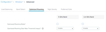
And then the 2.4 GHz tab:
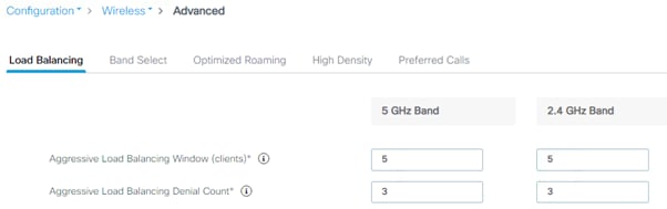
The same applies for the 6 GHz tab.
Cisco recommends limiting the number of service set identifiers (SSIDs) configured on the controller. You can configure 16 simultaneous WLANs/SSIDs (per radio on each AP), but as each WLAN/SSID needs separate probe responses and beaconing, transmitted at the lowest mandatory rate, the RF pollution increases as more SSIDs are added. Also, some smaller wireless stations such as PDAs, Wi-Fi phones, and barcode scanners cannot cope with a high number of basic SSIDs (BSSIDs) over the air. This results in lockups, reloads, or association failures. It is recommended that you have one to three SSIDs per radio band for an enterprise and one SSID per radio band for high-density designs. These applies to all frequencies, 2.4 GHz, 5GHz and 6 GHz. By using the AAA override feature, you can reduce the number of WLANs/SSIDs while assigning individual per-user VLAN/settings in a single-SSID scenario. Enter this command to verify the SSIDs:
C9800#sh wlan summary
Number of WLANs: 3
ID Profile Name SSID Status Security
---------------------------------------------------------------------------1 employee employee UP [WPA2][802.1x][AES]
2 guest guest UP [open],[Web Auth]
3 voice voice UP [WPA2][802.1x][AES]
The 2.4-GHz band is frequently under higher utilization and can suffer interference from Bluetooth devices, microwave ovens, and cordless phones as well as co-channel interference from other APs because of the 802.11b/g limit of three nonoverlapping channels. To prevent these sources of interference and improve overall network performance, you can configure band selection on the controller. Here’s what you should know:
● Band select is configurable per WLAN and is disabled by default.
● Band select works by regulating probe responses to clients. It makes 5-GHz channels more attractive to clients by delaying probe responses to clients on 2.4-GHz channels.
● Do not use band select if you will deploy voice or video services (any interactive traffic), as it may impair roaming performance on some client types.
Most newer clients prefer 5-GHz by default if the 5-GHz signal of the AP is equal to or stronger than the 2.4-GHz signal. This means that on deployments with newer client types, band select may not be necessary. In general, dual-band clients will start scanning on the same band where they first associated. Band select will impact the initial scan, steering clients toward 5 GHz, and so, if the client initially joins the 5-GHz band, it is more likely to stay there if there are good power levels on 5 GHz. To enable this feature, go to the Advanced tab in the WLAN configuration:
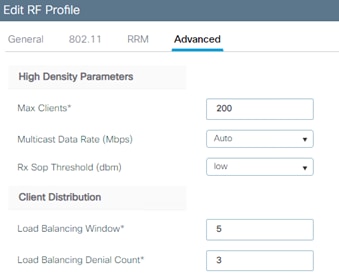
There is no general reason to change the default settings, but if you need to tweak the band select operations for a specific environment, do so here:
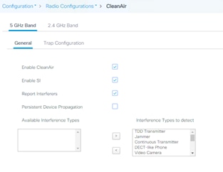
With the introduction of Wi-Fi 6E, a new frequency is now available. This new frequency is 6 GHz, depending on the country the bandwidth available is different. Below you can find some considerations on how to design for this new frequency.
Check the dedicated guide on how to migrate to 6 GHz and Wi-Fi 7 with Cisco Wireless: https://www.cisco.com/c/en/us/support/docs/wireless/catalyst-9800-series-wireless-controllers/223061-migrate-to-wi-fi-7-and-6ghz.html
Free Space Path Loss (FPSL): is the decrease in power density of an electromagnetic wave as it propagates through space. Free Space refers to the fact that there are no obstacles, there is line-of-sight between emitter and receiver. Path loss in the first meter is on average 2dB higher at 6 GHz vs. 5 GHz. After that, the 6 dB rule applies: doubling the distance results in a 6 dB loss, regardless of the frequency.
Cell size considerations: at 6 GHz at the same power level, the 6 GHz cell is smaller than the 5 GHz cell. Due to physics of electromagnetism, the path loss in 6 GHz is higher than in 5 GHz. Here is a graph that shows it.
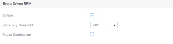
Absorption/reflectance: 6 GHz will be attenuated more through wall or other surfaces.
Noise floor at 6 GHz is much lower than 5 GHz, at least for some time since there is not that many interference in 6 GHz.
Downstream (from AP to client) / Upstream (from client to AP): as it happens with 2.4 GHz and 5 GHz, in 6 GHz expect that the upstream will be your cell limiting factor.
Coverage type: today 6 GHz can only be used indoors, except in the US/Canada where it can be used with Automatic Frequency Coordination (AFC). This is changing, eventually more countries will be supported when regulatory bodies approve it.
AP antenna patterns at 6 GHz are similar to 5 GHz, just a bit “shorter” due to path loss as explained above. AP coverage between 5 GHz and 6 GHz will be similar, especially in open spaces but it does require to compensate with power > 3dB higher in 6 GHz.
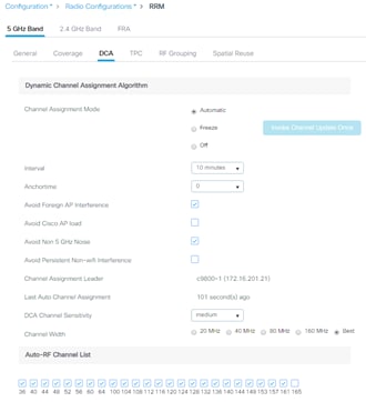
Considerations about deployments
For existing deployments where a refresh is due, one might consider a 1:1 AP replacement of APs. To give some guidance, when the cell size is between 140 and 190 m2 with 3-4 m ceiling height:
● If the average power level is between 3 and 4, then 1:1 AP replacement is possible. A similar coverage level between 5 and 6 GHz will be obtained.
● If the average power level is between 1 and 2, then additional APs will be required, around 10 to 20% extra access points.
For new deployments, a site survey is recommended, leverage the site survey mode on Cisco Wi-Fi 6E/7 APs.
Mixing Wi-Fi 6E, Wi-Fi 7 APs and older generations in the same area is not recommended. As always the recommendation has been to avoid “salt & pepper” design if you can.
High throughput consists of parameters that are designed to improve the rate at which data is successfully delivered over a radio network.
If you want to enable Wi-Fi 7 (802.11be) in your network, you must select the “Enable 11be” check box.
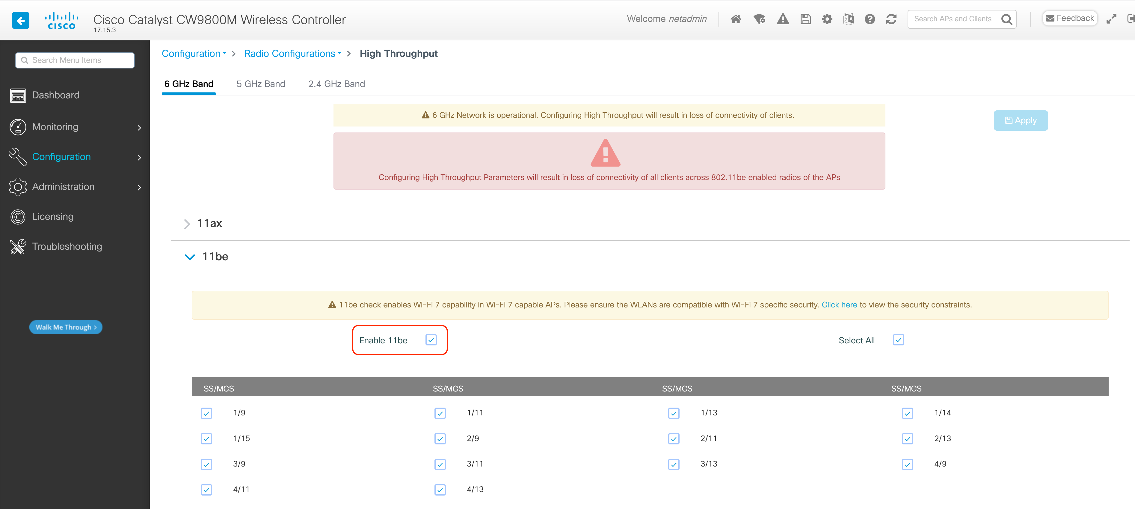
RF profiles are the main mechanism to customize the RRM and RF parameters for a given set of access points. With the C9800, there are two RF profiles, one for each band, and these are assigned to the AP through the RF tag. The C9800 has six default RF profiles (three for each band), and the Typical one is the default:
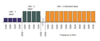
You can change one of the defaults or create a custom parameter. There are many RF parameters that can be customized within an RF profile: channel selection, data rates, RRM settings (DCA, TPC, CHD), RX-SOP thresholds, and more. Here are some general recommendations:
● Set the desired TPC threshold on the RF group, based on the AP density and installed height. For large deployments, there can be significant variations in the RF environment, so it is important to properly adjust TPC to ensure optimal coverage in each location.
● Together with transmit power, data rates are the primary mechanism to influence the client roaming behavior. Changing which is the lowest mandatory rate can modify when the client may trigger a new roam, which is especially important for large open spaces that suffer from sticky client problems.
When setting up RF profiles, try to avoid configuring adjacent AP groups and RF profiles with different DCA channel sets, as this can negatively impact DCA calculations.
User can add a non-supported channel to the RF profile DCA list, even if the channel is not supported in the configured regulatory domain. The recommendation is to always check if the configured channels are allowed in the country domain. There is no impact on network operations since the DCA would not assign the unsupported channels to the APs but, starting release 17.5, the C9800 has added a validation to check if the added channels are allowed.
Aggregated probe response optimization
For large, high-density deployments, it is advisable to modify the default aggregate probe interval sent by access points. By default, the APs will update every 500 ms about the probes sent by clients. This information is used by load balancing, band select, location, and 802.11k features. If there are a large number of clients and access points, it is advisable to modify the update interval to prevent control plane performance issues in the WLC.
To change this setting, use this command:
C9800(config)# wireless probe limit 50 64000
That would set it to 50 aggregated probe responses every 64 seconds, and these are the recommended settings.
Optimized roaming should be disabled because Apple, Samsung, and other modern devices use the newer 802.11r, 802.11k, and 802.11v roaming improvements. This setting is disabled by default, as you can verify in the GUI:
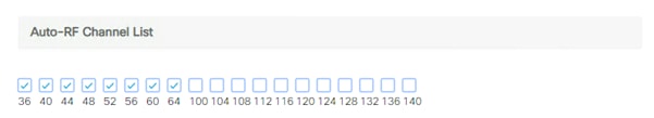
To set it in the CLI, use the following command:
Device(config)# ap dot11 [6ghz | 5ghz | 24ghz] rrm optimized-roam
If load balancing is required, it can be enabled on the WLAN; ensure that the controller has a global window set to five clients or higher, to prevent association errors. This is true for both the 5-GHz and 2.4-GHz bands:
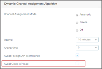
In the C9800 these settings can also be configured per RF profile, which means that the user has the flexibility to assign a load balancing window to only a certain group of APs by assigning those to a specific RF profile and tag:
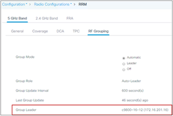
It’s recommended that you use this feature only on good coverage environments as it might have negative impact on voice or interactive video traffic.
To effectively detect and mitigate RF interference, enable Cisco CleanAir® whenever possible. With the addition of the new 6 GHz band CleanAir has now evolved intro CleanAir Pro starting in 17.13. There are recommendations for various sources of interference to trigger security alerts, such as generic DECT phones, jammers, etc. To verify the CleanAir configuration on the different bands, do the following:
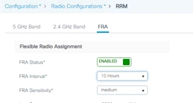
CleanAir in general does not have an impact on network performance, and hence it should be left on. There have been a few customer installations in which a large presence of Bluetooth beacon devices caused some performance degradation. In these cases it’s recommended that you disable CleanAir detection for these types of devices. To do that, use this command:
C9800(config)#no ap dot11 24ghz cleanair device ble-beacon
This feature enables the WLC to do channel changes when sudden and critical RF interference is detected on the APs’ current operating channel, without waiting for the normal DCA process to perform the modification based on RF metrics. It can leverage the CleanAir information, and use it to force a quick reaction time, for situations in which clients will probably be suffering from bad throughput or connectivity issues.
Event-driven RRM (ED-RRM) is not on by default; it’s a good practice to enable it. This is done in the Configuration > Radio Configuration > RRM settings:
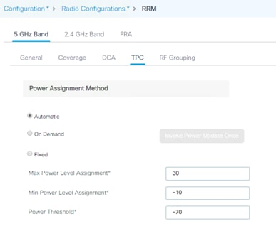
Spectrum Intelligence (SI) is a feature that allows the AP to scan for non-Wi-Fi radio interference on 2.4-GHz and 5-GHz bands. Spectrum intelligence provides basic functions to detect interferences of three types, namely microwave, continuous wave (like video bridge and baby monitor), wi-fi and frequency hopping (Bluetooth and frequency-hopping spread spectrum (FHSS) cordless phone). It is supported on the APs that don’t have a hardware accelerated solution with a dedicated radio:
Since SI is done in software and leverages the client serving radios, Cisco recommends that you disable this feature (done by default starting release 17.6.1) and you consider carefully where and when you want to turn it on.
When a wireless network is first initialized, all participating radios require a channel assignment to operate without interference. Dynamic Channel Assignment (DCA) optimizes the channel assignments to allow for interference-free operation. The C9800 wireless controller does this using the air metrics reported by each radio on every possible channel and providing a solution that maximizes channel bandwidth and minimizes RF interference; interference is from all sources, such as self (signal), other networks (foreign Wi-Fi interference), and noise (everything else).
DCA is enabled by default and provides a global solution to channel planning for your network. Let RRM automatically configure all 802.11a or 802.11b/g channels based on availability and interference. This is the default, but here is the CLI command:
C9800(config)#ap dot11 5ghz rrm channel dca global auto
C9800(config)#ap dot11 24ghz rrm channel dca global auto
All the settings are available on the GUI as well (the example below is for a 5-GHz network):
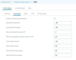
By default, the interval is set to 10 minutes. After your network has been brought up and is stable, it is recommended that you choose a longer interval in hours, for example between 4 and 6 hours.
802.11n can operate in a 40-MHz channel by bonding two 20-MHz channels together, which significantly increases throughput. Not all 802.11n devices support 40-MHz bonded channels, so it’s important to check. 802.11ac/ax/be allows for bonding of 20-MHz channels into an 80-MHz-wide channel for 802.11ac/ax/be usage, and all clients must support 80 MHz. This is not practical for 2.4 GHz, as there are a very limited number of nonoverlapping 20-MHz channels available. However, in 5 GHz and 6 GHz, this can represent a significant increase in throughput and speed, provided you have enough 20-MHz channels available.
Quick overview of channel width:
● 20 MHz: Permits the radio to communicate using only 20-MHz channels. Choose this option for legacy 802.11a radios, 20-MHz 802.11n radios, or 40-MHz 802.11n radios that you want to operate using only 20-MHz channels.
● 40 MHz: Permits 40-MHz 802.11n/ac/ax/be radios to communicate using two adjacent 20-MHz channels bonded together. The radio uses the primary channel that you choose as the anchor channel (for beacons) as well as its extension channel for faster data throughput. Each channel has only one extension channel (36 and 40 are a pair, 44 and 48 are a pair, and so on). For example, if you choose a primary channel of 44, the Cisco WLC would use channel 48 as the extension channel. If you choose a primary channel of 48, the Cisco WLC would use channel 44 as the extension channel. 40 MHz is the recommended width for Apple iOS-focused deployments.
● 80 MHz: Sets the channel width for the 802.11ac/ax/be radios to 80 MHz.
● 160 MHz: Sets the channel width for the 802.11ac/ax/be radios to 160 MHz.
● 320 MHz: only applies to 6 GHz, sets the channel width for the 802.11ax/be radios to 320 MHz. Depending on the country where more or less 6 GHz spectrum is available this might make more or less sense.
● Best: Enables dynamic bandwidth selection, to modify the width depending on environmental conditions. This is the default setting.
When possible, it is recommended to try to leverage as much as possible AI-RRM, this will take of channel-widths. It is known that some devices have a preference towards larger channels widths (80MHz vs 20MHz). If APs next to each other have different channel-widths this might lead to some clients preferring them. When designing try to have if not the same, very similar channel widths in the same areas
In case of multitenant buildings, where channel bonding overlap may happen due to other wireless networks working in the same RF space, you can force the Best option to limit the bonding to 40 MHz:
C9800(config)#ap dot11 5ghz rrm channel dca chan-width width-max WIDTH_40Mhz
For an enterprise scenario a 40 MHz channel width it’s a safe bet and would give you the best compromise between non-overlapping channel availability and performances. In high density or industrial deployments you may need to go to 20 MHz. You should use 80, 160 or 320 MHz only when there are no overlapping networks. Few client devices may not perform properly on 80,160 or 320 MHz, so it should be validated on your environment. Keep in mind that a high throughput requires a higher SNR and when the channel width is increased in 2.4 and 5 GHz the SNR is decreased.
Note: When enabling Best for the first time, a full DCA restart is recommended, using the C9800#ap dot11 5ghz/24ghz rrm dca restart command.
RRM works in conjunction with CleanAir and spectrum analysis, and ED-RRM is an important function to allow a quicker reaction to interference. To improve handling of Wi-Fi interference, rogue severity has been added to the ED-RRM metrics, via a feature called Wi-Fi interference awareness. If a rogue access point is generating interference above a given threshold, this functionality changes channels immediately instead of waiting until the next DCA cycle.
Note: Wi-Fi interference awareness should be used when ED-RRM is enabled. It should be avoided in buildings with a very large number of colocated Wi-Fi networks (multitenant buildings) that are 100% overlapping.
To enable Wi-Fi interference awareness and configure the duty cycle to 80%, go to the DCA tab under Configuration > Radio Configuration > RRM, and go to the Event-Driven-RRM section:

DCA and Dynamic Frequency Selection
Dynamic Frequency Selection (DFS) was created to increase the availability of channels in the 5-GHz spectrum. Depending on the regulatory domain, this can be from 4 to 12 additional channels. More channels imply more capacity. DFS detects radar signals and ensures that there is no interference with weather radar that may be operating on the frequency. Although the 5-GHz band offers more channels, care should be given to the overall design, as the 5-GHz channels have varying power and indoor/outdoor deployment restrictions. For example, in North America, the U-NII-1 channel can be used only indoors and has a restriction of 50 mW maximum power, and both U-NII-2 and U-NII-2e are subject to DFS.
Figure 9: U-NII channels
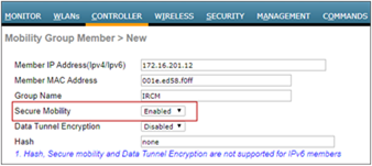
By default, U-NII-2e channels are disabled in the DCA channel list. To check the channels that are being used and add channels, go to the Channel List section:
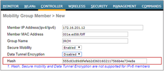
Once you have made selections for channels and channel widths, DCA will manage the channels dynamically and make adjustments as needed over time and changing conditions. However, if this is a new installation, or if you have made major changes to DCA such as changing channel widths or adding new APs, you can restart the DCA process. This initializes an aggressive search mode (startup) and provides an optimized starting channel plan. To determine which WLC is currently the group leader, use these commands:
C9800#sh ap dot11 5ghz group
C9800#sh ap dot11 24ghz group
From the identified group leader, to reinitialize DCA, use these commands:
C9800# ap dot11 5ghz rrm dca restart
C9800# ap dot11 2.4ghz rrm dca restart
Startup mode will run for 100 minutes, reaching a solution generally within 30 to 40 minutes. This can be disruptive to clients, due to lots of channel changes, if significant changes have been made to channel width, number of APs, and so on.
Note: DCA restart should not be performed without change management approval for wireless networks that contain real-time-based applications, especially prevalent in healthcare.
Avoid using this option, as it could trigger too frequent changes in DCA due to varying load conditions. It is disabled by default.
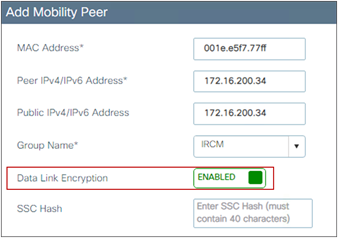
DCA and Flexible Radio Assignment
For Flexible Radio Assignment (FRA) to work properly, it is necessary that the channel change leader (RF group leader) be the same for 2.4, 5 and 6 GHz bands. To check if they are the same navigate to:
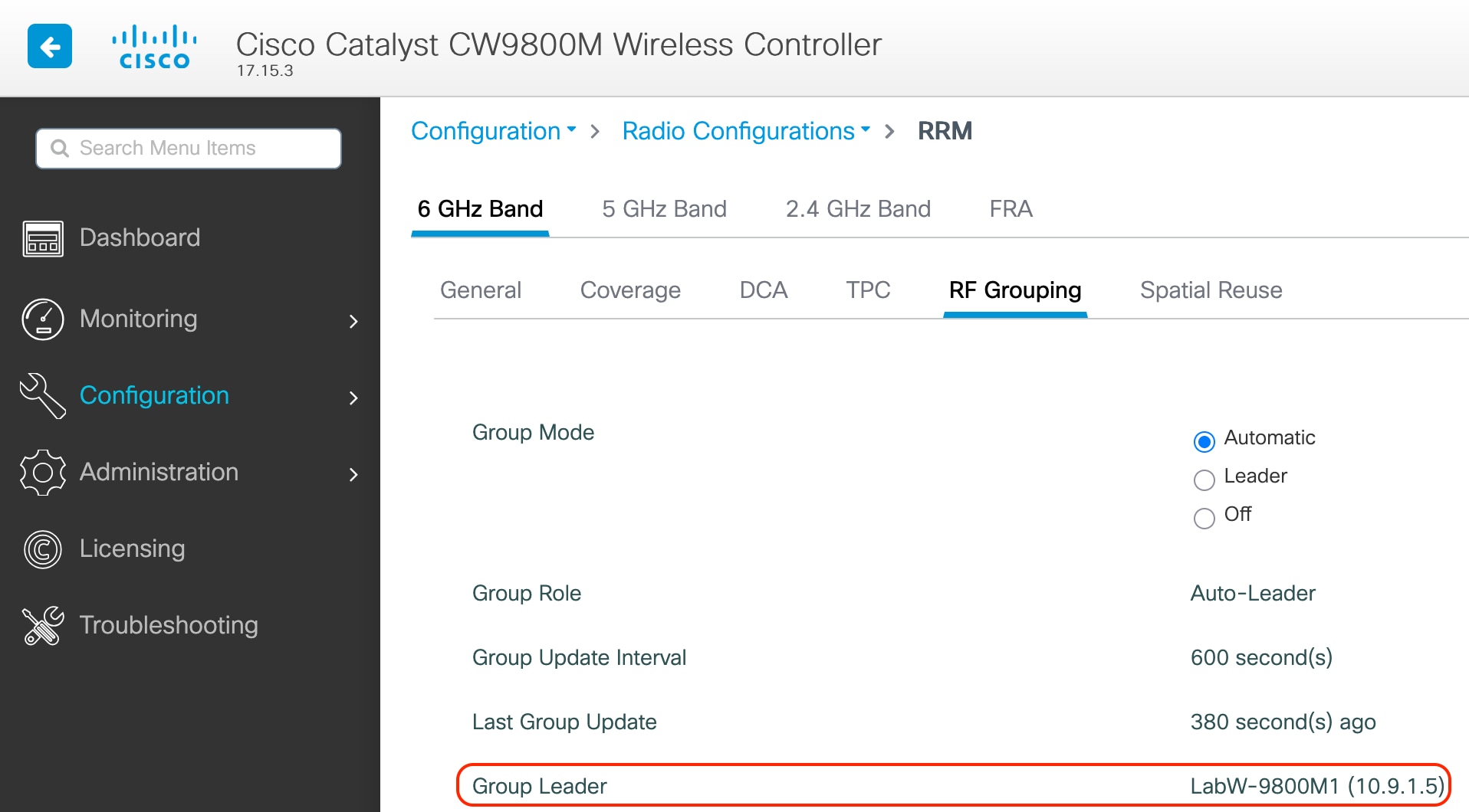
Check in the 3 tabs (2.4 GHz, 5 GHz and 6 GHz) tab to verify who is the group leader for every frequency.
The FRA interval needs to be greater than or equal to the DCA interval, even if FRA is not in use. To modify it, simply set the FRA interval to the desired value, then modify the DCA interval. In the example below, assuming that DCA is set to run every 8 hours, you can set FRA to run every 10 hours:
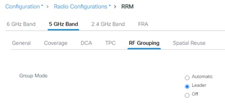
The Catalyst 9800 Wireless Controller dynamically controls the access point transmit power based on real-time wireless LAN conditions.
The Transmit Power Control (TPC) algorithm increases and decreases the power of an AP in response to changes in the RF environment. In most instances, TPC seeks to lower the power of the AP to reduce interference. But in the case of a sudden change in the RF coverage—for example, if the AP fails or becomes disabled—TPC can also increase the power of the surrounding APs. This feature is different from coverage hole detection, which is concerned primarily with clients. TPC provides enough RF power to achieve desired coverage levels while avoiding channel interference between APs. To configure automatic TPC on the 6-GHz, 5-GHz or 2.4-GHz bands, go to Configuration > Radio Configuration > RRM and then select the 6-GHz, 5-GHz Band or 2.4-GHz Band tab:
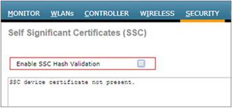
For optimal performance, use the Automatic setting to allow the best transmit power for each radio. While the default values should work for most environments, it is advisable to adjust the TPC thresholds to adapt properly to your RF deployment characteristics.
The controller uses the quality of client signal levels reported by the APs to determine if the power level of that AP needs to be increased. Coverage hole detection (CHD) is run at the single controller, so the RF group leader is not involved in these calculations. The controller knows the number of clients that are associated with a particular AP and the signal-to-noise ratio (SNR) for each client. If a client SNR drops below the configured threshold value on the controller, the AP increases its power level to compensate for the client. The SNR threshold is based on the transmit power of the AP and the coverage profile settings on the controller.
The CHD settings can be found by going to Configuration > Radio Configuration > RRM and then selecting the 6-GHz Band, 5 GHz Band or 2.4 GHz Band tab:
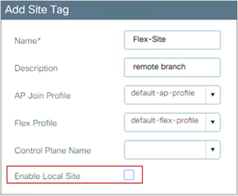
The default settings are recommended for most deployments.
These are the best practices for mobility group configuration.
Ensure that IP connectivity exists between the management interfaces of all controllers. If a controller in the mobility group is permanently down (for replacement, testing, etc.), it is recommended that you remove it from the mobility configuration of all peers.
The mobility group name acts as a discriminator to indicate which controllers share a common cache for fast roaming information (Cisco Centralized Key Management, 802.11r, proactive key caching [PKC], or OKC). It is important to ensure that, if fast roaming is needed between controllers, they share the same mobility group name.
Do not create unnecessarily large mobility groups. A mobility group should contain only controllers that have APs in the area where a client can physically roam—for example, all controllers with APs in a building. If you have a scenario in which several buildings are separated, they should be broken into several mobility groups. This saves memory and CPU, as controllers do not need to keep large lists of valid clients, rogues, and APs inside the group, which would not interact anyway. The C9800 wireless controller, like AireOS, supports a maximum of 24 members in a single mobility group.
Note: Do not confuse mobility groups with mobility domains. The C9800 supports up to 72 wireless controllers in a mobility domain or list. This is used for mobility across multiple mobility groups (this is NOT fast roaming, as that is available only within the same mobility group) and for setting up for foreign anchor peering for guest tunneling.
Inter-controller Layer 2 versus Layer 3 roaming
On the Catalyst 9800, inter-controller Layer 2 roaming occurs when the client VLAN associated to the SSID is the same on both controllers. When the client associates to an access point joined to a new controller, the new controller exchanges mobility messages with the original controller, and the client database entry is moved to the new controller. New security context and associations are established if necessary, and the client database entry is updated for the new access point. This process remains transparent to the user.
Inter-controller Layer 3 roaming occurs when the client VLANs associated to the SSID are different on each controller. Layer 3 roaming is similar to Layer 2 roaming in that the controllers exchange mobility messages on the client roam. However, instead of moving the client database entry to the new controller, the original controller marks the client with an “Anchor” entry in its own client database. The database entry is copied to the new controller client database and marked with a “Foreign” entry in the new controller. The roam remains transparent to the wireless client, and the client maintains its original IP address.
On the Catalyst 9800 Wireless Controller the decision for Layer 2 versus Layer 3 roaming is independent on the client subnet mapped to the client VLAN; only the VLAN matters in deciding the type of roam. This is because Catalyst 9800 doesn’t require a L3 interface to be configured for each client VLAN. If an inter-controller Layer 2 roaming is desired, then it’s user’s responsibility to make sure that the network is configured so that the same IP subnet is associated to the same VLAN on both wireless controllers.
Note: This is different from AireOS, where Layer 2 roaming happens if the client VLAN and the associated subnet are the same on both wireless controllers.
Reduce the need for inter-controller roaming
When implementing AP distribution across controllers in the same mobility group, try to ensure that all access points in the same RF space belong to a single controller. This will reduce the number of inter-controller roams required. A “salt and pepper” scenario (in which APs from different controllers cover the same RF space) is supported, but it is a more expensive process in terms of CPU and protocol exchanges compared to having a single controller per RF space.
Inter-release controller roaming
Cisco supports roaming between controllers running different Cisco IOS XE software versions, but in general, it is advisable to use equal code across the controllers in the same mobility group to ensure consistent behavior across the devices. For more information on what software versions support interoperability, check:
Cisco supports inter-release controller roaming (IRCM) between the Catalyst 9800 and AireOS wireless controllers. This is important to ensure seamless mobility during brownfield and migration scenarios. For details, review the Cisco Catalyst 9800 Wireless Controller–AireOS IRCM Deployment Guide:
Migration from AireOS WLC to C9800
As you design for a migration between AireOS deployment and the new C9800 wireless network, there are some best practices to consider. IRCM guidelines are provided earlier in the Mobility section.
All the roaming between the C9800 and AireOS controllers is Layer 3 roaming. This means that no matter what VLAN the SSID is mapped to on each WLC, the client will always be anchored to the first WLC it joins. In other words, the point of attachment to the wired network doesn’t change with roaming, even if the VLAN on the wired side is the same on both WLCs. We recommend using different VLAN IDs between AireOS and C9800 to avoid any issues.
In the migration design phase, when defining a common SSID for roaming, use a different VLAN ID and subnets on the Catalyst 9800 and on the AireOS WLC.
As a result, clients will get a different IP, whether they join the first Catalyst 9800 or AireOS; seamless roaming is guaranteed either way because the client will always keep its IP address on the VLAN/subnet it joined first.
This might not be possible in the following instances because:
● The customer is not willing to change the subnet design to add another VLAN/subnet for clients that join the newly added Catalyst 9800. This might also involve changes in the AAA and firewall settings.
● The customer leverages public IP subnets so they do’'t have another spare subnet to assign to clients on the same SSID
● The customer is using static IP for wireless devices
When you have to use the same VLAN/subnet on both the Catalyst 9800 and AireOS, then is recommended to use the following releases:
● Cisco IOS XE code: Release 16.12.4a or 17.3.2 and above
● AireOS code: Release 8.5.17x, which is the seventh maintenance release (expected in January 2021) or Release 8.10.142 and above
Mobility groups and Secure Mobility
The C9800 wireless controller uses a Secure Mobility protocol to build a secure mobility tunnel to the mobility peer. Secure Mobility is based on CAPWAP and by default encrypts all the control plane communication via DTLS. In order to set up a tunnel between the C9800 and AireOS, you need the right AireOS IRCM image, and you need to configure Secure Mobility on the AireOS side, as shown below:

The hash is needed only when peering with a C9800-CL. In that case you need to get the hash with the following command:
C9800#sh wireless management trustpoint
Trustpoint Name : ewlc-tp1
Certificate Info : Available
Certificate Type : SSC
Certificate Hash : 555c83c89d8fefab2d3601602117566b4e734e8e
[snip]
Copy and paste the certificate hash into the AireOS mobility peer configuration:
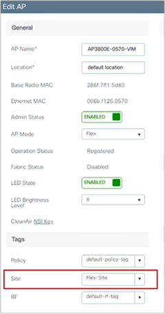
Data link encryption (encrypting client data traffic between controllers) is optional and is recommended if the tunnel is built on top of a nontrusted network. It is disabled by default, and if enabled, it has to be done on both sides. On AireOS:
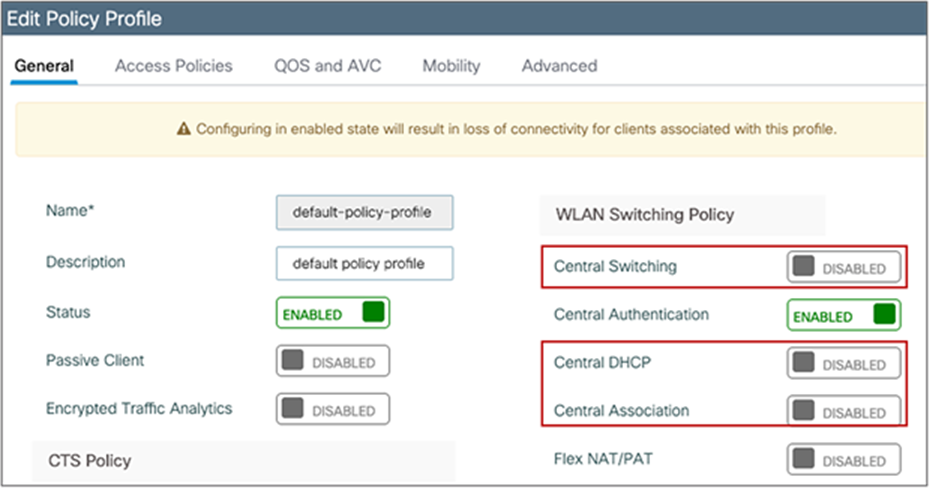
and on the C9800:
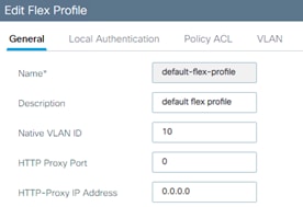
As with two AireOS controllers or two C9800 controllers, the group name must match if you want to create a mobility group for supporting seamless mobility. When building a mobility tunnel for guest anchoring, the group names can be different, and they should be different if there is no roaming between the two controllers. The C9800 does not advertise anchored SSIDs on local APs on a guest anchor. Hence, roaming from foreign to anchor is not possible.
An RF group is a logical collection of wireless controllers that coordinate to perform RRM functions in a globally optimized manner, on a per-radio network basis. Separate RF groups exist for 2.4-GHz,5-GHz and 6-GHz networks. In order to cluster multiple WLCs into a single RF group, you need to set the same RF Group name. In this case, an RF Leader is elected and the RRM algorithms is expanded beyond the capabilities of a single WLC.
Note: Please always change the RF Group name, and avoid default. This will become mandatory in future versions.
In a migration scenario, where you have AireOS and IOS XE based wireless controllers managing a common RF domain, please follow the guidelines below:
● When forming a single RF group, it is recommended to set the RF leader statically and not relying on the default automatic election. This means that you would have to statically configure the most capable controller to be the leader. Here is the list in priority order:
Table 8. RF group scalability
| Group leader order |
Maximum APs |
Maximum AP/RF Group |
| 3504 |
150 |
500 |
| C9800-L |
250 |
500 |
| C9800-CL (Small) |
1000 |
2000 |
| 5520 |
1500 |
3000 |
| C9800-40 |
2000 |
4000 |
| CW9800M |
3000 |
6000 |
| C9800-CL (Medium) |
3000 |
6000 |
| 8540 |
6000 |
6000 |
| C9800-CL (Large) |
6000 |
12000 |
| C9800-80 / CW9800H1 / CW9800H2 |
6000 |
12000 |
● If you have an existing 5520 deployment and you add a C9800-40, you want the IOS XE based controller to become the leader. You can do that on the GUI by configuring the C9800-40 as the RF leader; this is under Configuration > Radio Configurations > RRM, then select each band (6GHz, 5GHz and 2.4 GHz), go to RF grouping and click on “Leader” and then apply.
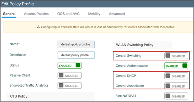
● For very high-density deployment, with a number of APs and clients near to the max scale numbers of the platform, the user should consider configuring each WLC to its own RF group: the advantage is better use of new features and functionalities and better management of newer Catalyst APs that most likely will be deployed only on the Catalyst 9800. It will also help reducing the load on each wireless controller.
Note: If you configure two separated RF Groups, in order to avoid that the APs on the AireOS WLC would show up as rogues on the C9800, please configure the two WLCs in the same mobility group.
Moving APs between an AireOS WLC and the C9800
As you move an AP from an AireOS-based wireless controller to a Cisco IOS XE based one, there are a few considerations to keep in mind.
The first time the AP joins a controller based on a different OS, it will have to download the image and reload, so allow for downtime. After the first time, the AP will have both images in memory (the active and backup images), and you can move the AP back and forth between the two controllers without an additional download.
When moving an AP that is assigned to a certain AP group and a certain RF profile from AireOS to the C9800, this information is lost. You need to make sure that the C9800 is configured with the right profiles and tags and AP mapping, so that when the AP joins it will get the right settings.
Use extra caution when moving an AP from an AireOS-based appliance to a C9800-CL. On the appliance, the AP uses a Manufacturer Installed Certificate (MIC) to join the controller securely. On the C9800-CL, since it’s a VM, there is no MIC, and a self-signed certificate (SSC) is used. In order for the AP to join the C9800-CL, you have two options:
1. Disable SSC validation on the AireOS appliance before moving the AP:
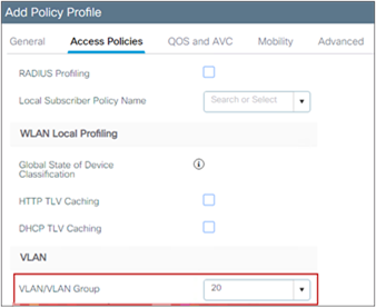
This will make sure that the AP can join any virtual WLC.
2. Configure a token on both controllers before moving the AP.
config certificate ssc auth-token <token> – on AireOS WLC
wireless management certificate ssc auth-token 0 <token> – on the C9800
A token is just a string, and it has to match on both wireless controllers.
Note: When an AP migrates from a Cisco AireOS controller to a Cisco Catalyst 9800 controller, it loses its 802.1X credentials and configuration. To restore them, the AP must join the new Catalyst 9800 controller, which will push the necessary credentials and configuration for authentication on the switchport. You can either temporarily disable 802.1X authentication on the switchport to allow the AP to connect and receive its configuration or use MAC Authentication Bypass (MAB) to provide network access to the AP for staging. After staging, reload the AP or restart 802.1X authentication on the switch to complete the setup.
FlexConnect deployment is optimized for remote sites or branches for a distributed enterprise. Here are some important considerations:
● FlexConnect helps reduce the branch hardware footprint, provides capital and operational expenditure savings, and reduces power consumption by eliminating the need for a local controller.
● The wireless controller function is consolidated at the data center site and provides easy and centralized IT support. FlexConnect is ideal when the customer has a cookie-cutter configuration for multiple locations, as everything is managed centrally.
● FlexConnect is designed for working across a WAN and provides survivability against WAN failures and reduced WAN usage between the central and remote sites.
● For FlexConnect APs, the control plane is always centralized to the central WLC, but the data plane is flexible: the client traffic can be either locally switched at the AP or centrally switched at the controller.
Certain architectural requirements need to be considered when deploying a distributed branch office in terms of the minimum WAN bandwidth, maximum round-trip time (RTT), minimum MTU, and fragmentation. These guidelines are captured in the following guide:
Note: As the CAPWAP control traffic between AP and WLC traverses the WAN, it is a good practice to set the quality of service (QoS) on the wired infrastructure to prioritize CAPWAP control channel traffic on UDP port 5246.
With the C9800, in order to configure an AP to operate in FlexConnect mode, you need to properly configure the site tag you assigned to the AP. In other words, you don’t have to set the mode to FlexConnect on the AP itself (as you were doing for AireOS), but simply to assign the AP to a site tag that is configured to be a remote site, and the C9800 will do the conversion automatically. The AP will NOT reboot but will simply go for a CAPWAP restart and join back in less than 30 seconds.
Here is an example of a site tag configured for FlexConnect:
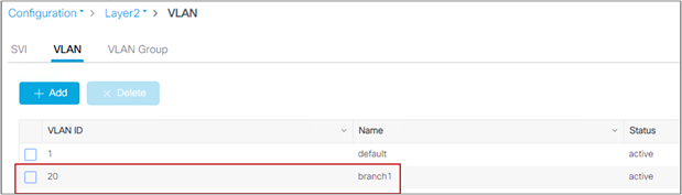
As highlighted in the screen shot above, you need to uncheck Enable Local Site (which is the default), and this will trigger the AP to be converted to Flex mode. Also notice that the default Flex profile will also be selected. This is where you set all the Flex settings and you can use the default or a custom one if you have different settings in every branch.
Let’s look at an example. The AP initially joined in the default site tag, which is by default a local site, and you can see that the AP is in local mode, as expected:
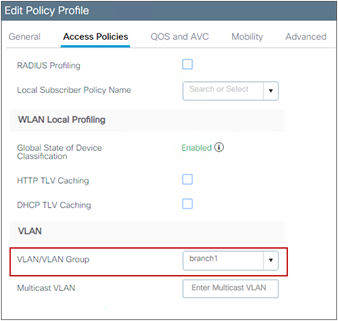
Now assign the AP to the site tag created, the Flex-site one. This can be done by editing the tag assignment on the AP itself:
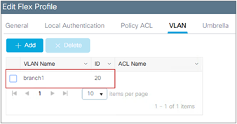
The AP disconnects and comes back in Flex mode, as expected:
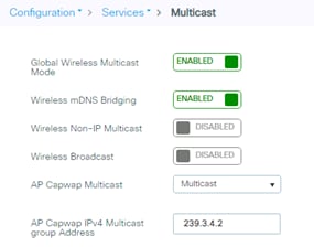
When using FlexConnect, there is a dedicated configuration element named the Flex profile. It contains the remote site-specific parameters. For example, the master and slave AP list, the EAP profiles which can be used for the case where AP acts as an authentication server, local radius server information, VLAN-ACL mapping etc.
Note: When configuring FlexConnect mode, if a VLAN is configured in the Policy profile it must be configured as well in the Flex profile. If this is not done, the WLAN will not be broadcasted.
Here are some recommendations/comments for the FlexConnect:
● The default flex profile does not support DHCP required (see section DHCP Required option for details on what this option means).
● Cisco recommends to always configure a non-default flex profile. By using a non-default flex profile, key caching functionality such as OKC, Fast Transition, etc. will be enabled.
Enable local switching on the WLAN to provide resiliency against WAN failures and reduce the amount of data going over the WAN, thus reducing the WAN bandwidth usage. Local switching is useful in deployments where resources are local to the branch site and data traffic does not need to be sent back to the controller over the WAN link. Recommendations for local switching are as follows:
● Connect the FlexConnect AP to the 802.1Q trunk port on the switch.
● When connecting with a native VLAN on the AP, the native VLAN configuration on the Layer 2 must match the configuration on the AP.
● Ensure that the native VLAN is the same across all APs in the same location and site tag.
Some features are not available in local switching mode, depending on whether the AP is in connected mode (registered to the WLC) or standalone mode (the AP has lost connection to the WLC). Please check the feature availability using the Flex Matrix:
https://www.cisco.com/c/en/us/td/docs/wireless/access_point/feature-matrix/ap-feature-matrix.html
With the C9800, the native VLAN is defined in the Flex profile, as this is a setting for that Flex site. In this example the native VLAN is VLAN 10:
And matches the one configured on the switch:
interface TenGigabitEthernet1/0/3
description to_Flex_AP
switchport trunk native vlan 10
switchport mode trunk
spanning-tree portfast trunk
The local switching attribute and the VLAN that clients would use is defined at the Policy profile, as this is a policy associated to the WLAN. For a locally switched WLAN, just disable central switching and central association on the Policy profile. If the DHCP server is available at the local site, also disable central DHCP:
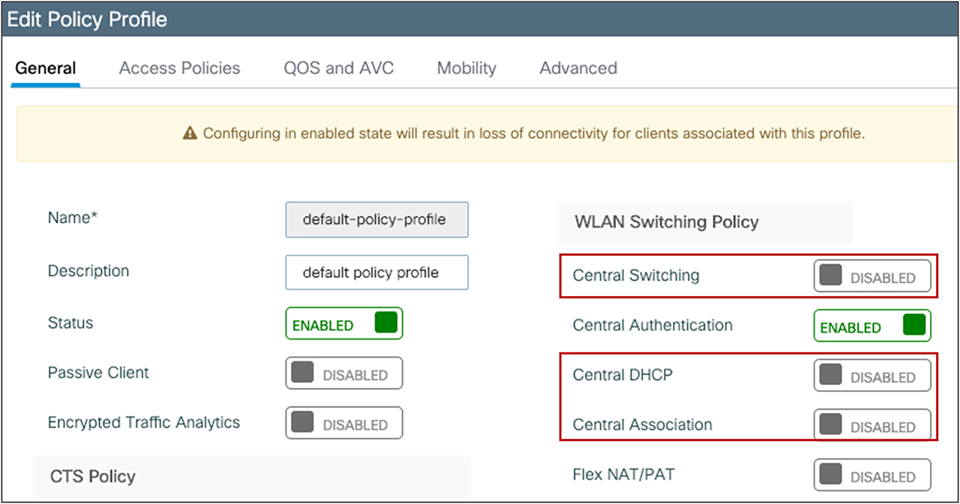
The VLAN on the AP for the locally switched traffic can be configured in two ways:
● Using the VLAN ID (number): Enter the VLAN number directly in the Policy profile. There is no need to define this VLAN on the controller itself, as it’s only for locally switched traffic. This VLAN will be pushed to the APs:
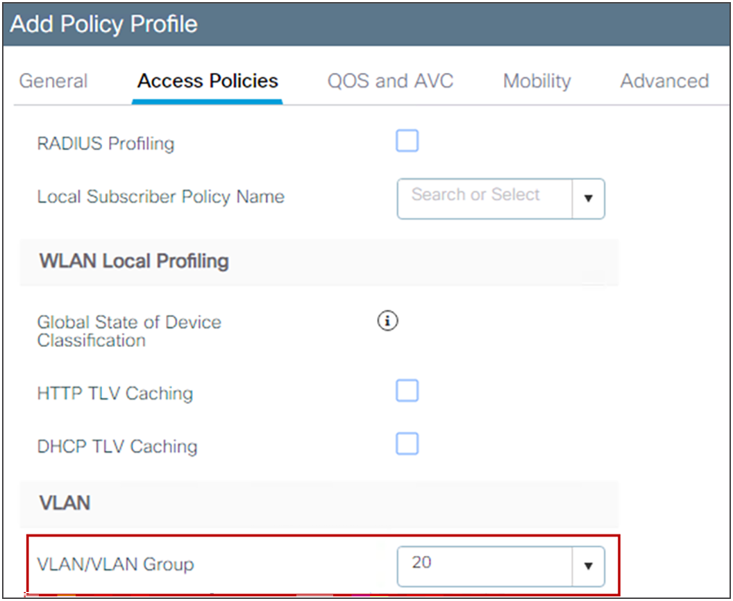
● Using the VLAN name: In this case you create the VLAN name globally on the WLC first and then you must tell the AP which VLAN ID to use for that VLAN name at a specific site. The mapping of VLAN name <> VLAN number needs to be configured under the Flex profile, and in this way the right VLAN ID is pushed to the APs.
Let’s look at an example: VLAN “branch1” is defined first on the controller as a Layer 2 VLAN:
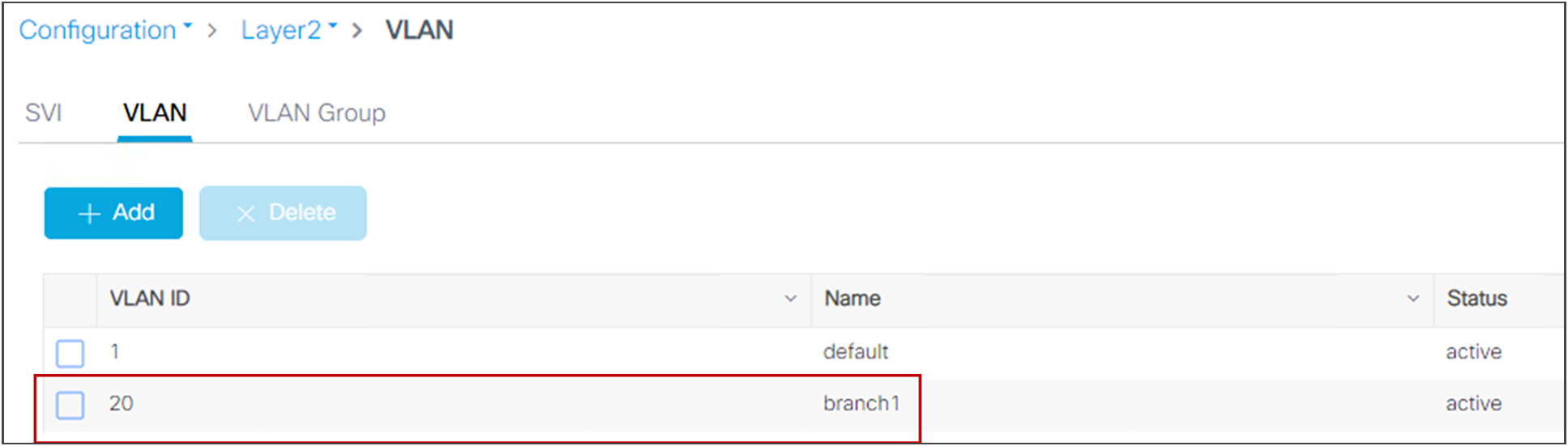
Then you select the VLAN name on the Policy profile:
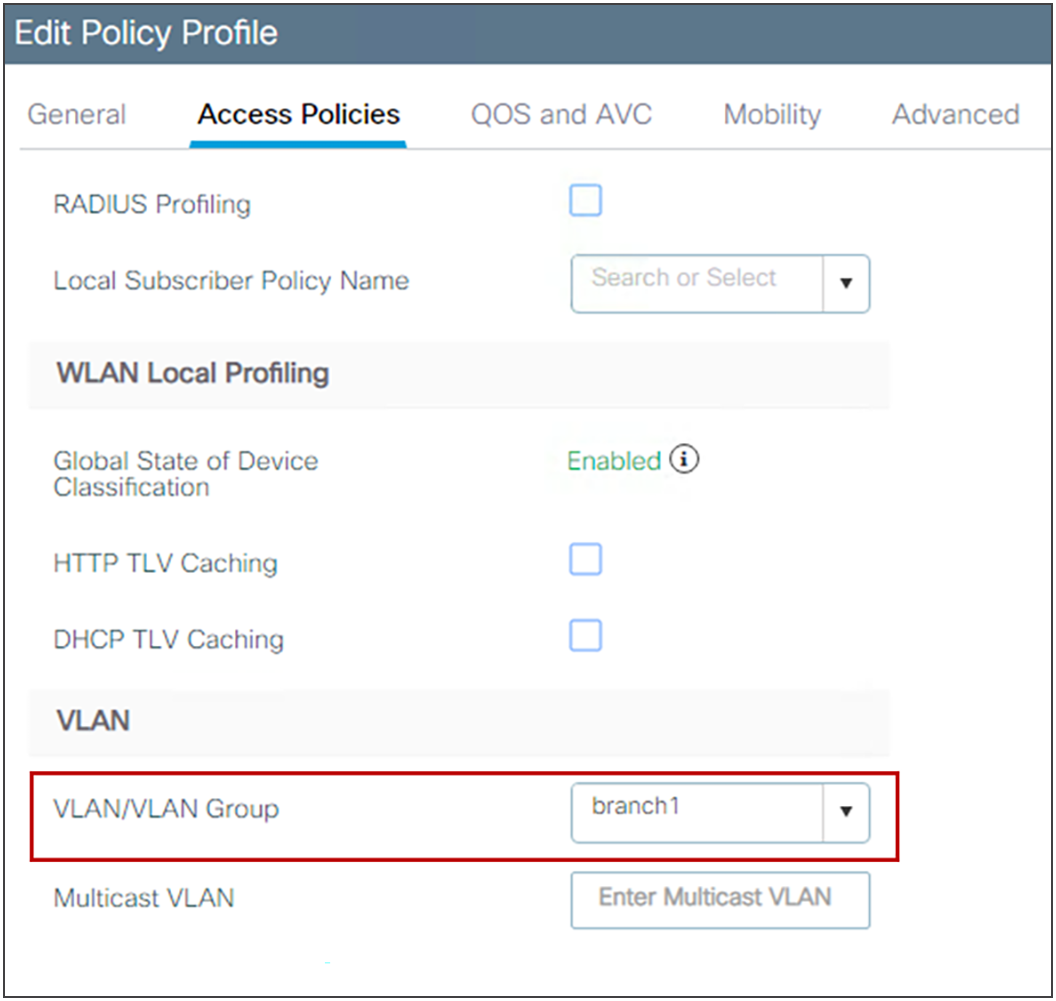
The same VLAN name is mapped to the desired VLAN ID in the Flex profile, under the VLAN tab (in this case it’s the same number, 20):
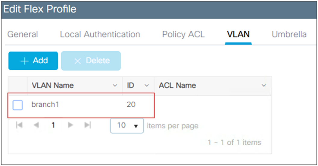
If you have multiple branches and you want to use a different VLAN ID (number) in every branch with the same VLAN name, you can do this by configuring the mapping to the desired VLAN ID in a custom Flex profile assigned to each branch.
Note: A maximum of 16 locally switched VLANs can be mapped to a Flex profile.
Note: The VLAN name to VLAN ID mapping needs to be configured under the Flex profile also to use AAA VLAN override, when a locally switched VLAN is returned via the AAA server.
When the site tag is configured for Flex, meaning that it’s disabled as a local site, it becomes the equivalent of an AireOS FlexGroup. For the C9800, it is important to remember that:
● If seamless fast secure roaming is required, you still have a limit of 100 APs per Flex site tag (the same as AireOS). Starting release 17.8.1 the limit has been increased to 300 APs and 3000 clients, leveraging the “Pairwise Master Key (PMK) propagate” feature which is not enabled by default, see the config guide.
● The client pair master key (PMK) is distributed among the APs that are part of the same Flex site tag. If you roam between two Flex site tags, the client will be forced to do a full reauthentication (the same as AireOS when roaming across Flex groups).
● All the settings for the AP in a Flex site tag are done at the Flex profile level, which is then assigned to the site tag.
From a design perspective, these are best practices you should consider when dealing with FlexConnect site tags:
● With FlexConnect, the site tag defines the perimeter where fast secure roaming is supported. Therefore, you should assign a site tag that equals a roaming domain, where clients are likely to roam. This means that if you have RF leaking between two floors, it is recommended to configure the APs on both floors as part of the same site tag. Of course, keep in mind the 100 AP limit already mentioned.
● You should always use custom site tags with FlexConnect. For the default site tag, fast and secure roaming is not supported.
● You should configure at least one custom site tag per FlexConnect location. (Multiple tags might be needed if you plan to exceed the 100/300 APs limit.) It is also important not to re-use the same site tag across multiple Flex locations (this includes the default-site-tag).
● Starting release 17.3.3, C9800 supports client overlapping IP addresses across different site tags. The site tag in each site should be unique as C9800 uses the combination of site-tag + IP address as a unique ID for the client (called zone-id).
When leveraging the FlexConnect High Scale Mode, which supports up to 300 APs and 3000 clients, be mindful of the following:
● Supporting seamless roaming also requires a single common layer 2 client VLAN, which can lead to problems with spanning tree, big ARP tables, exercise caution there. A multilayer switching design might be necessary.
● When getting close to this scale, consider a dedicated WLC.
Note: Client overlapping IP addresses is only available for Flex deployment in local switching with local DHCP server; for all other deployments (local mode, central switching, central DHCP, etc.), overlapping IPs are still not supported.
There are several features that leverage the concept of a FlexConnect profile and site tag:
● 802.11r Fast Transition (FT), Cisco Centralized Key Management, or OKC fast roaming for voice deployments
● Local backup RADIUS server
● Local EAP
● WLAN-to-VLAN and VLAN-to-ACL mapping
● Cisco Umbrella®
● Cisco TrustSec®
Configure the split tunneling feature in scenarios where most of the resources are located at the central site and client data needs to be switched centrally, but certain devices local to the remote office need local switching to reduce WAN bandwidth utilization. A typical use case for this is the OEAP teleworker setup, where clients on a corporate SSID can talk to devices on a local network (printers, wired machines on a remote LAN port, or wireless devices on a personal SSID) directly without consuming WAN bandwidth by sending packets over CAPWAP. Central DHCP and split tunneling use the routing functionality of the AP.
Split tunneling in the C9800 is configured under the Policy profile. Use the reference in the configuration guide: https://www.cisco.com/c/en/us/td/docs/wireless/controller/9800/17-15/config-guide/b_wl_17_15_cg/m-sniffer-cg.html?bookSearch=true#spilt-tunneling-for-flex
The following limitations apply when deploying split tunneling:
● Split tunneling is supported on 802.11ac Wave 2 and 802.11ax APs starting with Release 17.3.
● Static IP clients are not supported with central DHCP and local split WLANs. So you need to configure DHCP Required under the Policy profile.
Use VLAN-based central switching in scenarios where dynamic decisions need to be made to locally switch or centrally switch the data traffic based on the VLANs returned by the AAA server and the VLANs present at the branch site. For VLANs that are returned by the AAA server and are not present on the branch site, meaning that they have not been mapped to the AP via the Flex profile, the traffic will be switched centrally. In the C9800, VLAN-based central switching is configured at the Policy profile level.
This section provides a quick overview of the Catalyst 9800 Wireless QoS and some key best practices
Wireless QoS for the Catalyst 9800 Wireless Controller
Wireless QoS refers to the capability of a network to provide better service to selected network traffic over the wireless media. The primary goal of QoS is to provide priority, including dedicated bandwidth, controlled jitter and latency (required by some real-time and interactive traffic), and improved loss characteristics.
When considering QoS on Catalyst Wireless, following are important things you need to know:
● As with any other Cisco IOS XE device, QoS features on the Catalyst 9800 are enabled through the Modular QoS Command-line interface (MQC). The MQC is a command-line interface (CLI) structure that allows you to create traffic policies and attach these policies to targets (class-maps, policy-maps, etc.).
● A target is the entity where the policy is applied. The Catalyst 9800 supports two targets: SSID and client.
● In terms of Wireless QoS policies for the Catalyst 9800, you will want to consider the following guidelines:
◦ Wireless targets can be configured only with marking and policing policies
◦ One policy per target per direction is supported
◦ Only one marking action (set DSCP) is supported
◦ Only one set action per class is supported
● Wireless QoS policies for SSID and client may be applied in the upstream and downstream directions. The flow of traffic from a wired source to a wireless target is known as downstream (or egress) traffic. The flow of traffic from a wireless source to a wired target is known as upstream (or ingress) traffic.
● SSID policies: You can create QoS policies on SSID in both the ingress and egress directions. If not configured, a SSID policy will not be applied. The policy is applicable per AP per SSID.
● Client policies: Client policies are applicable in the ingress and egress directions. AAA override is also supported.
● Wireless QoS policies are configured under the Policy Profile.
The main purpose of the Metal QoS profile is to limit the maximum DSCP allowed on the network. The Catalyst 9800 supports four different QoS levels/profiles:
● Platinum/voice – ensures a high quality of service for voice over wireless
● Gold/video – supports high-quality video applications
● Silver/best effort – supports normal bandwidth for clients; this is the default setting
● Bronze/background – provides the lowest bandwidth for guest services
In general, Metal QoS profiles work the same as in AireOS. However, there are some differences in the Catalyst 9800 that you should consider:
● You can apply a Metal profile on both egress and ingress separately.
● On the GUI, you can only set the Metal QoS per SSID. On the CLI you can also configure it on client target.
● On the Catalyst 9800 Metal QoS profiles are not configurable by the user.
● In the Catalyst 9800 the non-matching traffic goes in the default class and it is marked with best effort.
● Per-user and per-SSID bandwidth contracts are configurable via MQC QoS policies.
“DSCP trust” is the QoS model supported by the Catalyst 9800. This means that all the QoS processing (queuing and policies) applied to the wireless traffic within the AP and WLC are based on the client DSCP value and not the 802.11 user priority (UP).
For example, for a centralized switching SSID in the downstream direction (wired to wireless traffic) the AP takes the DSCP value from the received CAPWAP header and uses it for internal QoS processing and mapping (received DSCP > UP > Access_Category). The DSCP value is mapped to the UP value in the frame to the wireless client using the data in Table 9 according to RFC 8325.
Table 9. QoS service classes
| IETF DiffServ Service Class |
DSCP |
802.11 user priority |
802.11 access category |
| Network control |
CS6, (CS7) |
0 |
AC_BE |
| IP telephony |
EF (46) |
6 |
AC_VO |
| VOICE-ADMIT |
VA (44) |
6 |
AC_VO |
| Signaling |
CS5 (40) |
5 |
AC_VI |
| Multimedia conferencing |
AF4x |
4 |
AV_VI |
| Real-time interactive |
CS4 (32) |
5 |
AC_VI |
| Multimedia streaming |
AF3x |
4 |
AC_VI |
| Broadcast video |
CS3 (24) |
4 |
AC_VI |
| Low-latency data (transactional) |
AF2x |
3 |
AC_BE |
| OAM |
CS2 (16) |
0 |
AC_BE |
| High-throughput data (bulk data) |
AF1x |
0 |
AC_BE |
| Best Effort |
DF |
0 |
AC_BE |
| Low-priority data (scavenger) |
CS1 (8) |
1 |
AC_BK |
| Remaining |
Remaining |
0 |
AC_BE |
Note: For DSCP values that don’t map to an entry in Table 9, the Catalyst 9800 will use UP = 0, so traffic is sent as best effort.
In the upstream direction it is recommended to configure the AP to map the inner DSCP client value to the outer CAPWAP header. This is done using the following command under the AP Join profile:
ap profile <name>
qos-map trust-dscp-upstream
If not configured, the AP will use the UP value and map it to the DSCP value described in Table 9. Starting with Release 17.4, the qos-map trust-dscp-upstream is the default setting so that client DSCP is, by default, maintained end to end.
For a detailed configuration guide on QoS, review this configuration guide: https://www.cisco.com/c/en/us/td/docs/wireless/controller/9800/17-15/config-guide/b_wl_17_15_cg/m_wireless_qos_cg_vewlc1_from_17_3_1_onwards.html
Following are some other important considerations and recommendations:
● SSID level policy – is applied per AP to the aggregate traffic for all clients on that SSID
● Client level policy – this is per-client policy. Metal policies (platinum, gold, silver, bronze) cannot be configured per client on the WebUI, but they can be configured via CLI.
● If both SSID and client policies are applied, then the client policy is applied first and then the SSID policy
● QoS policy AAA override is available per client, not per SSID. It is supported for APs in local mode as well as FlexConnect mode. You need to return the policy name as cisco av-pair from the RADIUS server:
● cisco-av-pair = ip:sub-qos-policy-in=MyPolicy
● cisco-av-pair = ip:sub-qos-policy-out=MyPolicy
● QoS policies can also be applied via Auto-QoS. This is a set of predefined profiles that can be further modified by the customer to prioritize different traffic flows. To learn about the different auto-qos profiles and what they do, review this configuration guide: https://www.cisco.com/c/en/us/td/docs/wireless/controller/9800/17-15/config-guide/b_wl_17_15_cg/m_wireless_autoqos_cg_vewlc.html
● For voice SSIDs it is recommended to use the “Fastlane” auto-qos profile (and not the voice profile). Fastlane will trigger the following configuration:
◦ Client QoS policy set to platinum
◦ EDCA parameter set to Fastlane under Radio Configurations > Parameters > 5 and 2.4 GHz bands
◦ The Catalyst 9800’s egress priority queuing is set to prioritize voice and CAPWAP traffic applying the AutoQos-4.0-wlan-Port-Output-Policy service policy
◦ To verify the EDCA settings, use the following command on the AP’s CLI:
sh controllers dot11Radio 1 | begin EDCA
● For Guest SSID, it’s recommended to set the Metal QoS policy to Bronze
● Regarding EDCA settings, remember that these settings are global per radio and not per SSID. There is no single recommended value for all networks, so it is important to test different values. For networks with voice and video traffic, it is a good idea to set the EDCA to “optimized-video-voice”.
● QoS Bi-Directional Rate Limiting (BDRL) policy with AAA override is supported for both local and FlexConnect mode. Please read the QoS BDRL with AAA override on Catalyst 9800 Series Wireless Controllers guide for more details: http://cs.co/BDRL-QoS-example
Verifying the QoS settings on the Catalyst 9800
The main command to use to verify what QoS policy has been configured:
C9800#sh policy-map interface wireless <ssid/client> profile-name <WLAN> radio type <2.4/5GHz> ap name <name> input/output
To verify the client policy:
C9800#show wireless client mac <> service-policy input/output
To verify the EDCA parameters on the AP:
AP#sh controllers dot11Radio 1 | begin EDCA
Note: As with AireOS, QoS policy is applied at the AP for FlexConnect local switching SSIDs and at the controller for centrally switched traffic. It is the same for upstream and downstream directions.
This section provides best practices for enabling multicast applications on your wireless network.
Use multicast forwarding mode for the best performance with less bandwidth utilization for multicast applications when the underlying switched infrastructure supports multicast. Networks with large IPV6 client counts, multicast video streaming, and Bonjour without mDNS proxy may benefit greatly with multicast mode. If the APs are on different subnets than the one used on the WLC’s management interface and AP multicast mode is enabled, your network infrastructure must provide multicast routing between the management interface subnet and all AP subnets; otherwise all multicast traffic will be lost.
To configure multicast-multicast operations on the WLC WebUI go to Configuration > Services > Multicast
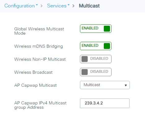
To verify the multicast mode on the controller via the CLI, use the following command:
C9800#sh wireless multicast
Multicast : Enabled
AP Capwap Multicast : Multicast
AP Capwap iPv4 Multicast group Address : 239.3.4.2
AP Capwap iPv6 Multicast group Address : FF08::3:4:2
Wireless Broadcast : Disabled
Wireless Multicast non-ip-mcast : Disabled
AP CAPWAP IPv6 Multicast group Address is needed only if you have APs configured with an iPv6 address; if all the access points are on iPv4 addresses, then the iPv6 multicast address is not needed as an iPv4 multicast CAPWAP overlay can carry both client iPv4 and iPv6 multicast traffic.
Starting with Release 17.2, you can use the following CLI command to verify the status of the capwap multicast tunnel for the APs:
C9800#sh ap multicast mom
AP Name MOM-IP TYPE MOM-STATUS
AP1 iPv4 UP
AP2 iPv4 UP
“MOM” stands for multicast over multicast.
Multicast-forwarding mode is the recommended setting. Use unicast forwarding only for small deployments and when multicast routing support in the network infrastructure is not possible. Unicast forwarding is not supported on the C9800-80, C9800-40, and C9800-CL medium and large template platforms.
The multicast address is used by the controller to forward traffic to APs. Ensure that the multicast address does not match another address in use on your network by other protocols. For example, if you use 224.0.0.251, it breaks mDNS used by some third-party applications.
Cisco recommends that the address be in the private range (239.0.0.0 to 239.255.255.255, which does not include 239.0.0.x and 239.128.0.x, as those ranges will cause a Layer 2 flood). Also ensure that the multicast IP address is set to a different value on each WLC to avoid multicast packet duplication.
If you are using a native iPv6 wireless infrastructures (APs configured with iPv6 address) or a mix of iPv4 and iPv6, then the Multicast group Address needs to be configured with an iPv6 address as well.
Using Internet Group Management Protocol (IGMP) and Multicast Listener Discovery (MLD) snooping may provide additional multicast forwarding optimization, as only APs with clients that have joined the respective multicast groups will transmit the multicast traffic over the air, so this is a recommended setting to have in most scenarios. Always check your client and multicast application behavior, as some implementations may not do IGMP group join, or may not refresh properly, causing the multicast streams to expire.
mDNS (Bonjour Protocol) is a protocol to resolve hostnames to IP addresses within small networks that do not include a local name server. It’s used by clients to discovers services like AirPlay, AirPrint, Googlecast, etc. The protocol leverages UDP IP multicast and it’s limited to a Layer 2 broadcast domain.
In C9800 architecture there are two modes of operations regarding mDNS traffic forwarding: Bridging and mDNS gateway
mDNS Bridging refers to same L2 broadcast protocol packet forwarding. C9800 enables mDNS bridging functionality for packets received on the wired ports and wireless interfaces for each WLAN by default; however, you can disable it per WLAN if needed by just changing the mDNS mode at WLAN settings. If Multicast-Multicast mode is enabled, C9800 bridges each mDNS packet to the AP multicast group configured on the controller so wireless clients can receive it, otherwise, it will create a copy of each mDNS packet received, which is then bridged individually to every single AP via CAPWAP unicast tunnel. Both scenarios, C9800 also bridges the mDNS packets into the wired at the VLAN of the client that originated the mDNS packet. Therefore, mDNS will work in C9800 without special configuration if the devices are on the same subnet. Ideally, it is better to filter mDNS traffic with the use of mDNS Gateway.
The mDNS Gateway service on the C9800 listens for Bonjour services (mDNS advertisements and queries) on wired and wireless interfaces, caches these Bonjour services in an internal database and forwards these mDNS packets between different broadcast domains/VLANs while filtering unneeded services. This way you can have the sources and clients of such services in different subnets, and control mDNS traffic in your network.
The C9800 that acts as mDNS Gateway replies to mDNS queries from clients (for cached services) sourcing these mDNS responses with the use of its IP address for the VLAN assigned to the client asking for the service. This is why all VLANs on the C9800 controller where there are clients that require mDNS/Bonjour services must have a valid IP address configured at the Switched Virtual Interface (SVI).
This requirement is no longer applicable starting release 17.9.1 where the mDNS traffic will be sourced from the WMI interface.
Processing of mDNS packets can be quite resource consuming especially when mDNS gateway is enabled. Specifically, the Apple Continuity Service can be very chatty. In networks where there are a lot of clients and a lot of services being advertised, it’s recommended to consider the following best practices:
● Create your own mDNS service list, and don’t use the default profile so you can decide which services you really need.
mdns-sd service-list <service list name> OUT
no match <service name>
mdns-sd service-list <service list name> IN
no match <service name>
● Configure the mDNS service policy to use Location Specific Services (LSS) to optimize mDNS responses to clients, using the command:
mdns-sd service-policy <name>
location lss
● Configure mDNS transport to be IPv4 or IPv6, not both. IPv4 is recommended:
mdns-sd gateway
transport ipv4
● In very high-density environments, as described above it is also recommended to disable Apple Continuity Service:
mdns-sd service-list <service list name> OUT
no match apple-continuity
mdns-sd service-list <service list name> IN
no match apple-continuity
This section explains the outdoor best practices for design, deployment, and security.
Perform an RF active site survey and estimate the coverage
The outdoor environment is a challenging RF environment. Many obstacles and interferers exist that cannot be avoided. Prior to designing a network, an RF active site survey is the first step to understand your RF environment.
Once the RF active site survey is performed, you must estimate the number of outdoor access points required to meet your network’s design requirement. There are several professional tools in the market available to do this, we always recommend leveraging them to understand how many APs are needed.
Outdoor access points can operate in multiple deployment modes, with each deployment mode meeting a different use case.
● Local mode: This is the best option for an outdoor deployment when mesh is not needed. It provides full feature support and RRM, and allows the 2.4-GHz and 5-GHz radios to be used exclusively for client access. This deployment mode should be used when each access point has a dedicated Ethernet connection.
● Bridge mode: A common option for an outdoor deployment when mesh deployment is desired because a cable connection is not present for all APs. The AP operates either in root access point (RAP) mode, when the wired backhaul is available, or in mesh access point (MAP) mode when the AP uses the wireless backhaul. The wireless client traffic is CAPWAP tunneled to the WLC.
● Bridge-Flex mode: Provides flexible and hybrid operation between mesh and Flex. This is recommended for scenarios in which the APs are separated by a WAN link from the WLC; also this mode is useful when you need to have traffic be locally switched at the AP level and not sent centrally to the controller.
Note: If you want to use an outdoor AP in fabric mode, meaning to broadcast fabric SSID, then local mode is the only mode supported.
Avoid selecting DFS channels for backhaul
If the regulatory domain channel plan allows it, when selecting the backhaul channel for a mesh tree, avoid channels that can be used for radar (DFS channels).
Deploy multiple RAPs in each BGN
When deploying a mesh network, there should be multiple paths for each access point back to a WLC. Multiple paths can be added by having multiple RAPs per mesh tree. If a RAP fails and goes offline, other mesh access points will join another RAP with the same bridge group name (BGN) and still have a path back to the WLC.
For best results, follow these simple recommendations:
● Ensure that RAPs are configured on different channels to reduce or avoid co-channel interference. MAPs will use background scanning to identify each RAP.
● RAPs should be on the same VLAN/subnet to prevent mesh AP address renegotiation on parent change that could delay total mesh convergence time.
● Ensure that MAPs have background scanning enabled, to facilitate new parent discovery.
On the C9800 wireless controller, the mesh configuration can be done at the global level, at the Mesh profile level, and also at the AP level. Using a Mesh profile is useful, as you can group all the desired settings in one place and then apply them to the group of APs by assigning the Mesh profile to the AP Join profile.
The global configuration is found under Configuration > Wireless > Mesh:

On the same page you can click the Profiles tab to define a custom one or change the default Mesh profile.
Another AP-specific configuration can be done by using the ap exec command:
C9800#ap name <NAME> mesh ?
backhaul Configure mesh backhaul
block-child Set mesh block child state
daisy-chaining Set mesh daisy chaining
ethernet Configures Ethernet Port of the AP
linktest Perform a linktest between two APs
parent Set mesh preferred parent mac address
security PSK provisioned key deletion from AP
vlan-trunking Enables vlan trunking for bridge mode AP
Let’s consider a few recommended settings. When operating in bridge mode, each access point should be assigned a bridge group name and preferred parent. This helps the mesh network to converge in the same sequence every time, allowing the network to match the initial design.
The bridge group can be set at the Mesh profile level:
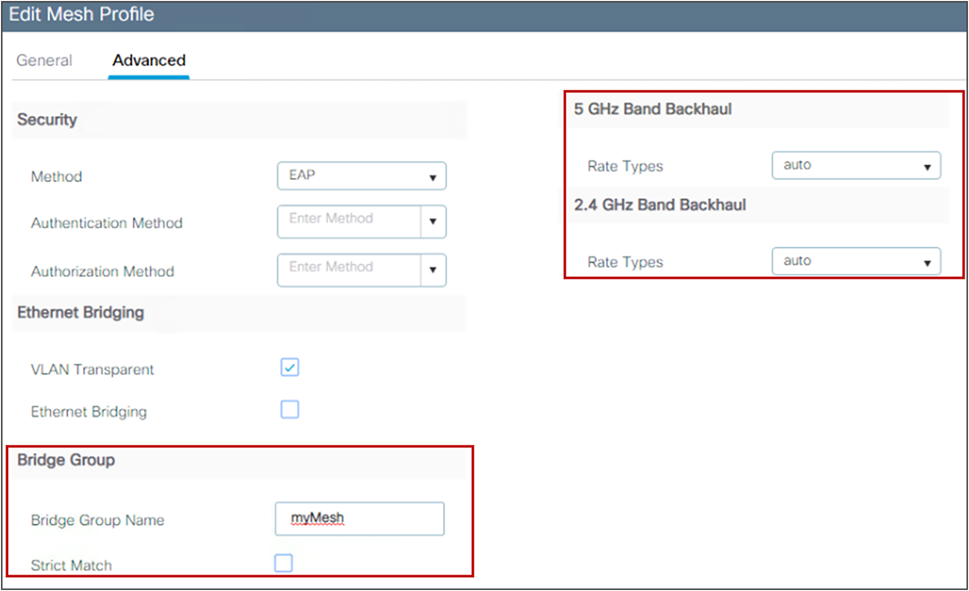
When deploying a mesh network, each mesh node should communicate at the highest possible backhaul data rate. To ensure this, it is recommended that you enable Dynamic Rate Adjustment (DRA) by selecting the Auto backhaul data rate. DRA has to be enabled on every mesh link by enabling it in the mesh Profile, as shown above.
Setting the preferred parent is a per-AP configuration:
C9800#ap name ap-name mesh parent preferred mac-address
To verify, use this command:
C9800#show ap name ap-name mesh neighbor detail
For a mesh network, a backhaul speed of 40 MHz allows the best equilibrium between performance and RF congestion avoidance. To set the channel width per AP, use the following command:
C9800# ap name <AP-name> dot11 5ghz channel width 40
To ensure optimal performance over your mesh network, make sure the backhaul link quality is good. An optimal link quality would be greater than 40 dBm, but this is not always achievable in a non-line-of-sight deployment or in long-range bridges. Cisco recommends that the link SNR be 25 dBm or greater. To check the link SNR, use the following command:
C9800#sh wireless mesh neighbor
If you want to authenticate APs as they join the mesh network, an external RADIUS server should be configured for MAC authentications. This allows all bridge mode access points to authenticate at a single location, thus simplifying network management. For instructions on how to set up authentication, refer to the configuration guide:
https://www.cisco.com/c/en/us/td/docs/wireless/controller/9800/17-15/config-guide/b_wl_17_15_cg/m_mesh_ewlc.htmlTo have the best equilibrium between mesh security and ease of deployment, it is advisable that you enable the Mesh Key Provisioned feature. For more details, see the configuration guide:
The Catalyst 9800 Wireless controller supports streaming telemetry to efficiently stream data to an external collector. The collector further analyzes the data and extracts relevant information for monitoring and troubleshooting. C9800 supports dial-in and dial-out telemetry. With dial-out or “configured” telemetry subscriptions, once the configuration is setup by the user, C9800 will maintain the subscription configuration and send telemetry to the subscriber without needing an active session at the collector. Here is a sample configuration of a telemetry subscription:
telemetry ietf subscription 1011
encoding encode-tdl
filter tdl-uri /services;serviceName=ewlc/wlan_config
source-address <source IP on the C9800>
stream native
update-policy on-change
receiver ip address <collector/subscriber IP> protocol tls-native profile <profile name>
Since 17.6, the C9800 supports maximum 128 concurrent telemetry subscriptions and in 17.15 the limit has been increased to 150. The Catalyst 9800 supports streaming telemetry to one instance, and one instance only, of Cisco Catalyst Center and Cisco Prime Infrastructure (PI). You can have both collectors active at the same time, but you cannot have C9800 streaming telemetry to two different Cisco Catalyst Center collectors, for example. If using an external 3rd party collector, make sure that the number of sessions doesn’t exceed the max supported number.
To show the existing subscriptions you can use the following command
show telemetry ietf subscription all
Telemetry subscription brief
ID Type State Filter type
--------------------------------------------------------
1011 Configured Valid tdl-uri
1012 Configured Valid tdl-uri
1013 Configured Valid tdl-uri
1014 Configured Valid nested-uri
1016 Configured Valid tdl-uri
1051 Configured Valid tdl-uri
Under “State” column you will also know if the subscription is valid.
You can find more information about this in the Catalyst 9800 Programmability and Telemetry Deployment Guide: https://www.cisco.com/c/en/us/td/docs/wireless/controller/9800/technical-reference/catalyst-9800-programmability-telemetry-deployment-guide.html
C9800 Managed by Prime and Catalyst Center
Catalyst 9800 Wireless LAN Controller cannot be simultaneously managed by both Cisco Prime Infrastructure (PI) and Catalyst Center in a read-write fashion. It is possible though to have Prime managing the C9800 for configuration and reporting and use Catalyst Center for Assurance. In a nutshell, only one management platform can be configuring the box and have write access.
Note: Prime is already End of Sale, please consider a replacement. The latest IOS-XE version supported is 17.17. The newest physical appliances CW9800 are not supported.
For more information on how to configure Prime to manage C9800, please use this link: https://www.cisco.com/c/en/us/support/docs/wireless/catalyst-9800-series-wireless-controllers/214286-managing-catalyst-9800-wireless-controll.html
Here what is important to understand: if you have a plan to move to Cisco Catalyst Center as a network management solution, C9800 needs to be removed from Prime Infrastructure first. When C9800 is removed/deleted from PI, all the configuration that was pushed to C9800 at the time of inventory by PI does not get rolled back and these need to be manually deleted from the system. Specifically, the subscription channels established for C9800 WLC to publish streaming telemetry data does not get removed.
To identify this specific configuration:
C9800#show run | sec telemetry
To remove this configuration, run the no form of the command:
C9800(config) # no telemetry ietf subscription <Subscription-Id>
Repeat this CLI to remove each of the subscription identifiers. Repeat this other CLI to remove each of the transform names
C9800(config) # no telemetry transform <Transform-Name>
Refer to these documents for the latest on troubleshooting:
https://logadvisor.cisco.com/logadvisor/wireless/9800/
![]()