- asr901-ecmp-hash-config global-type
- asr901-ecmp-hash-config ipv4-type
- asr901-ecmp-hash-config ipv6-type
- asr901-ecmp-hash-config mpls-to-ip
- asr901-multicast source
- asr901-platf-frr enable
- asr901-platf-multicast enable
- asymmetry-compensation
- bfd all-interfaces
- bfd interval
- channel-group (interface)
- channel-protocol (interface)
- class (policy-map)
- class cem
- clear platform ptp stats
- clock-port
- clock-destination
- clock source (interface)
- controller
- cpu traffic ppp set ip dscp cs
- cpu traffic ppp set mpls experimental topmost
- debug platform tcam error
- debug platform tcam info
- dejitter-buffer
- dmm responder hardware timestamp
- duplex
- efd notify g8032
- encapsulation dot1q (service instance)
- encapsulation dot1ad
- environment-monitor
- esmc mode
- ethernet loopback
- ethernet oam remote-failure action
- idle-pattern
- interface vlan
- interface atm ima
- interface port-channel
- interface range
- ip tos
- l3-over-l2 flush buffers
- l2proto-forward
- load-interval
- mac-flap-ctrl
- match ip dscp
- match vlan
- mtu
- name
- negotiation
- network-clock clear switch
- network-clock eec
- network-clock external hold-off
- network-clock hold-off global
- network-clock hold-off
- network-clock input-source
- network-clock input-source controller
- network-clock output-source system
- network-clock quality-level
- network-clock revertive
- network-clock wait-to-restore
- network-clock wait-to-restore global
- network-clock set lockout
- network-clock switch force
- network-clock switch manual
- network-clock synchronization automatic
- network-clock synchronization ssm option
- offload sampling
- payload-size
- police (percent)
- police (two rates)
- policy-map
- protocol (ATM)
- pseudowire-class
- ptp profile telecom
- ql-enabled rep segment
- qos-config scheduling-mode min-bw-guarantee
- rep block port
- rep platform fast-lsl enable
- rep platform vlb segment
- rep segment
- router isis
- service instance
- service-policy (policy-map class)
- set cos
- set dscp
- set ip dscp
- set ip precedence (policy-map)
- set ip precedence (route-map)
- set ip precedence tunnel
- set ip tos (route-map)
- set network-clocks
- set precedence
- shape (percent)
- shape (policy-map class)
- show asr901 multicast-support
- show atm cell-packing
- show cem circuit
- show cem platform
- show etherchannel
- show ethernet loopback
- show interface port-channel
- show interfaces rep
- show ip vrf
- show mac-address-table
- show network-clock synchronization
- show platform hardware
- show platform ptp state
- show platform ptp stats
- show platform ptp stats detailed
- show platform tcam detailed
- show platform tcam summary
- show policy-map
- show policy-map interface
- show ptp port running detail
- show rep topology
- show table-map
- show xconnect
- snmp mib rep trap-rate
- speed
- synce state master
- synce state slave
- synchronous mode
- table-map
- termination
- transport ipv4
- tune-buffer port
- xconnect logging redundancy
ASR 901 Router Series Command Reference
This chapter contains an alphabetical listing of commands for the Cisco ASR 901 Series Aggregation Services Router.

Note![]() For a general reference for Cisco IOS, see the documentation for Cisco IOS Software Releases 15.1S. The Cisco ASR 901 does not necessarily support all of the commands listed in the 15.1S documentation.
For a general reference for Cisco IOS, see the documentation for Cisco IOS Software Releases 15.1S. The Cisco ASR 901 does not necessarily support all of the commands listed in the 15.1S documentation.
- asr901-ecmp-hash-config global-type
- asr901-ecmp-hash-config ipv4-type
- asr901-ecmp-hash-config ipv6-type
- asr901-ecmp-hash-config mpls-to-ip
- asr901-multicast source
- asr901-platf-frr enable
- asr901-platf-multicast enable
- asymmetry-compensation
- bfd all-interfaces
- bfd interval
- channel-group (interface)
- channel-protocol (interface)
- class (policy-map)
- class cem
- clear platform ptp stats
- clock-port
- clock-destination
- clock source (interface)
- controller
- cpu traffic ppp set ip dscp cs
- cpu traffic ppp set mpls experimental topmost
- debug platform tcam error
- debug platform tcam info
- dejitter-buffer
- dmm responder hardware timestamp
- duplex
- efd notify g8032
- encapsulation dot1q (service instance)
- encapsulation dot1ad
- environment-monitor
- esmc mode
- ethernet loopback
- idle-pattern
- interface vlan
- interface atm ima
- interface port-channel
- interface range
- ip tos
- l3-over-l2 flush buffers
- load-interval
- mac-flap-ctrl
- match ip dscp
- match vlan
- mtu
- name
- negotiation
- network-clock clear switch
- network-clock eec
- network-clock external hold-off
- network-clock hold-off global
- network-clock hold-off
- network-clock input-source
- network-clock input-source controller
- network-clock output-source system
- network-clock quality-level
- network-clock revertive
- network-clock wait-to-restore
- network-clock wait-to-restore global
- network-clock set lockout
- network-clock switch force
- network-clock switch manual
- network-clock synchronization automatic
- network-clock synchronization ssm option
- offload sampling
- payload-size
- police (percent)
- police (two rates)
- policy-map
- protocol (ATM)
- pseudowire-class
- ptp profile telecom
- ptp profile telecom
- ql-enabled rep segment
- qos-config scheduling-mode min-bw-guarantee
- rep block port
- rep platform fast-lsl enable
- rep platform vlb segment
- rep segment
- router isis
- service instance
- service-policy (policy-map class)
- set cos
- set dscp
- set ip dscp
- set ip precedence (policy-map)
- set ip precedence (route-map)
- set ip precedence tunnel
- set ip tos (route-map)
- set network-clocks
- set precedence
- shape (percent)
- shape (policy-map class)
- show asr901 multicast-support
- show atm cell-packing
- show cem circuit
- show cem platform
- show etherchannel
- show ethernet loopback
- show interface port-channel
- show interfaces rep
- show ip vrf
- show mac-address-table
- show network-clock synchronization
- show platform hardware
- show platform ptp state
- show platform ptp stats
- show platform ptp stats detailed
- show platform tcam detailed
- show platform tcam summary
- show policy-map
- show policy-map interface
- show ptp port running detail
- show rep topology
- show table-map
- show xconnect
- snmp mib rep trap-rate
- speed
- synce state master
- synce state slave
- synchronous mode
- table-map
- termination
- transport ipv4
- tune-buffer port
- xconnect logging redundancy
asr901-ecmp-hash-config global-type
To specify the equal-cost multi-path routing (ECMP) hashing algorithm at the global level, use the asr901-ecmp-hash-config global-type command in global configuration mode. To remove this configuration, use the no form of this command.
asr901-ecmp-hash-config global-type {hash-crc16-mode | hash-seed seed-value | hash-xor1-mode | hash-xor2-mode | hash-xor4-mode | hash-xor8-mode | tunnel-mode} add
no asr901-ecmp-hash-config global-type {hash-crc16-mode | hash-seed seed-value | hash-xor1-mode | hash-xor2-mode | hash-xor4-mode | hash-xor8-mode | tunnel-mode} add
Syntax Description
Enables tunnel mode to look into the inner header for tunneled packets. |
|
Command Default
Command Modes
Global configuration (config)#
Command History
|
|
|
|---|---|
This command was introduced on the Cisco ASR 901 Series Aggregation Services Routers. |
Usage Guidelines
This command is used to configure the ECMP hash configurations for improved load distribution of IP traffic. The hash-crc16-mode algorithm is enabled by default for ECMP.
Examples
The following example shows how to configure the ECMP hash configuration on a Cisco ASR 901 router:
Related Commands
|
|
|
|---|---|
asr901-ecmp-hash-config ipv4-type
To specify equal-cost multi-path routing (ECMP) hashing algorithm for IPv4 configuration, use the asr901-ecmp-hash-config ipv4-type command in global configuration mode. To remove this configuration, use the no form of this command.
asr901-ecmp-hash-config ipv4-type {dest-addrs | dest-l4-port | l3-proto-id | outer-vlan | src-addrs | src-intf | src-l4-port} add
no asr901-ecmp-hash-config ipv4-type {dest-addrs | dest-l4-port | l3-proto-id | outer-vlan | src-addrs | src-intf | src-l4-port} add
Syntax Description
Command Default
The ECMP parameters, such as dest-l4-port, src-intf, and src-l4-port, are disabled by default.
Command Modes
Global configuration (config)#
Command History
|
|
|
|---|---|
This command was introduced on the Cisco ASR 901 Series Aggregation Services Routers. |
Usage Guidelines
This command is used to configure IPv4 type ECMP hash configurations for improved load distribution of IP traffic. All the ECMP parameters are enabled by default except dest-l4-port, src-intf, and src-l4-port. You should configure the asr901-ecmp-hash-config ipv4-type command to enable them.
Examples
The following example shows how to configure IPv4 type ECMP hash configuration on a Cisco ASR 901 router:
Related Commands
|
|
|
|---|---|
asr901-ecmp-hash-config ipv6-type
To specify equal-cost multi-path routing (ECMP) hashing algorithm for IPv6 configuration, use the asr901-ecmp-hash-config ipv6-type command in global configuration mode. To remove this configuration, use the no form of this command.
asr901-ecmp-hash-config ipv4-type {dest-addrs | dest-l4-port | ipv6-next-header | outer-vlan | src-addrs | src-intf | src-l4-port} add
no asr901-ecmp-hash-config ipv4-type {dest-addrs | dest-l4-port | ipv6-next-header | outer-vlan | src-addrs | src-intf | src-l4-port} add
Syntax Description
Command Default
The ECMP parameters, such as dest-l4-port, src-intf, and src-l4-port, are disabled by default.
Command Modes
Global configuration (config)#
Command History
|
|
|
|---|---|
This command was introduced on the Cisco ASR 901 Series Aggregation Services Routers. |
Usage Guidelines
This command is used to configure IPv6-type ECMP hash configurations for improved load distribution of IP traffic. All the ECMP parameters are enabled by default except dest-l4-port, src-intf, and src-l4-port. You should configure the asr901-ecmp-hash-config ipv6-type command to enable them.
Examples
The following example shows how to configure IPv6-type ECMP hash configuration on a Cisco ASR 901 router:
Related Commands
|
|
|
|---|---|
asr901-ecmp-hash-config mpls-to-ip
To specify equal-cost multi-path routing (ECMP) hashing algorithm for Multiprotocol Label Switching (MPLS) to IP configuration, use the asr901-ecmp-hash-config mpls-to-ip command in global configuration mode. To remove this configuration, use the no form of this command.
asr901-ecmp-hash-config mpls-to-ip {dest-addrs | dest-l4-port | l3-proto-id | outer-vlan | src-addrs | src-intf | src-l4-port} add
no asr901-ecmp-hash-config mpls-to-ip {dest-addrs | dest-l4-port | l3-proto-id | outer-vlan | src-addrs | src-intf | src-l4-port} add
Syntax Description
Command Default
The ECMP parameters, such as dest-l4-port, src-intf, and src-l4-port, are disabled by default.
Command Modes
Global configuration (config)#
Command History
|
|
|
|---|---|
This command was introduced on the Cisco ASR 901 Series Aggregation Services Routers. |
Usage Guidelines
This command is used to configure MPLS to IP-type ECMP hash configurations. All the ECMP parameters are enabled by default except dest-l4-port, src-intf, and src-l4-port. You should configure the asr901-ecmp-hash-config mpls-to-ip command to enable them.
Examples
The following example shows how to configure MPLS to IP-type ECMP hash configuration on a Cisco ASR 901 router:
Related Commands
|
|
|
|---|---|
asr901-multicast source
To send the multicast packets to the CPU enabling it to transmit register packets to Rendezvous Point (RP), use the asr901-multicast source command on the interface configuration mode. Use the no form of the command to disable transmission of multicast packets.
Syntax Description
Command Default
Command Modes
Interface configuration (config-if)#
Command History
|
|
|
|---|---|
This command was introduced on the Cisco ASR 901 Series Aggregation Services Routers. |
Usage Guidelines
This command should be enabled on the SVI interface that is connected to the traffic source. After the configuration, normal Protocol Independent Multicast sparse mode (PIM-SM) register process begins.
Examples
This example shows how to enable multicast on a Cisco ASR 901 series router:
asr901-platf-frr enable
To enable traffic engineering (TE) Fast Reroute (FRR) link protection on the Cisco ASR 901 router, use the asr901-platf-frr command in global configuration mode. To delete this configuration, use the no form of this command.
Syntax Description
Command Default
Command Modes
Command History
|
|
|
|---|---|
Examples
The following example shows how to enable TE-FRR on the Cisco ASR 901 router:
asr901-platf-multicast enable
To enable multicast on the Cisco ASR 901 series routers, use the asr901-platf-multicast enable command. Use the no form of the command to disable multicast.
no asr901-platf-multicast enable
Syntax Description
Command Default
Command Modes
Global configuration (config)#
Command History
|
|
|
|---|---|
This command was introduced on the Cisco ASR 901 Series Aggregation Services Routers. |
Usage Guidelines
This command is used to enable platform multicast on a Cisco ASR 901 series router.
Examples
This example shows how to enable multicast on a Cisco ASR 901 series router:
Related Commands
|
|
|
|---|---|
Displays the platform support for IPv4 or IPv6 multicast on the Cisco ASR 901 series routers. |
asymmetry-compensation
To enable inter-path asymmetry compensation, use the asymmetry-compensation command on the config-ptp-clock configuration mode. Use the no form of the command to disable inter-path asymmetry compensation.
Syntax Description
Command Default
Command Modes
PTP clock configuration (config-ptp-port)#
Command History
|
|
|
|---|---|
This command was introduced on the Cisco ASR 901 Series Aggregation Services Routers. |
Usage Guidelines
This command is used to enable inter-path symmetry compensation on both ordinary clock (OC) slave and boundary clock (BC) slave.
Examples
This example shows how to enable asymmetry correction on a Cisco ASR 901 series router:
bfd all-interfaces
To enable Bidirectional Forwarding Detection (BFD) for all interfaces participating in the routing process, use the bfd all-interfaces command in router configuration mode. To disable BFD for all interfaces, use the no form of this command.
Syntax Description
Command Default
BFD is not enabled on the interfaces participating in the routing process.
Command Modes
Command History
|
|
|
|---|---|
Support for this command was introduced on the Cisco ASR 901 router. |
Usage Guidelines
There are two methods to configure routing protocols to use BFD for failure detection. To enable BFD for all neighbors of a routing protocol, enter the bfd all-interfaces command in router configuration mode. If you do not want to enable BFD on all interfaces, enter the bfd interface command in router configuration mode.
Examples
The following example shows BFD enabled for all Intermediate System-to-Intermediate System (IS-IS) neighbors:
The following example shows BFD enabled for all Open Shortest Path First (OSPF) neighbors:
Related Commands
|
|
|
|---|---|
bfd interval
To set the baseline Bidirectional Forwarding Detection (BFD) session parameters on an interface, use the bfd command in interface configuration mode. To remove the baseline BFD session parameters, use the no form of this command.
bfd interval milliseconds min_rx milliseconds multiplier multiplier-value
no bfd interval milliseconds min_rx milliseconds multiplier multiplier-value
Syntax Description
Command Default
Command Modes
Interface configuration (config-if)
Command History
|
|
|
|---|---|
Support for this command was introduced on the Cisco ASR 901 router. |
Examples
The following example shows the BFD session parameters set for Fast Ethernet interface 3/0:
Related Commands
|
|
|
|---|---|
channel-group (interface)
To assign and configure an EtherChannel interface to an EtherChannel group, use the channel-group command in interface configuration mode. To remove the channel-group configuration from the interface, use the no form of this command.
channel-group number mode {active | on | passive}
Syntax Description
Command Default
Command Modes
Command History
|
|
|
|---|---|
Support for this command was introduced on the Cisco ASR 901 router. |
Usage Guidelines
When you use the on keyword, a usable EtherChannel exists only when a port group in on mode is connected to another port group in the on mode.
You can change the mode for an interface only if it is the only interface that is designated to the specified channel group.
The on keyword forces the bundling of the interface on the channel without any negotiation.
With the on mode, a usable EtherChannel exists only when a port group in on mode is connected to another port group in on mode.
If you enter the channel-group command on an interface that is added to a channel with a different protocol than the protocol you are entering, the command is rejected.
If the interface belongs to a channel, the no form of this command is rejected.
All ports in the same channel group must use the same protocol; you cannot run two protocols on one channel group.
You can change the protocol at any time, but this change causes all existing EtherChannels to reset to the default channel mode for the new protocol.
Configure all ports in an EtherChannel to operate at the same speed and duplex mode (full duplex only for LACP mode).
All ports in a channel must be on the same DFC-equipped module. You cannot configure any of the ports to be on other modules.
On systems that are configured with nonfabric-enabled modules and fabric-enabled modules, you can bundle ports across all modules, but those bundles cannot include a DFC-equipped module port.
You do not have to create a port-channel interface before assigning a physical interface to a channel group. A port-channel interface is created automatically when the channel group gets its first physical interface, if it is not already created.
You do not have to disable the IP address that is assigned to a physical interface that is part of a channel group, but it is highly recommended.
You can create both Layer 2 and Layer 3 port channels by entering the interface port-channel command or when the channel group gets its first physical interface assignment. The port channels are not created at runtime or dynamically.
Any configuration or attribute changes that you make to the port-channel interface are propagated to all interfaces within the same channel group as the port channel (for example, configuration changes are also propagated to the physical interfaces that are not part of the port channel but are part of the channel group).
When configuring Layer 2 EtherChannels, you cannot put Layer 2 LAN ports into manually created port-channel logical interfaces.

Examples
This example shows how to add EtherChannel interface 1/0 to the EtherChannel group that is specified by port-channel 1:
Related Commands
|
|
|
|---|---|
Creates a port-channel virtual interface and puts the CLI in interface configuration mode when the port-channel keyword is used. |
|
channel-protocol (interface)
To enable Link Aggregation Control Protocol (LACP) on an interface to manage channeling, use the channel-protocol command in interface configuration mode. Use the no form of this command to deselect the protocol.
Syntax Description
Command Modes
Command History
|
|
|
|---|---|
Support for this command was introduced on the Cisco ASR 901 router. |
Usage Guidelines
This command is valid on multiple interfaces (for example, Fast Ethernet) and routers and switches.
Examples
The following example shows how to set the lacp.
class (policy-map)
To specify the name of the class whose policy you want to create or change or to specify the default class (commonly known as the class-default class) before you configure its policy, use the class command in policy-map configuration mode. To remove a class from the policy map, use the no form of this command.
class { class-name | class-default }
no class { class-name | class-default }
Syntax Description
Command Default
Command Modes
Policy-map configuration (config-pmap)
Command History
|
|
|
|---|---|
Support for this command was introduced on the Cisco ASR 901 router. |
Usage Guidelines
Within a policy map, the class (policy-map) command can be used to specify the name of the class whose policy you want to create or change. First, the policy map must be identified.
To identify the policy map (and enter the required policy-map configuration mode), use the policy-map command before you use the class (policy-map) command. After you specify a policy map, you can configure policy for new classes or modify the policy for any existing classes in that policy map.
The class name that you specify in the policy map ties the characteristics for that class—that is, its policy—to the class map and its match criteria, as configured using the class-map command.
When you configure policy for a class and specify its bandwidth and attach the policy map to an interface, class-based weighted fair queueing (CBWFQ) determines if the bandwidth requirement of the class can be satisfied. If so, CBWFQ allocates a queue for the bandwidth requirement.
When a class is removed, available bandwidth for the interface is incremented by the amount previously allocated to the class.
The maximum number of classes that you can configure for a router—and, therefore, within a policy map—is 64.
The class-default keyword is used to specify the predefined default class called class-default. The class-default class is the class to which traffic is directed if that traffic does not match any of the match criteria in the configured class maps.
Examples
The following example configures a class policy included in the policy map called policy1. Class2 specifies policy for traffic with a CoS value of 2.
Related Commands
class cem
To configure CEM interface parameters in a class that is applied to CEM interfaces together, use the class cem command in global configuration mode. This command works in the same manner for CEM interfaces as the pseudowire-class command does for xconnect.
Syntax Description
Command Modes
Command History
|
|
|
|---|---|
Support for this command was introduced on the Cisco ASR 901 router. |
Usage Guidelines
The class cem command allows you to configure CEM interface parameters in a class that is applied to CEM interfaces together. A class cem command includes the following configuration settings:
Note![]() You can improve the performance of packet reordering on TDM/PWE connections by using the increasing the size of the dejitter buffer using the dejitter-buffer parameter.
You can improve the performance of packet reordering on TDM/PWE connections by using the increasing the size of the dejitter buffer using the dejitter-buffer parameter.
Examples
The following example shows how to configure CEM interface parameters:
Related Commands
clear platform ptp stats
To clear the statistics of ptp protocol on the Cisco ASR 901 router, use the clear platform ptp stats command.
Syntax Description
Command Modes
Command History
|
|
|
|---|---|
Support for this command was introduced on the Cisco ASR 901 router. |
Examples
The following example shows sample output for clear platform ptp stats command:
Related Commands
|
|
|
|---|---|
Displays statistics about the ptp protocol on the Cisco ASR 901 router. |
clock-port
Specifies the mode of a PTP clock port.
clock-port port-name port-role
no clock-port port-name port-role
Syntax Description
Specifies the role of the clock port, which can be slave or master. |
Defaults
Command Modes
Command History
|
|
|
|---|---|
Support for this command was introduced on the Cisco ASR 901 router. |
Examples
The following example shows how to configure a PTP clock port.
Related Commands
|
|
|
|---|---|
clock-destination
Specifies the IP address of a clock destination. This command applies only when the router is in PTP master unicast mode.
ptp clock-destination clock-ip-address
no ptp clock-destination clock-ip-address
Syntax Description
Defaults
Command Modes
Command History
|
|
|
|---|---|
Support for this command was introduced on the Cisco ASR 901 router. |
Usage Guidelines
If the router is set to ptp master unicast, you can only configure a single destination. If the router is set to ptp master unicast negotiation, you do not need to use this command as the router uses negotiation to determine the IP address of PTP slave devices.
Examples
The following example shows how to configure a PTP announcement:
Related Commands
|
|
|
|---|---|
clock source (interface)
To set the clock source on the interface, use the clock source command in interface configuration mode. To restore the default clock source, use the no form of this command.
no clock source clock-ip-address
Syntax Description
Defaults
Command Modes
Command History
|
|
|
|---|---|
Support for this command was introduced on the Cisco ASR 901 router. |
Usage Guidelines
By default, the clock source on the interface is set to internal.
Examples
The following example instructs the controller to use an internal clock source:
Related Commands
|
|
|
|---|---|
controller
To configure a T1 or E1 controller and enter controller configuration mode, use the controller command in global configuration mode.
controller { t1 | e1 } slot / port/subslot number/port number
Syntax Description
Defaults
Command Modes
Command History
|
|
|
|---|---|
Support for this command was introduced on the Cisco ASR 901 router. |
Related Commands
|
|
|
|---|---|
Displays the total number of calls and call durations on a T1 controller. |
cpu traffic ppp set ip dscp cs
To re-mark the CPU generated traffic from default value (DSCP CS6) to the desired differentiated service code point (DSCP) value for QoS treatment, use the cpu traffic ppp set ip dscp cs command on the global configuration mode. Use the no form of the command to reset matching of packets with DSCP Certificate Server (CS).
cpu traffic ppp set ip dscp cs
no cpu traffic ppp set ip dscp cs
Syntax Description
Command Default
Command Modes
Global configuration (config)#
Command History
|
|
|
|---|---|
This command was introduced on the Cisco ASR 901 Series Aggregation Services Routers. |
Usage Guidelines
This command is used to mark the CPU generated traffic transmitted through MLPPP Interface. It enables the user to provide desired QoS treatment to CPU generated traffic. The valid values are from cs1 to cs7.
Examples
This example shows how to re-mark the CPU generated traffic from default value to the desired DSCP value for QoS treatment on a Cisco ASR 901 series router:
cpu traffic ppp set mpls experimental topmost
To re-mark the CPU generated traffic from default value (MPLS EXP 6) to the desired EXP value for QoS treatment, use the cpu traffic ppp set mpls experimental topmost command on the global configuration mode. Use the no form of the command to revert to the default values.
cpu traffic ppp set mpls experimental topmost value
no cpu traffic ppp set mpls experimental topmost value
Syntax Description
Multiprotocol Label Switching (MPLS) EXP field in the topmost label header. Valid values are 0 to 7. |
Command Default
Command Modes
Global configuration (config)#
Command History
|
|
|
|---|---|
This command was introduced on the Cisco ASR 901 Series Aggregation Services Routers. |
Usage Guidelines
This command is used to mark the CPU generated traffic transmitted through MLPPP Interface. It enables the user to provide desired QoS treatment to CPU generated traffic. The valid values are from 0 to 7.
Examples
This example shows how to re-mark the CPU generated traffic from default value to the desired MPLS EXP value for QoS treatment on a Cisco ASR 901 series router:
debug platform tcam error
To enable Ternary Content Addressable Memory (TCAM) error printing, use the debug platform tcam error command in the privileged EXEC mode. To disable TCAM error printing, use the no debug platform tcam error command.
Syntax Description
Command Modes
Command History
|
|
|
|---|---|
This command was introduced on the Cisco ASR 901 Series Aggregation Services Routers. |
Examples
The following is sample output from the debug platform tcam error command:
debug platform tcam info
To enable TCAM info printing, use the debug platform tcam info command in the privileged EXEC mode. To disable TCAM info printing, use the no debug platform tcam info command.
Syntax Description
Command Modes
Command History
|
|
|
|---|---|
This command was introduced on the Cisco ASR 901 Series Aggregation Services Routers. |
Examples
The following is sample output from the debug platform tcam info command:
dejitter-buffer
To configure the size of the dejitter buffer, use the dejitter-buffer command in CEM configuration mode. To restore the dejitter buffer to its default size, use the no form of this command.
Syntax Description
Specifies the size of the dejitter buffer in milliseconds. The range is 4 to 500 ms; the default is 4 ms. |
Defaults
Command Modes
Command History
|
|
|
|---|---|
Support for this command was introduced on the Cisco ASR 901 router. |
Examples
The following example shows how to specify the size of the dejitter buffer:
Related Commands
dmm responder hardware timestamp
To configure hardware-based timestamping, use the dmm responder hardware timestamp command in Maintenance End Point (MEP) configuration mode. To disable hardware-based time stamping, use the no form of this command.
dmm responder hardware timestamp
no dmm responder hardware timestamp
Syntax Description
Command Default
Hardware-based timestamping is disabled on the receiver MEP.
Command Modes
MEP configuration (config-if-srv-ecfm-mep)
Command History
|
|
|
|---|---|
This command was introduced on the Cisco ASR 901 Series Aggregation Services Router. |
Examples
The following example shows how to configure hardware-based timestamping on the receiver MEP:
Related Commands
duplex
To configure duplex operation on an interface, use the duplex command in interface configuration mode. Use the no form of this command to return to the default value.
Syntax Description
Defaults
Command Modes
Command History
|
|
|
|---|---|
Support for this command was introduced on the Cisco ASR 901 router. |
Usage Guidelines
Table 1-1 lists the supported command options by interface.
|
|
|
|
|
|---|---|---|---|
If the transmission speed on a 16-port RJ-45 Gigabit Ethernet port is set to 1000, the duplex mode is set to full. If the transmission speed is changed to 10 or 100, the duplex mode stays at half duplex. You must configure the correct duplex mode when the transmission speed is changed to 10 or 100 from 1000.
Gigabit Ethernet is full duplex only. You cannot change the duplex mode on Gigabit Ethernet ports or on a 10/100/1000-Mbps port that is configured for Gigabit Ethernet.
When manually configuring the interface speed to either 10 or 100 Mbps, you should also configure the duplex mode on the interface.
Table 1-2 describes the interface behavior for different combinations of the duplex and speed command settings. The specified duplex command configured with the specified speed command produces the resulting system action.
Note![]() If you need to force an interface port to operate with certain settings and therefore disable autonegotiation, you must be sure that the remote link is configured with compatible link settings for proper transmission. This includes support of flow control on the link.
If you need to force an interface port to operate with certain settings and therefore disable autonegotiation, you must be sure that the remote link is configured with compatible link settings for proper transmission. This includes support of flow control on the link.
Examples
The following example shows how to configure duplex half operation:
Related Commands
efd notify g8032
To notify G.8032 of failures, use the efd notify g8032 command in the Ethernet CFM service configuration mode. To remove this configuration, use the no form of this command.
Syntax Description
Command Default
Command Modes
Ethernet CFM service configuration (config-ecfm-srv) #
Command History
|
|
|
|---|---|
Usage Guidelines
When G8032 ring links are monitored by CFM sessions, use the efd notify g8032 command under CFM service configuration to notify G8032 of failures, if any.
Examples
The following example shows how to use the efd notify g8032 command:
Related Commands
|
|
|
|---|---|
Defines a CFM maintenance domain at a particular maintenance level. |
|
encapsulation dot1q (service instance)
To define the matching criteria to map 802.1Q frames ingress on an interface to the appropriate service instance, use the encapsulation dot1q command in the service instance mode. To delete the matching criteria to map 802.1Q frames ingress on an interface to the appropriate service instance, use the no form of this command.
encapsulation dot1q vlan-id[,vlan-id[-vlain-id]] [native]
no encapsulation dot1q vlan-id[,vlan-id[-vlain-id]] [native]
Syntax Description
Command Default
Command Modes
Command History
|
|
|
|---|---|
Support for this command was introduced on the Cisco ASR 901 router. |
Usage Guidelines
The criteria for this command are: single VLAN, range of VLANs, and lists of the previous two.
A single 802.1Q service instance, allows one VLAN, multiple VLANs, or a range of VLANs. The native keyword can only be set if a single VLAN tag has been specified.
Only a single service instance per port is allowed to have the native keyword.
Only one encapsulation command may be configured per service instance.
Examples
The following example shows how to map 802.1Q frames ingress on an interface to the appropriate service instance:
Router(config-if-srv)# encapsulation dot1q 10
Related Commands
encapsulation dot1ad
To define the matching criteria to be used in order to map single-tagged 802.1ad frames ingress on an interface to the appropriate service instance, use the encapsulation dot1ad command in the service instance mode. To delete the matching criteria to map 802.1ad frames ingress on an interface to the appropriate service instance, use the no form of this command.
encapsulation dot1ad { vlan-id[,vlan-id[-vlain-id]] | any}
Syntax Description
Command Default
Command Modes
Command History
|
|
|
|---|---|
Support for this command was introduced on the Cisco ASR 901 router. |
Usage Guidelines
An interface with encapsulation dot1ad causes the router to categorize the interface as an 802.1ad interface. This causes special processing for certain protocols and other features:
- MSTP uses the IEEE 802.1ad MAC STP address instead of the STP MAC address.
- Certain QoS functions may use the Drop Eligibility (DE) bit of the IEEE 802.1ad tag.
The encapsulation dot1ad command requires the interface to be of dot1ad nni (network-network interface) port.
Related Commands
environment-monitor
To enable monitoring of the environment sensors, use the environment-monitor command in global configuration mode. To disable monitoring of the environment sensors, use the no form of this command.
Syntax Description
Command Default
Command Modes
Command History
|
|
|
|---|---|
This command was introduced on the Cisco ASR 901 Series Aggregation Services Routers. |
Examples
The following example shows how to use the environment-monitor command:
esmc mode
To enable or disable ESMC process on the interface, use the esmc mode command in interface configuration mode. Use the no form of this command to disable the configuration
Syntax Description
Command Default
Enabled for synchronous mode and disabled for asynchronous mode.
Command Modes
Interface configuration (config-if)
Command History
|
|
|
|---|---|
Support for this command was introduced on the Cisco ASR 901 router. |
Usage Guidelines
If the interface is configured as line source but does not receive ESMC message from peer node on the interface, then the interface is removed from selectable clock source list. By default this is enabled for synchronous mode and disabled for asynchronous mode.
Note![]() This command is not supported for non-synchronous ethernet interfaces.
This command is not supported for non-synchronous ethernet interfaces.
Examples
The following example shows how to enable ESMC process:
Related Commands
|
|
|
|---|---|
Displays the number of packets of each protocol type that have been sent through all configured interfaces. |
ethernet loopback
To start or stop an ethernet loopback function on an interface, use the ethernet loopback privileged EXEC command.
ethernet loopback start local interface type number [service instance instance-number] {external | internal} source mac-address source-address [destination mac-address destination-address] timeout {time-in-seconds | none}
ethernet loopback stop local interface type number id session id
Syntax Description
Command Default
Command Modes
Command History
|
|
|
|---|---|
Usage Guidelines
You cannot start terminal loopback. You can configure ethernet loopback and use the ethernet loopback start or ethernet loopback stop command only for physical ports and not for VLANs.
Examples
The following example shows how to start a facility port loopback process, verify it, and then to stop it:
Related Commands
|
|
|
|---|---|
Shows information about the per port Ethernet loopbacks configured on a router or an interface. |
ethernet oam remote-failure action
To enable Ethernet Operations, Administration, and Maintenance (OAM) remote failure actions, use the ethernet oam remote-failure action command in interface configuration mode. To turn off remote failure actions, use the no form of this command.
ethernet oam remote-failure { critical-event | dying-gasp | link-fault } action error-disable-interface
no ethernet oam remote-failure { critical-event | dying-gasp | link-fault } action
Syntax Description
Command Default
Actions in response to Ethernet OAM remote failures do not occur.
Command Modes
Interface configuration (config-if)
Command History
|
|
|
|---|---|
Support for this command was introduced on the Cisco ASR 901 router. |
Usage Guidelines
Use this command to configure an interface to take specific actions when Ethernet OAM remote-failure events occur.
Release 15.1(2)SNG does not support sending critical-event messages but can receive all three message types.
Examples
The following example shows how to configure the action that the Ethernet 1/1 interface takes when a critical event occurs:
Router# configure terminalRouter(config)# interface ethernet 1/1
Router(config-if)# ethernet oam remote-failure critical-event action error-disable-interface
idle-pattern
To specify the data pattern transmitted on the T1/E1 line when missing packets are detected on the PWE3 circuit, use the idle-pattern command in CEM configuration mode. To stop sending idle pattern data, use the no form of this command.
Syntax Description
(Optional) An 8-bit hexadecimal number that is transmitted as the idle pattern. T1 and E1 channels require only this argument. |
Defaults
Command Modes
Command History
|
|
|
|---|---|
Support for this command was introduced on the Cisco ASR 901 router. |
Usage Guidelines
The idle-pattern data is sent to replace the data from missing packets.
Examples
The following example shows how to specify a data pattern:
Related Commands
interface vlan
To create a dynamic Switch Virtual Interface (SVI), use the interface vlan command in global configuration mode.
Syntax Description
Unique VLAN ID number (1 to 4094) used to create or access a VLAN. |
Command Default
Command Modes
Command History
|
|
|
|---|---|
Support for this command was introduced on the Cisco ASR 901 router. |
Usage Guidelines
SVIs are created the first time that you enter the interface vlan vlanid command for a particular VLAN. The vlanid value corresponds to the VLAN tag that is associated with the data frames on an Inter-Switch Link (ISL), the 802.1Q-encapsulated trunk, or the VLAN ID that is configured for an access port. A message displays whenever you create a new VLAN interface, so that you can check if you entered the correct VLAN number.
If you delete an SVI by entering the no interface vlan vlanid command, the associated initial domain part (IDP) pair is forced into an administrative down state and is marked as deleted. The deleted interface will not be visible in the show interface command.
You can reinstate a deleted SVI by entering the interface vlan vlanid command for the deleted interface. The interface comes back up, but much of the previous configuration is gone.
Examples
The following example shows the output when you enter the interface vlan vlanid command for a new VLAN number:
interface atm ima
To configure an ATM IMA group and enter interface configuration mode, use the interface atm ima global configuration command. If the group does not exist when the command is issued, the command automatically creates the group.
interface atm slot/imagroup-number
Syntax Description
Specifies an IMA group number from 0 to 3. You can create up to four groups. |
Defaults
The interface includes individual ATM links, but no IMA groups.
Command Modes
Command History
|
|
|
|---|---|
Support for this command was introduced on the Cisco ASR 901 router. |
Usage Guidelines
When a port is configured for IMA functionality, it no longer operates as an individual ATM link. Specifying ATM links as members of a group using the ima-group interface command does not enable the group. You must use the interface atm slot/imagroup-number command to create the group.
Examples
The following example shows the how to create the IMA group:
Related Commands
interface port-channel
To create an EtherChannel interface, use the interface port-channel command in global configuration mode. To remove this EtherChannel port from the Cisco CMTS, use the no form of this command.
no interface port-channel number
Syntax Description
Identifying port channel number for this interface (EtherChannel port). The range is 1 to 8. |
Command Default
By default, EtherChannel groups and ports are not defined, and they are disabled (off mode) configured.
Command Modes
Command History
|
|
|
|---|---|
Support for this command was introduced on the Cisco ASR 901 router. |
Usage Guidelines
The first EtherChannel interface configured becomes the bundle master for all EtherChannel interfaces in the group. That is, the MAC address of the first EtherChannel interface is the MAC address for all EtherChannel interfaces in the group. If the first EtherChannel interface is later removed, the second EtherChannel interface to be configured becomes the bundled master by default.
Repeat this configuration on every EtherChannel port to be bundled into a FastEtherChannel (FEC) or GigabitEtherChannel (GEC) group. This configuration must be present on all EtherChannel interfaces before the EtherChannel group can be configured.
Examples
The following example configures the port to have an EtherChannel port number of 1 within its EtherChannel group. The EtherChannel group is defined with the channel-group command.
Related Commands
|
|
|
|---|---|
Displays the EtherChannel interfaces and channel identifiers, with their mode and operational status. |
interface range
To execute commands on multiple subinterfaces at the same time, use the interface range command in global configuration mode.
interface range { type number [ - interface-number ] [, ]... type number | macro word }
no interface range type number
Syntax Description
Interface type and interface or subinterface number. For more information about the numbering syntax for your networking device, use the question mark (?) online help function. |
|
Command Default
Command Modes
Command History
|
|
|
|---|---|
Support for this command was introduced on the Cisco ASR 901 router. |
Usage Guidelines
All configuration changes made to a range of subinterfaces are saved to NVRAM, but the range itself does not get saved to NVRAM. Use the define interface range command to create and save a range.
You can enter the range in two ways:
You can specify either the interfaces or the name of a range macro. A range must consist of the same interface type, and the interfaces within a range cannot span slots.
You cannot specify both the interface range and macro keywords in the same command. After creating a macro, the command does not allow you to enter additional ranges. Likewise, if you have already specified an interface range, the command does not allow you to enter a macro.
When you define a VLAN, valid values are from 1 to 4094. The last VLAN number cannot exceed 4094.
You cannot use the interface range command to create switch virtual interfaces (SVIs) in that particular range. You can use the interface range command only to configure existing VLAN SVIs within the range. To display VLAN SVIs, enter the show running-config command. VLANs not displayed cannot be used in the interface range command.
The commands entered under the interface range command are applied to all existing VLAN SVIs within the range.
You can enter the command interface range create vlan x - y to create all VLANs in the specified range that do not already exist. If you are using discontiguous VLANs, you can use the interface range vlan command to configure multiple SVIs without creating unneeded SVIs and wasting interface descriptor blocks (IDBs).
After specifying a VLAN range, you can continue using the interface range command to specify another interface (ATM, Fast Ethernet, Gigabit Ethernet, loopback, port-channel, or tunnel).
Note![]() VLANs 4093, 4094, and 4095 are reserved and cannot be configured by the user.
VLANs 4093, 4094, and 4095 are reserved and cannot be configured by the user.
Examples
interface range Gigabit Ethernet Example
The following example shows how to set a Gigabit Ethernet range:
Related Commands
|
|
|
|---|---|
Applies a unique VLAN ID to each subinterface within the range. |
ip tos
To configure the Type of Service (ToS) level for IP traffic, use the ip tos command in pseudowire class configuration mode. To disable a configured ToS value, use the no form of this command.
Syntax Description
Specifies the type of service (ToS) level for IP traffic in the pseudowire. |
Defaults
Command Modes
Pseudowire class configuration
Command History
|
|
|
|---|---|
Support for this command was introduced on the Cisco ASR 901 router. |
Examples
Related Commands
|
|
|
|---|---|
Specifies the name of a Layer 2 pseudowire-class and enters pseudowire-class configuration mode. |
l3-over-l2 flush buffers
To enable l3-over-l2 flush buffers for layer 3 over layer 2 deployments, use the l3 -over-l2 flush buffers command in global configuration mode. To remove this configuration, use the no form of this command.
Syntax Description
Enables flushing of layer 3 buffers for layer 3 over layer 2 support. |
Command Default
Command Modes
Global configuration (config)#
Command History
|
|
|
|---|---|
This command was introduced on the Cisco ASR 901 Series Aggregation Services Routers. |
Usage Guidelines
This command is required only when layer 3 is deployed over layer 2. When this command is enabled, ARP flushing is done whenever there is a MAC table flush.
You should use the no form of this command before configuring Layer 3 FRR features.
If you want to move a BD from one physical port to another (when l3-over-l2 flush buffers command is configured for FRR), you should shut down the first physical port and then configure BD under new physical port.
Examples
The following example shows how to enable l3-over-l2 flush buffers for layer 3 over layer 2 deployments on a Cisco ASR 901 router:
l2proto-forward
To configure the forwarding of tagged Layer 2 Control Packets and dropping of untagged layer 2 control packets, use the l2proto-forward command in interface configuration mode. To delete this configuration, use the no form of this command.
l2proto-forward tagged {cdp | dtp | lacp | lldp | stp | udld | vtp}
no l2proto-forward tagged {cdp | dtp | lacp | lldp | stp | udld | vtp}
Syntax Description
Enables Link Aggregration Control Protocol (LACP) tunneling. |
|
Enables UniDirectional Link Detection (UDLD) protocol tunneling. |
|
Defaults
The default behavior is to peer the untagged layer 2 control packets and drop tagged layer 2 control packets.
Command Modes
Interface configuration (config-if)
Command History
|
|
|
|---|---|
Usage Guidelines
Use this command to forward tagged and drop untagged layer 2 control protocol packets.
Examples
The following example shows how to configure the forwarding of tagged Layer 2 Control Packets and dropping of untagged layer 2 control packets using the l2proto-forward command.
load-interval
To change the length of time for which data is used to compute load statistics, use the load-interval interface configuration command. Use the no form of this command to revert to the default setting.
Syntax Description
Length of time for which data is used to compute load statistics. Specify a value that is a multiple of 30, from 30 to 600 (30, 60, 90, 120, and so forth). |
Defaults
Command Modes
Command History
|
|
|
|---|---|
Support for this command was introduced on the Cisco ASR 901 router. |
Usage Guidelines
If you want load computations to be more reactive to short bursts of traffic, rather than averaged over 5-minute periods, you can shorten the length of time over which load averages are computed.
If the load interval is set to 30 seconds, new data is used for load calculations over a 30-second period. This data is used to compute load statistics, including input rate in bits and packets per second, output rate in bits and packets per second, load, and reliability.
Load data is gathered every 5 seconds. This data is used for a weighted average calculation in which more-recent load data has more weight in the computation than older load data. If the load interval is set to 30 seconds, the average is computed for the last 30 seconds of load data.
The load-interval command allows you to change the default interval of 5 minutes to a shorter or longer period of time. if you change it to a shorter period of time, the input and output statistics that are displayed when you use the show interface command will be more current, and based on more instantaneous data, rather than reflecting a more average load over a longer period of time.
This command is often used for dial backup purposes, to increase or decrease the likelihood of a backup interface being implemented, but it can be used on any interface.
Examples
In the following example, the default 5-minute average is set to a 30-second average.
Related Commands
|
|
|
|---|---|
mac-flap-ctrl
To identify MAC flaps occurring in the router and to take preventive action, use the mac-flap-ctrl on per-mac command. To remove MAC flap control, use the no form of the command.
mac-flap-ctrl on per-mac <mac-movement> <time-interval>
no mac-flap-ctrl on per-mac <mac-movement> <time-interval>
Syntax Description
Maximum number of MAC movements that are allowed in the specified time. |
|
Time interval that can elapse before the MAC movements are tagged as flapping. |
Command Default
The default values for the counters are five and ten; that is five movements in ten seconds.
Command Modes
Command History
|
|
|
|---|---|
Support for this command was introduced on the Cisco ASR 901 router. |
Usage Guidelines
Configure the maximum number of MAC movements that are allowed in a specified time interval, beyond which the MAC movement is termed as flapping. As preventive action, err-disabling is done in one of the ports that has MAC flapping.
Once the port is err-disabled, it can be administratively brought up using the shut and no shut commands.
Examples
The following example sets the maximum number of mac movements to 20 in 10 seconds, before a MAC flap is detected in the router.
Related Commands
|
|
|
|---|---|
match ip dscp
To identify a specific IP differentiated service code point (DSCP) value as a match criterion, use the match ip dscp class-map configuration command. To remove a specific IP DSCP value from a class map, use the no form of this command.
match ip dscp ip-dscp-value [ip-dscp-value ip-dscp-value ip-dscp-value ip-dscp-value ip-dscp-value ip-dscp-value ip-dscp-value]
no match ip dscp ip-dscp-value [ip-dscp-value ip-dscp-value ip-dscp-value ip-dscp-value ip-dscp-value ip-dscp-value ip-dscp-value]
Syntax Description
Specifies the exact value from 0 to 63 used to identify an IP DSCP value. |
Command Modes
Command History
|
|
|
|---|---|
Support for this command was introduced on the Cisco ASR 901 router. |
Usage Guidelines
Up to eight IP DSCP values can be matched in one match statement. For example, if you wanted the IP DSCP values of 0, 1, 2, 3, 4, 5, 6, or 7 (note that only one of the IP DSCP values must be a successful match criterion, not all of the specified IP DSCP values), enter the match ip dscp 0 1 2 3 4 5 6 7 command.
This command is used by the class map to identify a specific IP DSCP value marking on a packet. The ip-dscp-value arguments are used as markings only. The IP DSCP values have no mathematical significance. For instance, the ip-dscp-value of 2 is not greater than 1. The value simply indicates that a packet marked with an ip-dscp-value of 2 is different from a packet marked with an ip-dscp-value of 1. The treatment of these marked packets is defined by the user through the setting of QoS policies in policy-map class configuration mode.
Examples
The following example shows how to configure the service policy called priority55 and attach service policy priority55 to an interface. In this example, the class map called ipdscp15 evaluates all packets entering interface Fast Ethernet 0/0 for an IP DSCP value of 15. If the incoming packet has been marked with the IP DSCP value of 15, the packet is treated with a priority level of 55.
Related Commands
match vlan
To match and classify traffic on the basis of the virtual local-area network (VLAN) identification number, use the match vlan command in class-map configuration mode. To remove a previously specified VLAN identification number as a match criterion, use the no form of this command.
Syntax Description
VLAN identification number, numbers, or range of numbers. Valid VLAN identification numbers must be in the range of 1 to 4095. |
Command Default
Traffic is not matched on the basis of the VLAN identification number.
Command Modes
Command History
|
|
|
|---|---|
Support for this command was introduced on the Cisco ASR 901 router. |
Usage Guidelines
Specifying VLAN Identification Numbers
You can specify a single VLAN identification number, multiple VLAN identification numbers separated by spaces (for example, 2 5 7), or a range of VLAN identification numbers separated by a hyphen (for example, 25-35).
Examples
In the following sample configuration, the match vlan command is enabled to classify and match traffic on the basis of a range of VLAN identification numbers. Packets with VLAN identification numbers in the range of 25 to 50 are placed in the class called class1.
Router(config)# class-map class1
Router(config-cmap)# match vlan 25-50
Related Commands
mtu
To adjust the maximum packet size or maximum transmission unit (MTU) size, use the mtu command in interface configuration mode, connect configuration mode, or xconnect subinterface configuration mode. To restore the MTU value to its original default value, use the no form of this command.
Syntax Description
Command Default
Table 1-3 lists default MTU values according to media type.
|
|
|
|---|---|
Command Modes
Interface configuration (config-if)
Connect configuration (xconnect-conn-config)
xconnect subinterface configuration (config-if-xconn)
Command History
|
|
|
|---|---|
Support for this command was introduced on the Cisco ASR 901 router. |
Usage Guidelines
Each interface has a default maximum packet size or MTU size. This number generally defaults to the largest size possible for that interface type.
Note![]() The connect configuration mode is used only for Frame Relay Layer 2 interworking.
The connect configuration mode is used only for Frame Relay Layer 2 interworking.
Changing the MTU size is not supported on a loopback interface.
Protocol-Specific Versions of the mtu Command
Changing the MTU value with the mtu interface configuration command can affect values for the protocol-specific versions of the command (the ip mtu command, for example). If the value specified with the ip mtu interface configuration command is the same as the value specified with the mtu interface configuration command, and you change the value for the mtu interface configuration command, the ip mtu value automatically matches the new mtu interface configuration command value. However, changing the values for the ip mtu configuration commands has no effect on the value for the mtu interface configuration command.
Examples
The following example shows how to specify an MTU of 1000 bytes:
Related Commands
|
|
|
|---|---|
name
To specify the name of a iSCSI target in the target profile on the GGSN, use the name command in iSCSI interface configuration mode. To remove the IP address configuration, use the no form of the command.
Syntax Description
Command Default
Command Modes
Command History
|
|
|
|---|---|
Support for this command was introduced on the Cisco ASR 901 router. |
Usage Guidelines
Use the name command to specify the name of the SCSI target in an iSCSI target interface profile on the GGSN.
Examples
This example shows how to create Ethernet VLAN 20, name it test20, and add it to the VLAN database:
Related Commands
negotiation
To enable advertisement of speed, duplex mode, and flow control on a Gigabit Ethernet interface, use the negotiation command in interface configuration mode. To disable automatic negotiation, use the no negotiation auto command.
Syntax Description
Enables the autonegotiation protocol to configure the speed, duplex, and automatic flow control of the Gigabit Ethernet interface. This is the default. |
Command Default
Command Modes
Interface configuration (config-if)
Command History
|
|
|
|---|---|
Support for this command was introduced on the Cisco ASR 901 router. |
Usage Guidelines
The negotiation auto command is used instead of the duplex and speed commands (which are used on Ethernet to automatically configure the duplex and speed settings of the interfaces.
The no negotiation auto command is used to disable the autonegotiation. If the speed is set to 1000 Mbps and full-duplex is set for the Gigabit Ethernet interface in small form-factor pluggable (SFP) mode, then the autonegotiation is disabled (forced mode) using the no negotiation auto command.
The negotiation auto command is available for 1G SFPs inserted in 10GE ports. However, this command is in disabled state. When 1G SFP is inserted into 10GE port, the command gets enabled, and based on the requirement you can either enable or disable it.
Related Commands
|
|
|
|---|---|
network-clock clear switch
Clears the forced switch and manual switch commands.
network-clock clear switch { t0 | external <slot/card/port> | 10m }
Syntax Description
Command Modes
Command History
|
|
|
|---|---|
Support for this command was introduced on the Cisco ASR 901 router. |
Examples
This example clears the switch command.
network-clock eec
To configure the clocking system hardware with the desired parameters, use the network-clock eec command. Use the no form of the command to disable the clocking system hardware.
no network-clock eec { 1 | 2 }
Syntax Description
Command Modes
Command History
|
|
|
|---|---|
Usage Guidelines
The network-clock eec command configures the clocking system hardware with the desired parameters.
Examples
The following example configures the clocking system hardware with EEC option 1:
Related Commands
|
|
|
|---|---|
Configures the router to work in a synchronized network mode as described in G.781 |
network-clock external hold-off
To override hold-off timer value for external interface, use the network-clock external hold-off command. Use the no form of the command to disable the configuration.
network-clock external <slot/card/port> hold-off { 0 | <50-10000> }
no network-clock external <slot/card/port> hold-off { 0 | <50-10000> }
Syntax Description
Specifies the slot, card, or port of the interface used for timing. |
|
Command Modes
Command History
|
|
|
|---|---|
Support for this command was introduced on the Cisco ASR 901 router. |
Usage Guidelines
The ASR 901 router displays a warning message for values above 1800 ms, as waiting longer causes the clock to go into the holdover mode.
Examples
This example specifies the hold-off timer value for the external interface.
Related Commands
|
|
|
|---|---|
network-clock hold-off global
To configure general hold-off timer in milliseconds, use the network-clock hold-off command. Use the no form of the command to remove the configuration.
network-clock hold-off { 0 | <50-10000> } global
no network-clock hold-off { 0 | <50-10000> } global
Syntax Description
Command Default
Command Modes
Command History
|
|
|
|---|---|
Support for this command was introduced on the Cisco ASR 901 router. |
Usage Guidelines
Displays a warning message for values below 300 ms and above 1800 ms.
Examples
This example configures the hold-off timer:
Related Commands
|
|
|
|---|---|
Configures the router to work in a synchronized network mode as described in G.781. |
network-clock hold-off
To configure general hold-off timer in milliseconds, use the network-clock hold-off command in the interface configuration mode. Use the no form of the command to remove the configuration.
network-clock hold-off { 0 | <50-10000> }
no network-clock hold-off { 0 | <50-10000> }
Syntax Description
Sets the hold-off timer. The default value is 300 milliseconds. |
Command Default
Command Modes
Command History
|
|
|
|---|---|
Support for this command was introduced on the Cisco ASR 901 router. |
Usage Guidelines
Displays a warning message for values below 300 ms and above 1800 ms.
Examples
This example configures the hold-off timer:
Related Commands
|
|
|
|---|---|
Configures the router to work in a synchronized network mode as described in G.781. |
network-clock input-source
To configure a clock source line interface, an external timing input interface, a GPS interface, or a packet-based timing recovered clock as the input clock for the system, use the network-clock input-source command. Use the no form of the command to disable the configuration.
network-clock input-source <priority> {interface <interface_name> <slot/port> | top <slot/port/> | {external <slot/card/port> [t1 {sf | efs | d4} | e1 [crc4| fas| cas [crc4] | 2m | 10m]}}
Syntax Description
Command Modes
Command History
|
|
|
|---|---|
Support for this command was introduced on the Cisco ASR 901 router. |
Usage Guidelines
The no version of the command reverses the command configuration, implying that the priority has changed to undefined and the state machine is informed.
Examples
This example configures the priority of the interface to 23.
Related Commands
|
|
|
|---|---|
network-clock input-source controller
To add the clock recovered from the serial interfaces as one of the nominated sources, for network-clock selection, use the network-clock input-source controller command. Use the no form of the command to disable the configuration.
network-clock input-source <priority> controller [ t1 | e1 ] <slot/port>
no network-clock input-source controller
Syntax Description
Command Modes
Command History
|
|
|
|---|---|
Support for this command was introduced on the Cisco ASR 901 router. |
Examples
This example configures a clock as one of the nominated sources:
Related Commands
|
|
|
|---|---|
network-clock output-source system
To allow transmitting the system clock to external timing output interfaces, use the network-clock output-source system command. Use the no form of the command to disable the configuration.
network-clock output-source system <priority> {external <slot/card/port> [t1 {sf | efs | d4} | e1 [crc4| fas| cas [crc4] | 2m | 10m] }
no network-clock output-source system
Syntax Description
Selection priority for the clock source (1 is the highest priority). When the higher-priority clock source fails, the next-higher-priority clock source is selected. |
|
Command Modes
Command History
|
|
|
|---|---|
Support for this command was introduced on the Cisco ASR 901 router. |
Usage Guidelines
Allows transmitting the system clock to external timing output interfaces.
This command provides station clock output as per G.781. It is recommend that you use the interface level command instead of global commands. Global command should preferably be used for interfaces that do not have an interface sub mode.
Examples
This example sets the output-source to external interface 3/0/1:
Related Commands
|
|
|
|---|---|
Specifies the QL value for line or external timing input or output. |
network-clock quality-level
To specify the QL value for line or external timing input or output, use the network-clock quality-level command. Use the no form of the command to remove the configuration.
network-clock quality-level { tx | rx } <value> {interface <interface name> <slot/port> | external <slot/card/port> | controller <slot/card/port> }
no network-clock quality-level
Syntax Description
Value is based on options specified in usage guidelines section. |
Command Modes
Command History
|
|
|
|---|---|
Support for this command was introduced on the Cisco ASR 901 router. |
Usage Guidelines
The network-clock quality-level command specifies the QL value for line or external timing input or output. The value is based on a global interworking Option.
- If Option 1 is configured, the available values are QL-PRC, QL-SSU-A, QL-SSU-B, QL-SEC, and QL-DNU.
- If Option 2 is configured with GEN 2, the available values are QL-PRS, QL-STU, QL-ST2, QL-TNC, QL-ST3, QL-SMC, QL-ST4 and QL-DUS.
- If option 2 is configured with GEN1, the available values are QL-PRS, QL-STU, QL-ST2, QL-SMC, QL-ST4 and QL-DUS
This command is not supported for synchronous ethernet interfaces.
Examples
This example specifies the QL value for external timing input:
network-clock revertive
To configure the clock-source as revertive, use the network-clock revertive command. Use the no form of the command to remove the configuration.
Command Default
Command Modes
Command History
|
|
|
|---|---|
Usage Guidelines
T he network-clock revertive command specifies whether or not the clock source is revertive. Clock sources with the same priority are always non-revertive. The default value is non-revertive.
In non-revertive switching, a switch to an alternate reference is maintained even after the original reference recovers from the failure that caused the switch. In revertive switching, the clock switches back to the original reference after that reference recovers from the failure, independent of the condition of the alternate reference.
Examples
This example shows how to make the clock-source revertive:
Related Commands
|
|
|
|---|---|
Configures a clock source line interface, an external timing input interface, GPS interface, or a packet-based timing recovered clock as the input clock for the system. |
network-clock wait-to-restore
Specifies the amount of time in seconds that the Cisco ASR 901 waits before considering a new clock source. Specify the network-clock wait-to-restore-timeout command in the interface configuration mode.
network-clock wait-to-restore <0-86400>
no network-clock wait-to-restore <0-86400>
Syntax Description
The wait to restore time is configurable in the range of 0 to 86400 seconds. The default value is 300 seconds. |
Defaults
The default setting is network-clock-select wait-to-restore 300.
Command Modes
Command History
|
|
|
|---|---|
Support for this command was introduced on the Cisco ASR 901 router. |
Usage Guidelines
The wait to restore time is configurable in the range of 0 to 86400 seconds. The default value is 300 seconds.
Examples
The following example shows how to use the network-clock wait-to-restore command:
Related Commands
|
|
|
|---|---|
network-clock wait-to-restore global
Specifies the amount of time in seconds that the Cisco ASR 901 waits before considering a new clock source.
network-clock wait-to-restore <0-86400> global
no network-clock wait-to-restore <0-86400> global
Syntax Description
The wait to restore time is configurable in the range of 0 to 86400 seconds. The default value is 300 seconds. |
|
Defaults
The default setting is network-clock-select wait-to-restore 300.
Command Modes
Command History
|
|
|
|---|---|
Support for this command was introduced on the Cisco ASR 901 router. |
Usage Guidelines
The wait to restore time is configurable in the range of 0 to 86400 seconds. The default value is 300 seconds.
Examples
The following example shows how to use the network-clock-select command:
Related Commands
|
|
|
|---|---|
network-clock set lockout
To lock out a clock source, use the network-clock set lockout command. Use the network-clock clear lockout form of the command to remove the lockout.
network-clock set lockout {interface interface_name slot/port | external slot/card/port }
Syntax Description
Command Modes
Command History
|
|
|
|---|---|
Support for this command was introduced on the Cisco ASR 901 router. |
Usage Guidelines
The network-clock set lockout command locks out a clock source. A clock source flagged as lock-out is not selected for SyncE.
To clear the lock-out on a source, use network-clock clear lockout {interface interface_name slot/port | external slot/card/port } command.
Note![]() Lockout takes precedence over force switch and force switch overrides the manual switch.
Lockout takes precedence over force switch and force switch overrides the manual switch.
Examples
This example shows how to lockout the clock source.
network-clock switch force
To forcefully select a synchronization source irrespective of whether the source is available and is within the range, use the network-clock switch force command. Use the network-clock clear switch command to remove the forced switch command.
network-clock switch force {interface interface_name slot/port | external slot/card/port }
Syntax Description
Command Modes
Command History
|
|
|
|---|---|
Support for this command was introduced on the Cisco ASR 901 router. |
Examples
This example forcefully selects the synchronization source:
network-clock switch manual
To manually select a synchronization source, provided the source is available and is within the range, use the network-clock switch manual command.
network-clock switch manual {interface interface_name slot/port | external slot/card/port }
Syntax Description
Command Modes
Command History
|
|
|
|---|---|
Support for this command was introduced on the Cisco ASR 901 router. |
Examples
This example manually sets the synchronization source.
network-clock synchronization automatic
To enable G.781 based automatic clock selection process, use the network-clock synchronization automatic command. Use the no form of the command to disable the G.781 based automatic clock selection process.
Command Modes
Command History
|
|
|
|---|---|
Support for this command was introduced on the Cisco ASR 901 router. |
Usage Guidelines
The network-clock synchronization automatic command enables the G.781 based automatic clock selection process. G.781 is the ITU-T Recommendation that specifies the synchronization layer functions.
Examples
The following example shows how to enable the G.781 based automatic clock selection process.
Related Commands
|
|
|
|---|---|
Configures the clocking system hardware with the desired parameters |
|
Configures the router to work in a synchronized network mode as described in G.781 |
network-clock synchronization ssm option
To configure the router to work in a synchronized network mode as described in G.781, use the network-clock synchronization ssm option command. Use the no form of the command to remove the configuration.
network-clock synchronization ssm option { 1 | 2 { GEN1 | GEN2 }}
no network-clock synchronization ssm option
Syntax Description
Command Default
Command Modes
Command History
|
|
|
|---|---|
Support for this command was introduced on the Cisco ASR 901 router. |
Usage Guidelines
Network-clock configurations that are not common between options need to be configured again.
The default option is 1 and while choosing option 2, you need to specify the second generation message (GEN2) or first generation message (GEN1).
Examples
This example show how to configure the router to work in a synchronized network mode:
Related Commands
|
|
|
|---|---|
Configures the clocking system hardware with the desired parameters |
offload sampling
To configure the sampling rate for the offloaded Ethernet Connectivity Fault Management (CFM) session, use the offload sampling command in the Ethernet CFM service configuration mode. To remove this configuration, use the no form of this command.
Syntax Description
Sampling rate for the offloaded CFM sessions. The range is from 5000 to 65,535. The default value is 20,000. |
Command Modes
Ethernet CFM service configuration (config-ecfm-srv) #
Command History
|
|
|
|---|---|
Usage Guidelines
This command is used to the modify sampling rate at which a packet will be punted to the CPU.
Examples
The following example shows how to use the offload sampling value command:
Related Commands
|
|
|
|---|---|
Defines a CFM maintenance domain at a particular maintenance level. |
|
payload-size
Specifies the size of the payload for packets on a structured CEM channel.
Syntax Description
Defaults
The default payload size for a structured CEM channel depends on the number of timeslots that constitute the channel. The default payload size for a T1 is 192 bytes; the default size for an E1 is 256 bytes.
Command Modes
Command History
|
|
|
|---|---|
Support for this command was introduced on the Cisco ASR 901 router. |
Examples
The following example shows how to specify a sample rate:
Related Commands
|
|
|
|---|---|
Configures the size of the dejitter buffer on a CEM channel. |
|
Specifies the data pattern transmitted on the T1/E1 line when missing packets are detected on the PWE3 circuit. |
police (percent)
To configure traffic policing on the basis of a percentage of bandwidth available on an interface, use the police command in policy-map class configuration mode. To remove traffic policing from the configuration, use the no form of this command.
police cir percent percentage [ burst-in-msec ] [ bc conform-burst-in-msec ms ] [ be peak-burst-in-msec ms ] [ pir percent percentage ] [ conform-action action [ exceed-action action [ violate-action action ]]]
no police cir percent percentage [ burst-in-msec ] [ bc conform-burst-in-msec ms ] [ be peak-burst-in-msec ms ] [ pir percent percentage ] [ conform-action action [ exceed-action action [ violate-action action ]]]
Syntax Description
Command Default
Command Modes
Policy-map class configuration (config-pmap-c)
Command History
|
|
|
|---|---|
Support for this command was introduced on the Cisco ASR 901 router. |
Usage Guidelines
This command calculates the cir and pir on the basis of a percentage of the maximum amount of bandwidth available on the interface. When a policy map is attached to the interface, the equivalent cir and pir values in bits per second (bps) are calculated on the basis of the interface bandwidth and the percent value entered with this command. The show policy-map interface command can then be used to verify the bps rate calculated.
The calculated cir and pir bps rates must be in the range of 8000 and 2000000000 bps. If the rates are outside this range, the associated policy map cannot be attached to the interface. If the interface bandwidth changes (for example, more is added), the bps values of the cir and the pir are recalculated on the basis of the revised amount of bandwidth. If the cir and pir percentages are changed after the policy map is attached to the interface, the bps values of the cir and pir are recalculated.
Conform Burst and Peak Burst Sizes in Milliseconds
This command also allows you to specify the values for the conform burst size and the peak burst size in milliseconds. If you want bandwidth to be calculated as a percentage, the conform burst size and the peak burst size must be specified in milliseconds (ms).
Policy maps can be configured in two-level (nested) hierarchies; a top (or “parent”) level and a secondary (or “child”) level. The police (percent) command can be configured for use in either a parent or child policy map.
Bandwidth and Hierarchical Policy Maps
The police (percent) command uses the maximum rate of bandwidth available as the reference point for calculating the bandwidth percentage. When the police (percent) command is configured in a child policy map, the police (percent) command uses the bandwidth amount specified in the next higher-level policy (in this case, the parent policy map). If the parent policy map does not specify the maximum bandwidth rate available, the police (percent) command uses the maximum bandwidth rate available on the next higher level (in this case, the physical interface, the highest point in the hierarchy) as the reference point. The police (percent) command always looks to the next higher level for the bandwidth reference point. The following sample configuration illustrates this point:
In this sample configuration, there are two hierarchical policies: one called parent_policy and one called child_policy. In the policy map called child_policy, the police command has been configured in the class called normal_type. In this class, the percentage specified by for the police (percent) command is 30 percent. The command will use 512 kbps, the peak rate, as the bandwidth reference point for class parent in the parent_policy. The police (percent) command will use 512 kbps as the basis for calculating the cir rate (512 kbps * 30 percent).
In the above example, there is one policy map called parent_policy. In this policy map, a peak rate has not been specified. The bandwidth command has been used, but this command does not represent the maximum rate of bandwidth available. Therefore, the police (percent) command will look to the next higher level (in this case serial interface 4/0) to get the bandwidth reference point. Assuming the bandwidth of serial interface 4/0 is 1.5 Mbps, the police (percent) command will use 1.5 Mbps as the basis for calculating the cir rate (1500000 * 30 percent).
The police (percent) command is often used in conjunction with the bandwidth and priority commands. The bandwidth and priority commands can be used to calculate the total amount of bandwidth available on an entity (for example, a physical interface). When the bandwidth and priority commands calculate the total amount of bandwidth available on an entity, the following guidelines are invoked:
- If the entity is a physical interface, the total bandwidth is the bandwidth on the physical interface.
- If the entity is a shaped ATM permanent virtual circuit (PVC), the total bandwidth is calculated as follows:
–![]() For a variable bit rate (VBR) virtual circuit (VC), the sustained cell rate (SCR) is used in the calculation.
For a variable bit rate (VBR) virtual circuit (VC), the sustained cell rate (SCR) is used in the calculation.
–![]() For an available bit rate (ABR) VC, the minimum cell rate (MCR) is used in the calculation.
For an available bit rate (ABR) VC, the minimum cell rate (MCR) is used in the calculation.
For more information on bandwidth allocation, refer to the “Congestion Management Overview” chapter in the Cisco IOS Quality of Service Solutions Configuration Guide.
Examples
The following example shows how to configure traffic policing using a CIR and a PIR on the basis of a percentage of bandwidth. In this example, a CIR of 20 percent and a PIR of 40 percent have been specified. Additionally, an optional bc value and be value (300 ms and 400 ms, respectively) have been specified.
After the policy map and class maps are configured, the policy map is attached to an interface as shown in the following example:
interface gigabitethernet0/1
service-policy input policy1
Related Commands
police (two rates)
To configure traffic policing using two rates, the committed information rate (CIR) and the peak information rate (PIR), use the police command in policy-map class configuration mode. To remove two-rate traffic policing from the configuration, use the no form of this command.
police cir cir [ bc conform-burst ] [ pir pir] [ be peak-burst ] [ conform-action action [ exceed-action action [ violate-action action ]]]
Syntax Description
Command Default
Command Modes
Policy-map class configuration (config-pmap-c)
Command History
|
|
|
|---|---|
Support for this command was introduced on the Cisco ASR 901 router. |
Usage Guidelines
Configuring Priority with an Explicit Policing Rate
When you configure a priority class with an explicit policing rate, traffic is limited to the policer rate regardless of congestion conditions. In other words, even if bandwidth is available, the priority traffic cannot exceed the rate specified with the explicit policer.
Two-rate traffic policing uses two token buckets—Tc and Tp—for policing traffic at two independent rates. Note the following points about the two token buckets:
- The Tc token bucket is updated at the CIR value each time a packet arrives at the two-rate policer. The Tc token bucket can contain up to the confirm burst (Bc) value.
- The Tp token bucket is updated at the PIR value each time a packet arrives at the two-rate policer. The Tp token bucket can contain up to the peak burst (Be) value.
The following scenario illustrates how the token buckets are updated:
A packet of B bytes arrives at time t. The last packet arrived at time t1. The CIR and the PIR token buckets at time t are represented by Tc(t) and Tp(t), respectively. Using these values and in this scenario, the token buckets are updated as follows:
Tc(t) = min(CIR * (t-t1) + Tc(t1), Bc)
Tp(t) = min(PIR * (t-t1) + Tp(t1), Be)
The two-rate policer marks packets as either conforming, exceeding, or violating a specified rate. The following points (using a packet of B bytes) illustrate how a packet is marked:
- If B > Tp(t), the packet is marked as violating the specified rate.
- If B > Tc(t), the packet is marked as exceeding the specified rate, and the Tp(t) token bucket is updated as Tp(t) = Tp(t) – B.
Otherwise, the packet is marked as conforming to the specified rate, and both token buckets—Tc(t) and Tp(t)—are updated as follows:
For example, if the CIR is 100 kbps, the PIR is 200 kbps, and a data stream with a rate of 250 kbps arrives at the two-rate policer, the packet would be marked as follows:
- 100 kbps would be marked as conforming to the rate.
- 100 kbps would be marked as exceeding the rate.
- 50 kbps would be marked as violating the rate.
Marking Packets and Assigning Actions Flowchart
The flowchart in Figure 1-1 illustrates how the two-rate policer marks packets and assigns a corresponding action (that is, violate, exceed, or conform) to the packet.
Figure 1-1 Marking Packets and Assigning Actions with the Two-Rate Policer
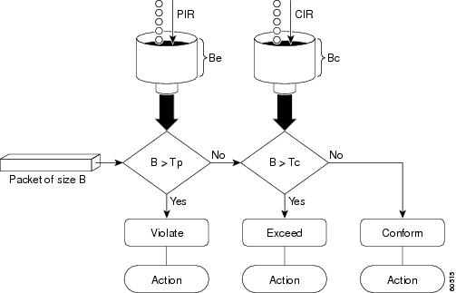
Examples
Setting Priority with an Explicit Policing Rate
In the following example, priority traffic is limited to a committed rate of 1000 kbps regardless of congestion conditions in the network:
In the following example, two-rate traffic policing is configured on a class to limit traffic to an average committed rate of 500 kbps and a peak rate of 1 Mbps:
Traffic marked as conforming to the average committed rate (500 kbps) will be sent as is. Traffic marked as exceeding 500 kbps, but not exceeding 1 Mbps, will be marked with IP Precedence 2 and then sent. All traffic marked as exceeding 1 Mbps will be dropped. The burst parameters are set to 10000 bytes.
Related Commands
policy-map
To enter policy-map configuration mode and create or modify a policy map that can be attached to one or more interfaces to specify a service policy, use the policy-map command in global configuration mode. To delete a policy map, use the no form of this command.
policy-map [ type { control | service }] policy-map-name
no policy-map [ type { control | traffic }] policy-map-name
Syntax Description
Name of the policy map. The name can be a maximum of 40 alphanumeric characters. |
Command Default
Command Modes
Command History
|
|
|
|---|---|
Support for this command was introduced on the Cisco ASR 901 router. |
Usage Guidelines
Use the policy-map command to specify the name of the policy map to be created, added to, or modified before you configure policies for classes whose match criteria are defined in a class map. The policy-map command enters policy-map configuration mode, in which you can configure or modify the class policies for a policy map.
You can configure class policies in a policy map only if the classes have match criteria defined for them. Use the class-map and match commands to configure the match criteria for a class. Because you can configure a maximum of 64 class maps, a policy map cannot contain more than 64 class policies.
A single policy map can be attached to more than one interface concurrently. Except as noted, when you attempt to attach a policy map to an interface, the attempt is denied if the available bandwidth on the interface cannot accommodate the total bandwidth requested by class policies that make up the policy map. In this case, if the policy map is already attached to other interfaces, it is removed from them.
Whenever you modify class policy in an attached policy map, class-based weighted fair queueing (CBWFQ) is notified and the new classes are installed as part of the policy map in the CBWFQ system.
Note![]() Policy-map installation via subscriber-profile is not supported. If you configure an unsupported policy map and there are a large number of sessions, then an equally large number of messages print on the console. For example, if there are 32,000 sessions, then 32,000 messages print on the console at 9,600 baud.
Policy-map installation via subscriber-profile is not supported. If you configure an unsupported policy map and there are a large number of sessions, then an equally large number of messages print on the console. For example, if there are 32,000 sessions, then 32,000 messages print on the console at 9,600 baud.
Examples
The following example creates a policy map called “in-gold-policy”:
protocol (ATM)
To configure a static map for an ATM permanent virtual circuit (PVC), switched virtual circuit (SVC), or virtual circuit (VC) class or to enable Inverse Address Resolution Protocol (ARP) or Inverse ARP broadcasts on an ATM PVC, use the protocol command in the appropriate mode. To remove a static map or disable Inverse ARP, use the no form of this command.
protocol protocol { protocol-address [ virtual-template ] | inarp } [[ no ] broadcast | disable-check-subnet | [ no ] enable-check-subnet ]
no protocol protocol { protocol-address [ virtual-template ] | inarp } [[ no ] broadcast disable-check-subnet | [ no ] enable-check-subnet ]
Syntax Description
Inverse ARP is enabled for IP if the protocol is running on the interface and no static map is configured. Subnet checking for InARP is disabled by default.
Command Modes
Interface-ATM-VC configuration (for an ATM PVC or SVC)
PVC-in-range configuration (for an individual PVC within a PVC range)
PVC range configuration (for an ATM PVC range)
VC-class configuration (for a VC class)
Command History
|
|
|
|---|---|
Support for this command was introduced on the Cisco ASR 901 router. |
Usage Guidelines
Use this command to perform either of the following tasks:
- Configure a static map for an ATM PVC, SVC, or VC class.
- Enable Inverse ARP or Inverse ARP broadcasts on an ATM PVC or PVC range by configuring Inverse ARP directly on the PVC, in the PVC range, or in a VC class (applies to IP protocol only).
- Enable the router to respond to an InARP request when the source IP address contained in the request is not in the subnet as the receiving sub-interface on which PVC is configured.
- Enable the router to accept InARP reply when the peer router's IP address is not in the same subnet as the receiving sub-interface on which the PVC is configured.
- Does not provide support for SVC, PVC, and SVC bundles.
PVC range and PVC-in-range configuration modes support only IP.
Examples
In the following example, the router creates a static map on a VC, indicates that 10.68.34.237 is connected to this VC, and sends ATM pseudobroadcasts:
In the following example, the router removes a static map from a VC and restores the default behavior for Inverse ARP (refer to the “Defaults” section):
In the following example, the VC carries PPP traffic and its associated parameters:
pseudowire-class
To specify the name of a Layer 2 pseudowire-class and enter pseudowire-class configuration mode, use the pseudowire-class command in global configuration mode. To remove a pseudowire class configuration, use the no form of this command.
pseudowire-class pw-class-name
no pseudowire-class pw-class-name
Syntax Description
The name of a Layer 2 pseudowire-class.If you want to configure more than one pseudowire class, define a class name using the pw-class-name parameter. |
Defaults
Command Modes
Command History
|
|
|
|---|---|
Support for this command was introduced on the Cisco ASR 901 router. |
Usage Guidelines
The pseudowire-class command configures a pseudowire-class template that consists of configuration settings used by all attachment circuits bound to the class. A pseudowire-class includes the following configuration settings:
- Data encapsulation type
- Control protocol
- IP address of the local Layer 2 interface
- Type of service (ToS) value in IP headers
The local interface name for each pseudowire class configured between a pair of PE routers can be the same or different.
After entering the pseudowire-class command, the router switches to pseudowire-class configuration mode where PW settings can be configured.
Examples
The following example shows how to enter pseudowire-class configuration mode to configure a PW configuration template named “ether-pw”:
Related Commands
ptp profile telecom
To enable the PTP telecom profile on the router, use ptp profile telecom in the clock configuration mode. To disable PTP telecom profile, use the no form of the command.
Syntax Description
Command Modes
Command History
|
|
|
|---|---|
Support for this command was introduced on the Cisco ASR 901 router. |
Usage Guidelines
Examples
The following example shows how to configure a PTP clock and enter clock configuration mode:
Related Commands
|
|
|
|---|---|
ql-enabled rep segment
Specifies the REP segment used for synchronous Ethernet clock selection.
ql-enabled rep segment segment-id
no ql-enabled rep segment segment-id
Syntax Description
Defaults
Command Modes
Command History
|
|
|
|---|---|
Support for this command was introduced on the Cisco ASR 901 router. |
Usage Guidelines
This command requires that you specify a synchronous Ethernet clock source.
Examples
The following example shows how to use the ql-enabled command:
Related Commands
|
|
|
|---|---|
Enables Resilient Ethernet Protocol (REP) on an interface assigns a segment ID. |
qos-config scheduling-mode min-bw-guarantee
To configure the Quality of Service (QoS) Scheduler, use the qos-config scheduling-mode min-bw-guarantee command in the interface configuration mode in which the queuing policy is configured. To remove this configuration, use the no form of this command. We recommend that you use the qos-config scheduling-mode min-bw-guarantee command for optical ports.
qos-config scheduling-mode min-bw-guarantee
no qos-config scheduling-mode min-bw-guarantee
Syntax Description
Command Default
Command Modes
Interface configuration (config-if) #
Command History
|
|
|
|---|---|
Usage Guidelines
This command allows the per-class rate to use unutilized bandwidth, if any, in addition to the minimum guaranteed bandwidth that is configured.
Examples
The following example shows how to use the qos-config scheduling-mode min-bw-guarantee command:
Related Commands
|
|
|
|---|---|
Selects a particular Gigabit Ethernet interface for configuration. |
rep block port
Use the rep block port interface configuration command on the REP primary edge port to configure Resilient Ethernet Protocol (REP) VLAN load balancing. Use the no form of this command to return to the default configuration.
rep block port { id port-id | neighbor_offset | preferred } vlan { vlan-list | all }
no rep block port { id port-id | neighbor_offset | preferred }
Syntax Description
Defaults
The default behavior after you enter the rep preempt segment privileged EXEC command (for manual preemption) is to block all VLANs at the primary edge port. This behavior remains until you configure the rep block port command.
If the primary edge port cannot determine which port is to be the alternate port, the default action is no preemption and no VLAN load balancing.
Command Modes
Command History
|
|
|
|---|---|
Support for this command was introduced on the Cisco ASR 901 router. |
Usage Guidelines
You must enter this command on the REP primary edge port.
When you select an alternate port by entering an offset number, this number identifies the downstream neighbor port of an edge port. The primary edge port has an offset number of 1; positive numbers above 1 identify downstream neighbors of the primary edge port. Negative numbers identify the secondary edge port (offset number -1) and its downstream neighbors. See Neighbor Offset Numbers in a REP SegmentFigure 1-2.
Figure 1-2 Neighbor Offset Numbers in a REP Segment
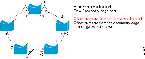
Note![]() You would never enter an offset value of 1 because that is the offset number of the primary edge port itself.
You would never enter an offset value of 1 because that is the offset number of the primary edge port itself.
If you have configured a preempt delay time by entering the rep preempt delay seconds interface configuration command and a link failure and recovery occurs, VLAN load balancing begins after the configured preemption time period elapses without another link failure. The alternate port specified in the load-balancing configuration blocks the configured VLANs and unblocks all other segment ports. If the primary edge port cannot determine the alternate port for VLAN balancing, the default action is no preemption.
Each port in a segment has a unique port ID. The port ID format is similar to the one used by the spanning tree algorithm: a port number (unique on the bridge) associated to a MAC address (unique in the network). To determine the port ID of a port, enter the show interface interface-id rep detail privileged EXEC command.
Examples
This example shows how to configure REP VLAN load balancing on the Switch B primary edge port (Gigabit Ethernet port 0/1) and to configure Gigabit Ethernet port 0/2 of Switch A as the alternate port to block VLANs 1 to 100. The alternate port is identified by its port ID, shown in bold in the output of the show interface rep detail command for the Switch A port.
This example shows how to configure VLAN load balancing by using a neighbor offset number and how to verify the configuration by entering the show interfaces rep detail privileged EXEC command:
Related Commands
rep platform fast-lsl enable
To enable fast Link Status Layer (LSL) configuration on a Cisco ASR 901 Series Aggregate Services Router, use the rep platform fast-lsl enable command in global configuration mode. To disable fast LSL configuration, use the no form of this command.
no rep platform fast-lsl enable
Syntax Description
Command Default
Command Modes
Global configuration (config) #
Command History
|
|
|
|---|---|
This command was introduced on the Cisco ASR 901 Series Aggregation Services Routers. |
Usage Guidelines
This command must be configured on the Cisco ASR 901 Routers to support Resilient Ethernet Protocol (REP) sessions with LSL timers that are less than one second long. When this command is configured, you can expect only subsecond convergence for REP. The subsecond convergence period is also applicable for normal REP sessions, if fast LSL is configured.
Examples
The following example shows how to enable fast LSL configuration on a Cisco ASR 901 Router:
rep platform vlb segment
To configure the VLAN list which forms VLAN load balancing group use the rep platform vlb segment command. For more information on VLAN Load Balancing, see the Cisco ASR 901 Configuration Guide.
rep platform vlb segment segment-id vlan { vlan-list | all}
Syntax Description
Enter vlan vlan-list to block a single VLAN or a range of VLANs, |
|
Enter vlan all to block all VLANs. This is the default configuration. |
Command Modes
Command History
|
|
|
|---|---|
Usage Guidelines
The rep platform vlb segment command should be issued on all Cisco ASR 901 routers participating in VLB for a particular segment and should have a matching VLAN list. This vlan list should also match with the rep block command issued on primary edge port.
Examples
The example shows how to configure the VLAN Load Balancing group:
Related Commands
|
|
|
|---|---|
Configures VLAN load balancing on the primary edge port, identifies the REP alternate port in one of three ways, and configures the VLANs to be blocked on the alternate port. |
rep segment
Use the rep segment interface configuration command to enable Resilient Ethernet Protocol (REP) on the interface and to assign a segment ID to it. Use the no form of this command to disable REP on the interface.
rep segment segment-id [ edge [no-neighbor] [ primary ]] [ preferred ]
Syntax Description
Defaults
REP is disabled on the interface.
When REP is enabled on an interface, the default is for the port to be a regular segment port.
Command Modes
Command History
|
|
|
|---|---|
Support for this command was introduced on the Cisco ASR 901 router. |
Usage Guidelines
REP ports must be Layer 2 trunk ports.
A non-ES REP port can be either an IEEE 802.1Q trunk port or an ISL trunk port.
REP ports should not be configured as one of these port types:
- SPAN destination port
- Private VLAN port
- Tunnel port
- Access port
- REP ports must be network node interfaces (NNIs). REP ports cannot be user-network interfaces (UNIs) or enhanced network interfaces (ENIs).
You must configure two edge ports on each REP segment, a primary edge port and a port to act as a secondary edge port. If you configure two ports in a segment as the primary edge port, for example ports on different switches, the configuration is allowed, but the REP selects one of them to serve as the segment primary edge port.
–![]() There is no limit to the number of REP ports on a switch; however, only two ports on a switch can belong to the same REP segment.
There is no limit to the number of REP ports on a switch; however, only two ports on a switch can belong to the same REP segment.
–![]() If only one port on a switch is configured in a segment, the port should be an edge port.
If only one port on a switch is configured in a segment, the port should be an edge port.
–![]() If two ports on a switch belong to the same segment, they must be both edge ports, both regular segment ports, or one regular port and one edge no-neighbor port. An edge port and regular segment port on a switch cannot belong to the same segment.
If two ports on a switch belong to the same segment, they must be both edge ports, both regular segment ports, or one regular port and one edge no-neighbor port. An edge port and regular segment port on a switch cannot belong to the same segment.
Note![]() Release 12.2(33)MRA does not support the no-neighbor keyword.
Release 12.2(33)MRA does not support the no-neighbor keyword.
–![]() If two ports on a switch belong to the same segment and one is configured as an edge port and one as a regular segment port (a misconfiguration), the edge port is treated as a regular segment port.
If two ports on a switch belong to the same segment and one is configured as an edge port and one as a regular segment port (a misconfiguration), the edge port is treated as a regular segment port.
If you configure two ports in a segment as the primary edge port, for example ports on different switches, the REP selects one of them to serve as the segment primary edge port. Enter the show rep topology privileged EXEC command on a port in the segment to verify which port is the segment primary edge port.
REP interfaces come up in a blocked state and remain in a blocked state until notified that it is safe to unblock. You need to be aware of this to avoid sudden connection losses.
You should configure REP only in networks with redundancy. Configuring REP in a network without redundancy causes loss of connectivity.
Examples
This example shows how to enable REP on a regular (nonedge) segment port:
This example shows how to enable REP on a port and to identify the port as the REP primary edge port:
This example shows how to enable REP on a port and to identify the port as the REP secondary edge port:
You can verify your settings by entering the show interfaces rep privileged EXEC command. To verify which port in the segment is the primary edge port, enter the show rep topology privileged EXEC command.
Related Commands
router isis
To enable the Intermediate System-to-Intermediate System (IS-IS) routing protocol and to specify an IS-IS process, use the router isis command in global configuration mode. To disable IS-IS routing, use the no form of this command.
Syntax Description
Defaults
Command Modes
Command History
|
|
|
|---|---|
Support for this command was introduced on the Cisco ASR 901 router. |
Usage Guidelines
This command is used to enable routing for an area. An appropriate network entity title (NET) must be configured to specify the area address of the area and system ID of the router. Routing must be enabled on one or more interfaces before adjacencies may be established and dynamic routing is possible.
If you have IS-IS running and at least one International Standards Organization Interior Gateway Routing Protocol (ISO-IGRP) process, the IS-IS process and the ISO-IGRP process cannot both be configured without an area tag. The null tag can be used by only one process. If you run ISO-IGRP and IS-IS, a null tag can be used for IS-IS, but not for ISO-IGRP at the same time. However, each area in an IS-IS multiarea configuration should have a nonnull area tag to facilitate identification of the area.
You can configure only one IS-IS routing process to perform Level 2 (interarea) routing. You can configure this process to perform Level 1 (intra-area) routing at the same time. You can configure up to 29 additional processes as Level 1-only processes. If Level 2 routing is configured on any process, all additional processes are automatically configured as Level 1.
An interface cannot be part of more than one area, except in the case where the associated routing process is performing both Level 1 and Level 2 routing. On media such as WAN media where subinterfaces are supported, different subinterfaces could be configured for different areas.
If Level 2 routing is not desired for a given area, use the is-type command to remove Level 2. Level 2 routing can then be enabled on some other router instance.
Explicit redistribution between IS-IS instances is prohibited (prevented by the parser). In other words, you cannot issue a redistribute isis area-tag command in the context of another IS-IS router instance ( router isis area-tag). Redistribution from any other routing protocol into a particular area is possible, and is configured per router instance, as in Cisco IOS software Release 12.0, using the redistribute and route map commands. By default, redistribution is into Level 2.
If multiple Level 1 areas are defined, the Target Address Resolution Protocol (TARP) behaves in the following way:
- The locally assigned target identifier gets the network service access point (NSAP) of the Level 2 area, if present.
- If only Level 1 areas are configured, the router uses the NSAP of the first active Level 1 area as shown in the configuration at the time of TARP configuration (“tarp run”). (Level 1 areas are sorted alphanumerically by tag name, with capital letters coming before lowercase letters. For example, AREA-1 precedes AREA-2, which precedes area-1.) Note that the target identifier NSAP could change following a reload if a new Level 1 area is added to the configuration after TARP is running.
- The router continues to process all Type 1 and 2 protocol data units (PDUs) that are for this router. Type 1 PDUs are processed locally if the specified target identifier is in the local target identifier cache. If not, they are “propagated” (routed) to all interfaces in the same Level 1 area. (The same area is defined as the area configured on the input interface.)
- Type 2 PDUs are processed locally if the specified target identifier is in the local target identifier cache. If not, they are propagated via all interfaces (all Level 1 or Level 2 areas) with TARP enabled. If the source of the PDU is from a different area, the information is also added to the local target identifier cache. Type 2 PDUs are propagated via all static adjacencies.
- Type 4 PDUs (for changes originated locally) are propagated to all Level 1 and Level 2 areas (because internally they are treated as “Level 1-2”).
- Type 3 and 5 PDUs continue to be routed.
- Type 1 PDUs are propagated only via Level 1 static adjacencies if the static NSAP is in one of the Level 1 areas in this router.
After you enter the router isis command, you can enter the maximum number of paths. There can be from 1 to 32 paths.
Examples
The following example starts IS-IS routing with the optional area-tag argument, where CISCO is the value for the area-tag argument:
The following example specifies IS-IS as an IP routing protocol for a process named Finance, and specifies that the Finance process will be routed on Ethernet interface 0 and serial interface 0:
The following example shows usage of the maximum-paths option:
Related Commands
service instance
To configure an Ethernet service instance, use the service instance command in Layer 2 VPN configuration mode. To disable this configuration, use the no form of this command.
service instance id service-type
no service instance id service-type
Syntax Description
Command Default
Command Modes
Layer 2 VPN configuration (config-l2vpn)
Command History
|
|
|
|---|---|
Support for this command was introduced on the Cisco ASR 901 router. |
Usage Guidelines
You must provision a Multiprotocol Label Switching (MPLS) pseudowire before configuring an Ethernet service instance in Layer 2 VPN configuration mode.
Examples
The following example shows how to configure an Ethernet service instance on a Cisco uBR10012 router:
service-policy (policy-map class)
To use a service policy as a QoS policy within a policy map (called a hierarchical service policy), use the service-policy command in policy-map class configuration mode. To disable a particular service policy as a QoS policy within a policy map, use the no form of this command.
service-policy policy-map-name
no service-policy policy-map-name
Syntax Description
Specifies the name of the predefined policy map to be used as a QoS policy. The name can be a maximum of 40 alphanumeric characters. |
Command Default
Command Modes
Policy-map class configuration (config-pmap-c)
Command History
|
|
|
|---|---|
Support for this command was introduced on the Cisco ASR 901 router. |
Usage Guidelines
This command is used to create hierarchical service policies in policy-map class configuration mode.
This command is different from the service-policy [ input | output ] policy-map-name command used in interface configuration mode. The purpose of the service-policy [ input | output ] policy-map-name is to attach service policies to interfaces.
The child policy is the previously defined service policy that is being associated with the new service policy through the use of the service-policy command. The new service policy using the preexisting service policy is the parent policy.
This command has the following restrictions:
- The set command is not supported on the child policy.
- The priority command can be used in either the parent or the child policy, but not both policies simultaneously.
- The shape command can be used in either the parent or the child policy, but not both polices simultaneously on a subinterface.
- The fair-queue command cannot be defined in the parent policy.
- If the bandwidth command is used in the child policy, the bandwidth command must also be used in the parent policy. The one exception is for policies using the default class.
Examples
The following example creates a hierarchical service policy in the service policy called parent:
Related Commands
set cos
To set the Layer 2 class of service (CoS) value of an outgoing packet, use the set cos command in policy-map class configuration mode. To remove a specific CoS value setting, use the no form of this command.
Syntax Description
Command Default
Command Modes
Policy-map class configuration
Command History
|
|
|
|---|---|
Support for this command was introduced on the Cisco ASR 901 router. |
Usage Guidelines
CoS packet marking is supported only in the Cisco Express Forwarding switching path.
The set cos command should be used by a router if a user wants to mark a packet that is being sent to a switch. Switches can leverage Layer 2 header information, including a CoS value marking.
The set cos command can be used only in service policies that are attached in the output direction of an interface. Packets entering an interface cannot be set with a CoS value.
The match cos and set cos commands can be used together to allow routers and switches to interoperate and provide quality of service (QoS) based on the CoS markings.
Layer 2 to Layer 3 mapping can be configured by matching on the CoS value because switches already can match and set CoS values. If a packet that needs to be marked to differentiate user-defined QoS services is leaving a router and entering a switch, the router should set the CoS value of the packet because the switch can process the Layer 2 header.
Using This Command with the Enhanced Packet Marking Feature
You can use this command as part of the Enhanced Packet Marking feature to specify the “from-field” packet-marking category to be used for mapping and setting the CoS value. The “from-field” packet-marking categories are as follows:
If you specify a “from-field” category but do not specify the table keyword and the applicable table-map-nam e argument, the default action will be to copy the value associated with the “from-field” category as the CoS value. For instance, if you configure the set cos precedence command, the precedence value will be copied and used as the CoS value.
You can do the same for the DSCP marking category. That is, you can configure the set cos dscp command, and the DSCP value will be copied and used as the CoS value.
Note![]() If you configure the set cos dscp command, only the first three bits (the class selector bits) of the DSCP field are used.
If you configure the set cos dscp command, only the first three bits (the class selector bits) of the DSCP field are used.
Examples
In the following example, the policy map called “cos-set” is created to assign different CoS values for different types of traffic. This example assumes that the class maps called “voice” and “video-data” have already been created.
policy-map cos-setRouter(config-pmap)#
class voiceRouter(config-pmap-c)#
set cos 1Router(config-pmap-c)#
exitRouter(config-pmap)#
class video-dataRouter(config-pmap-c)#
set cos 2Router(config-pmap-c)#
end
Enhanced Packet Marking Example
In the following example, the policy map called “policy-cos” is created to use the values defined in a table map called “table-map1”. The table map called “table-map1” was created earlier with the table-map (value mapping) command. For more information about the table-map (value mapping) command, see the table-map (value mapping) command page.
In this example, the setting of the CoS value is based on the precedence value defined in “table-map1”:
policy-map policy-cosRouter(config-pmap)#
class class-defaultRouter(config-pmap-c)#
set cos precedence table table-map1
end
Related Commands
set dscp
To mark a packet by setting the differentiated services code point (DSCP) value in the type of service (ToS) byte, use the set dscp command in policy-map class configuration mode. To remove a previously set DSCP value, use the no form of this command.
set [ ip ] dscp { dscp-value }
no set [ ip ] dscp { dscp-value }
Syntax Description
Command Default
Command Modes
Policy-map class configuration
Command History
|
|
|
|---|---|
Support for this command was introduced on the Cisco ASR 901 router. |
Usage Guidelines
Once the DSCP bit is set, other quality of service (QoS) features can then operate on the bit settings.
DSCP and Precedence Values Are Mutually Exclusive
The set dscp command cannot be used with the set precedence command to mark the same packet. The two values, DSCP and precedence, are mutually exclusive. A packet can have one value or the other, but not both.
The network gives priority (or some type of expedited handling) to marked traffic. Typically, you set the precedence value at the edge of the network (or administrative domain); data then is queued according to the precedence. Weighted fair queueing (WFQ) can speed up handling for high-precedence traffic at congestion points. Weighted Random Early Detection (WRED) ensures that high-precedence traffic has lower loss rates than other traffic during times of congestion.
Use of the “from-field” Packet-marking Category
If you are using this command as part of the Enhanced Packet Marking feature, you can use this command to specify the “from-field” packet-marking category to be used for mapping and setting the DSCP value. The “from-field” packet-marking categories are as follows:
If you specify a “from-field” category but do not specify the table keyword and the applicable table-map-nam e argument, the default action will be to copy the value associated with the “from-field” category as the DSCP value. For instance, if you configure the set dscp cos command, the CoS value will be copied and used as the DSCP value.
Note![]() The CoS field is a three-bit field, and the DSCP field is a six-bit field. If you configure the set dscp cos command, only the three bits of the CoS field will be used.
The CoS field is a three-bit field, and the DSCP field is a six-bit field. If you configure the set dscp cos command, only the three bits of the CoS field will be used.
If you configure the set dscp qos-group command, the QoS group value will be copied and used as the DSCP value.
The valid value range for the DSCP is a number from 0 to 63. The valid value range for the QoS group is a number from 0 to 99. Therefore, when configuring the set dscp qos-group command, note the following points:
- If a QoS group value falls within both value ranges (for example, 44), the packet-marking value will be copied and the packets will be marked.
- If QoS group value exceeds the DSCP range (for example, 77), the packet-marking value will not be copied and the packet will not be marked. No action is taken.
Set DSCP Values in IPv6 Environments
When this command is used in IPv6 environments, the default match occurs on both IP and IPv6 packets. However, the actual packets set by this function are only those which meet the match criteria of the class-map containing this function.
Set DSCP Values for IPv6 Packets Only
To set DSCP values for IPv6 values only, the match protocol ipv6 command must also be used. Without that command, the precedence match defaults to match both IPv4 and IPv6 packets.
Set DSCP Values for IPv4 Packets Only
To set DSCP values for IPv4 packets only, use the ip keyword. Without the ip keyword, the match occurs on both IPv4 and IPv6 packets.
Examples
Packet-marking Values and Table Map
In the following example, the policy map called “policy1” is created to use the packet-marking values defined in a table map called “table-map1”. The table map was created earlier with the table-map (value mapping) command. For more information about the table-map (value mapping) command, see the table-map (value mapping) command page.
In this example, the DSCP value will be set according to the CoS value defined in the table map called “table-map1”.
policy-map policy1Router(config-pmap)#
class class-defaultRouter(config-pmap-c)#
set dscp cos table table-map1
end
The set dscp command is applied when you create a service policy in QoS policy-map configuration mode. This service policy is not yet attached to an interface. For information on attaching a service policy to an interface, refer to the “Modular Quality of Service Command-Line Interface” section of the Cisco IOS Quality of Service Solutions Configuration Guide.
Related Commands
set ip dscp
The set ip dscp command is replaced by the set dscp command. See the set dscp command for more information.
set ip precedence (policy-map)
The set ip precedence (policy-map) command is replaced by the set precedence command. See the set precedence command for more information.
set ip precedence (route-map)
To set the precedence value (and an optional IP number or IP name) in the IP header, use the set ip precedence command in route-map configuration mode. To leave the precedence value unchanged, use the no form of this command.
set ip precedenc e [ number | name ]
Syntax Description
(Optional) A number or name that sets the precedence bits in the IP header. The values for the number argument and the corresponding name argument are listed in Table 1-4 from least to most important. |
Command Default
Command Modes
Command History
|
|
|
|---|---|
Support for this command was introduced on the Cisco ASR 901 router. |
Usage Guidelines
Table 1-4 lists the values for the number argument and the corresponding name argument for precedence values in the IP header. They are listed from least to most important.
|
|
|
You can set the precedence using either a number or the corresponding name. Once the IP Precedence bits are set, other QoS services such as weighted fair queueing (WFQ) and Weighted Random Early Detection (WRED) then operate on the bit settings.
The network gives priority (or some type of expedited handling) to marked traffic through the application of WFQ or WRED at points downstream in the network. Typically, you set IP Precedence at the edge of the network (or administrative domain); data then is queued based on the precedence. WFQ can speed up handling for certain precedence traffic at congestion points. WRED can ensure that certain precedence traffic has lower loss rates than other traffic during times of congestion.
The mapping from arguments such as routine and priority to a precedence value is useful only in some instances. That is, the use of the precedence bit is evolving. You can define the meaning of a precedence value by enabling other features that use the value. In the case of the high-end Internet QoS available from Cisco, IP Precedences can be used to establish classes of service that do not necessarily correspond numerically to better or worse handling in the network.
Use the route-map (IP) global configuration command with the match and set route-map configuration commands to define the conditions for redistributing routes from one routing protocol into another, or for policy routing. Each route-map command has an associated list of match and set commands. The match commands specify the match criteria—the conditions under which redistribution or policy routing is allowed for the current route-map command. The set commands specify the set actions—the particular redistribution or policy routing actions to perform if the criteria enforced by the match commands are met. The no route-map command deletes the route map.
The set route-map configuration commands specify the redistribution set actions to be performed when all of the match criteria of a route map are met.
Examples
The following example sets the IP Precedence to 5 (critical) for packets that pass the route map match:
Related Commands
|
|
|
|---|---|
Changes the minimum and maximum packet thresholds for the DSCP value. |
set ip precedence tunnel
To set the precedence value in the header of a Layer 2 Tunnel Protocol Version 3 (L2TPv3) or Generic Routing Encapsulation (GRE) tunneled packet for tunnel marking, use the set ip precedence tunnel command in policy-map class configuration mode. To disable this functionality, use the no form of this command.
set ip precedence tunnel precedence -value
no set ip precedence tunnel precedence-value
Syntax Description
Number from 0 to 7 that identifies the precedence value of the tunnel header. |
Command Default
Command Modes
Policy-map class configuration (config-pmap-c)
Command History
|
|
|
|---|---|
Support for this command was introduced on the Cisco ASR 901 router. |
Usage Guidelines
It is possible to configure L2TPv3 (or GRE) tunnel marking and the ip tos command at the same time. However, Modular Quality of Service (QoS) Command-Line Interface (CLI) (MQC) (L2TPv3 or GRE) tunnel marking has higher priority over ip tos commands, meaning that tunnel marking always rewrites the IP header of the tunnel packet and overwrites the values set by ip tos commands. The order of enforcement is as follows when these commands are used simultaneously:
1. set ip dscp tunnel or set ip precedence tunnel (L2TPv3 or GRE tunnel marking)
This is the designed behavior. We recommend that you configure only L2TPv3 (or GRE) tunnel marking and reconfigure any peers configured with the ip tos command to use L2TPv3 (or GRE) tunnel marking.
Note![]() For Cisco IOS Release 12.4(15)T2, marking GRE-tunneled packets is supported only on platforms equipped with a Cisco RPM-XF.
For Cisco IOS Release 12.4(15)T2, marking GRE-tunneled packets is supported only on platforms equipped with a Cisco RPM-XF.
Examples
The following example shows the set ip precedence tunnel command used in a tunnel marking configuration. In this example, a class map called “MATCH_FRDE” has been configured to match traffic on the basis of the Frame Relay discard eligible (DE) bit setting. Also, a policy map called “policy1” has been created within which the set ip precedence tunnel command has been configured.
Router(config)# policy-map policy1
Router(config-pmap)# class tunnel
Related Commands
|
|
|
|---|---|
Specifies the ToS level for IP traffic in the TN3270 server. |
|
Sets the DSCP value in the header of an L2TPv3 tunneled packet. |
set ip tos (route-map)
To set the type of service (ToS) bits in the header of an IP packet, use the set ip tos command in route-map configuration mode. To leave the ToS bits unchanged, use the no form of this command.
set ip tos [ tos - bit - value | max-reliability | max-throughput | min-delay | min-monetary-cost | normal ]
Syntax Description
(Optional) A value (number) from 0 to 15 that sets the ToS bits in the IP header. See Table 1-5 for more information. |
|
Command Default
Command Modes
Command History
|
|
|
|---|---|
Support for this command was introduced on the Cisco ASR 901 router. |
Usage Guidelines
This command allows you to set four bits in the ToS byte header. Table 1-5 shows the format of the four bits in binary form.
|
|
|
|
|
|
The T3 bit sets the delay. Setting T3 to 0 equals normal delay, and setting it to 1 equals low delay.
The T2 bit sets the throughput. Setting this bit to 0 equals normal throughput, and setting it to 1 equals maximum throughput. Similarly, the T1 and T0 bits set reliability and cost, respectively. Therefore, as an example, if you want to set a packet with the following requirements:
You would set the ToS to 9, which is 1001 in binary format.
Use the route-map (IP) global configuration command with the match and set (route-map) configuration commands to define the conditions for redistributing routes from one routing protocol into another, or for policy routing. Each route-map command has an associated list of match and set commands. The match commands specify the match criteria—the conditions under which redistribution or policy routing is allowed for the current route-map command. The set commands specify the set actions—the particular redistribution or policy routing actions to perform if the criteria enforced by the match commands are met. The no route-map command deletes the route map.
The set (route-map) commands specify the redistribution set actions to be performed when all of the match criteria of a route map are met.
Examples
The following example sets the IP ToS bits to 8 (minimum delay as shown in Table 1-5 ) for packets that pass the route-map match:
Related Commands
set network-clocks
This command causes the router to reselect a network clock; the router selects a new clock based on clock priority.
set network-clocks [force-reselect | next-select]
Syntax Description
Forces the router to select the next available network clock. |
Command Modes
Command History
|
|
|
|---|---|
Support for this command was introduced on the Cisco ASR 901 router. |
Examples
The following example shows how to use the set network-clocks force-reselect command:
Related Commands
|
|
|
|---|---|
Displays information about all clocks configured on the router. |
set precedence
To set the precedence value in the packet header, use the set precedence command in policy-map class configuration mode. To remove the precedence value, use the no form of this command.
set precedence { precedence-value }
no set precedence { precedence-value }
Syntax Description
A number from 0 to 7 that sets the precedence bit in the packet header. |
Command Default
Command Modes
Policy-map class configuration
Command History
|
|
|
|---|---|
Support for this command was introduced on the Cisco ASR 901 router. |
Usage Guidelines
If a router is loaded with an image from this version (that is, Cisco IOS Release 12.2(13)T) that contained an old configuration, the set ip precedence command is still recognized. However, the set precedence command will be used in place of the set ip precedence command.
The set precedence command cannot be used with the set dscp command to mark the same packet. The two values, DSCP and precedence, are mutually exclusive. A packet can be one value or the other, but not both.
Once the precedence bits are set, other quality of service (QoS) features such as weighted fair queueing (WFQ) and Weighted Random Early Detection (WRED) then operate on the bit settings.
The network gives priority (or some type of expedited handling) to marked traffic through the application of WFQ or WRED at points downstream in the network. Typically, you set the precedence value at the edge of the network (or administrative domain); data then is queued according to the specified precedence. WFQ can speed up handling for certain precedence traffic at congestion points. WRED can ensure that certain precedence traffic has lower loss rates than other traffic during times of congestion.
The set precedence command cannot be used with the set dscp command to mark the same packet. The two values, differentiated services code point (DSCP) and precedence, are mutually exclusive. A packet can have one value or the other, but not both.
Using This Command with the Enhanced Packet Marking Feature
If you are using this command as part of the Enhanced Packet Marking feature, you can use this command to specify the “from-field” packet-marking category to be used for mapping and setting the precedence value. The “from-field” packet-marking categories are as follows:
If you specify a “from-field” category but do not specify the table keyword and the applicable table-map-nam e argument, the default action will be to copy the value associated with the “from-field” category as the precedence value. For instance, if you configure the set precedence cos command, the CoS value will be copied and used as the precedence value.
You can do the same for the QoS group-marking category. That is, you can configure the set precedence qos-group command, and the QoS group value will be copied and used as the precedence value.
The valid value range for the precedence value is a number from 0 to 7. The valid value range for the QoS group is a number from 0 to 99. Therefore, when configuring the set precedence qos-group command, note the following points:
- If a QoS group value falls within both value ranges (for example, 6), the packet-marking value will be copied and the packets will be marked.
- If QoS group value exceeds the precedence range (for example, 10), the packet-marking value will not be copied, and the packet will not be marked. No action is taken.
Setting Precedence Values for IPv4 Packets Only
To set the precedence values for IPv4 packets only, use a command involving the ip keyword like the match ip precedence or match ip dscp command or include the match protocol ip command along with the others in the class map. Without the additional ip keyword, the class-map may match both IPv6 and IPv4 packets (depending on the other match criteria) and the set precedence or set dscp command may act upon both types of packets.
Examples
The following example shows how to use the set precedence command.
policy-map policy-cosRouter(config-pmap)#
class class-defaultRouter(config-pmap-c)#
set precedence 4
end
The set precedence command is applied when you create a service policy in QoS policy-map configuration mode. This service policy is not yet attached to an interface or to an ATM virtual circuit. For information on attaching a service policy to an interface, refer to the “Modular Quality of Service Command-Line Interface Overview” chapter of the Cisco IOS Quality of Service Solutions Configuration Guide.
Related Commands
shape (percent)
To specify average or peak rate traffic shaping on the basis of a percentage of bandwidth available on an interface, use the shape command in policy-map class configuration mode. To remove traffic shaping, use the no form of this command.
shape { average } percent percentage [ sustained-burst-in-msec ms ] [ be excess-burst-in-msec ms ] [ bc committed-burst-in-msec ms ]
no shape { average } percent percentage [ sustained-burst-in-msec ms ] [ be excess-burst-in-msec ms ] [ bc committed-burst-in-msec ms ]
Syntax Description
Command Default
Command Modes
Policy-map class configuration (config-pmap-c)
Command History
|
|
|
|---|---|
Support for this command was introduced on the Cisco ASR 901 router. |
Usage Guidelines
This command calculates the committed information rate (CIR) on the basis of a percentage of the available bandwidth on the interface. Once a policy map is attached to the interface, the equivalent CIR value in bits per second (bps) is calculated on the basis of the interface bandwidth and the percent value entered with this command. The show policy-map interface command can then be used to verify the CIR bps value calculated.
The calculated CIR bps rate must be in the range of 8000 and 154,400,000 bps. If the rate is less than 8000 bps, the associated policy map cannot be attached to the interface. If the interface bandwidth changes (for example, more is added), the CIR bps values are recalculated on the basis of the revised amount of bandwidth. If the CIR percentage is changed after the policy map is attached to the interface, the bps value of the CIR is recalculated.
Conform Burst and Peak Burst Sizes in Milliseconds
This command also allows you to specify the values for the conform burst size and the peak burst size in milliseconds. If you want bandwidth to be calculated as a percentage, the conform burst size and the peak burst size must be specified in milliseconds (ms).
The traffic shape converge rate depends on the traffic pattern and the time slice (Tc) parameter, which is directly affected by the bc that you configured. The Tc and the average rate configured are used to calculate bits per interval sustained. Therefore, to ensure that the shape rate is enforced, use a bc that results in a Tc greater than 10 ms.
The shape (percent) command is often used in conjunction with the bandwidth and priority commands. The bandwidth and priority commands can be used to calculate the total amount of bandwidth available on an entity (for example, a physical interface). When the bandwidth and priority commands calculate the total amount of bandwidth available on an entity, the following guidelines are invoked:
- If the entity is a physical interface, the total bandwidth is the bandwidth on the physical interface.
- If the entity is a shaped ATM permanent virtual circuit (PVC), the total bandwidth is calculated as follows:
–![]() For a variable bit rate (VBR) virtual circuit (VC), the sustained cell rate (SCR) is used in the calculation.
For a variable bit rate (VBR) virtual circuit (VC), the sustained cell rate (SCR) is used in the calculation.
–![]() For an available bit rate (ABR) VC, the minimum cell rate (MCR) is used in the calculation.
For an available bit rate (ABR) VC, the minimum cell rate (MCR) is used in the calculation.
For more information on bandwidth allocation, see the “Congestion Management Overview” chapter in the Cisco IOS Quality of Service Solutions Configuration Guide.
Examples
The following example configures traffic shaping using an average shaping rate on the basis of a percentage of bandwidth. In this example, 25 percent of the bandwidth has been specified. Additionally, an optional be value and bc value (100 ms and 400 ms, respectively) have been specified.
Router(config-pmap-c)# shape average percent 25 20 ms be 100 ms bc 400 ms
After the policy map and class maps are configured, the policy map is attached to interface as shown in the following example.
interface gigabitethernet0/1
service-policy input policy1
Related Commands
shape (policy-map class)
To shape traffic to the indicated bit rate according to the algorithm specified, or to enable ATM overhead accounting, use the shape command in policy-map class configuration mode. To remove shaping and leave the traffic unshaped, use the no form of this command.
shape [ average | peak ] mean-rate [ burst-size ] [ excess-burst-size ]
Syntax Description
Command Default
When the excess burst size (Be) is not configured, the default Be value is equal to the committed burst size (Bc). For more information about burst size defaults, see the Usage Guidelines section.
Command Modes
Policy-map class configuration (config-pmap-c)
Command History
|
|
|
|---|---|
Support for this command was introduced on the Cisco ASR 901 router. |
Usage Guidelines
The measurement interval is the committed burst size (Bc) divided by committed information rate (CIR). Bc cannot be set to 0. If the measurement interval is too large (greater than 128 milliseconds), the system subdivides it into smaller intervals.
If you do not specify the committed burst size (Bc) and the excess burst size (Be), the algorithm decides the default values for the shape entity. The algorithm uses a 4 milliseconds measurement interval, so Bc is CIR * (4 / 1000).
Burst sizes larger than the default committed burst size (Bc) need to be explicitly specified. The larger the Bc, the longer the measurement interval. A long measurement interval may affect voice traffic latency, if applicable.
When the excess burst size (Be) is not configured, the default value is equal to the committed burst size (Bc).
Examples
The following example configures a shape entity with a CIR of 1 Mbps and attaches the policy map called dts-interface-all-action to interface pos1/0/0:
Traffic Shaping Overhead Accounting for ATM
When a parent policy has ATM overhead accounting enabled for shaping, you are not required to enable accounting at the child level using the police command. In the following configuration example, ATM overhead accounting is enabled for bandwidth on the gaming and class-default class of the child policy map named subscriber_classes and on the class-default class of the parent policy map named subscriber_line. The voip and video classes do not have ATM overhead accounting explicitly enabled. These priority classes have ATM overhead accounting implicitly enabled because the parent policy has ATM overhead accounting enabled. Notice that the features in the parent and child policies use the same encapsulation type.
class class-default
Related Commands
show asr901 multicast-support
To display the platform support for IPv4 or IPv6 multicast, use the show asr901 multicast-support command.
Syntax Description
Command Modes
Command History
|
|
|
|---|---|
This command was introduced on the Cisco ASR 901 Series Aggregation Services Routers. |
Usage Guidelines
This command displays the platform support for IPv4 or IPv6 multicast.
Examples
This example shows the output from show asr901 multicast-support command on a Cisco ASR 901 series router:
Related Commands
|
|
|
|---|---|
show atm cell-packing
To display cell packing information for the Layer 2 attachment circuits (ACs) configured on your system, use the show atm cell-packing command in privileged EXEC mode.
Syntax Description
Command Modes
Command History
|
|
|
|---|---|
Support for this command was introduced on the Cisco ASR 901 router. |
Examples
The following example shows output from the show atm cell-packing command:
Related Commands
|
|
|
|---|---|
show cem circuit
To display a summary of CEM circuits, use the show cem circuit command in privileged EXEC mode.
Syntax Description
(Optional) Identifies the circuit configured with the cem-group command. |
Command Modes
Command History
|
|
|
|---|---|
Support for this command was introduced on the Cisco ASR 901 router. |
Examples
The following examples show the output generated by this command;
Related Commands
|
|
|
|---|---|
Displays platform-specific error counters for all CEM circuits. |
|
Displays platform-specific error counters for all CEM circuits. |
show cem platform
To display platform-specific error counters for all CEM circuits, use the show cem platform command in privileged EXEC mode.
Syntax Description
(Optional) Identifies the CEM interface (for example, CEM0/1). |
Command Modes
Command History
|
|
|
|---|---|
Support for this command was introduced on the Cisco ASR 901 router. |
Examples
The following examples show the output generated by this command:
Related Commands
|
|
|
|---|---|
Displays platform-specific error counters for all CEM circuits. |
show etherchannel
To display EtherChannel information for a channel, use the show etherchannel command in privileged EXEC mode.
show etherchannel [ channel-group ] {port-channel | detail | summary | port | load-balance}
Syntax Description
(Optional) Number of the channel group. If you do not specify a value for the channel-group argument, all channel groups are displayed. |
|
Command Modes
Command History
|
|
|
|---|---|
Support for this command was introduced on the Cisco ASR 901 router. |
Usage Guidelines
If you do not specify a value for the channel-group argument, all channel groups are displayed.
If the interface is configured as part of the channel in ON mode, the show etherchannel protocol command displays Protocol: - (Mode ON).
- In the output of the show etherchannel summary command, the following conventions apply:
- In the column that displays the protocol that is used for the channel, if the channel mode is ON, a hyphen (-) is displayed.
For LACP, multiple aggregators are supported. For example, if two different bundles are created, Po1 indicates the primary aggregator, and Po1A and Po1B indicates the secondary aggregators.
In the output of the show etherchannel load-balance command, the following conventions apply:
- For EtherChannel load balancing of IPv6 traffic, if the traffic is bridged onto an EtherChannel (for example, it is a Layer 2 channel and traffic in the same VLAN is bridged across it), the traffic is always load balanced by the IPv6 addresses or src, dest, or src-dest, depending on the configuration. For this reason, the switch ignores the MAC/IP/ports for bridged IPv6 traffic. If you configure src-dst-mac, the src-dst-ip(v6) address is displayed. If you configure src-mac, the src-ip(v6) address is displayed.
- IPv6 traffic that is routed over a Layer 2 or a Layer 3 channel is load balanced based on MAC addresses or IPv6 addresses, depending on the configuration. The MAC/IP and the src/dst/src-dst are supported, but load balancing that is based on Layer 4 ports is not supported. If you use the port keyword, the IPv6 addresses or either src, dst, or src-dst, is displayed.
Examples
The following example shows how to verify the configuration:
Related Commands
|
|
|
|---|---|
Assigns and configures an EtherChannel interface to an EtherChannel group. |
|
Sets the protocol that is used on an interface to manage channeling. |
show ethernet loopback
To display information about the per port Ethernet loopbacks configured on a router or an interface, use the show ethernet loopback command in privileged EXEC mode.
show ethernet loopback active [brief | [ interface-id ] [service-instance id]]
Syntax Description
(Optional) Displays loopback information for the specified interface. Only physical interfaces support ethernet loopback. |
|
Command Modes
Command History
|
|
|
|---|---|
Usage Guidelines
If you do not specify an interface-id, all configured loopbacks appear. The router supports a maximum of two Ethernet loopback configurations.
Examples
The following example shows how to verify the configuration:
Related Commands
|
|
|
|---|---|
show interface port-channel
To display the EtherChannel interfaces and channel identifiers, with their mode and operational status, use the show interface port-channel command in privileged EXEC mode.
show interface port-channel { number }
Syntax Description
Optional value enables the display of information for one port channel interface number. The range is from 1 to 8. |
Command Default
Command Modes
Command History
|
|
|
|---|---|
Support for this command was introduced on the Cisco ASR 901 router. |
show interfaces rep
Use the show interfaces rep User EXEC command to display Resilient Ethernet Protocol (REP) configuration and status for a specified interface or for all interfaces.
show interfaces [ interface-id ] rep [ detail ] [ | { begin | exclude | include } expression ]
Syntax Description
Command Modes
Command History
|
|
|
|---|---|
Support for this command was introduced on the Cisco ASR 901 router. |
Usage Guidelines
In the output for the show interface rep [ detail ] command, in addition to an Open, Fail, or AP (alternate port) state, the Port Role might show as Fail Logical Open ( FailLogOpen) or Fail No Ext Neighbor ( FailNoNbr). These states indicate that the port is physically up, but REP is not configured on the neighboring port. In this case, one port goes into a forwarding state for the data path to help maintain connectivity during configuration. The Port Role for this port shows as Fail Logical Open; the port forwards all data traffic on all VLANs. The other failed Port Role shows as Fail No Ext Neighbor; this port blocks traffic for all VLANs.
When the external neighbors for the failed ports are configured, the failed ports go through the alternate port state transitions and eventually go to an Open state or remain as the alternate port, based on the alternate port election mechanism.
The output of this command is also included in the show tech-support privileged EXEC command output.
Expressions are case sensitive. For example, if you enter | exclude output, the lines that contain output are not displayed, but the lines that contain Output are displayed.
Examples
This is sample output from the show interface rep command:
This is sample output from the show interface rep command when the edge port is configured to have no REP neighbor. Note the asterisk (*) next to Primary Edge.
This is sample output from the show interface rep command when external neighbors are not configured:
This is sample output from the show interface rep detail command for a specified interface:
Related Commands
show ip vrf
To display the set of defined Virtual Private Network (VPN) routing and forwarding (VRF) instances and associated interfaces, use the show ip vrf command in privileged EXEC mode.
show ip vrf [ brief | detail | interfaces | id ] [ vrf-name ] [ output-modifiers ]
Syntax Description
Defaults
When no keywords or arguments are specified, the command shows concise information about all configured VRFs.
Command Modes
Command History
|
|
|
|---|---|
Support for this command was introduced on the Cisco ASR 901 router. |
Usage Guidelines
Use this command to display information about VRFs. Two levels of detail are available:
- The brief keyword (or no keyword) displays concise information.
- The detail keyword displays all information.
To display information about all interfaces bound to a particular VRF, or to any VRF, use the interfaces keyword. To display information about VPN IDs assigned to a PE router, use the id keyword.
Examples
The following example displays information about all the VRFs configured on the router, including the downstream VRF for each associated VAI. The lines that are highlighted (for documentation purposes only) indicate the downstream VRF.
Table 1-6 describes the significant fields shown in the display.
|
|
|
The following example displays detailed information about all of the VRFs configured on the router, including all of the VAIs associated with each VRF:
Table 1-7 describes the significant fields shown in the display.
|
|
|
The following example shows the interfaces bound to a particular VRF:
Table 1-8 describes the significant fields shown in the display.
|
|
|
Displays the state of the protocol (up or down) for each VRF interface. |
The following is sample output that shows all the VPN IDs that are configured in the router and their associated VRF names and VRF route distinguishers (RDs):
Table 1-9 describes the significant fields shown in the display.
|
|
|
show mac-address-table
To display the MAC address table, use the show mac-address-table command in privileged EXEC mode.
show mac-address-table [address mac-addr ] [aging-time vlan-id ] [count vlan-id ] [dynamic [address mac-address | interface type slot/port | vlan vlan-id ]] [interface type/number ] [multicast [{igmp-snooping | mld-snooping | vlan vlan-id }]] [static [[{address mac-addr } | {interface interface/switch-num//slot/port } | vlan vlan-id ] [vlan vlan-id ]
Syntax Description
Command Default
Command Modes
Command History
|
|
|
|---|---|
Support for this command was introduced on the Cisco ASR 901 router. |
Usage Guidelines
The mac-addr is a 48-bit MAC address and the valid format is H.H.H.
The count keyword displays the number of multicast entries.
The multicast keyword displays the multicast MAC addresses (groups) in a VLAN or displays all statically installed or IGMP snooping-learned entries in the Layer 2 table.
The dynamic entries that are displayed in the Learn field are always set to Yes.
Examples
The following example shows the output for the show mac address-table count command:
show network-clock synchronization
Displays the information about network-clock synchronization.
Command Modes
Command History
|
|
|
|---|---|
Support for this command was introduced on the Cisco ASR 901 router. |
Usage Guidelines
This command confirms if the system is in revertive mode or non-revertive mode and verify the non-revertive configurations.
Examples
This command shows the output of the show network-clock synchronization command to confirm if the system is in revertive mode:
Use the show network-clock synchronization detail command to display all details of network-clock synchronization parameters at the global and interface levels.
show platform hardware
To display the status of hardware devices on the Cisco ASR 901, use the show platform hardware command. The command displays information about hardware devices on the Cisco ASR 901 for troubleshooting and debugging purposes.
show platform hardware {adrian | bits | cpld | cpu | ethernet | fio | hwic | rtm | stratum | ufe winpath
Syntax Description
Command Modes
Command History
|
|
|
|---|---|
Support for this command was introduced on the Cisco ASR 901 router. |
Related Commands
|
|
|
|---|---|
show platform ptp state
To display the status of ptp protocol on the Cisco ASR 901 router, use the show platform ptp state command.
Syntax Description
Command Modes
Command History
|
|
|
|---|---|
Support for this command was introduced on the Cisco ASR 901 router. |
Examples
The following example shows sample output for show platform ptp state comamnd:
Related Commands
|
|
|
|---|---|
Displays statistics about the ptp protocol on the Cisco ASR 901 router. |
show platform ptp stats
To display statistics about ptp protocol on the Cisco ASR 901 router, use the show platform ptp stats command.
Syntax Description
Command Modes
Command History
|
|
|
|---|---|
Support for this command was introduced on the Cisco ASR 901 router. |
Examples
The following example shows sample output for show platform ptp stats comamnd:
Related Commands
|
|
|
|---|---|
Displays the status of the ptp protocol on the Cisco ASR 901 router. |
show platform ptp stats detailed
To display detailed statistics about ptp protocol on the Cisco ASR 901 router, use the show platform ptp stats detailed command.
show platform ptp stats detailed
Syntax Description
Command Modes
Command History
|
|
|
|---|---|
Support for this command was introduced on the Cisco ASR 901 router. |
Examples
The following example shows sample output for show platform ptp stats detailed comamnd:
Related Commands
|
|
|
|---|---|
Displays the statistics of the ptp protocol on the Cisco ASR 901 router. |
show platform tcam detailed
To display the current occupancy that includes per-TCAM rules information such as number of TCAM rules used or free and feature(s) using the TCAM rule, use the show platform tcam detailed command.
Syntax Description
Command Modes
Command History
|
|
|
|---|---|
This command was introduced on the Cisco ASR 901 Series Aggregation Services Routers. |
Examples
The following is sample output from the show platform tcam detailed command:
show platform tcam summary
To display the current occupancy of TCAM with summary of the number of TCAM rules allocated or free, use the show platform tcam summary command.
Syntax Description
Command Modes
Command History
|
|
|
|---|---|
This command was introduced on the Cisco ASR 901 Series Aggregation Services Routers. |
Examples
The following is sample output freom the show platform tcam summary command:
show policy-map
To display the configuration of all classes for a specified service policy map or of all classes for all existing policy maps, use the show policy-map command in user EXEC or privileged EXEC mode.
show policy-map [ policy-map ]
Syntax Description
(Optional) Name of the service policy map whose complete configuration is to be displayed. The name can be a maximum of 40 characters. |
Command Default
Command Modes
User EXEC (>)
Privileged EXEC (#)
Command History
|
|
|
|---|---|
Support for this command was introduced on the Cisco ASR 901 router. |
Usage Guidelines
The show policy-map command displays the configuration of a policy map created using the policy-map command. You can use the show policy-map command to display all class configurations comprising any existing service policy map, whether or not that policy map has been attached to an interface. The command displays:
Examples
This section provides sample output from typical show policy-map commands. Depending upon the interface or platform in use and the options enabled (for example, Weighted Fair Queueing [WFQ]), the output you see may vary slightly.
The following is sample output from the show policy-map command. This sample output displays the contents of a policy map called “policy1.” In policy 1, traffic policing on the basis of a committed information rate (CIR) of 20 percent has been configured, and the bc and be have been specified in milliseconds. As part of the traffic policing configuration, optional conform, exceed, and violate actions have been specified.
Table 1-10 describes the significant fields shown in the display.
Related Commands
show policy-map interface
To display the statistics and the configurations of the input and output policies that are attached to an interface, use the show policy-map interface command in user EXEC or privileged EXEC mode.
show policy-map interface [ type access-control ] type number [ vc [ vpi / ] vci ] [ dlci dlci ] [ input | output ]
Syntax Description
Command Default
This command displays the packet statistics of all classes that are configured for all service policies on the specified interface or subinterface or on a specific permanent virtual circuit (PVC) on the interface.
The absence of both the forward slash (/) and a vpi value defaults the vpi value to 0. If this value is omitted, information for all virtual circuits (VCs) on the specified ATM interface or subinterface is displayed.
Command Modes
Command History
|
|
|
|---|---|
Support for this command was introduced on the Cisco ASR 901 router. |
Usage Guidelines
The show policy-map interface command displays the packet statistics for classes on the specified interface or the specified PVC only if a service policy has been attached to the interface or the PVC.
The counters displayed after the show policy-map interface command is entered are updated only if congestion is present on the interface.
Related Commands
show ptp port running detail
To display the running details of the PTP port, use the show ptp port running detail command.
Syntax Description
Command Modes
Command History
|
|
|
|---|---|
This command was introduced on the Cisco ASR 901 Series Aggregation Services Routers. |
Usage Guidelines
This command is used to display running details of the PTP port.
Note![]() Accuracy and log variance are not displayed for the telecom profile since the fields are not required for selecting the best master.
Accuracy and log variance are not displayed for the telecom profile since the fields are not required for selecting the best master.
Examples
This example shows the output from show ptp port running detail command on a Cisco ASR 901 router:
show rep topology
Use the show rep topology User EXEC command to display Resilient Ethernet Protocol (REP) topology information for a segment or for all segments, including the primary and secondary edge ports in the segment.
show rep topology [ segment segment_id ] [ archive ] [ detail ] [ | { begin | exclude | include } expression ]
Syntax Description
Command Modes
Command History
|
|
|
|---|---|
Support for this command was introduced on the Cisco ASR 901 router. |
Usage Guidelines
The output of this command is also included in the show tech-support privileged EXEC command output.
Expressions are case sensitive. For example, if you enter | exclude output, the lines that contain output are not displayed, but the lines that contain Output are displayed.
Examples
This is a sample output from the show rep topology segment privileged EXEC command:
This is a sample output from the show rep topology command when the edge ports are configured to have no REP neighbor:
This example shows output from the show rep topology detail command:
<output truncated>
This example shows output from the show rep topology segment archive command:
Related Commands
|
|
|
|---|---|
Enables REP on an interface and assigns a segment ID. This command is also used to configure a port as an edge port, a primary edge port, or a preferred port. |
show table-map
To display the configuration of a specified table map or all table maps, use the show table-map command in EXEC mode.
Syntax Description
Name of table map used to map one packet-marking value to another. The name can be a maximum of 64 alphanumeric characters. |
Command Modes
Command History
|
|
|
|---|---|
Support for this command was introduced on the Cisco ASR 901 router. |
Examples
The sample output of the show table-map command shows the contents of a table map called “map 1”. In “map1”, a “to–from” relationship has been established and a default value has been defined. The fields for establishing the “to–from” mappings are further defined by the policy map in which the table map will be configured. (Configuring a policy map is the next logical step after creating a table map.)
For instance, a precedence or differentiated services code point (DSCP) value of 0 could be mapped to a class of service (CoS) value of 1, or vice versa, depending on the how the values are defined in the table map. Any values not explicitly defined in a “to–from” relationship will be set to a default value.
The following sample output of the show table-map command displays the contents of a table map called “map1”. In this table map, a packet-marking value of 0 is mapped to a packet-marking value of 1. All other packet-marking values are mapped to the default value 3.
Table 1-11 describes the fields shown in the display.
Related Commands
show xconnect
To display information about xconnect attachment circuits and pseudowires (PWs), use the show xconnect all command in privileged EXEC mode.
show xconnect { all | interface interface | peer ip-address { all | vcid vcid }} [ detail ]
Syntax Description
Command Modes
Command History
|
|
|
|---|---|
Support for this command was introduced on the Cisco ASR 901 router. |
Usage Guidelines
The show xconnect all command can be used to display, sort, and filter basic information about all xconnect attachment circuits and PWs.
You can use the show xconnect all command output to help determine the appropriate steps to troubleshoot an xconnect configuration problem. More specific information about a particular type of xconnect can be displayed using the commands listed in the Related Commands table.
Examples
The following example shows show xconnect all command output in the brief (default) display format. The output shows information about the interfaces and VCs that have been configured to transport various Layer 2 packets on the router.
Table 1-12 describes the significant fields shown in the display.
The following example shows show xconnect all command output in the detailed display format:
The additional fields displayed in the detailed output are self-explanatory.
Related Commands
snmp mib rep trap-rate
To enable the router to send REP traps and sets the number of traps sent per second, use the snmp mib rep trap-rate command. To remove the traps, enter the no snmp mib rep trap-rate command.
Syntax Description
Specifies the number of traps sent per second. The range is from 0 to 1000. The default is 0 (no limit imposed; a trap is sent at every occurrence). |
Command Modes
Command History
|
|
|
|---|---|
Support for this command was introduced on the Cisco ASR 901 router. |
Usage Guidelines
The snmp mib rep trap-rate command configures the switch to send REP-specific traps to notify the SNMP server of link operational status changes and port role changes.
Examples
The example shows how to configure the switch to send REP-specific traps:
speed
To configure the speed for a Fast Ethernet or Gigabit Ethernet interface, use the speed command in interface configuration mode. To return to the default setting, use the no form of this command.
Syntax Description
Configures the interface to transmit at 1000 Mbps. This keyword is valid only for interfaces that support Gigabit Ethernet. |
Defaults
Command Modes
Command History
|
|
|
|---|---|
Support for this command was introduced on the Cisco ASR 901 router. |
Usage Guidelines
Use the speed [ 10 | 100 | 1000 ] command for 10/100/1000 ports and the speed 10 00 command for Gigabit Ethernet ports.
The Gigabit Ethernet interfaces are full duplex only. You cannot change the duplex mode on the Gigabit Ethernet interfaces or on a 10/100/1000-Mbps interface that is configured for Gigabit Ethernet.
Speed Command Syntax Combinations
Table 1-1 lists the supported command options by interface.
|
|
|
|
|
|---|---|---|---|
When manually configuring the interface speed to either 10 or 100 Mbps, the switch prompts you to configure duplex mode on the interface.
Table 1-14 describes the interface behavior for various combinations of the duplex and speed command settings. The specified duplex command configured with the specified speed command produces the resulting system action.
If you decide to configure the interface speed and duplex commands manually, and enter a value (for example, speed 10 or speed 100), ensure that you configure the connecting interface speed command to a matching speed.
You cannot set the duplex mode to half when the port speed is set at 1000 and similarly, you cannot set the port speed to 1000 when the mode is set to half duplex.
Examples
The following example specifies advertisement of 10 Mbps operation only, and either full-duplex or half-duplex capability during autonegotiation:
Router(config)# interface gigabitethernet 0/1
Router(config-if)# duplex full
With this configuration, the interface advertises the following capabilities during autonegotiation:
Related Commands
synce state master
To configure the synchronous ethernet copper port as master, use the synche state master command. Use the no form of the command to disable the configuration.
Syntax Description
Command Default
Command Modes
Command History
|
|
|
|---|---|
Usage Guidelines
The synce state master command configures the synchronous ethernet copper port as the master in the interface configuration mode.
Examples
The following command configures the ethernet copper port as master:
Related Commands
|
|
|
|---|---|
synce state slave
To configure the synchronous ethernet copper port as slave, use the synche state slave command. Use the no form of the command to disable the configuration.
Syntax Description
Command Default
Command Modes
Command History
|
|
|
|---|---|
Usage Guidelines
The synce state slave command configures the synchronous ethernet copper port as the slave in the interface configuration mode.
Examples
The following command configures the ethernet copper port as slave:
Related Commands
|
|
|
|---|---|
synchronous mode
To configure the ethernet interface to synchronous mode, use the synchronous mode command. Use the no form of the command to disable the configuration.
Command Default
Command Modes
Command History
|
|
|
|---|---|
Support for this command was introduced on the Cisco ASR 901 router. |
Usage Guidelines
This command is applicable to Synchronous Ethernet capable interfaces. The default value is asynchronous mode.
Examples
This example configures the ethernet interface to synchronous mode:
table-map
To modify metric and tag values when the IP routing table is updated with BGP learned routes, use the table-map command in address family or router configuration mode. To disable this function, use the no form of the command.
Syntax Description
Defaults
Command Modes
Address family configuration
Router configuration
Command History
|
|
|
|---|---|
Support for this command was introduced on the Cisco ASR 901 router. |
Usage Guidelines
This command adds the route map name defined by the route-map command to the IP routing table. This command is used to set the tag name and the route metric to implement redistribution.
You can use match clauses of route maps in the table-map command. IP access list, autonomous system paths, and next hop match clauses are supported.
Examples
In the following router configuration mode example, the Cisco IOS software is configured to automatically compute the tag value for the BGP learned routes and to update the IP routing table:
In the following address family configuration mode example, the Cisco IOS software is configured to automatically compute the tag value for the BGP learned routes and to update the IP routing table:
Related Commands
termination
Configures the DSL interface to function as central office equipment or customer premises equipment. Use the no form of this command to remove the configuration.
Syntax Description
Defaults
Command Modes
Command History
|
|
|
|---|---|
Support for this command was introduced on the Cisco ASR 901 router. |
Examples
The following example shows how to use the termination command:
Related Commands
|
|
|
|---|---|
transport ipv4
Specifies the IP version, traffic type (multicast or unicast), and interface that a PTP clock port uses to send traffic.
transport ipv4 {unicast | multicast} interface slot/port [negotiation]
no transport ipv4 {unicast | multicast} interface slot/port [negotiation]
Syntax Description
Defaults
The IP version, transmission mode, and interface are not specified for exchanging timing packets.
Command Modes
PTP clock-port configuration mode
Command History
|
|
|
|---|---|
Support for this command was introduced on the Cisco ASR 901 router. |
Examples
The following example shows how to enable ptp priority1 value:
Related Commands
|
|
|
|---|---|
tune-buffer port
To configure hardware buffer values on the port to avoid traffic drops due to congestion, use the tune-buffer port command in global configuration mode. To remove this configuration, use the no form of this command.
Syntax Description
Port number associated with Gigabit Ethernet interfaces. Valid values range from 0 to 11. |
Command Default
Command Modes
Global configuration (config#)
Command History
|
|
|
|---|---|
Usage Guidelines
This command is used only on the Gigabit Ethernet interfaces. Use this command to avoid traffic drops that occur due to congestion, as a result of formation of micro loops during link recovery.
Examples
The following example shows how to avoid traffic drops:
xconnect logging redundancy
To enable system message log (syslog) reporting of the status of the xconnect redundancy group, use the xconnect logging redundancy command in global configuration mode. To disable syslog reporting of the status of the xconnect redundancy group, use the no form of this command.
no xconnect logging redundancy
Syntax Description
Defaults
Syslog reporting of the status of the xconnect redundancy group is disabled.
Command Modes
Command History
|
|
|
|---|---|
Support for this command was introduced on the Cisco ASR 901 router. |
Usage Guidelines
Use this command to enable syslog reporting of the status of the xconnect redundancy group.
Examples
The following example enables syslog reporting of the status of the xconnect redundancy group and shows the messages that are generated during switchover events:
Related Commands
|
|
|
|---|---|
Binds an Ethernet, 802.1q VLAN, or Frame Relay attachment circuit to an Layer 2 PW for xconnect service and enters xconnect configuration mode. |
 Feedback