Cisco Wireless Global Use Access Points Deployment Guide
Available Languages
Bias-Free Language
The documentation set for this product strives to use bias-free language. For the purposes of this documentation set, bias-free is defined as language that does not imply discrimination based on age, disability, gender, racial identity, ethnic identity, sexual orientation, socioeconomic status, and intersectionality. Exceptions may be present in the documentation due to language that is hardcoded in the user interfaces of the product software, language used based on RFP documentation, or language that is used by a referenced third-party product. Learn more about how Cisco is using Inclusive Language.
- US/Canada 800-553-2447
- Worldwide Support Phone Numbers
- All Tools
 Feedback
 Feedback
Cisco Wireless Global Use AP Overview
The Cisco Wireless CW917x Series Access Point is a unified hardware with a single product ID that can be deployed in either a Cisco Catalyst 9800 Wireless Controller or Meraki Cloud-based deployment. The CW917x Series Access Point can be deployed anywhere in the world with the single product ID (PID or SKU) and avoids the need to buy a region or country-specific access point hardware based on regulatory domain.
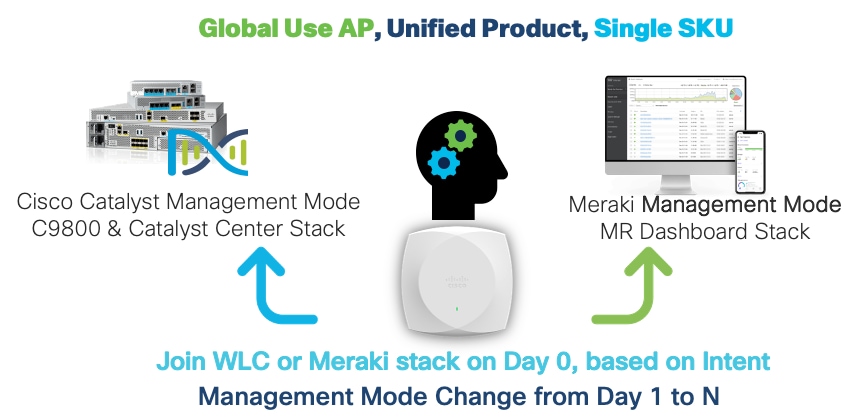
The Global Use AP simplifies the Cisco Wireless AP portfolio, by
1. Decoupling the AP PID/SKU from which geography (regulatory domain) they can be used.
2. Decoupling AP PID/SKU from the boot mode; that is, WLC or Meraki based.
Examples of PID/SKU (in the past):
C9130AXI-B (where “-B” denotes for US use only)
CW9166I-MR (where -MR denotes it will boot in Meraki mode). Throughout this guide, you will learn how the CW9178I is a wireless powerhouse that can take your network to the next level.
Note: The journey of simplifying by reducing the number of regulatory domains, by combining many countries into -ROW SKU, and a common hardware, where Day 1 to N migration from one management mode to another was made possible with Cisco Wi-Fi 6E Access Points.
Having a Unified Product brings in many benefits:
1. Simplified ordering – Customers and Partners do not have to worry about how or where the AP will be deployed.
2. Simplified deployment – Planning and installation teams just plug in the APs, Meraki Dashboard or WLC mode is auto detected. Dashboard can be used as PnP tool by partners.
3. Simplified lifecycle – Customers can freely move APs between WLC and Meraki mode. No need to call support. Simplified RMA and factory resets.
Map of a Global Use AP’s Journey
A fresh out of box Cisco Wireless CW917x AP, on Day 0, will try to determine if it has to connect to Meraki Dashboard or to a Catalyst 9800 WLC, by checking if it has a cloud connectivity and can reach a Meraki Network or else look for a Cisco wireless controller in the local network through DHCP, DNS, or L2 broadcast discovery mechanisms.
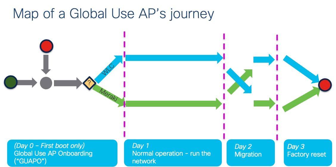
Once the AP, based on initial discovery, determines the Management Mode, boots the corresponding firmware image and connects to Meraki Dashboard or a Catalyst 9800 controller and performs operations in that mode. The AP can be migrated from one management mode to another, easily, through a very simple workflow from a Catalyst 9800 WLC or Meraki Dashboard. The AP can be factory reset, back to Out of box, i.e., Day 0 mode, at any time.
Note: When the Global Use AP connects to a Catalyst 9800 WLC, it has to determine the country in which it has to operate to adhere to local RF regulations. The Global Use AP can find the country it has to operate, in multiple ways.
1. The Cisco Wireless CW917x series APs have a built in GPS/GNSS module, that can help to determine the geo location.
2. For APs, deep inside a floor, where it cannot have a clear sky view, it can learn its country from a neighboring AP, which could be i) a legacy AP that is already connected to the same WLC or ii) another CW917x AP, which had obtained its location through GPS/GNSS, called the Anchor AP, by listening to the NDP messages that is transmitted over air. This is called Proximity based discovery.
3. For Air gapped customers, where method 1 or 2, does not work, the CW917x APs can be forced to obtain their country through a manual way of Regulatory Activation File, obtained from Meraki Dashboard and imported into Catalyst 9800 WLC.
All the methods are explained in detail in the subsequent section of this document.
Customer Scenario 1 – Meraki Customer
Here is an illustration of a customer, Mr. Miles, who is a Meraki customer, on how he onboards the CW917x series Global Use APs.
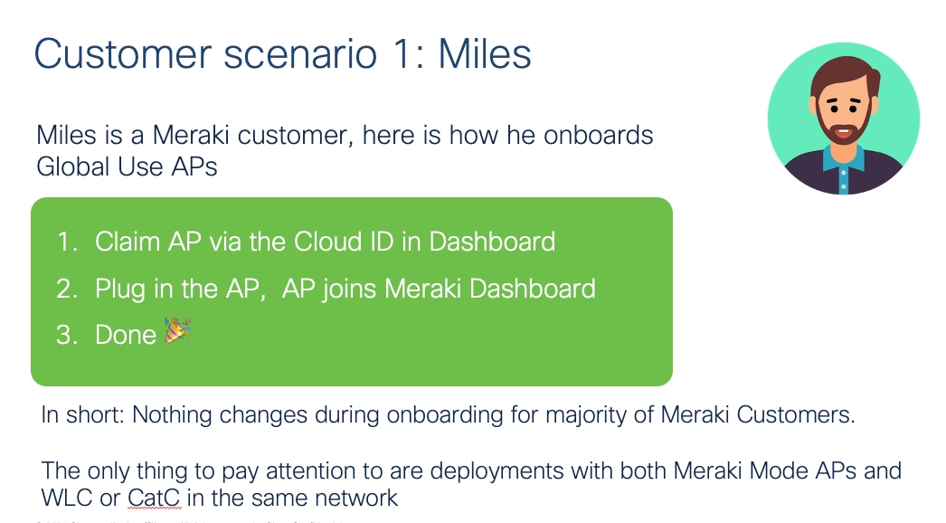
The experience will be exactly same like today.
Customer Scenario 2 – Catalyst WLC Customer
Here is an illustration of a customer, Ms. Catarina, who is a Catalyst WLC Customer on how she onboards the CW917x series Global Use APs.
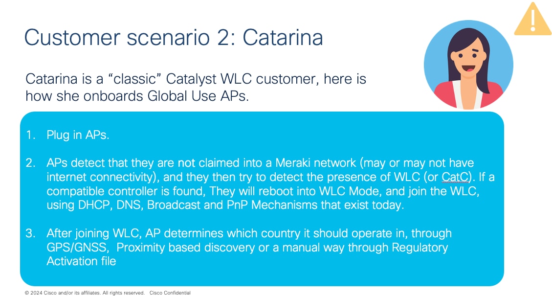
The experience will be mostly the same, with a few additional configurations that may be needed, depending on the deployment.
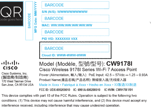
Starting with CW917x series of APs, the “Meraki Serial Number” has been renamed to “Cloud ID”. This change will reflect on the AP label, AP packaging, QR Code etc. The “Cloud ID” is used in the Meraki device claim workflow. In short, there is no functional change to how this is used in Meraki Dashboard.
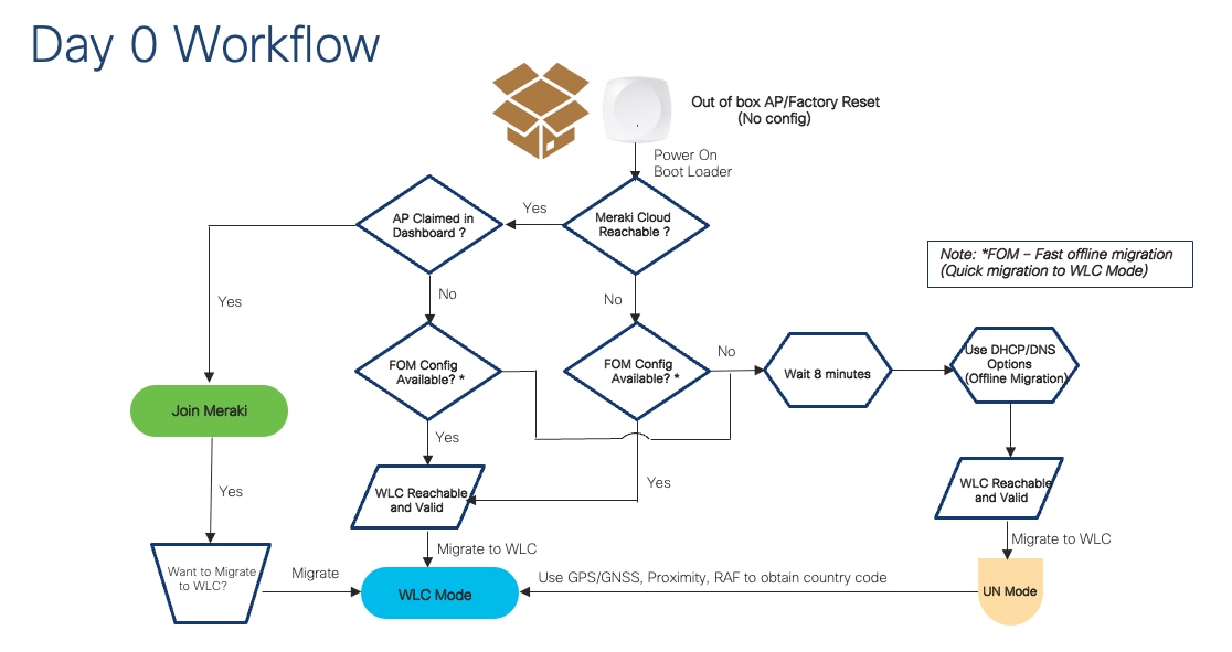
Day 0 Workflow: Technical Details and Configuration
This section walks through the workflow on how to onboard the CW917x Wi-Fi 7 Access Point to Meraki Dashboard and Catalyst 9800 Wireless LAN Controller.
Note: When the Wi-Fi 7 is powered on, fresh Out of the box or factory reset, the Day 0 firmware logic decides whether to Onboard to Meraki Dashboard or to Onboard to a Catalyst Wireless Controller. The Day 0 firmware has different versions. As of updates to this document in August 2025, there are two Global Use AP firmware versions that are available namely GUAP1.0 and GUAP1.1. GUAP1.1 has minor enhancements when compared to GUAP1.0. The initial set of Wi-Fi 7 Access Point hardware CW9178, CW9176I & D, CW9172I ships with GUAP1.0, whereas Wi-Fi 7 Access Point hardware CW9172H, CW9179F ship with GUAP1.1 as of August 2025. The specific differences in behavior of the different GUAP firmware versions are called out where applicable, in appropriate sections in the document below.
Note: GUAP1.1 is present in MR31.1.6 and above. If an out of box Wi-Fi 7 AP is allowed to connect to dashboard, even when unclaimed, it will upgrade to MR31.1.6 or above and get GUAP1.1. For unclaimed units, destined for WLC mode (mainly for CW9178, CW9176I&D and CW9172I), if they are allowed to connect to the internet, they will get GUAP1.1.
Intent: Onboard to Meraki Dashboard
If the intent is to, onboard CW917x series APs to Meraki dashboard, please make sure
1) There is internet connectivity from the CW917x AP to reach the Meraki cloud.
2) Devices are claimed in the Meraki Dashboard, either with Order number, Cloud ID or MAC Address.
3) There is no Catalyst 9800 Wireless Controller running IOS-XE version 17.15.2 or later that is present in the same VLAN as the CW917x AP.
4) There are no DHCP, DNS (including wildcard entry), or PnP configurations that can lead the CW917x AP to a Catalyst 9800 Wireless Controller.
Power on the CW917x series APs through PoE or Power Injector. The APs once boot up will reach the Meraki Cloud and present itself in the Dashboard.
Intent: Onboard to Catalyst Wireless Controller
If the intent is to, onboard CW917x series APs to Catalyst 9800 Wireless Controller, there are a couple of options:
Option 1: Where there is internet connectivity from the CW917x series APs and customer having a Meraki Dashboard account. Make the APs join the Meraki Dashboard and migrate the APs to WLC.
Option 2: Where there is no internet connectivity from the CW917x series APs. Employ discovery mechanisms like DHCP, DNS, Local status page (LSP), Broadcast (IPv4), Multicast (IPv6) or PnP to reach the Catalyst 9800 WLC.
The following sections walk through the details of different options.
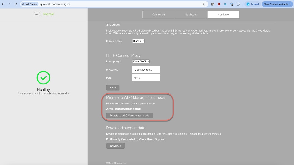
Option 1: Migrate through Meraki Dashboard
1. Add and claim the devices in a network in the Meraki Dashboard starting from Rel 31.1.5.1, either with Order number, Cloud ID or MAC Address.
2. Power on the CW917x series APs through PoE or Power Injector. Please allow a few minutes for the AP to boot up and reach Meraki Cloud and present itself in the Dashboard.
3. Meraki dashboard determines where the APs are located and sets country code accordingly.
4. Make sure Mesh is disabled on Network-wide -> Configure -> General -> Device Configuration -> Mesh. Note: Disabling Mesh is a requirement to migrate APs and it’s enabled by default in all new networks.
5. Make sure the configuration is up to date in the APs list before performing the migration in the next step. Reference: https://documentation.meraki.com/General_Administration/Cross-Platform_Content/Monitoring_Configuration_Updates_on_Cisco_Meraki_Devices#MR_Series_Access_Points
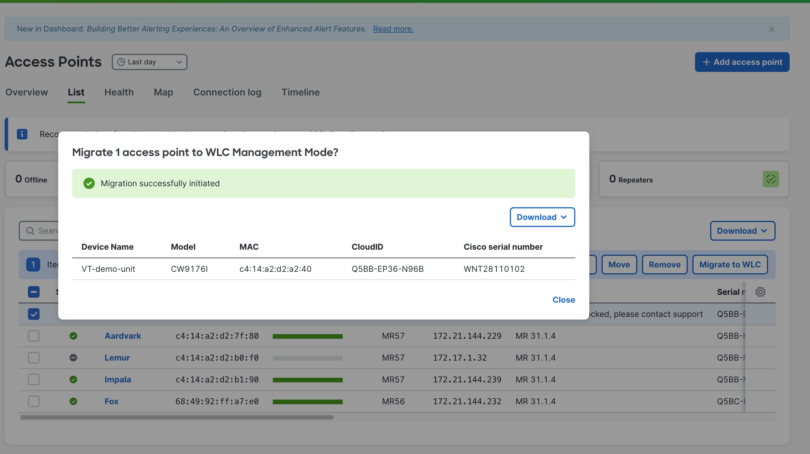
6. Select the APs that you want to migrate to and click on “Migrate to WLC”.
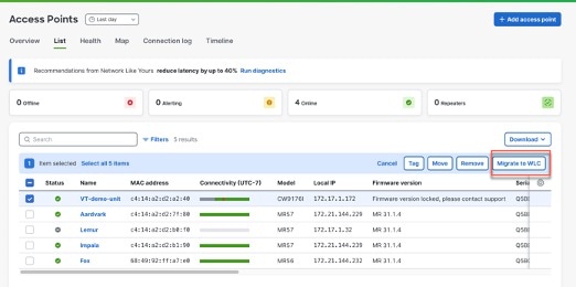
7. Confirm the migration.
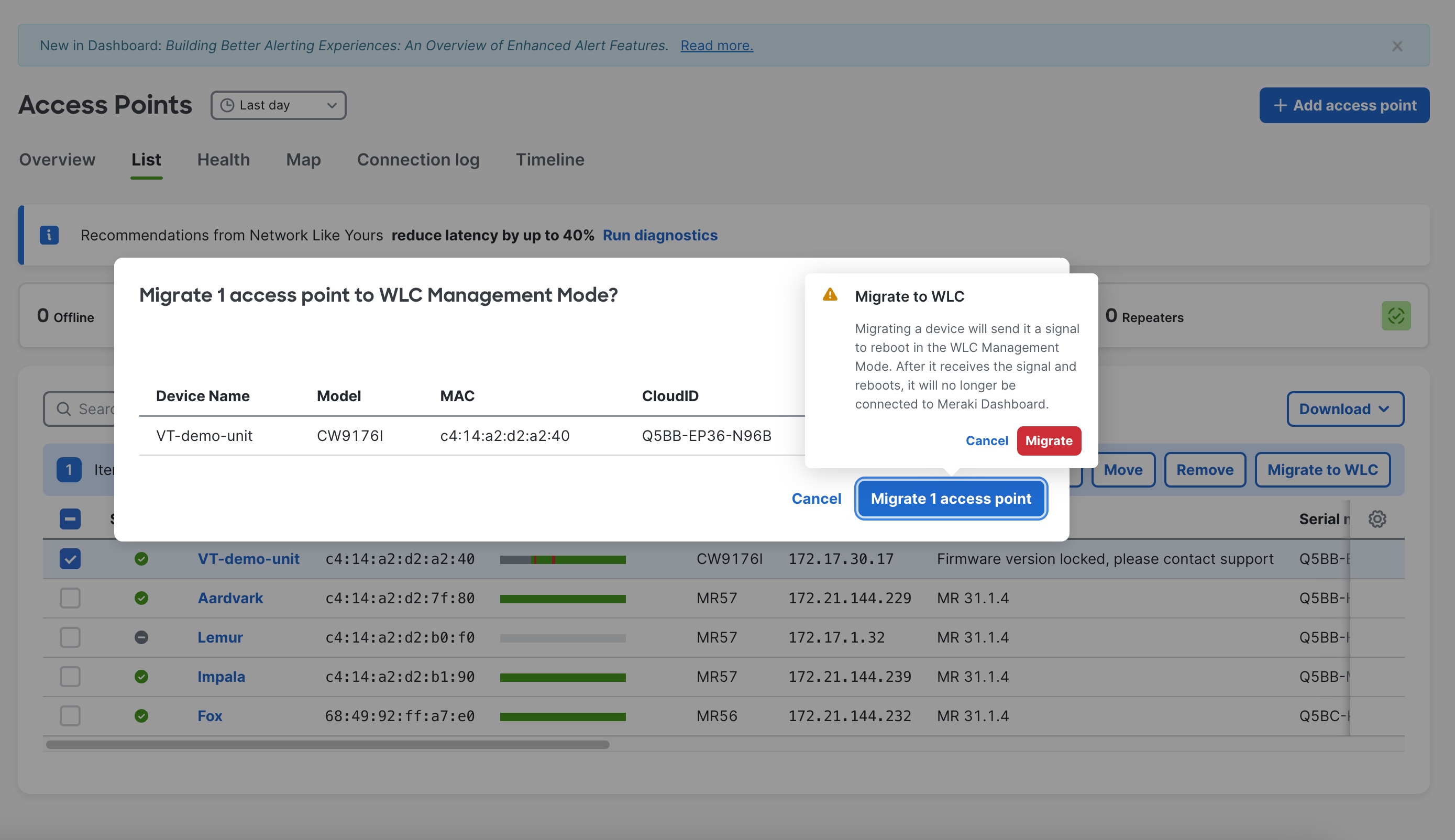
8. Once done, the Meraki dashboard will send an instruction to the Access Point to reboot in WLC Management Mode.
9. When the AP reboots and boots up with WLC management mode firmware image, it will do a CAPWAP discovery of the controller through the traditional mechanism of DHCP(IPv4/IPv6), DNS(IPv4/IPv6), Broadcast (IPv4), Multicast (IPv6) and join the WLC.
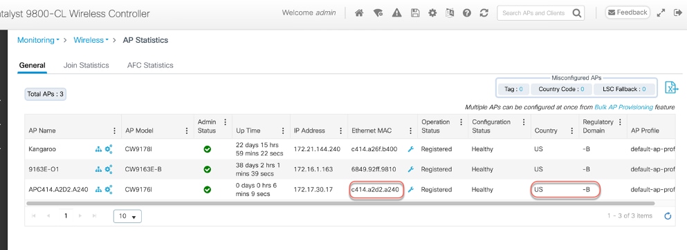
10. The country code is carried forward during migration. (No need for any additional steps or configuration needed to configure the country.)
Option 2: Migrate without Dashboard.
This is the scenario, when there is no internet connection, and the intent is to make the CW917x APs join the Catalyst 9800 WLC. This method is termed as “Offline Migration” or “Fast Offline Migration”,
Offline Migration uses traditional DHCP/DNS options and requires zero change on the existing network.
Note: For Offline Migration, the AP needs to wait for 8 minutes before it starts the migration to WLC mode.
Fast Offline Migration uses new DHCP/DNS options and will bypass the 8-minute wait timer.
Note: Without Fast Offline Migration, the CW917x AP will keep looking for cloud for 8 minutes. At the end of the 8th minute, it will check and confirm the WLC presence with the IP address it obtained through DHCP and DNS through CAPWAP Discovery/Response, before it migrates to the WLC Management mode. The 8-minute window is only for the very first time (in Day 0 mode), when the AP is trying to discover a cloud or WLC. Any subsequent reboot of the AP, say for example an image upgrade scenario, does not involve a wait time. The users can opt to use Fast Offline Migration techniques, where the period of 8 minute is not acceptable for Day 0 discovery of WLC.
Note: The pre-requisite is to have a Catalyst 9800 WLC with IOS-XE version 17.15.2 software for CW9178I, CW9176I & D1 Access Points and the WLC should be network reachable from APs subnet.
The order of priority for migration is as follows:
· Fast Offline Migration
o DHCPv4
o DHCPv6
o DNSv4
o DNSv6
· Local Status Page
o The AP can be manually migrated through the web interface or the Local Status Page of the AP within 8 minutes, when Fast Offline migration Options are not present.
· Offline Migration
o DHCPv4
o DHCPv6
o DNSv4
o DNSv6
o Broadcast/Multicast Discovery
Fast Offline Migration
1) DHCPv4
The option 43 string for DHCPv4 Fast offline migration is as follows:
· F3 <size> <IP array> Mode=<1|2>, where Mode = 1 -> Meraki and 2 -> Catalyst
where size is Number of WLCs *4 +1 (For one WLC – the size is 05 and two WLCs – the size is 09 and so on)
· Example String for one WLC.
o f305ac10011802 (“normal” option 43 “f104ac100118” becomes “f305ac10011802”)
§ Change type from f1 to f3
§ Change length from 04 to 05
§ Add the sub option at the end; 01 for Meraki, 02 for Catalyst
· IOS/IOS-XE configuration example for WLC discovery using DHCPv4:
ip dhcp pool vlan192
network 192.168.200.0 255.255.255.0
default-router 192.168.200.1
option 43 hex f305.ac10.0118.02
· Windows server configuration screenshot:
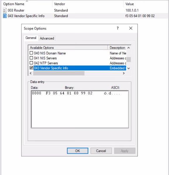
Note: At least one IP in the IP array must be either ICMP or CAPWAP reachable. The AP will check for ping response (ICMP or CAPWAP) from the WLC. If there is a response, the AP will migrate to WLC Management mode.
2) DHCPv6
The fast offline migration for DHCPv6 is Option 52 + Option 17
· Option 52 (standard): IPv6 array
· Add Option 17
o Enterprise ID = 29671; SubCode =1; Size =1; Mode = <1|2>, where Mode = 1 -> Meraki and Mode = 2 -> Catalyst vendor-specific 29671
· IOS/IOS-XE configuration example for WLC discovery using DHCPv6:
ipv6 dhcp pool vlan20
address prefix 2001:DB8:20:20::/64
capwap-ac address 2001:DB8:20:20::50
vendor-specific 29671
suboption 1 hex 02
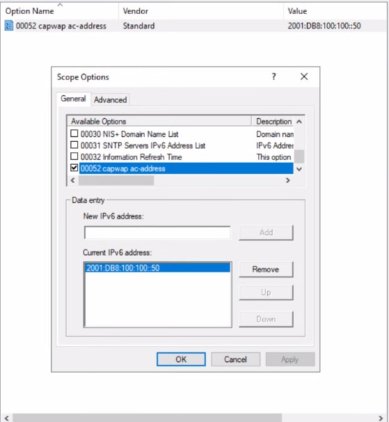
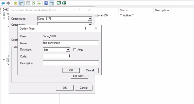
· Windows server configuration steps:
Option 52:
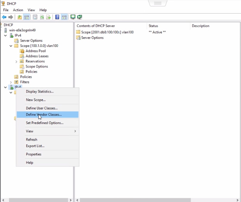
Option 17:
Step 1: Define Vendor Class.
Step 2: Assign a name. Enter the value 29671 for Vendor ID. Enter the ASCII value “Cisco Wireless AP CW9178I” in the text box for CW9178I platform.
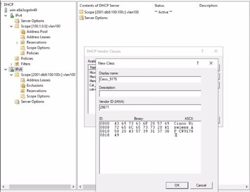
Note: For CW9176I, please use the ASCII string “Cisco Wireless AP CW9176I”.
For CW9176D1, please use the ASCII string “Cisco Wireless AP CW9176D1”
Step 3: Step predefined options.
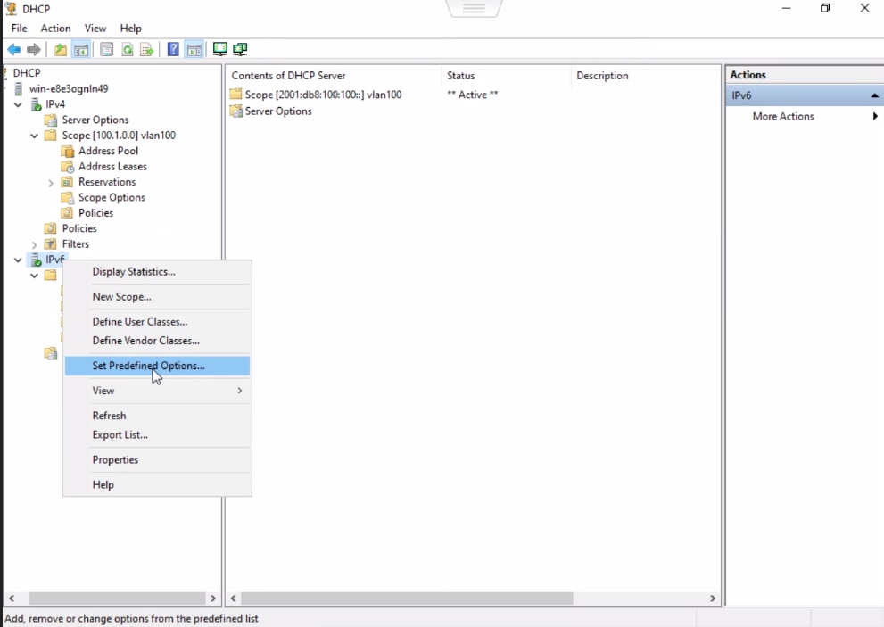
Step 4: Enter the value “1” in the Code field.
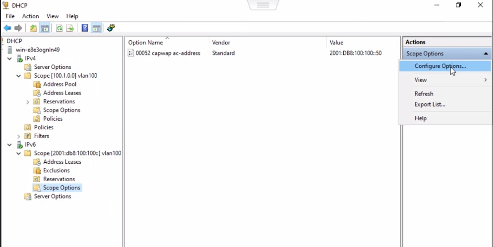
Step 5: Under the scope options, select Configure options.
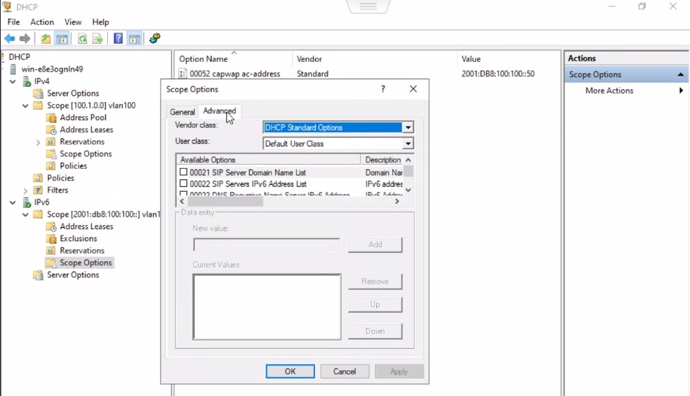
Step 6: Under the advanced tab, select the Vendor Class, created in Step 2.
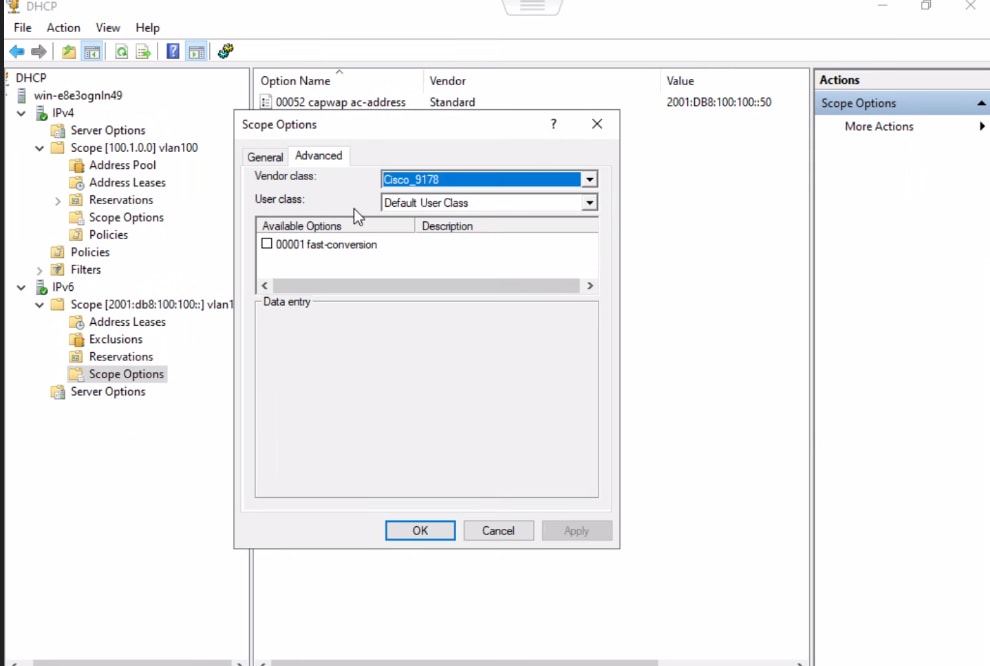
Step 7: Select the available options, and enter the value 0x2
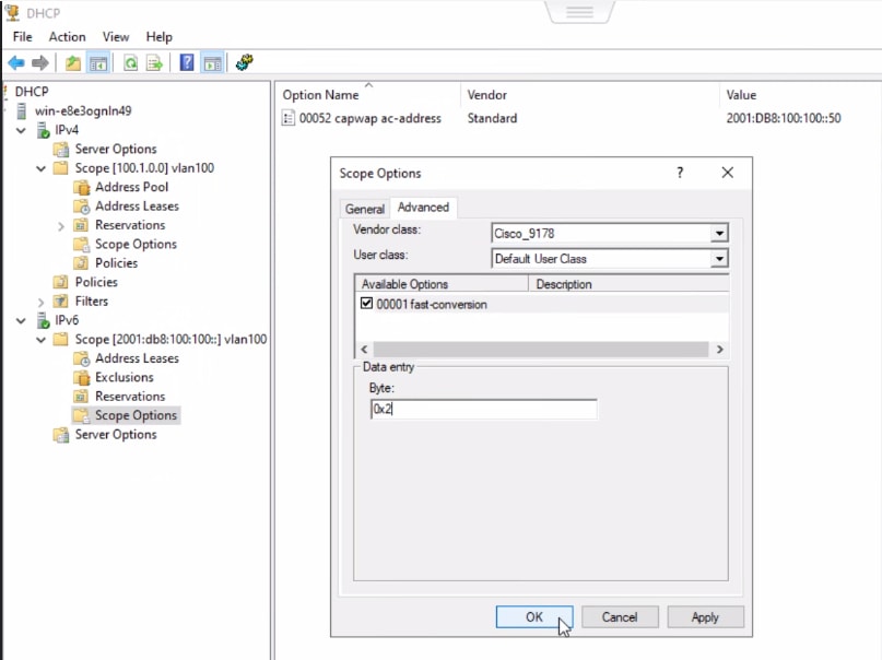
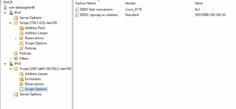
Note: At least one IP in the IP array must be either ICMP or CAPWAP reachable. The AP will check to ping the WLC. If there is a response, the AP will migrate to WLC Management mode, else it will try CAPWAP discovery.
Note: When both IPv4 and IPv6 (stateful) are present in dual stack, configure migration options in v4.
Note: When only IPv6 (stateful) is present, then only Fast Offline migration is supported (Option 17+52)
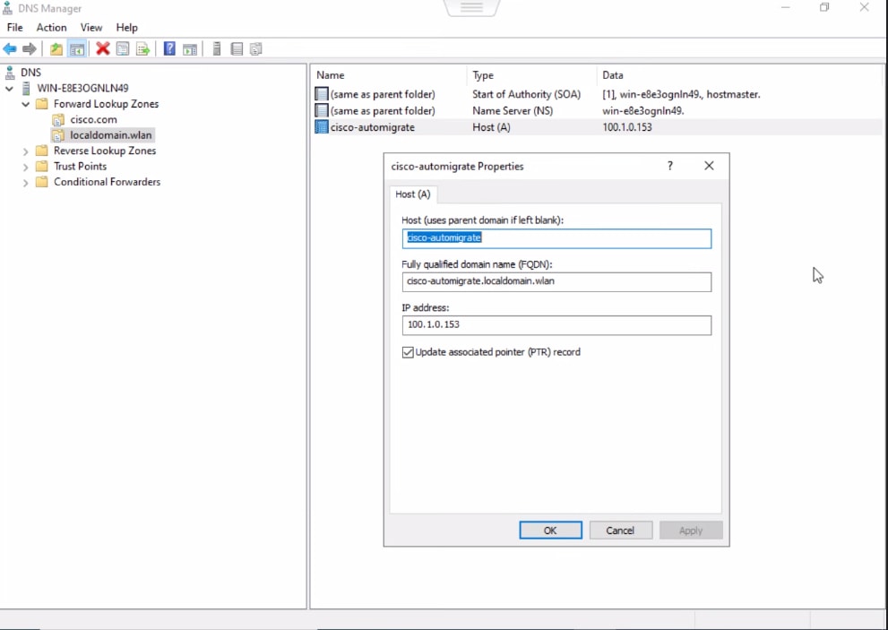
3) DNSv4/v6
The fast offline migration string for DNS for both v4 and v6 :
· Add the DNS entry (A record) cisco-automigrate.<domain> in the DNS server.
· The AP checks for the presence of DNS entry (AAAA record): cisco-automigrate.<domain>
If the DNS entry resolves, THEN, ping IP returned from DNS.
If ping success, then immediately migrate AP to WLC mode
If ICMP is blocked, then the AP tries CAPWAP reachable to WLC. If CAPWAP response is successful, then migrate AP to WLC mode.
· In firmware GUAP1.1, if the DNS entry cisco-do-not-automigrate.<domain> resolves, then the AP will not migrate to WLC mode.
Note: In firmware GUAP1.0, the AP checks only for cisco-automigrate.<domain> resolution. If the resolution is successful, then AP will do an ICMP ping to the WLC for reachability. If ping is successful, then migrate the AP to WLC mode.
· Windows server screenshots:
IPv4
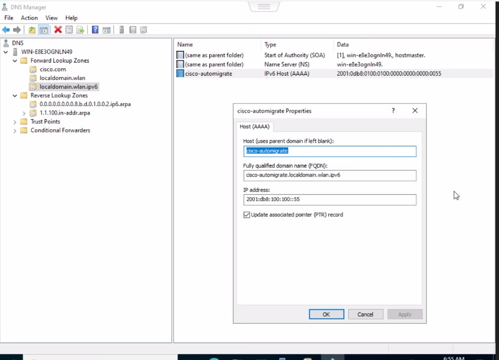
IPv6
Local Status Page
The CW917x series APs have a local status page that can be accessed to migrate the AP to WLC Management mode, when in Day 0 mode, during the 8-minute discovery period. Please refer to the document https://documentation.meraki.com/General_Administration/Tools_and_Troubleshooting/Using_the_Cisco_Meraki_Device_Local_Status_Page on how to access the Local Status Page.
From the Local Status Page, click on Migrate to WLC Management mode. This will trigger a reload of the AP, boot with WLC Management Mode firmware and proceed to discover WLCs.
Offline Migration
Once the 8-minute discovery window (to reach Meraki Cloud, Fast-Offline Migration and migration through Local status page) is over, the AP will resort to traditional discovery mechanisms of DHCP, DNS and Broadcast/Multicast.
The existing configuration used for CAPWAP discovery mechanisms in Cisco Wireless Controller deployments continues to apply.
Note: The DHCPv4 option 43 with type f2 used for EWC deployments can be used. However, the recommendation is to use standard option 43 values.
option 43 hex f205.c0a8.0a05.01
Deployments that employ PnP (Plug-N-Play) server to stage parameters to an access point, is supported as well, with CW917x Access Points in the Day 0 workflow. Onboarding through PnP Server is supported only in Offline Migration and is not supported in the Fast Offline Migration method.
Example configuration of DHCP scope with Option 43 for PnP.
ip dhcp pool vlan192
network 192.168.200.0 255.255.255.0
default-router 192.168.200.1
option 43 ascii 5A1D;B2;K4;|192.168.200.5;J8
In GUAP1.1 firmware release the following enhancements are made for Onboarding through PnP Server.
1. For DHCPv4, a liveliness check for the PnP server checks for successful response of HTTP/HTTPS GET /pnp/HELLO with 200. If the response is not successful, AP will not migrate.
2. For DHCPv6:
a. If the DNS entry resolves to cisco-do-not-automigrate.<domain>, then the AP does not migrate.
b. A liveliness check for the PnP server checks for successful response of HTTP/HTTPS GET /pnp/HELLO with 200. If the response is not successful, AP does not migrate.
3. DNS resolution of PNP server.
a. If the DNS entry resolves to pnpserver.<domain> and cisco-do-not-automigrate.<domain> does not resolve and liveliness check for the resolved DNS entry succeeds (i.e HTTP or HTTPS GET /pnp/HELLO with 200, then migration happens). If cisco-do-not-automigrate.<domain> is resolved or HTTP/HTTPS GET of /pnp/HELLO fails, then migration will not happen.
There are a few steps put in place to prevent accidental migration.
1. At least one IP in the IP Address array returned by DHCP option or the IP address of the resolved DNS entry should be CAPWAP reachable, which will trigger the bootloader to boot up the WLC Management mode firmware image for AP join. The CAPWAP response includes the WLC version image, which will be compared by the CW917x AP, to be a valid image, where it can join the WLC. This is done to prevent accidental migration, because of a response from a WLC, that’s not intended.
2. If the DNS entry cisco-do-not-automigrate.<domain> resolves to an IP address, then AP won’t migrate to WLC mode.
Note: The above method is valid only if the DNS method is configured. It’s not valid when other methods like DHCP and L2 discovery are present.
3. End user control through CLI. The end user can configure the CLI to prevent WLC to respond to Day 0 CAPWAP discovery requests by the CW917x APs. This way the end user can fine tune its config based on its own deployment specificities.
Configuration is done in AP Join Profile.
To “not respond” to CAPWAP Discovery:
C9800-L(config)#ap profile onboarding-prof
C9800-L(config-ap-profile)#no capwap-discovery onboarding
C9800-L(config-ap-profile)#exit
C9800-L(config)#
To “respond” to CAPWAP Discovery:
C9800-L(config)#ap profile onboarding-prof
C9800-L(config-ap-profile)#capwap-discovery ?
onboarding Configure CAPWAP onboarding related parameters
private Include private IP in CAPWAP Discovery Response
public Include public IP in CAPWAP Discovery Response
C9800-L(config-ap-profile)#capwap-discovery onboarding ?
all Configure automatic CAPWAP onboarding from Meraki based on both
unicast and broadcast discovery request
unicast Configure automatic CAPWAP onboarding from Meraki based on unicast
discovery request only
By default, WLC will accept only unicast requests for onboarding.
Note: If the CW917x APs must be in the same subnet as the WLC and use Broadcast (IPv4) or Multicast (IPv6) for discovery, then capwap-discovery onboarding should be set to “all”. Otherwise, the WLC will not respond to Broadcast/Multicast discovery requests.
Troubleshooting Day 0 Onboarding
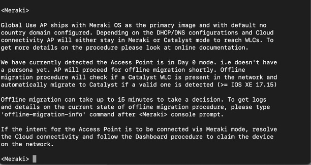
When the CW917x series AP is in Day 0 mode, the console will print the output shown below as a result to any input followed by a character return.
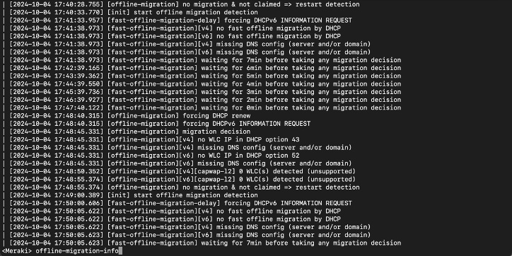
Type the command “offline-migration-info” on the <Meraki> prompt to get the details on the Day 0 onboarding process.
The “offline-migration-info” command is only available whilst the AP is in Day 0 mode.
Country Code and Regulatory Domain
The Wi-Fi 7 access points need a country code for them to operate in the country where they are deployed, and to meet the local regulatory compliance.
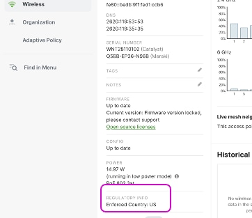
For APs operating in Meraki mode, the regulatory enforcement is done based on the Geo-IP location and network-wide setting.
Previously, for APs operating in WLC Mode, the regulatory enforcement was through individual SKU per country or territory. With CW917x series APs having a single SKU or PID, they can be deployed anywhere in the world, as the regulatory enforcement is not done in the hardware. These APs can determine their Country Code in one of the following ways:
GPS/GNSS – Obtain the geolocation through the integrated GPS/GNSS Antenna.
1. The CW9178/CW9176/CW9179 series AP have a built in GPS/GNSS. The CW9172I can have a GPS dongle attached to the USB port. They can obtain the geolocation coordinates, if they can get a clear sky view typically placed near a window to obtain the satellite signal. WLC maps the geolocation coordinates to the country. Till the time, the AP obtains the country code, it will have -UN as the regulatory domain.
2. Note: The CW9178/CW9176 series APs have an external GPS/GNSS antenna port. If the AP is not very close to a window, then an external GPS/GNSS antenna can be plugged into the AP to obtain the geolocation coordinates. The external antenna has a cable length of 10m (32.80 ft), so the AP can be placed upto 10m from the window or wall of the external Antenna.
3. Part number of the GNSS External Antenna: CW-ANT-GPS1-M-00
C9800-L#show ap summary
Number of APs: 1
CC = Country Code
RD = Regulatory Domain
AP Name Slots AP Model Ethernet MAC Radio MAC CC RD IP Address State Location
-------------------------------------------------------------------------------------------------------
AP-B2E0 4 CW9178I c414.a26f.b2e0 c414.a26f.b2f0 -- -UN 20.20.20.52 Registered default location
Once the WLC determines the country code, the AP will undergo a reload and join back with the country code.
*Oct 21 22:05:04.146: %APMGR_TRACE_MESSAGE-5-AP_COUNTRY_CODE: Chassis 1 R0/0: wncd: AP Name Wi-Fi7-AP-B2E0 Mac: c414.a26f.b2f0 Model CW9178I Type REVERSE_GEOCODING : SUCCESS: Resolve Country Code: [US]
*Oct 21 22:05:31.027: %CAPWAPAC_SMGR_TRACE_MESSAGE-5-AP_JOIN_DISJOIN: Chassis 1 R0/0: wncd: AP Event: AP Name: Wi-Fi7-AP-B2E0 Mac: c414.a26f.b2f0 Session-IP: 20.20.20.52[5272] 20.20.20.11[5246] Disjoined Max Retransmission to AP
C9800-L#show ap name Wi-Fi7-AP-B2E0 config general | inc Country
Country Code : US
Regulatory Domain Allowed by Country : 802.11bg:-A 802.11a:-AB 802.11 6GHz:-B
AP Country Code : US - United States
Country Code Resolution Method : GPS
C9800-L#show ap summary
Number of APs: 1
CC = Country Code
RD = Regulatory Domain
AP Name Slots AP Model Ethernet MAC Radio MAC CC RD IP Address State Location
-------------------------------------------------------------------------------------------------------
AP-B2E0 4 CW9178I c414.a26f.b2e0 c414.a26f.b2f0 US -B 20.20.20.52 Registered default location
Not all the APs need to obtain the GPS/GNSS signal. A few APs on a floor can obtain the GPS/GNSS signal and serve as Anchor APs. Then, the remaining APs that are located deep within the building can get their country code through Proximity-based discovery. This is covered in the next step.

Note: In some deployment scenarios, where there is no clear sky view, thick windows, close neighbor buildings, the AP could take a long time or never obtain a GPS/GNSS signal. In such scenarios, the other methods like Proximity, Migration or Regulatory Activation File could be used to obtain the country code and regulatory information for WLC Management mode. For Greenfield deployments, it’s recommended to use GPS/GNSS. If there are issues in obtaining the GPS/GNSS signal, as mentioned above, it’s recommended to use Migration through Meraki Dashboard.
Proximity based discovery – Learn from the nearby APs
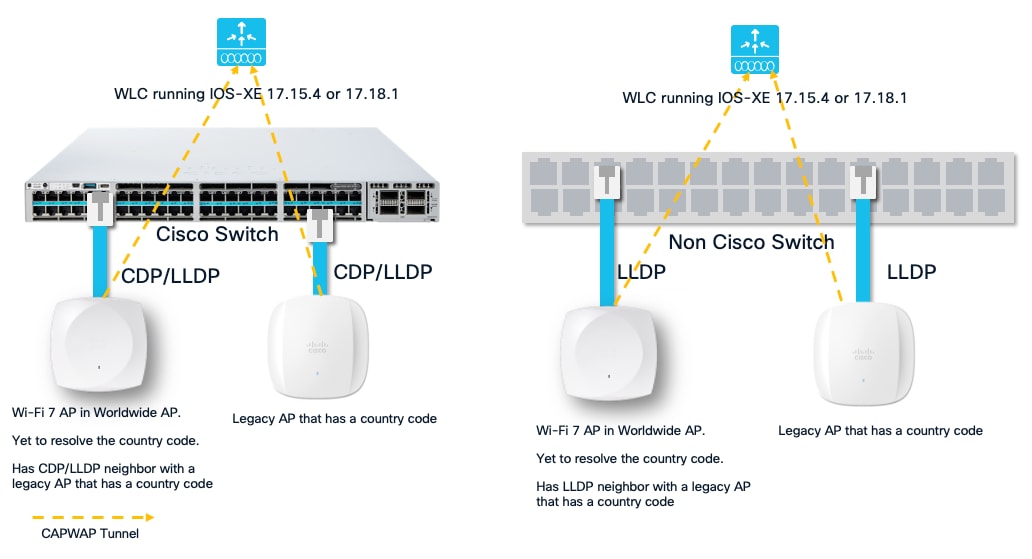
For brownfield deployments, where there is difficulty in obtaining the GPS/GNSS signal, the Wi-Fi 7 APs in worldwide mode can resolve the country code from pre-existing legacy APs on the floor connected to the same WLC. The proximity-based discovery works through
1. RF based NDP messages that the Wi-Fi 7 AP in worldwide mode can listen to the neighboring APs that has a country resolved (fully functional and capable of serving clients) are connected to the same WLC.
2. (Or) Through CDP/LLP based discovery mechanism, where a fully functional, client serving AP that has country code resolved and the Wi-Fi 7 AP in worldwide mode that is yet to obtain a country code are connected to the same switch and same WLC.
Note: CDP/LLDP based discovery mechanism is available from IOS-XE version starting 17.15.4 and 17.18.1.
The requirements for proximity-based discovery are:
1. Legacy APs (or) a Wi-Fi 7 AP that has obtained the country code through GPS/GNSS in the RF neighborhood, joined to the same WLC as the Wi-Fi 7 APs in worldwide mode, and
2. 2.4 GHz network enabled.
The Wi-Fi 7 APs listen to the RF NDP messages on the 2.4 GHz channels and learn the country code.
Note: Proximity based discovery will NOT work, if 2.4 GHz network is disabled. It’s mandatory to turn it on.
AND/OR
3. Legacy APs or a Wi-Fi 7 AP that has obtained a country code and the Wi-Fi 7 AP in worldwide mode, connected to the same switch and same WLC in IOS-XE 17.15.4 (or later in that release train) or 17.18.1 and later.
Country Code Learn through GPS/GNSS & Proximity
In the above scenario, there are a few APs, where they can obtain the GPS/GNSS signal and get the country code. There are also legacy APs present in the floor. The Wi-Fi 7 APs in the RF vicinity can learn their country code from the Wi-Fi 7 APs with GPS Module or from the legacy APs.
AP state before obtaining the country code:
C9800-L#show ap summary
Number of APs: 2
CC = Country Code
RD = Regulatory Domain
AP Name Slots AP Model Ethernet MAC Radio MAC CC RD IP Address State Location
-----------------------------------------------------------------------------------------------------------
AP-B2E0 4 CW9178I c414.a26f.b2e0 c414.a26f.b2f0 -- -UN 20.20.20.52 Registered default location
AP-E040 3 CW9176I 8c88.814f.e040 ecf4.0caf.6a60 US -B 20.20.20.51 Registered default location
In the example above, the AP named AP-E040 has it’s country code and regulatory domain and the AP named AP-B2E0 is in the nearby proximity, which will learn it’s country code from AP-E040. This process takes just few minutes.
The APs undergo a reload, when they learn their country code from the neighboring APs.
*Oct 21 21:49:57.664: %APMGR_TRACE_MESSAGE-5-AP_COUNTRY_CODE: Chassis 1 R0/0: wncd: AP Name Wi-Fi7-AP-B2E0 Mac: c414.a26f.b2f0 Model CW9178I Type PROXIMITY : SUCCESS: Resolve Country Code: [US ]
*Oct 21 21:49:57.665: %APMGR_TRACE_MESSAGE-6-WLC_APMGR_INFO: Chassis 1 R0/0: wncd: Info : - c414.a26f.b2f0 Setting country code to Access Point, Access Point will reboot and join back to WLC
AP state after obtaining the country code:
C9800-L#show ap summary
Number of APs: 2
CC = Country Code
RD = Regulatory Domain
AP Name Slots AP Model Ethernet MAC Radio MAC CC RD IP Address State Location
-----------------------------------------------------------------------------------------------------------
AP-B2E0 4 CW9178I c414.a26f.b2e0 c414.a26f.b2f0 US -B 20.20.20.52 Registered default location
AP-E040 3 CW9176I 8c88.814f.e040 ecf4.0caf.6a60 US -B 20.20.20.51 Registered default location
C9800-L#show ap name Wi-Fi7-AP-B2E0 config general | inc Country
Country Code : US
Regulatory Domain Allowed by Country : 802.11bg:-A 802.11a:-AB 802.11 6GHz:-B
AP Country Code : US - United States
Country Code Resolution Method : Proximity
Country Code Learn through CDP/LLDP Proximity
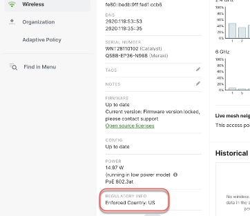
Figure 11 Obtaining Country code through CDP/LLDP Proximity
In the above scenario, a Wi-Fi 7 AP has joined a Cisco 9800 running IOS-XE 17.18.1 and happens to be a CDP or LLDP neighbor of another AP, which has its country code resolved. Both the APs are connected to the same switch and have joined the same WLC. They need not be in the same RF neighborhood.
AP state before obtaining the country code:
C9800-L#show ap summary
Number of APs: 2
CC = Country Code
RD = Regulatory Domain
AP Name Slots AP Model Ethernet MAC Radio MAC CC RD IP Address State Location
-----------------------------------------------------------------------------------------------------------
AP-B2E0 4 CW9178I c414.a26f.b2e0 c414.a26f.b2f0 -- -UN 20.20.20.52 Registered default location
AP-E040 3 CW9176I 8c88.814f.e040 ecf4.0caf.6a60 US -B 20.20.20.51 Registered default location
In the example above, the AP named AP-E040 has it’s country code and regulatory domain and the AP named AP-B2E0 as a CDP neighbor connected to the same switch, but can’t hear through RF. This process takes just few minutes.
C9800-L#show ap cdp neighbors
Number of neighbors: 2
AP Name AP IP Neighbor Name Neighbor IP Neighbor Port
---------------------------------------------------------------------------------
AP-B2E0 20.20.20.52 C9200 20.20.20.1 TenGigabitEthernet1/0/5
AP-E040 20.20.20.51 C9200 20.20.20.1 TenGigabitEthernet1/0/4
Note: CDP/LLDP proximity is supported only when the neighbor APs are in the same switch. CDP/LLDP proximity is not supported across switches.
The country code resolution can be checked from the C9800 WLC using the following command :
show logging process wncd internal start last 30 minutes | proximity to-file bootflash:proximity_logs.txt
AP state after obtaining the country code:
C9800-L#show ap summary
Number of APs: 2
CC = Country Code
RD = Regulatory Domain
AP Name Slots AP Model Ethernet MAC Radio MAC CC RD IP Address State Location
-----------------------------------------------------------------------------------------------------------
AP-B2E0 4 CW9178I c414.a26f.b2e0 c414.a26f.b2f0 US -B 20.20.20.52 Registered default location
AP-E040 3 CW9176I 8c88.814f.e040 ecf4.0caf.6a60 US -B 20.20.20.51 Registered default location
C9800-L#show ap name Wi-Fi7-AP-B2E0 config general | inc Country
Country Code : US
Regulatory Domain Allowed by Country : 802.11bg:-A 802.11a:-AB 802.11 6GHz:-B
AP Country Code : US - United States
Country Code Resolution Method : Proximity
Through Migration
APs migrated from Meraki Dashboard will retain the country code they were operating in.
For Greenfield customers, where 1) there are no legacy AP deployments, 2) deployment restrictions that makes it difficult to obtain GPS/GNSS signal and 3) easy workflow of migrating the APs to WLC mode for Day 0 and obtain country information, it’s recommended to use the Migration method. Meraki dashboard determines where the APs are located and sets the country code accordingly.
The workflow steps were explained in the earlier section of Day 0 Workflow -> Intent: Onboard to Catalyst Wireless LAN Controller -> Option 1.
APs migrated through Migration method, will have the Country Code Resolution Method set as Installed via Meraki Dashboard.
C9800-L#show ap name Wi-Fi7-AP-B2E0 config general | inc Country
Country Code : US
Regulatory Domain Allowed by Country : 802.11bg:-A 802.11a:-AB 802.11 6GHz:-B
AP Country Code : US - United States
Country Code Resolution Method : Installed via Meraki Dashboard
4. Regulatory Activation File – Download a Regulatory Activation File (RAF) from Meraki Dashboard, that can be installed on WLC.
For Air gapped deployments, where there is no way to obtain GPS/GNSS signal, no legacy APs present in the network and where the APs cannot reach the cloud due to policy restrictions by the organization, the country code can be obtained in a manual way through the Regulatory Activation File from the Meraki Dashboard.
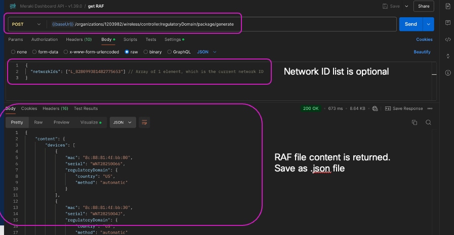
You can either automate the Regulatory Activation File (RAF) generation via API and scripting or do it manually.
To manually generate the Regulatory Activation File (RAF):
1. Claim the order or Cloud ID in the Meraki Dashboard.
2. Assign AP to a network. AP does “not” have to connect to dashboard.
3. Generate the Regulatory Activation File (RAF).
4. Copy RAF to WLC and install it.
Note: To generate an RAF file, you need a Meraki Dashboard account. You can create a free Meraki Dashboard account to generate the RAF file. You do not need to purchase a license for this.
To create a Meraki Dashboard account and claim the devices to generate a RAF file, do the following:
1. Create a Meraki Dashboard account. The following document walks through the steps to create a Meraki Dashboard Account, Organization and Network(s).
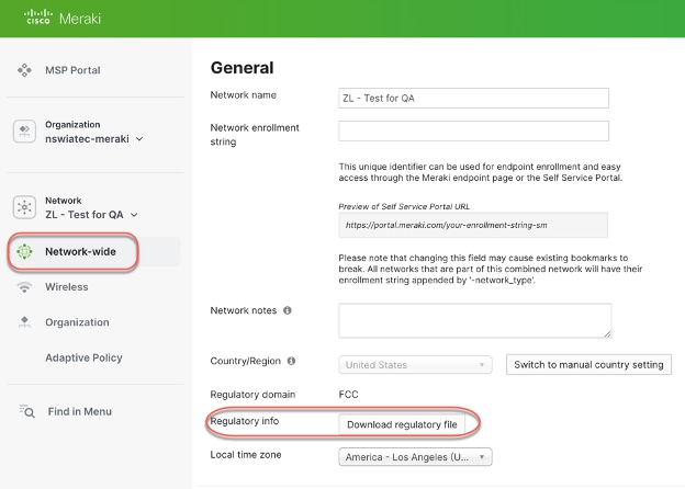
2. Once the network is created, configure the country/region setting in the Meraki dashboard for your network. Navigate to Network-wide à Configure à General à Network Location and select the appropriate country from the drop down. Repeat this for all the networks and configure the appropriate country to which the Network belongs.
3. The next step is to claim the Meraki access point in the Meraki dashboard. Navigate to Organization à Inventory, then click “Claim” and enter the order number or Cloud-ID, one per line and click “Claim Device”
4. Add the Access Points to the appropriate Network (if more than one). Navigate to Network-wide à Configure à Add devices.
Note: There is no need to make the APs join the Meraki Dashboard for RAF generation.
Now, generate the RAF. This file contains information for all networks that the current user has write permission to.
The RAF can be generated from Network Wide à Configure à General à Regulatory Info in the Meraki Dashboard. This will generate a JSON file.
This will download the JSON file to your desktop. Import this JSON file into the Cisco Wireless Controller.

Upload the RAF JSON file in the WLC from Administration à Regulatory Activation.

Once uploaded, click Apply. This applies the country code to the applicable APs that have joined and any new APs that will join the WLC. The APs that have joined the controller and are in worldwide mode, will undergo a reload.
Note: If CLI is used to upload the regulatory file, please move the file to bootflash:/regulatory folder. If “regulatory.json” is the file that is getting uploaded to C9800 through CLI, make sure the file is present in the regulatory folder.
C9800-L#dir bootflash:regulatory | s .json
If the file is not present in the bootflash/regulatory folder, then an error message is displayed about the non-existent file.
C9800-L#ap regulatory activation file regulatory.json
% Error: Regulatory activation file not found
T2=File “regulatory.json” is moved to directory folder:
C9800-L#copy bootflash:regulatory.json bootflash:regulatory/
Destination filename [regulatory/regulatory.json]?
Copy in progress...C
8035 bytes copied in 0.021 secs (382619 bytes/sec)
C9800-L#dir bootflash:regulatory
Directory of bootflash:/regulatory/
1479858 -rw- 8035 Jul 23 2025 21:19:57 +00:00 regulatory.json
CLI command to apply and clear the AP regulatory activation:
C9800-L#ap regulatory activation ?
apply Apply regulatory domain configuration
clear Clear AP mac to country mapping records
file Regulatory domain configuration file
C9800-L#ap regulatory activation file regulatory.json
C9800-L#ap regulatory activation apply (This command is needed to make the regulatory domain configuration effective)
The following command displays AP regulatory activation details:
C9800-L# show ap regulatory activation ?
all Show AP regulatory activation details for all APs
mac Show AP country mapping details of particular AP
all
C9800-L# show ap regulatory activation all
Regulatory Activation file Meta-data
------------------------------------
Date Created : 2024-10-22T00:40:06Z
Created By : xxx@email.org
Device count : 11
Organization Id : 821110
AP MAC Serial Number Country code
----------------------------------------------------
6849.9201.a4e0 WNH264801RQ US
6849.927a.4490 KWC271505U1
8c88.814f.e040 WNT282500HK US
c414.a2d2.b090 WNT281300XY US
c414.a2fb.04c0 WNT2820002R
c414.a2fb.3370 WNT2822006D US
c414.a2fb.38c0 WNT2822008W US
cc9c.3ee7.82b0 WNH260700TW
cc9c.3ee8.75c0 WNH261600HD
cc9c.3eec.1cf0 WNH26160034 US
AP MAC Serial Number Country code
----------------------------------------------------
e0cb.bc97.0f87
The AP can be factory reset to Out-of-Box, Day 0 Mode using 1) the reset button on the AP 2) through AP CLI.
Factory Reset via reset button on AP
To perform a factory reset:
1. Unplug the AP.
2. Hold the reset pin.
3. Power on the AP.
4. Hold the reset button until the LED changes color as listed in the table below.
| Reset Option |
Reset pin hold time |
LED Status |
| 1. Mode indication |
~ 5 sec |
· Blink green = Meraki Mode · Blink blue = Catalyst Mode |
| 2. Config reset |
> 10 sec |
Solid white |
| 3. Full reset (maintains management mode) |
> 20 seconds |
Orange |
| 4. FIPS reset (Catalyst mode only) |
> 30 seconds |
Solid red |
| 5. Factory reset (back to global use AP onboarding) |
> 60 seconds |
Solid pink |
| 6. Abort reset |
> 90 seconds |
NA |
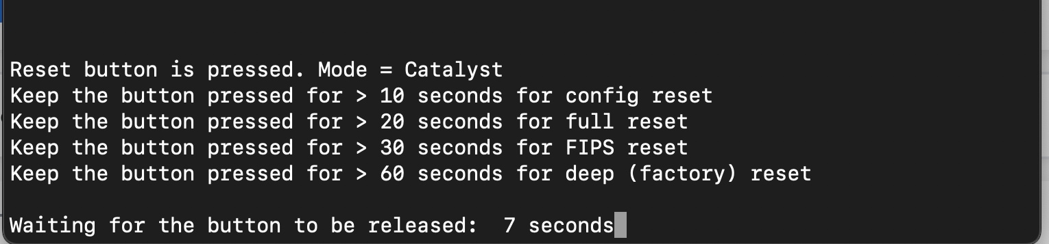
The console now displays the options as well as the reset pin hold time duration.
Reset button is pressed. Mode = Catalyst
Keep the button pressed for > 10 seconds for config reset
Keep the button pressed for > 20 seconds for full reset
Keep the button pressed for > 30 seconds for FIPS reset
Keep the button pressed for > 60 seconds for deep (factory) reset
Waiting for the button to be released: 7 seconds
This is a unified behavior across Catalyst and Meraki Mode. No change for customers used to Catalyst APs, but different for Meraki.
CLI to erase config, country and factory-reset
AP-B2E0#capwap ap erase
all Erase all AP config except country code
country Reset country code on AP.
factory-reset Factory reset the AP.
static-ip Erase static IP/DNS config
static-ipv6 Erase static IPv6/DNS config
The factory-reset option fully wipes and brings the AP to the out-of-box, Day 0 Mode.
The country erase option clears the country config alone and can be used if the AP’s location changes to a different country or re-evaluate its country.
1. CW9178I Hardware Installation Guide
2. CW9176I Hardware Installation Guide
3. CW9176D1 Hardware Installation Guide
4. CW9178I AP Deployment Guide