Cisco Wireless CW9172 Series Wi-Fi 7 Access Point Deployment Guide
Available Languages
Bias-Free Language
The documentation set for this product strives to use bias-free language. For the purposes of this documentation set, bias-free is defined as language that does not imply discrimination based on age, disability, gender, racial identity, ethnic identity, sexual orientation, socioeconomic status, and intersectionality. Exceptions may be present in the documentation due to language that is hardcoded in the user interfaces of the product software, language used based on RFP documentation, or language that is used by a referenced third-party product. Learn more about how Cisco is using Inclusive Language.
- US/Canada 800-553-2447
- Worldwide Support Phone Numbers
- All Tools
 Feedback
 Feedback
Cisco Wireless 9172 Access Points Series overview
The Cisco® Wireless 9172 series Wi-Fi 7 Access Points provide a seamless entry into next-generation wireless networking, delivering reliable, high-performance connectivity for environments like boutique hotels, student housing, retail stores, healthcare clinics, remote work hubs, and distributed business locations such as satellite offices, regional branches, and logistics hubs. The Cisco Wireless 9172 series Wi-Fi 7 Access Point has a penta-radio architecture providing the full capability of Wi-Fi 7 Features based on 802.11be amendment such as 4K Modulation, Multi Link Operation (MLO), 320-MHz channel width, preamble puncturing, Multi Resource Units, compressed block ACK enhancements of up to 512 MPDUs and Wi-Fi Protected Access 3 (WPA3) security, all while being able to leverage advanced RF visibility with Cisco CleanAir® Pro together with an artificial intelligence and machine learning (AI/ML)-driven scanning radio.
The Cisco Wireless 9172 series Wi-Fi 7 Access Point is a unified product with one SKU, that can be deployed with a Cisco Catalyst Wireless LAN Controller or Meraki Cloud based deployments. The CW9172 access point can be deployed anywhere in the world with a single SKU and avoids the need to buy a region or country specific SKU based on regulatory domain.

The Cisco Wireless 9172 AP supports the entire Cisco Catalyst wireless stack functionality with Cisco DNA Center (Automation and Assurance), Cisco Spaces (Location and IoT), Identity Services Engine (security), and more. Throughout this guide, you will learn how the CW9172 is a wireless powerhouse that can take your network to the next level.
The Cisco Wireless 9172 series Access Points have two platform variants
● CW9172I – Indoor Access Point with omnidirectional antennas, typically mounted on ceiling
● CW9172H – Wall plate, Indoor Access Point with omni-directional antenna and LAN ports for wired connections, typically mounted on wall.
Table 1. Cisco® Catalyst® Wireless 9800 Series controller software support matrix
| Supported IOS XE releases |
|
| CW9172I |
Cisco IOS XE 17.15.2b and later |
| CW9172H |
Cisco IOS XE 17.17.1 and later |
Supported controller platforms
CW9172 series APs are supported with the following Catalyst 9800 Series Controllers:
● 9800-H1
● 9800-H2
● 9800-M
● 9800-80
● 9800-40
● 9800-L
● 9800-CL
Note: Embedded wireless controller on AP (EWC) functionality is not supported on the CW9172 series, both as an active EWC or a subordinate AP.
Table 2. CW9172I At a Glance
| Capability |
Details |
| Product ID |
CW9172I – Indoor access point with omnidirectional antennas CW9172H – Wall Plate, Indoor access point with omnidirectional antennas |
| Scale |
256 clients per radio |
| Serving Radio |
● 2.4 GHz (Slot 0), 2x2:2 spatial streams
● 5 GHz (Slot 1), 2x2:2 spatial streams
● 6 GHz (Slot 2), 2x2:2 spatial streams (or) CW9172I Only
● 2.4 GHz (Slot 0), 2x2:2 spatial streams
● 5 GHz (Slot 1), 4x4:4 spatial streams
Note: CW9172I can operate as dual-radio or Tri-radio with Tri-radio as the default mode.
|
| IoT Capabilities |
● Dedicated 2.4 GHz IoT Radio
|
| Scanning Radio |
Yes |
| Wi-Fi 7 Features |
● 4K QAM
● 320 MHz Channel Width
● Multi-Link Operation
● Preamble Puncturing
● Multi Resource Units
● Compressed Block Ack with 512 MPDUs
● UL Triggered OFDMA
|
| Wi-Fi 6 Features |
● MU-MIMO
● OFDMA
● BSS Coloring
● TWT
|
| Uplink Port |
1xPOE-IN 2.5 Gig mGig Ports |
| LAN Ports (CW9172H) |
2x 1 Gig LAN Ports 1x 1 Gig Lan port with 802.3af PoE output 1x Passthrough (RJ45) Port |
| Interface |
mGig0, Console, USB 2.0 |
| Antenna |
Integrated, Omnidirectional |
| Dimensions |
CW9172I: 7.8x7.8x2.1 inches (20x20x5.3 cm) CW9172H: 5.1x7.0x1.0 inches (13x18x2.6 cm) |
| Weight |
CW9172I: 1.9 lb (874g) CW9172H: 1.16 lb (572g) |
| USB |
CW9172I Only 4.5 W Output |
| SSIDs |
● 2.4 GHz: 16
● 5 GHz: 16
● 6 GHz: 16
|
| MTBF |
CW9172I
● 25°C: 842,342 hrs
● 50°C: 567,000 hrs
CW9172H
● 25°C: 912,409 hrs
● 50°C: 349,710 hrs
|
| Environment |
● Nonoperating (storage) temperature: -40° to 158°F (-40° to 70°C)
● Nonoperating (storage) altitude test: 25°C (77°F) at 16,000 ft (4863 m)
● Operating temperature: 32° to 122°F (0° to 50°C) 40-50C derated
● Operating humidity: 10% to 95% (noncondensing)
● Operating altitude test: 45° C (113° F) at 4205m (13.8K ft)
● Humidity:10% to 90% non-condensing
|
| Antenna Gain |
CW9172I
● 2.4 GHz: 4dBi
● 5 GHz: 5 dBi
● 6 GHz: 6dBi
CW9172H
● 2.4 GHz: 3 dBi
● 5 GHz: 6 dBi
● 6 GHz: 5 dBi
|
Table 3. Serving Radio Specifications
| Mode |
2.4 GHz Slot 0 |
5 GHz (Slot 1) |
6 GHz (Slot 2) |
| CW9172I, CW9172H Tri-radio 6SS |
● 2x2:2SS
● (20 MHz)
|
● 2x2:2SS
● (20/40/80/160 MHz)
|
● 2x2:2SS
● (20/40/80/160/320 MHz)
|
| CW9172I Dual-radio 6SS |
● 2x2:2SS
● (20 MHz)
|
● 4x4:4SS
● (20/40/80/160 MHz)
|
NA
|
The Cisco Wireless 9172 series AP is interoperable with the following network management and security solutions.
Table 4. Software Interoperability
| Catalyst 9800 |
Cisco Catalyst Center |
Cisco Spaces: Connector |
ISE |
| 17.15.2b |
3.1.3 |
Release 3 |
3.4 |
| 17.17.1 |
3.1.3 |
Release 3 |
3.4 |
CW9172 AP can operate in the following AP Modes.
1. Local
2. FlexConnect
3. Monitor
4. Sniffer
5. Fabric/SDA
6. Site Survey
Note: OEAP Mode is not supported in the Wi-Fi 7 Series Access Points. Hence CW9172 does not support OEAP Mode.
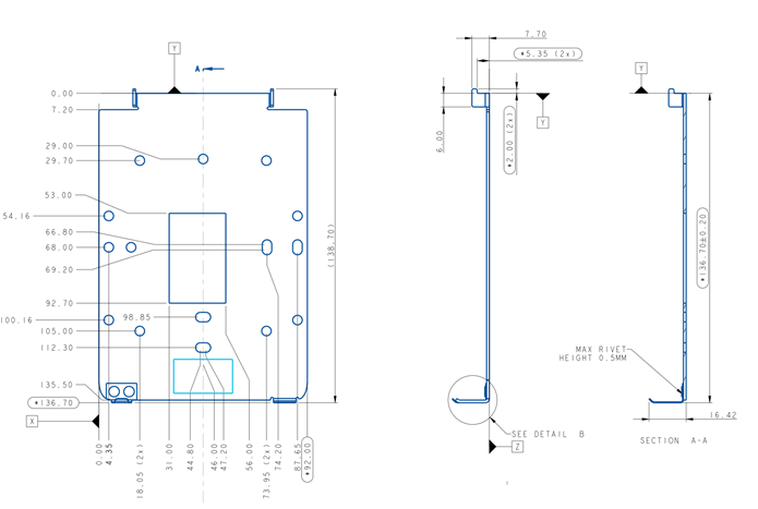
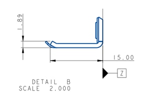
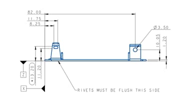
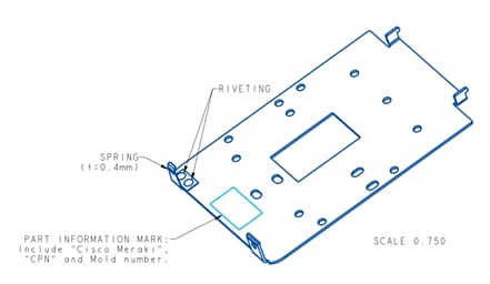
Mechanical design
The CW9172I & H has an altogether modern design which is aesthetically appealing allowing you to identify it among other APs instantly.


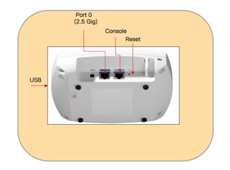
The following figure depicts the ports and reset button on the CW9172I:
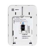
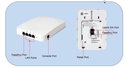
The following figure depicts the ports and reset button on the CW9172H.
CW9172I
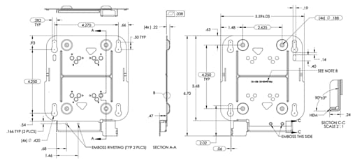
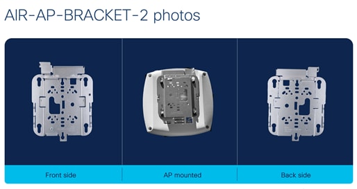
The CW9172I is compatible with AIR-AP-BRACKET-1 mounting bracket (default option) and Cisco Universal AIR-AP-BRACKET-2 mounting bracket. This AP is also compatible with the AIR-AP-T-RAIL-R and AIR-AP-T-RAIL-F for T-rail drop ceiling. These brackets are the same AP brackets provided for all Tier 2 and 3 enterprise-class APs for more than 15 years. This backward compatibility streamlines the day-0 process for brownfield deployments, allowing the CW9172I to be mounted on existing brackets. In addition, the CW9172I can be mounted using the AIR-CHNL-ADAPTER clip for channel-rail ceiling grid profiles.
For more details on mounting the access point, refer the following documents:
● Cisco Wireless CW9172I Hardware Installation Guide
● Access Point Mounting Instructions
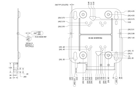
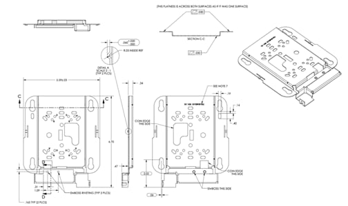
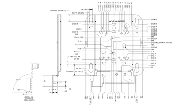
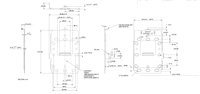
The following figures provide details about the AIR-AP-Bracket-1 and AIR-AP-Bracket-2 for reference:

The CW9172H has a new mounting bracket CW-MNT-H1 which will be default wall mounting option. It is also compatible with the legacy Meraki Mount MA-MNT-MR-H1A and Cisco Catalyst mount AIR-AP-BRACKET-4.
The CW9172H has an accessory option to allow the access point to be placed horizontally on a desk or secure the LAN ports.
● Desktop Accessory (CW-ACC-SPACER1-00).
This accessory is meant to be used in installations where additional cabling outlets are needed without having to use additional wall plates, thus making deployments aesthetically pleasing.
● Port Lock Accessory (CW-MNT-H3-00)
The accessory is meant to be used in installations where physical cable security is needed to prevent individuals from attempting to connect or disconnect wired devices to/from the CW9172H LAN Access Ports. This allows for organizations to securely implement wired guest services with ease of mind knowing that the physical cabling infrastructure will not be tampered with.
● Wall Spacer Accessory (CW-ACC-DESK1-00)
The accessory is meant to be used in installations where additional cabling outlets are needed without having to use additional wall plates, thus making deployments aesthetically pleasing.
For more details on mounting the CW9172H access point to the wall or to mount with accessories, see CW9172H Hardware Installation Guide.
Cabling
The use of proper cable types will enhance the performance of the CW9172 series access point. Since this AP has 2.5 Gbps ports, it is recommended to use either CAT5e, CAT6 or CAT6a. CAT5e can support speeds up to 5 Gbps and CAT6, CAT6a can support speeds up to 10 Gbps.
The table below lists the various cable types that can be used with the CW9172 AP.
Table 5. Software Interoperability
| Cable type |
Speeds |
Maximum Length |
| CAT5e |
5 Gigabit |
328 feet (100 meters) |
| CAT6 |
1/2.5/5 Gigabit |
330 feet (100 meters) |
| 10 Gigabit |
164 feet (50 meters) |
|
| CAT6a |
10 Gigabit |
330 feet (100 meters) |
The following table depicts the radio, port, USB performance, and maximum power draw based on the AP’s input power. For optimal performance, 803.2bt is required.
Note: It’s recommended to use CAT6 or CAT6a cables for the best performance.
Table 6. PoE specifications for CW9172I
| Power Source |
Number of Spatial Streams |
2.4 GHz Radio (Slot 0) |
5 GHz Radio (Slot 1) |
6 GHz Radio (Slot 2) |
2.5 Gig Port |
USB |
IoT/Scan Radio |
| 802.3af (PoE) |
1 |
1x1 |
Disabled |
Disabled |
1G |
Disabled |
Y |
| 802.3at (PoE+) (Tri Radio) |
6 |
2x2 |
2x2 |
2x2 |
2.5G |
Disabled |
Y |
| 802.3at (PoE+) (Dual Radio) |
6 |
2x2 |
4x4 |
NA |
2.5G |
Disabled |
Y |
| 802.3 bt (PoE++ /UPOE) (Class 5) (Tri Radio) |
6 |
2x2 |
2x2 |
2x2 |
2.5G |
Yes/4.5W |
Y |
| 802.3 bt (PoE++ /UPOE) (Class 5) (Dual Radio) |
6 |
2x2 |
4x4 |
2x2 |
2.5G |
Yes/4.5W |
Y |
Table 7. PoE specifications for CW9172H
| Power Source |
Number of Spatial Streams |
2.4 GHz Radio (Slot 0) |
5 GHz Radio (Slot 1) |
6 GHz Radio (Slot 2) |
2.5 Gig Port |
PoE Out |
IoT/Scan Radio |
| 802.3af (PoE) |
1 |
1x1 |
Disabled |
Disabled |
1G |
No |
Y |
| 802.3at (PoE+)
|
6 |
2x2 |
2x2 |
2x2 |
2.5G |
No |
Y |
| 802.3 bt (PoE++ /UPOE) (Class 5) |
6 |
2x2 |
2x2 |
2x2 |
2.5G |
Yes (15.4W) |
Y |
Global use AP
The CW9172 is a unified global use access point, that can be deployed with Cisco Catalyst 9800 Wireless LAN Controller (Catalyst Management Mode) or cloud-based deployment with Meraki Wireless Stack (Meraki Management Mode) anywhere in the world, where it’s certified to use without the need for a regulatory domain specific SKU. This gives customers flexibility and investment protection when they decide to deploy the access point in any of the deployment models.
The CW9172 AP can discover the management mode based on the customer’s intent by the presence of cloud connectivity and discovery options based on DHCP and DNS. Once the Access Point discovers the controller, it can obtain its country specific regulation through:
1. Proximity-based discovery
2. Regulatory activation file for air-gapped deployments.
For detailed explanation and configuration options to achieve the desired management mode discovery, see Cisco Wireless Global Use Access Points Deployment Guide.
Dual-Band mode in CW9172I
The CW9172I has three clients serving radios. It can operate in a Tri-band Tri-Radio mode (2.4/5/6 GHz) as 2x2:2 in each of the radios or in Dual-band Dual-Radio mode (2.4/5 GHz) with 2x2:2 on the 2.4 GHz radio and 4x4:4 on the 5 GHz radio.
When all the networks are enabled globally (i.e., 2.4, 5 and 6 GHz), the CW172I will join as a tri-band in tri-radio mode. If the 6-GHz network is either disabled due to regulatory restrictions, or manually disabled, the CW9172I will function as 2x2:2 in 2.4 GHz radio and 4x4:4 in 5 GHz radio. The CW9172I can be manually converted to a 4x4:4 in 5 GHz, even when all the networks are enabled, by manually disabling the 6 GHz radio of the access point.
To individually convert the AP to a Dual-band mode, navigate to Configuration > Wireless > Access Points > 6 GHz Radio and disable the Admin Status of the AP. On disabling, an AP reboot warning pops up. Checkbox the “Reboot on Update & Apply to Device”, select OK and apply Update & Apply to Device. The AP will reload, with 6 GHz radio disabled and 5 GHz radio operating as 4x4 radio chain with 4 spatial streams.
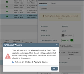
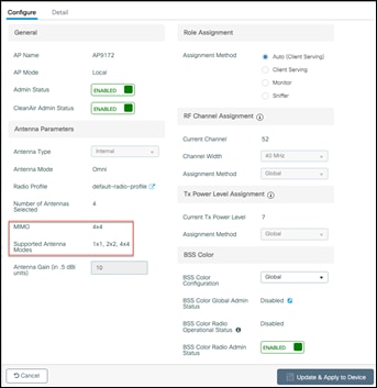
Figure 13. Status of Radio chain after conversion to Dual-band mode.
To convert the AP back to tri-band, tri-radio mode, enable the Admin Status of the AP on the 6 GHz radio.
RLAN Ports in CW9172H
The CW9172H has three LAN Ports labeled 1 through 3. These LAN Ports may be used for extending connectivity to Wired devices.
The LAN Ports can negotiate for 1 Gig speed.
Port 1 has PoE out of max 15.4 Watts and can be used to power up devices like Wired Cameras that can operate with a PoE.
Note: The CW9172H AP needs an IEEE 802.3bt Class 5 power source, for PoE out on Port 1.

Figure 14. CW9172H Port View
To configure Remote LANs (RLANs) on a Cisco Catalyst 9800 Series Wireless Controller (WLC) for a CW9172H access point, you will use the RLAN policy profile. This involves creating an RLAN profile with specific settings, then associating it with the AP's profile. You will also need to configure the security settings for the RLAN, including 802.1x and web authentication.
1. Create an RLAN Profile.
Navigate to Configuration > Tags & Profiles > Remote LAN in the WLC GUI. Click Add to create a new RLAN Profile.
Enter a profile name and the RLAN ID and set it enabled.
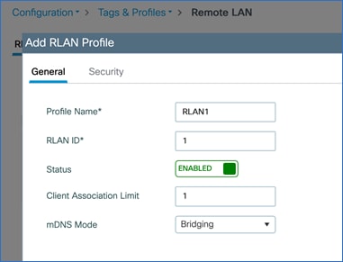
Figure 15. Add RLAN Profile
Add the security configurations in the Security Tab
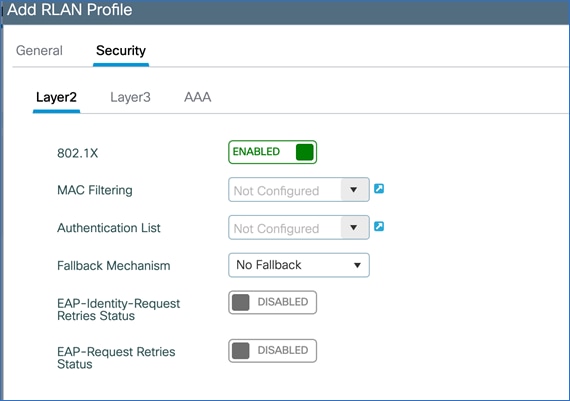
Figure 16. Configure security parameters for RLAN Profile
Apply the configuration.
Navigate to Configuration > Tags & Profiles > Remote LAN in the WLC GUI. Click Add to create a new RLAN Policy.
Enter a policy name and set the status to Enabled. Configure the desired parameters in the General, Access Policies and Advanced tabs. Apply the configuration.

Figure 17. Add RLAN Policy
Once the RLAN Profile and Policy is created, the next step is to assign the RLAN Profile and Policy to a Policy Tag.
2. Assign the RLAN Profile and Policy to Policy Tag.
Navigate to Configuration > Tags & Profiles > Tags > Policy Tab.
Add a new Policy Tag or Edit an existing Policy Tag. If it is a new Policy Tag, scroll down to the WLAN Policy Maps section. Add the WLANs and the Policy Profile. Once done with adding the WLAN-Policy Maps, scroll down to add the RLAN-Policy Maps. Add the RLAN Profile and RLAN Policy to each port. This could be the same RLAN Profile and Policy for all the ports or can be customized for each port.
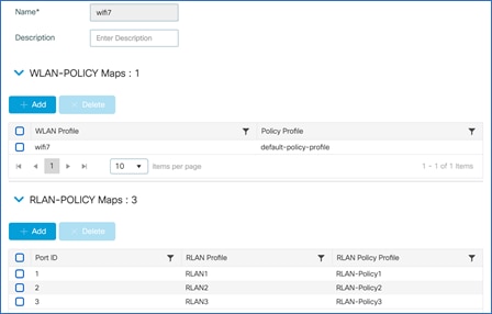
Figure 18. Assign RLAN Policy
3. Assign the Policy Tag with RLAN-POLICY to the AP.
Now assign the Policy Tag with the WLAN and RLAN Policy maps to the CW9172H AP in the AP Configuration Page. (Navigate to Configuration > Wireless > Access Points. Select the CW9172H Access Point and in the General Tab, select the Policy Tag that has the RLAN Policy Map). The AP will reboot, whenever there is a change in Policy, Site or RF Tags.
4. Enable RLAN Ports on the AP.
Navigate to the Interfaces Tab of the AP. Scroll down the page and enable “Status” for each of the Port.

Figure 19. Edit AP Interface
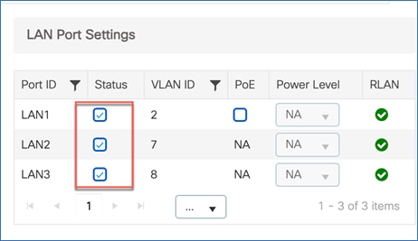
Figure 20. Enable LAN in LAN port settings
Note: It is possible to have a mix of Centrally Switched and Locally Switched RLAN Ports. The following table covers the combination supported.
Table 8. AP mode and RLAN ports
| Power Source |
RLAN Central Switching |
RLAN Local Switching |
RLAN Central DHCP |
RLAN Local DHCP |
| Local Mode |
X |
|
Yes |
No |
|
|
X |
|
Yes |
|
| FlexConnect Mode
|
X |
X |
Yes |
No |
|
|
X |
Yes |
Yes |
1. When RLAN Port is Centrally Switched, Local DHCP is not supported.
2. Each RLAN Port supports a maximum of 4 clients.
3. RLAN does not support Multihost and Multidomain mode.
4. Multicast works in both Local & FlexConnect mode with Central & Local Switching.
RLAN Security:
RLAN Ports supports Open, MAB, 802.1X and WebAuth security types.
The following table lists the security combination supported when the AP is in Local or FlexConnect Mode and the RLAN Ports are Centrally or Locally Switching.
Table 9. AP Mode and RLAN Ports Security Combination
| AP Mode |
Switching |
DHCP |
MAB |
802.1X |
WebAuth |
| Local/Flex |
Central |
Central |
Yes |
Yes |
Yes |
| Local/Flex |
Local |
Local |
Yes |
Yes |
Yes |
| Local/Flex |
Local |
Central |
Yes |
Yes |
Yes |
Getting started with Wi-Fi 7
The IEEE developed the 802.11be amendment (Extremely High Throughput) to the 802.11 standard, which the Wi-Fi alliance adopted the draft v3.0, as the basis for Wi-Fi 7 certification. The Wi-Fi 7 alliance planned to adopt a subset of features from the 802.11be amendment as part of their Release 1 certification, that was made available in January 2024. A second release with support for an incremental set of features is planned for Release 2 certification, slated for December of 2025.
Wi-Fi 7 offers many enhancements that will benefit enterprises, as well as end users by increasing speeds up to four times compared to Wi-Fi 6. In addition, it offers super low latency, more robust connection, higher spectral efficiency, better interference mitigation, more power-saving techniques, better roaming experience, and increased security.
Wi-Fi 7 offers the following features.
● 4096 QAM (4K-QAM) – It encodes the number of bits in a sub-carrier to 12 bits, in contrast to 10 bits encoded in a sub-carrier for 1024 QAM in Wi-Fi 6. This introduces two new MCS rates, MCS 12 and 13. 4K QAM helps with up to 20% higher data transmission rates. This is an optional feature for Wi-Fi 7 certification.
● 320 MHz Channel Width (at 6 GHz) - The max channel width is doubled to 320 MHz when compared to 160 MHz in Wi-Fi 6. With 1200 MHz spectrum space available in the 6 GHz band, it is possible to achieve 3x 320 MHz wide channels. This is an optional feature for Wi-Fi 7 certification.
● Multi-Link Operation (MLO) – MLO enables aggregation of multiple bands or channels. With MLO, the Wi-Fi 7 Access Point and client devices can associate and simultaneously exchange traffic on multiple bands (or multiple channels in the same band if the access point has a dual 5 GHz radio). The distribution of traffic on different bands helps achieve higher throughput, reduced latency and improves reliability.
● Preamble Puncturing – Preamble puncturing allows access points to ‘carve out’ or ‘puncture’ a portion of channel width that is affected by interference, resulting in the remaining channel being used for data transmission. The feature ensures optimal Wi-Fi performance especially when there is interference.
● Multiple Resource Unit (MRU) – MRU improves the OFDMA technology. OFDMA allows sub-carriers in a channel bandwidth to be grouped into smaller portions called “Resource Units,” (RUs). These individual RUs are assigned to different stations, which allows access points to serve them simultaneously during uplink and downlink transmissions. In Wi-Fi 6, access points assign only a single RU to each wireless client. Wi-Fi 7 allows multiple resource units (MRUs) to be assigned to each wireless client. MRUs enhance spectral efficiency and interference mitigation.
The next sections detail the configuration steps needed to enable 802.11be and the other features.
In the Cisco Catalyst 9800 Controller GUI, navigate to Configurations > Radio Configurations > High Throughput, and choose Enable 11be for the bands where 802.11be is needed, and click Apply.
Note:
1. It is recommended to enable this for all the bands.
2. If 802.11be is enabled, MLO gets enabled too. This MLO setting is not independent and of the 802.11be configuration.
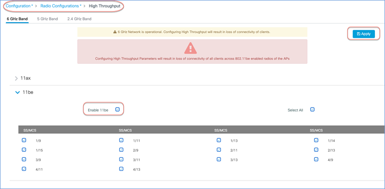
Figure 21. Enable 11be for different bands in the Cisco Catalyst 9800 controller GUI
The channel width for the 6 GHz band, could be set to a maximum of 320 MHz in DBS channel width, for RRM to issue out a 320 MHz channel width, when its algorithm finds it conducive to issue a larger channel width.
From Configuration > Tags & Profiles > RF/Radio, edit the 6 GHz RF Profile to include 320 MHz as the max channel width.
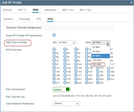
Figure 22. Update RF Profile to Set DBS Channel Width in the Cisco Catalyst 9800 controller GUI
A specific AP could be statically configured for 320 MHz on the access point configuration page.
Navigate to Configuration > Wireless > Access Points > 6 GHz Radios, select the AP, change the RF channel assignment to Custom and select 320 MHz as the channel width.
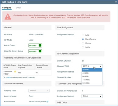
Figure 23. Set RF Channel Width in the Cisco Catalyst 9800 controller GUI
Preamble puncturing is supported for 80 MHz or higher channel widths. For an 80 MHz, only 20 MHz is allowed to the punctured. The following table lists the allowed preamble puncturing options.
Table 10. Software Interoperability
| Channel Width |
Allowed Puncturing |
| 20 and 40 MHz |
Puncturing not allowed |
| 80 MHz |
20 MHz |
| 160 MHz |
20 or 40 MHz |
| 320 MHz |
40, 80 or 40 + 80 MHz |
To enable preamble puncturing, navigate to Configuration > Tags & Profiles > RF/Radio > edit the RF Profile of the 5 GHz and 6 GHz bands and enable Preamble Puncturing under the 802.11be tab.
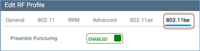
Figure 24. Edit RF Profile to Enable Preamble Puncturing in the Cisco Catalyst 9800 controller GUI
Wi-Fi 7 mandates the support for WPA3 and Enhanced Open (based on OWE) along with Protected Management Frame (PMF) for the clients to operate in 802.11be data rates and features like MLO. AKM 24 and 25 are added for WPA3-Personal. Additionally, Wi-Fi 7 requires beacon protection for both the AP and the Wireless Clients. With MLO, security needs to be established across all the links of a multi-link association. The security requirements are for Wi-Fi networks to be more secure and protect against cyber attacks.
The following table lists the security requirements for Wi-Fi 7 and comparison with previous Wi-Fi generations.
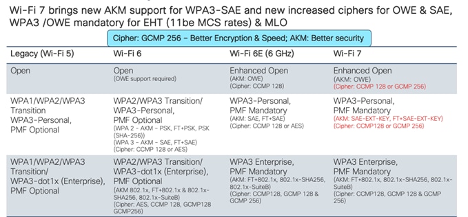
Figure 25. AKM Support
The security requirements for Wi-Fi 7 may necessitate a design change of the WLANs in the current deployment. There are a few options that the customer can consider, while implementing Wi-Fi 7.
● Option 1 – Reconfigure the existing WLANs to WPA3/Enhanced Open, along with the required AKMs and Ciphers – i.e., one SSID for all radio policies. While this makes the WLAN most secure, there are practical difficulties in implementation, as many existing clients may not support WPA3 and PMF.
● Option 2 – Add new SSIDs with the new security requirement for Wi-Fi 7 and have the newer clients associate to this SSID. This is an easy and flexible approach. The downside to this is maintaining additional SSIDs.
● Option 3 – Migrate the SSIDs to Transition Mode –WPA3 Transition. This is a conservative approach, taking one step to make the WLANs more secure and allowing newer clients with WPA3 security and older clients with WPA2 security to co-exist.
In the below section, you can find the configuration details for Option 3.
● Requirements for Wi-Fi 7: AKM 24 or 25, Cipher CCMP128 or GCMP 256.
● Recommendation: Configure WPA3 Transition (WPA2 + WPA3 Mixed Mode).
Configure the SSID to be WPA2 + WPA3 security type. Select AKM as PSK, SAE and SAE-EXT-KEY. Cipher as CCM128 and GCMP256. PMF as Optional. Use the same password.
Note: If FT is enabled, select FT+PSK, FT+SAE and FT+SAE-EXT-KEY.
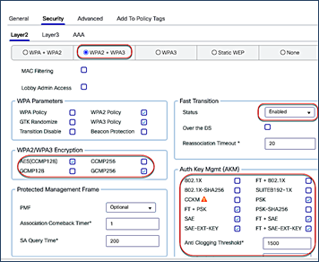
Figure 26. Configure WPA3 Transition (WPA2+WPA3 mixed mode) in the Cisco Catalyst 9800 controller GUI
● Wi-Fi 7 clients connect with WPA3/SAE-EXT-KEY or WPA3/FT-SAE-EXT-KEY with PMF
● Wi-Fi 6E clients connect with WPA3/SAE or WPA3/FT-SAE with PMF
● Wi-Fi 6 clients that support WPA3 connect with WPA3/SAE or WPA3/FT-SAE with PMF in 2.4 /5 GHz bands.
Note:
● Wi-Fi 7 needs AKM 24 or 25 as per specification. The initial clients in the market seem to negotiate 11be rates/MLO even with AKM 8 & 9. This may change in the future when client driver implementation gets stricter.
● If old clients that still use WPA1 are present in the network, then the recommendation is to have those clients in a separate SSID.
Requirements for Wi-Fi 7: AKM 3 or 5, Cipher CCMP128 (For most common deployments)
Recommendation: Configure WPA3 Transition (WPA2 + WPA3 Mixed Mode).
Configure the SSID to be WPA2 + WPA3 security type. Select AKM as 802.1x-SHA256 and 802.1x.
Note: If FT is enabled, select AKM as FT+802.1x.
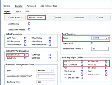
Figure 27. Configure WPA3 Transition (WPA2+WPA3 mixed mode) in the Cisco Catalyst 9800 controller GUI
On the client side that supports WPA3, configure WPA3 Enterprise. Wi-Fi 7 clients will use the settings to connect to any band with MLO. For Wi-Fi 6E clients, they will prefer connecting to 6 GHz band and Wi-Fi 6 clients will connect to 5 GHz or 2.4 GHz band. For clients that do not support WPA3, configure a WPA2 profile.
Note: Clients with outdated drivers may have difficulty associating with WPA3 Transition Mode. It is recommended to update the drivers and test the clients in the environment.
Note: WPA3 specs do not allow OWE Transition and recommends the use of OWE for Wi-Fi 6E and Wi-Fi 7. It is recommended to configure an OWE only security for deployments involving Wi-Fi 6E and Wi-Fi 7.
The Cisco Catalyst 9800 GUI now displays the MLO capability and client statistics. From the main dashboard or Monitoring > Clients, select a client listed in the Protocol column as “11be (MLO)”.
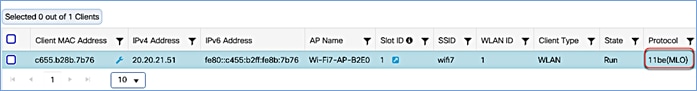
Figure 28. View Client Statistics in the Cisco Catalyst 9800 controller GUI
In the 360 view, the client’s MLO capability is indicated along with the number of radio slots it is associated with. In the example below, the client is associated with 2 radio slots.
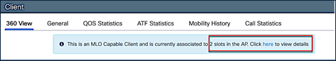
Figure 29. View Client’s MLO Capability and Associated Radio Slots in the Cisco Catalyst 9800 controller GUI
Click on the link to view the details, client properties, security information and client statistics.

Figure 30. View Client Statistics in the Cisco Catalyst 9800 controller GUI
Migration between management modes
The Cisco Wireless 9172 AP is a global use unified access point and can convert from the Cisco Catalyst management mode to the Meraki management mode and vice versa. This Unified Product gives you the flexibility of being deployed in a Catalyst 9800 WLC based deployment or cloud-based Meraki deployment. It also provides investment protection for the future in case you want to switch between the two management options anytime from day 1 to day N.
Starting with Wi-Fi 7 access points, the Meraki Serial Number has been renamed to “Cloud ID”. There is no functional change to how this was used in the previous generation product.
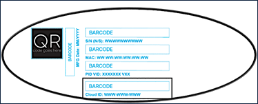
Figure 31. Cloud ID
The CW9172I & H can be converted from Catalyst Management Mode to Meraki Management Mode through a simple workflow in C9800 WLC UI.
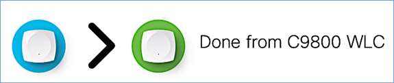
Figure 32. 9800 controller conversion process
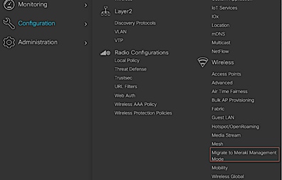
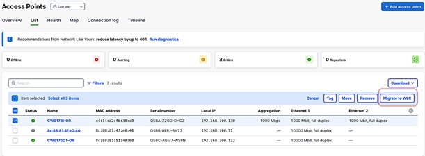
The following are the steps to perform the conversion process.
1. Start the conversion workflow from Configuration > Wireless > Migrate to Meraki Management Mode.
2. Select the APs you want to convert and click Migrate to Meraki Management Mode.
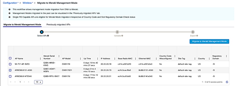
3. The controller will then validate the APs. Select Next.

4. Confirm the change on the selected Access Points.
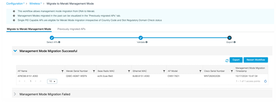
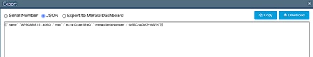
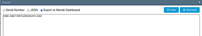
5. Export or download the data to be copied to Meraki Dashboard. The data can be exported in multiple formats – Serial Number, JSON, or Export to Meraki Dashboard.

6. Add devices in Meraki Dashboard. Follow the Meraki Claim process.
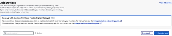
7. Once devices and claimed, the AP will appear in the dashboard in few minutes.
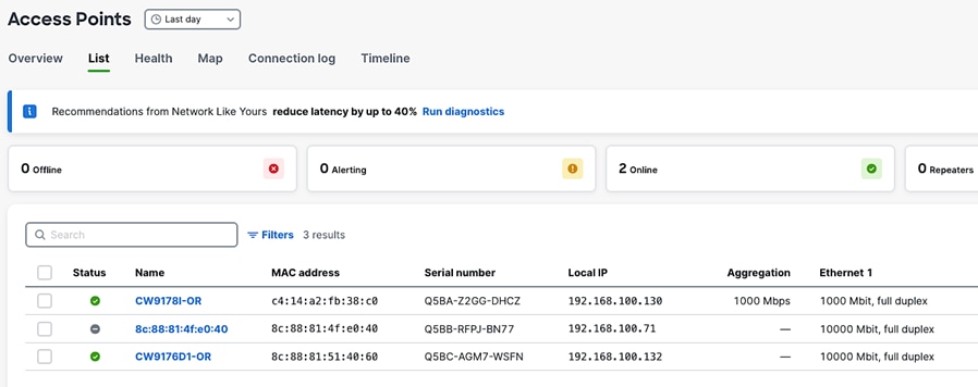
8. To convert an AP from Meraki Management Mode to Catalyst Management Mode, select the AP that you want to migrate to and click on “Migrate to WLC.”
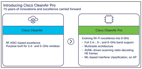
Wi-Fi 6E added 6 GHz spectrum for unlicensed use of Wi-Fi, and with it came new challenges for RF visibility and much more spectrum to monitor. In the past, the Catalyst 9100 APs relied on Cisco CleanAir® (software) and the RF-ASIC (hardware) for features such as packet capture, spectrum analysis, interference detection, and rogue and wireless intrusion prevention system (WIPS) detection. CleanAir and the RF-ASIC were great for RF visibility for the 2.4- and 5-GHz bands; however, with 6 GHz, Cisco CleanAir Pro and the AI/ML-driven scanning radio are being introduced to increase the performance and granularity required to manage this new spectrum (all 1200 MHz of it).
CleanAir Pro is software designed specifically for 6 GHz and the all-new challenges that have come with the introduction of 1200 MHz of spectrum. While many features work in conjunction with the AI/ML-driven scanning radio, CleanAir Pro also works with the Catalyst 9172 series APs’ serving radios. Unlike previous generations of APs, CleanAir Pro can even decode extremely high throughput (EHT, 802.11be) frames, which is crucial since Wi-Fi 7 EHT frames. In the future, there will even be an ML-based interferer classification built directly into the AP software for more efficient interferer analysis, rather than loading the WLC or Cisco Catalyst Center.
Internet of Things integration
IoT Services with Cisco Spaces
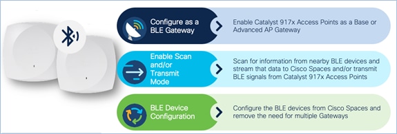
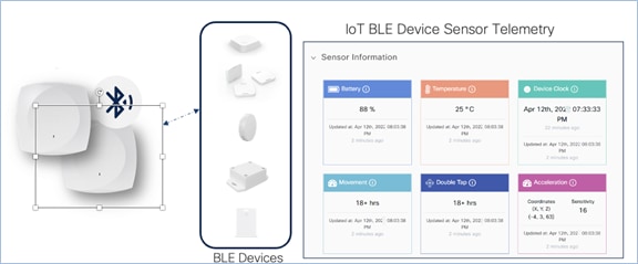
The CW9172 series has a built-in IoT radio that can be used in conjunction with the IoT Services platform service in Cisco Spaces. IoT Services is designed to enable management of Internet of Things (IoT) devices across vendors, form factors, and technology protocols.
Within IoT Services, you can enable a CW9172I & H to be in Scan mode or Transmit mode. In Transmit mode, the AP can broadcast iBeacon, Eddystone URL, and Eddystone UID profiles. While in Scan mode, the AP can scan the vicinity for other BLE devices and receive telemetry data from floor beacons, which can be decoded in Cisco Spaces.
The CW9172 can manage and configure wireless IoT devices if you enable the Advanced AP Gateway feature, which installs a Cisco IOx application on the access point. This saves the user the trouble of having several gateways across different vendors.
The figure below depicts the telemetry data received from a BLE device that is decoded in Cisco Spaces.
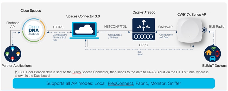
The figure below depicts how BLE data is sent from the Cisco Wireless CW9172I to Cisco Spaces.
The built-in IoT radio requires Cisco Spaces and IoT Services to be configured. Please use the following guides for configuring Cisco Spaces and IoT Services.
● https://www.cisco.com/c/en/us/td/docs/wireless/cisco-dna-spaces/iot-services/b_iot_services.html
● https://www.cisco.com/c/en/us/td/docs/wireless/spaces/config-guide/ciscospaces-configuration-guide.html
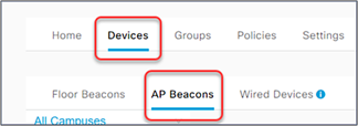
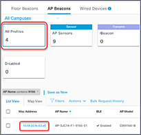
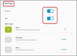
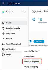
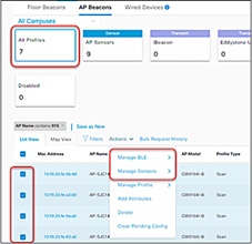
To enable the IoT radio or environmental sensors in Cisco Spaces, go to the specific access point in IoT Services in Cisco Spaces and select the feature to turn on or bulk-enable each feature in the AP Beacons page.
The figures below depict how to enable or disable the IoT radio or environmental sensors on Cisco Spaces through a specific access point.


To learn more about Smart Workspaces or to request a demo, visit https://dnaspaces.cisco.com/smart-workspaces/
The Cisco Wireless 9172I & H supports Site Survey mode. The purpose of this mode is to allow users to conduct wireless site survey testing using a single access point, including understanding RF propagation, client join metrics, and so on, without the need for a controller. This mode converts the AP into a limited standalone mode, enabling it to broadcast 2.4-GHz, 5-GHz, and 6-GHz SSIDs and allowing wireless clients to join via an internal Dynamic Host Configuration Protocol (DHCP) pool. Site Survey mode provides all the control needed to configure and conduct a site survey. It lets users bring the AP into any environment with either a power source or battery backup and conduct a site survey test.
When the CW9172 is in Site Survey mode, you will be able to access the AP’s Web UI for each configuration and view various RF metrics for RF coverage and planning. These configurations include channel number, channel width, Tx power, SSID, and data rates.
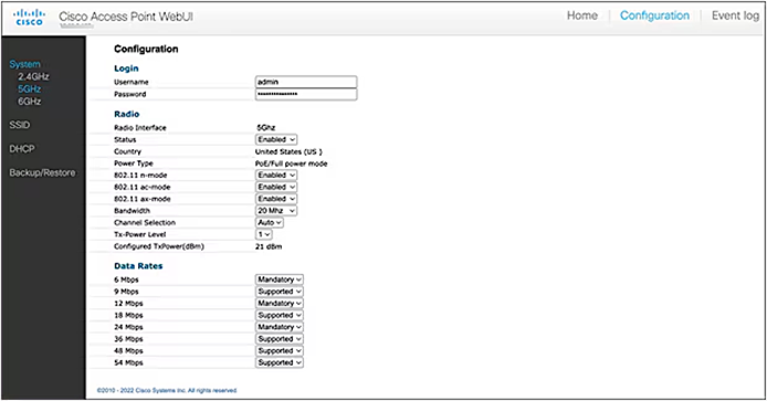
Figure 33. View RF Metrics for AP in Site Survey Mode
The steps below describe how to convert a CW9172 AP into Site Survey mode:
1. Change the AP to Site Survey mode. Enter command “ap site-survey”
2. After booting up, the AP is automatically assigned a static IP of 10.0.23.1.
3. The AP will start broadcasting the C9172_site_survey SSID with open/OWE security.
4. Connect your wireless client with the C9172_site_survey SSID and it will receive an IP from 10.0.23.0/24.
5. Access the AP’s Site Survey Web UI via 10.0.23.1.
6. The first time, the default username and password are admin/admin. You will be directed to reset that insecure password on the first login.
7. When done, convert your AP back to CAPWAP mode to join the controller again. Enter command “ap capwap”
Note:
● If an AP is converted to Site Survey mode while connected to a WLC, it will disjoin and go into standalone mode.
● For the above-mentioned Site Survey functionality, the AP should have joined a Catalyst 9800 WLC at least once. When the AP is in Day 0 mode, the CLI to convert the AP to Site Survey mode is not present.
● The AP carries over the country code configured, while it was connected to the Catalyst 9800 WLC.
References
● Cisco Wireless Global Use Access Points Deployment Guide
● Cisco Wireless 9172I Wi-Fi 7 Access Point Hardware Installation Guide
● Cisco Wireless 9172H Wi-Fi 7 Access Point Hardware Installation Guide
● Detailed Channels and Maximum Power Settings for Cisco Wireless 9172H Access Points, Release 17.17.1