Package contents
Each standard shipment of the Cisco Wireless 9179F Wi-Fi 7 Access Point includes:
-
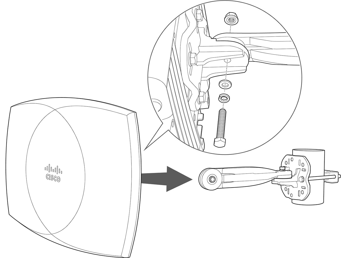
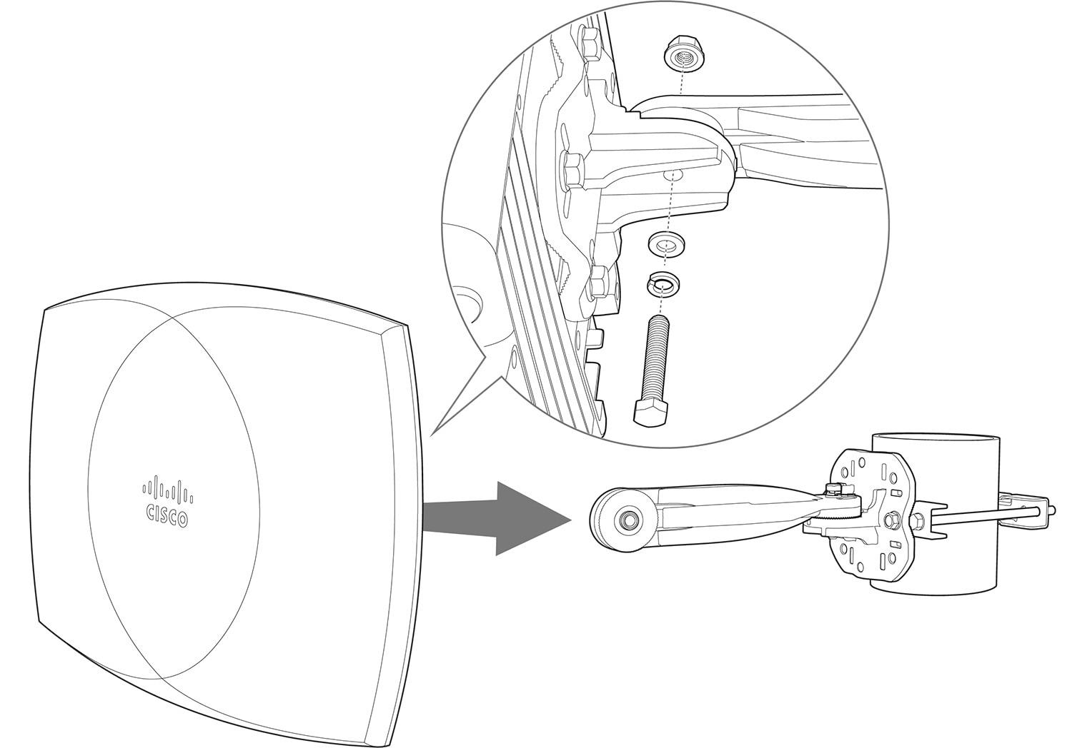
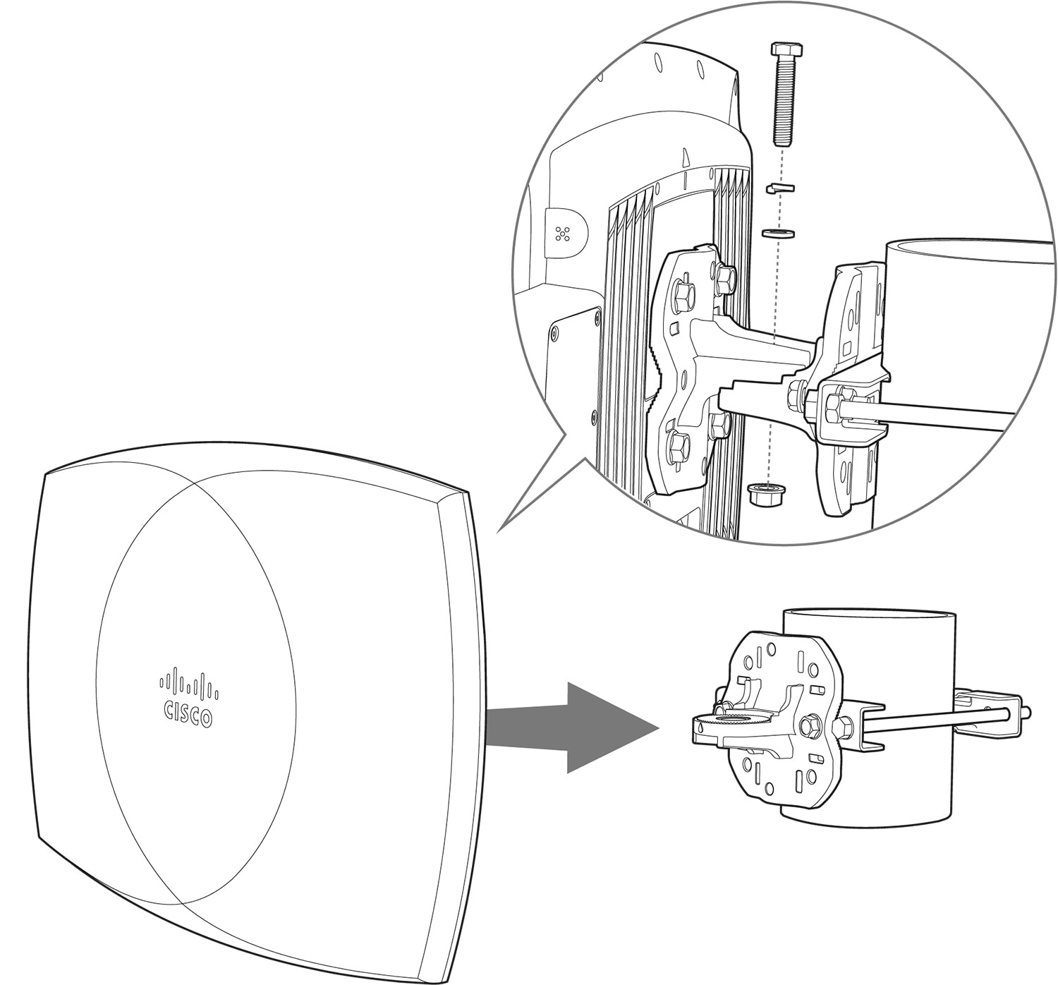
Cisco Wireless 9179F Wi-Fi 7 Access Point (with Indoor Environment Pack (CW-ACC-9179-A-00) pre-installed)
-
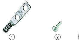
Grounding lug kit with oxide inhibitor
-
CDOC flyer
Separate orderable accessories
These accessories are available as separate orderable items for CW9179F:
|
Accessory |
PID |
|---|---|
|
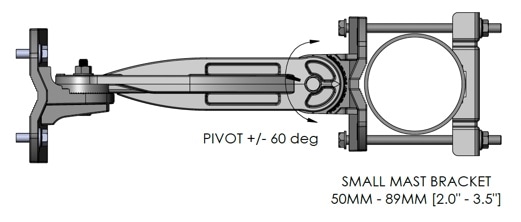
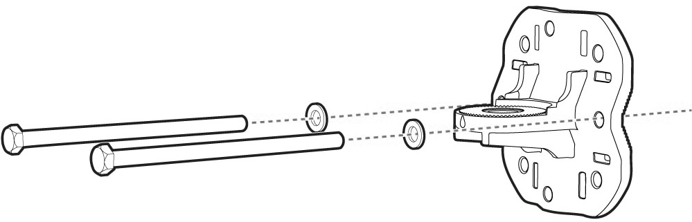
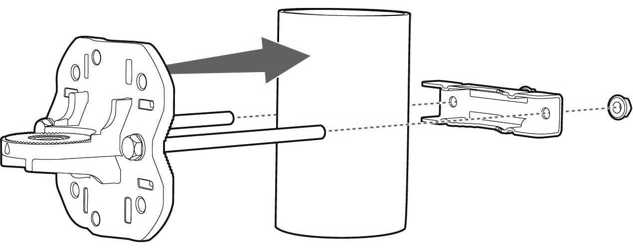
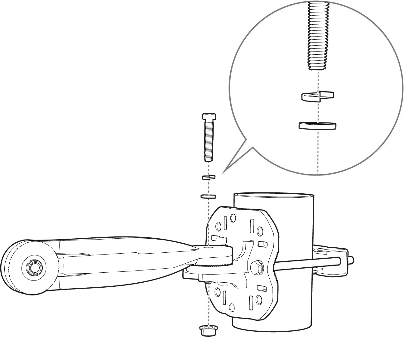
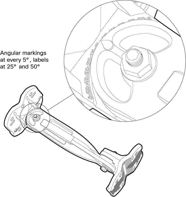
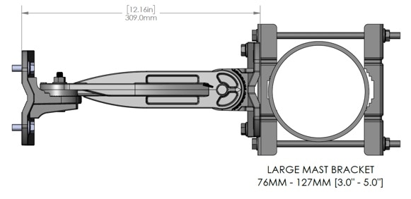
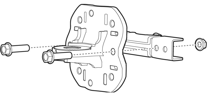
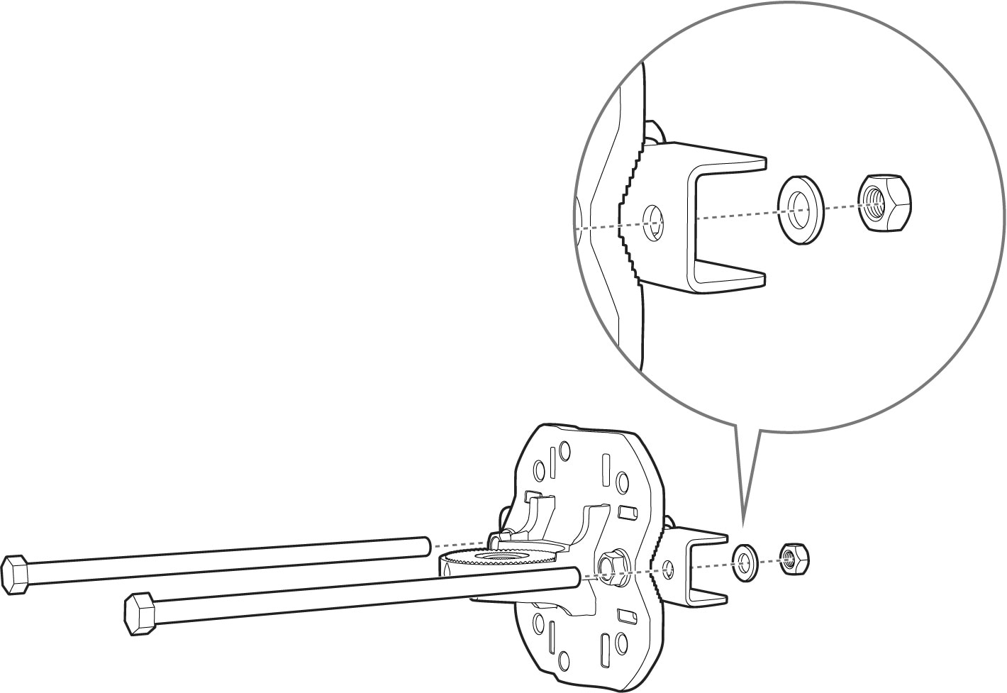
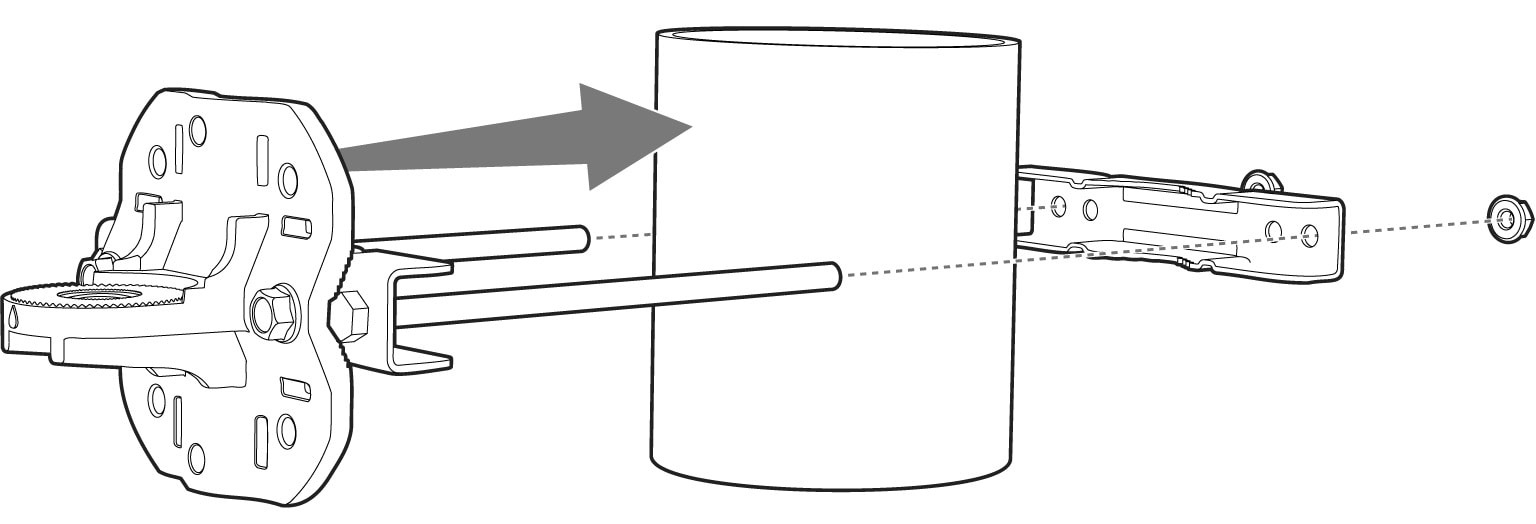
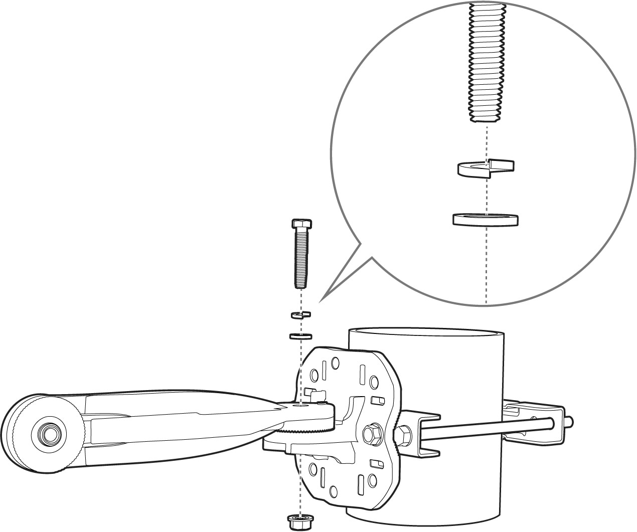
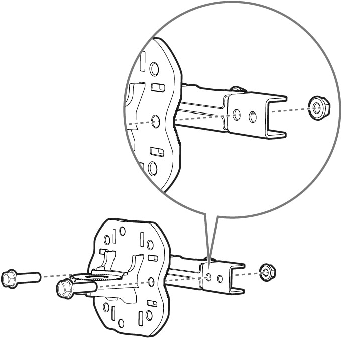
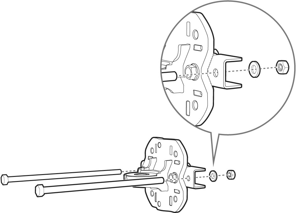
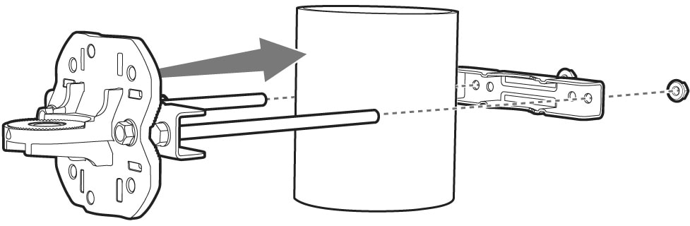
Articulating wall/pole mount bracket |
CW-MNT-ART3 |
|
Outdoor Environment Pack (IP65/ IP67 cover, glands) |
CW-ACC-9179-B-00 |
|
Indoor Environment Pack |
CW-ACC-9179-A-00 |
|
Solar shield kit (required for 45–50°C outdoor) |
CW-ACC-9179-CVR |
|
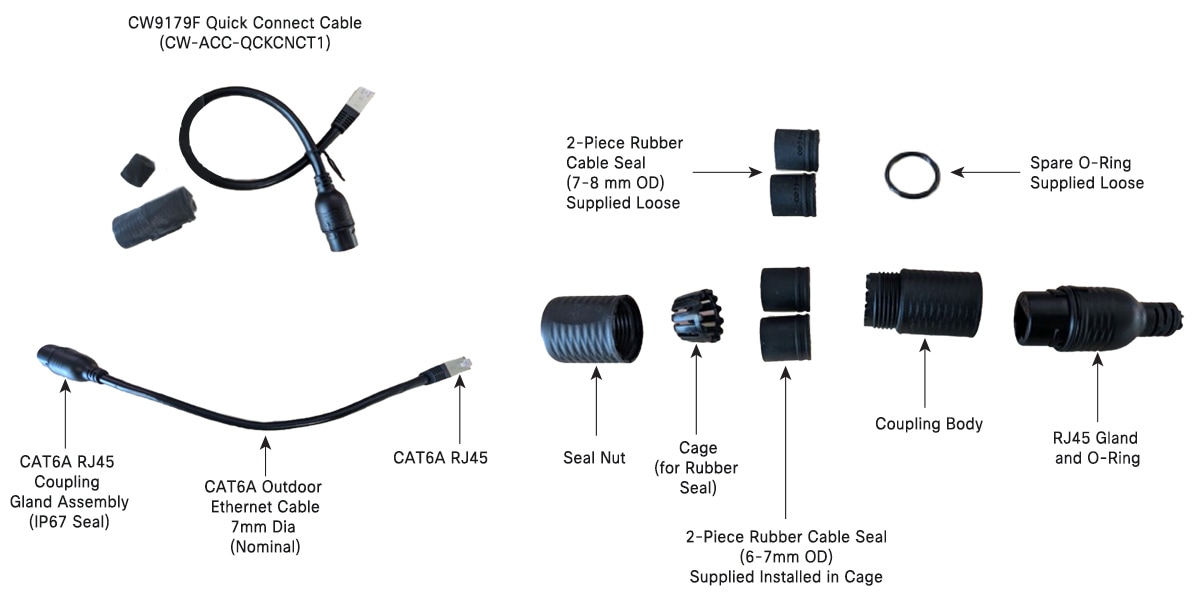
Quick Connect Cable |
CW-ACC-QCKCNCT1 |
|
N-Type to RPTNC adapter connectors (x4) |
CW-ACC-N2RPTNC |


 Feedback