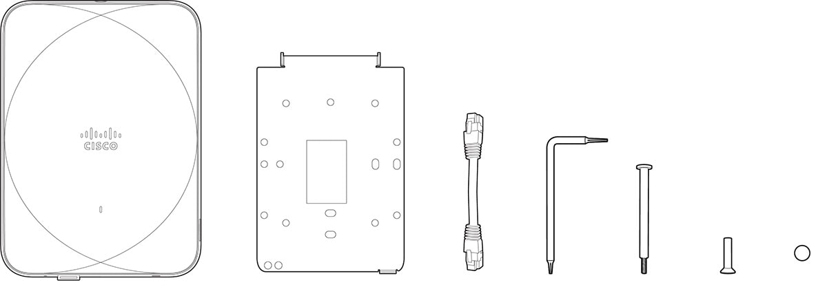
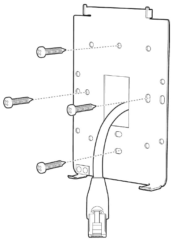
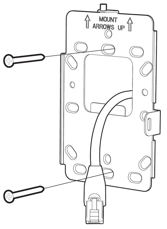
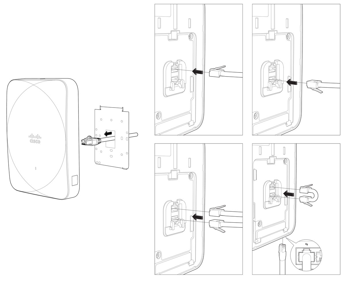
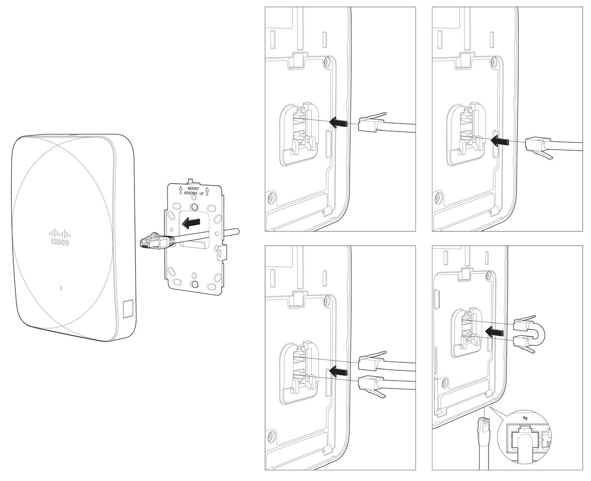
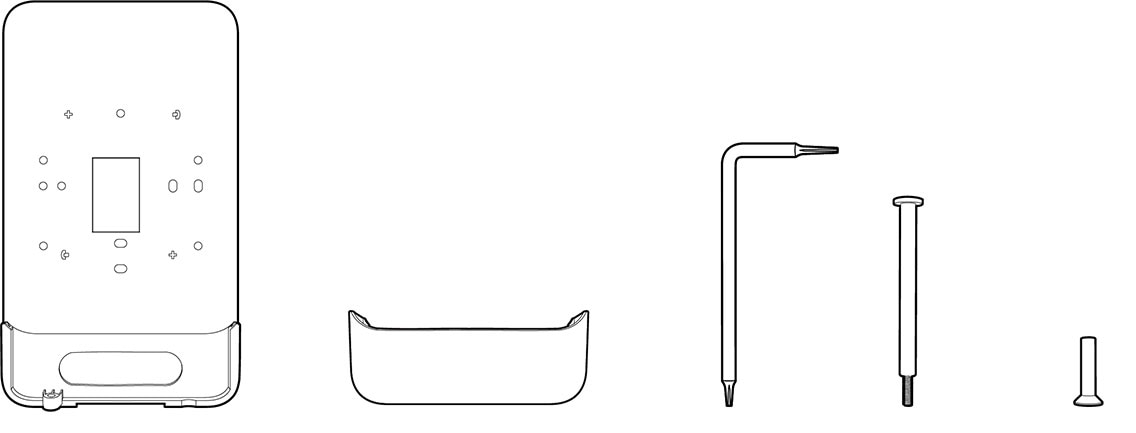
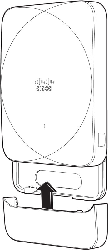
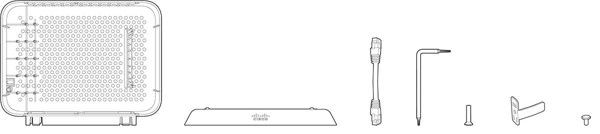
Package contents
Each AP package contains the following items:
-
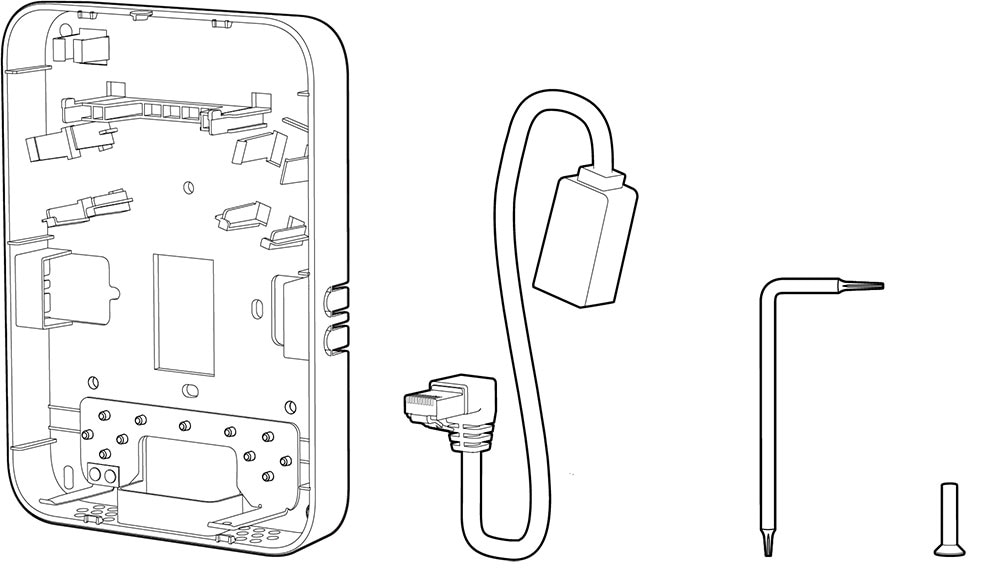
One access point (CW9172H)
-
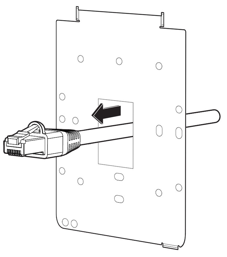
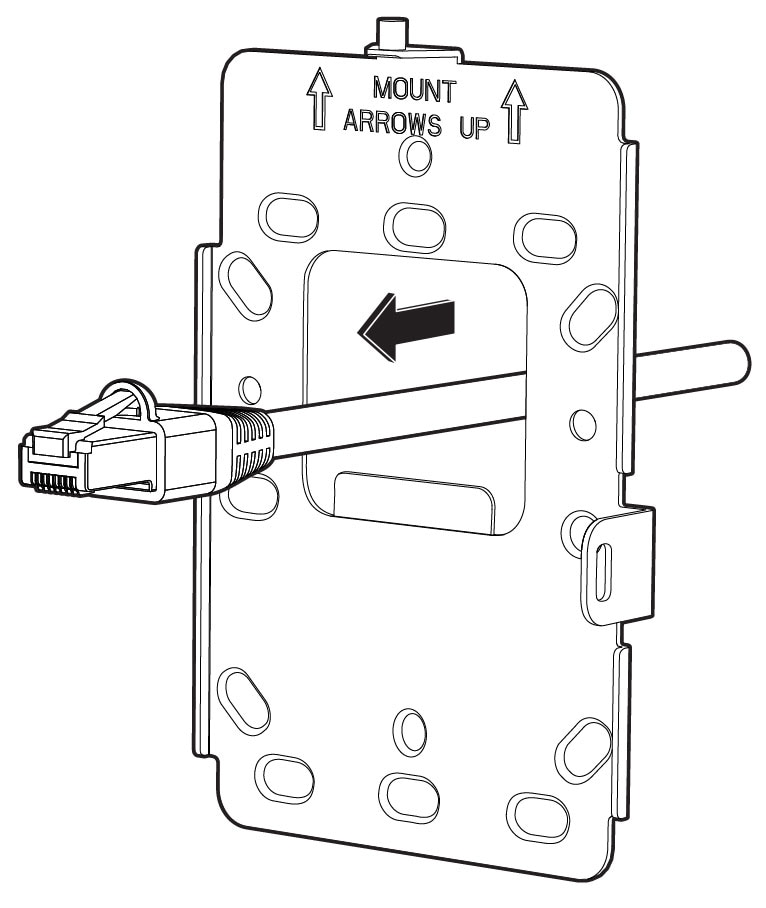
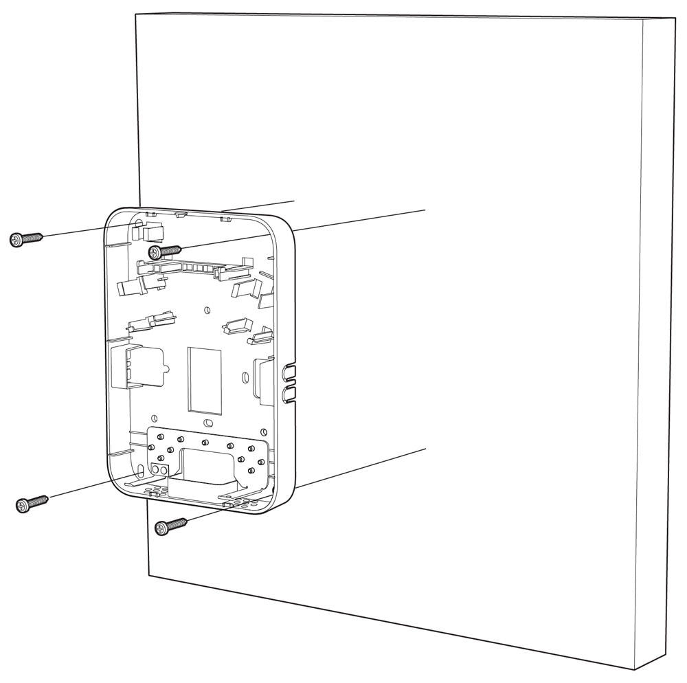
Default mounting bracket: wall plate bracket (CW-MNT-H1)
-
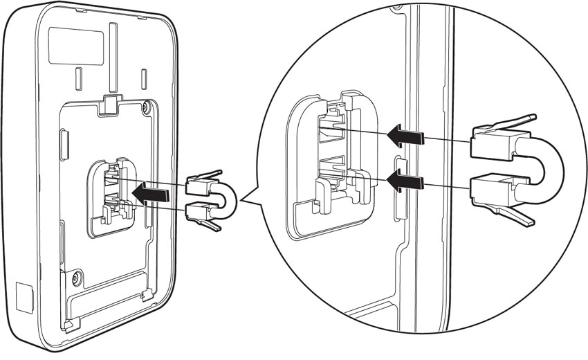
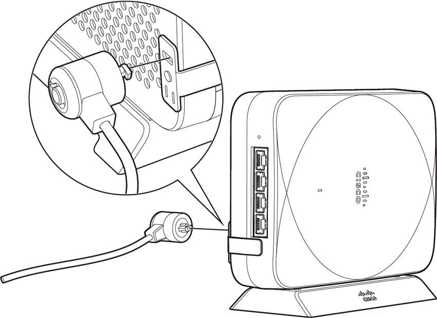
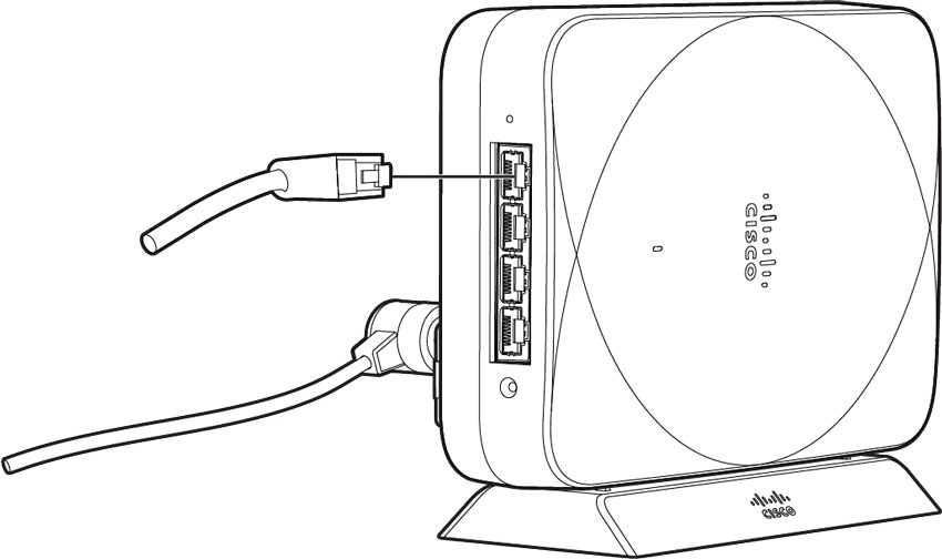
Passthrough cable jumper
-
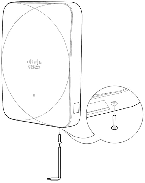
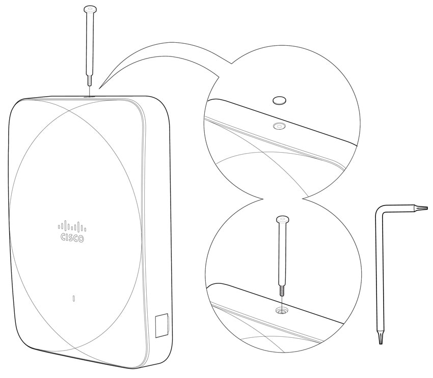
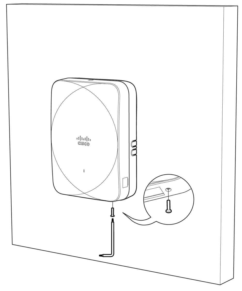
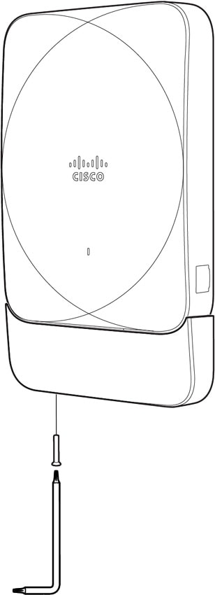
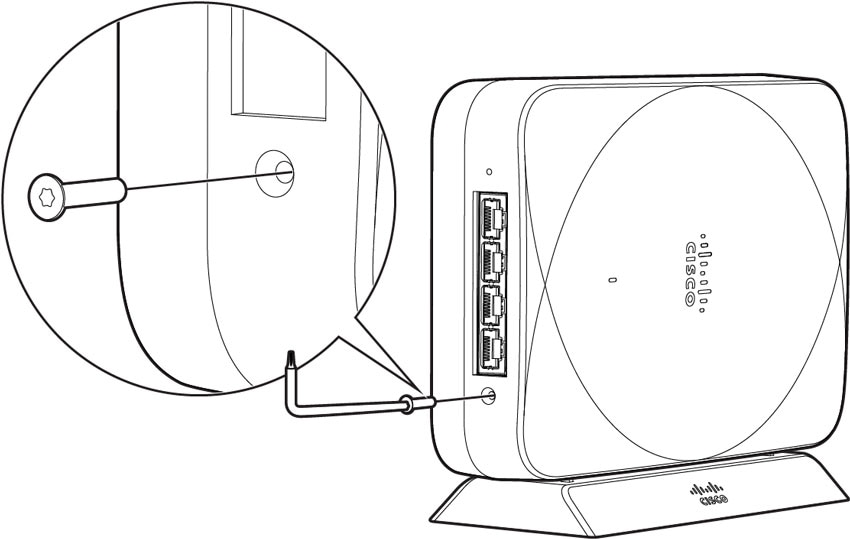
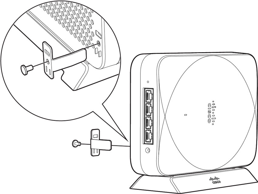
Allen key or security release tool
-
Long Torx (25mm) security screw
-
Two short flat head T8 Torx M2.5x12mm security screws
-
Mylar label to cover the screw
 Note |
The CW9172H is also compatible with MA-MNT-MR-H1A and AIR-AP-BRACKET-W4. |

 Feedback