Troubleshooting
This chapter provides troubleshooting procedures for basic problems with the access point. For the most up-to-date, detailed troubleshooting information, refer to the Cisco Technical Support and Documentation website at the following URL:
Guidelines for Using the Access Point
You should keep these guidelines in mind when you use the access point:
In Layer 3 operation, the access point and the controller can be on the same or different subnets. The access point communicates with the controller using standard IP packets. A Layer 3 access point on a different subnet than the controller requires a DHCP server on the access point subnet and a route to the controller. The route to the controller must have destination UDP ports 12222 and 12223 open for CAPWAP communications. The route to the primary, secondary, and tertiary controllers must allow IP packet fragments.
–![]() Your controllers are connected to switch ports that are configured as trunk ports.
Your controllers are connected to switch ports that are configured as trunk ports.
–![]() Your access points are connected to switch ports that are configured as untagged access ports.
Your access points are connected to switch ports that are configured as untagged access ports.
–![]() A DHCP server is reachable by your access points and has been configured with Option 43. Option 43 provides the IP addresses of the management interfaces of your controllers. Typically, a DHCP server can be configured on a Cisco switch.
A DHCP server is reachable by your access points and has been configured with Option 43. Option 43 provides the IP addresses of the management interfaces of your controllers. Typically, a DHCP server can be configured on a Cisco switch.
–![]() Optionally, a DNS server can be configured to enable CISCO-CAPWAP-CONTROLLER. Use local domain to resolve to the IP address of the management interface of your controller.
Optionally, a DNS server can be configured to enable CISCO-CAPWAP-CONTROLLER. Use local domain to resolve to the IP address of the management interface of your controller.
–![]() Your controllers are configured and reachable by the access points.
Your controllers are configured and reachable by the access points.
–![]() Your controllers are configured with the access point MAC addresses and the MAC filter list is enabled.
Your controllers are configured with the access point MAC addresses and the MAC filter list is enabled.
–![]() Your switch must forward DHCP requests.
Your switch must forward DHCP requests.
- After the access points are associated to the controller, you should change the bridge group name (BGN) from the default value. With the default BGN, the mesh access points (MAPs) can potentially try to connect with other mesh networks and slow down the convergence of the network.
Convergence Delays
During deployment, the access points can experience convergence delays due to various causes. The following list identifies some operating conditions that can cause convergence delays:
- A root access point (RAP) attempts to connect to a controller using any of the wired ports (cable, fiber-optic, PoE-in). If the wired ports are operational, the RAP can potentially spend several minutes on each port prior to connecting to a controller.
- If a RAP is unable to connect to a controller over the wired ports, it attempts to connect using the wireless network. This results in additional delays when multiple potential wireless paths are available.
- If a MAP is unable to connect to a RAP using a wireless connection, it then attempts to connect using any available wired port. The access point can potentially spend several minutes for each connection method, before attempting the wireless network again.
Bridge Loop
The access point supports packet bridging between wired and wireless network connections. The same network must never be connected to multiple wired ports on an access point or on two bridged access points. A bridge loop causes network routing problems.
Controller DHCP Server
The controller DHCP server only assigns IP addresses to lightweight access points and wireless clients associated to an access point. It does not assign an IP address to other devices, including Ethernet bridging clients on the mesh access points.
MAP Data Traffic
If the signal on the access point backhaul channel has a high signal-to-noise ratio, it is possible for a MAP to connect to the controller, via parent node, but not be able to pass data traffic, such as pinging the access point. This can occur because the default data rate for backhaul control packets is set to 6 Mb/s, and the backhaul data rate set to auto by the user.
Controller MAC Filter List
Before activating your access point, you must ensure that the access point MAC address has been added to the controller MAC filter list and that Mac Filter List is enabled.

Note![]() The access point MAC address and barcode is located on the bottom of the unit. When two MAC addresses are shown, use the top MAC address.
The access point MAC address and barcode is located on the bottom of the unit. When two MAC addresses are shown, use the top MAC address.
To view the MAC addresses added to the controller MAC filter list, you can use the controller CLI or the controller GUI:
- Controller CLI—Use the show macfilter summary controller CLI command to view the MAC addresses added to the controller filter list.
- Controller GUI—Log into your controller web interface using a web browser, and choose SECURITY > AAA > MAC Filtering to view the MAC addresses added to the controller filter list.
Using DHCP Option 43
You can use DHCP Option 43 to provide a list of controller IP addresses to the access points, enabling the access point to find and join a controller. Refer to the product documentation for your DHCP server for instructions on configuring DHCP Option 43. To see sample configurations for DHCP Option 43 for, go to the following URL:
http://www.cisco.com/c/en/us/support/docs/wireless-mobility/wireless-lan-wlan/97066-dhcp-option-43-00.html
Accessing the Console Port and the Reset Button
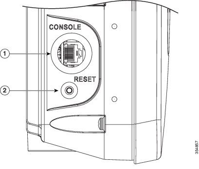
The access point has a console port and a reset button located on the right side (see Figure 3-1). The console port is located under a covering plug. The reset button is located under a screw.
Figure 3-1 Console Port and Reset Button Location
|
|
Use a large Phillips or Flat Blade screw driver to remove the covering plug of the port. Do not discard plug and rubber seal unless you are certain that the port will not have to be re-plugged. Inspect the seal of the plug and properly tighten it every time the plug is removed and replaced. Tighten the plug to 15 lbf-in. |
|
The reset button is recessed in a small hole that is sealed with a screw and a rubber gasket. For information on how to use the reset button, see the “Resetting the Access Point” section. |
Resetting the Access Point
Using the Reset button you can:
- Reset the AP to the default factory-shipped configuration.
- Clear the AP internal storage, including all configuration files.
Step 1![]() Use a Phillips screwdriver to remove the reset button screw.
Use a Phillips screwdriver to remove the reset button screw.
Ensure that your do not to lose the screw and the rubber gasket.
Step 2![]() To press the Reset button, use a straightened paper-clip or a small screwdriver or a pen. See the section following this procedure for information on using the Reset button.
To press the Reset button, use a straightened paper-clip or a small screwdriver or a pen. See the section following this procedure for information on using the Reset button.
Strictly follow this procedure after you have finished using the Reset button.
Step 3![]() Inspect the gasket. If the gasket has any signs of damage, it should be replaced to avoid water leakage into the unit.
Inspect the gasket. If the gasket has any signs of damage, it should be replaced to avoid water leakage into the unit.
Step 4![]() Close the recess with the screw and the gasket. Use a Phillips screwdriver to tighten the screw to 1.8 to 2 lb.ft (2.49 to 2.71 Nm).
Close the recess with the screw and the gasket. Use a Phillips screwdriver to tighten the screw to 1.8 to 2 lb.ft (2.49 to 2.71 Nm).
To use the Reset button, press, and keep pressed, the Reset button on the access point during the AP boot cycle. Wait until the AP status LED changes to Amber. During this, the AP console shows a seconds counter, counting the number of seconds the Reset button is pressed. Then:
- To reset the AP to it’s default factory-shipped configuration, keep the Reset button pressed for less than 20 seconds. The AP configuration files are cleared.
This resets all configuration settings to factory defaults, including passwords, WEP keys, the IP address, and the SSID.
- To clear the AP internal storage, including all configuration files, keep the Reset button pressed for more than 20 seconds, but less than 60 seconds.
The AP status LED changes from Amber to Red, and all the files in the AP storage directory are cleared.
If you keep the Reset button pressed for more than 60 seconds, the Reset button is assumed faulty and no changes are made.
Monitoring the Access Point Status LED
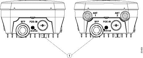
If your access point is not working properly, look at the LED on the bottom of the unit. You can use them to quickly assess the status of the unit. Figure 3-2 shows the location of the access point LED.
Figure 3-2 Access Point Status LED
|
|
If your access point is not working properly, look at the status LED on the bottom of the unit, to quickly assess the status of the unit. The access point LED signals are listed in Table 3-1 . |
||
Note![]() It is expected that there will be small variations in LED color intensity and hue from unit to unit. This is within the normal range of the LED manufacturer specifications and is not a defect.
It is expected that there will be small variations in LED color intensity and hue from unit to unit. This is within the normal range of the LED manufacturer specifications and is not a defect.
The access point LED signals are listed in Table 3-1 .
Verifying Controller Association
To verify that your access point is associated to the controller, follow these steps:
Step 1![]() Log into your controller web interface using a web browser.
Log into your controller web interface using a web browser.
You can also use the controller CLI show ap summary command from the controller console port.
Step 2![]() Click Wireless, and verify that your access point MAC address is listed under Ethernet MAC.
Click Wireless, and verify that your access point MAC address is listed under Ethernet MAC.
Step 3![]() Log out of the controller, and close your web browser.
Log out of the controller, and close your web browser.
Changing the Bridge Group Name
The bridge group name (BGN) controls the association of the access points to a RAP. BGNs can be used to logically group the radios to avoid different networks on the same channel from communicating with each other. This setting is also useful if you have more than one RAP in your network in the same area.
If you have two RAPs in your network in the same area (for more capacity), we recommend that you configure the two RAPs with different BGNs and on different channels.
The BGN is a string of ten characters maximum. A factory-set bridge group name (NULL VALUE) is assigned during manufacturing. It is not visible to you, but allows new access point radios to join a network of new access points. The BGN can be reconfigured from the Controller CLI and GUI. After configuring the BGN, the access point reboots.
After the access points are deployed and associated to the controller, the BGN should be changed from the default value to prevent the MAPs from attempting to associate to other mesh networks.
The BGN should be configured very carefully on a live network. You should always start with the most distant access point (last node) from the RAP and move towards the RAP. If you start configuring the BGN in a different location, then the access points beyond this point (farther away) are dropped, as they have a different BGN.
To configure the BGN for the access points using the controller GUI, follow these steps:
Step 1![]() Log into your controller using a web browser.
Log into your controller using a web browser.
Step 2![]() Click Wireless. When access points associates to the controller, the access point name appears in the AP Name list.
Click Wireless. When access points associates to the controller, the access point name appears in the AP Name list.
Step 3![]() Click on an access point name.
Click on an access point name.
Step 4![]() Find the Mesh Information section, and enter the new BGN in the Bridge Group Name field.
Find the Mesh Information section, and enter the new BGN in the Bridge Group Name field.
Step 6![]() Repeat Steps 2 through 5 for each access point.
Repeat Steps 2 through 5 for each access point.
Step 7![]() Log out from your controller, and close your web browser.
Log out from your controller, and close your web browser.
 Feedback