- Unpacking the Access Point
- Mounting the Access Point
- Choosing a Mounting Kit
- Wall Mounting the Access Point with AIR-ACC1530-PMK1=
- Wall Mounting the Access Point with AIR-ACC1560-PMK1=
- Pole Mounting the Access Point with AIR-ACC1530-PMK1=
- Pole Mounting the Access Point with the AIR-ACC1560-PMK1= Kit
- Wall Mounting the AP using AIR-ACC1530-PMK2= Pivoting Mounting Kit
- Pole Mounting the AP using AIR-ACC1530-PMK2= Pivoting Mounting Kit
- Horizontally Mounting the Access Point using AIR-ACC1530-PMK2=
- Installing AP Cover AIR-ACC1560-CVR=
- Installing External Antennas
- Installing a Lightning Arrestor
Installing the Access Point
This chapter describes how to install the 1560 access point and its accessories. It contains the following sections:
Unpacking the Access Point
To unpack the access point, follow these steps:
Step 1![]() Open the shipping container and carefully remove the contents.
Open the shipping container and carefully remove the contents.
Step 2![]() Return all packing materials to the shipping container, and save it.
Return all packing materials to the shipping container, and save it.
Step 3![]() Ensure that all items listed in “Package Contents” are included in the shipment. If any item is damaged or missing, notify your authorized Cisco sales representative.
Ensure that all items listed in “Package Contents” are included in the shipment. If any item is damaged or missing, notify your authorized Cisco sales representative.
Your shipment may also contain additional equipment as per your order, as listed in Optional Tools and Hardware From Cisco.
For additional hardware that is required for installation, see Additional Tools and Hardware Required for Installation.
Package Contents
Optional Tools and Hardware From Cisco
Depending on what you ordered, the following optional equipment may be part of your shipment:
- External antennas. See the “Installing External Antennas” section.
- Wall/Pole mount bracket AIR-ACC1530-PMK1=
- Wall/Pole mount bracket for AP and AC/DC power adapter AIR-ACC1560-PMK1=
- Wall/Pole mount bracket with tilt mechanism, spare only AIR-ACC1530-PMK2=
- Street light power tap (AIR-PWR-ST-LT-R3P=), works only with the AC/DC power adapter.
- Power injector AIR-PWRINJ6=
- AP cover / Solar Shield for 1560, AIR-ACC1560-CVR=. Spare only.
- AC/DC power adapter, AIR-PWRADPT-RGD1=. Spare only.
- AIR-PWRINJ-60-PMK= mounting bracket for AIR-PWRINJ-60RGDx=
- Spare Parts kit containing extra cable glands, power connector, ground lug, etc. (AIR-ACC1530-KIT1=)
- AIR-PWRINJ-60RGD1=
- AIR-PWRINJ-60RGD2=
- FIPS kit (AIRLAP-FIPSKIT=)
- Lightning Arrestor kit (AIR-ACC245LA-N=)
Additional Tools and Hardware Required for Installation
You need to independently procure the following tools and materials which maybe required during various stages of installing the AP:
- Ground lug crimping tool (Panduit CT-720 with CD-720-1 die)
- 6-AWG copper ground wire
- 10 mm open end or box wrench
- 13 mm box-end wrench or socket set
- 16 mm box-end wrench or socket set
- Large flat or Phillips screw driver (for port plugs)
- Small flat screwdriver for DC power connector
- Shielded outdoor-rated Ethernet (CAT5e or better) cable of 0.20 to 0.35 inches (0.51 to 0.89 cm) diameter.
- Ethernet RJ-45 connector and installation tool
- Shielded outdoor-rated DC power cable with 0.20 to 0.35 inch (.0.51 to 0.89 cm) diameter
- Ground rod, as required by local regulations
Pre-Installation Checks and Installation Guidelines
As the access point is a radio device, it is susceptible to common causes of interference that can reduce throughput and range. Follow these basic guidelines to ensure the best possible performance:
- Thoroughly review the information provided in Safety Guidelines and Warnings.
- For information on planning and initially configuring your Cisco Mesh network, refer to the Cisco Wireless Access Points, Design and Deployment Guide, Release 7.3.
- Review the FCC guidelines for installing and operating outdoor wireless LAN devices at:
http://www.cisco.com/c/en/us/products/collateral/routers/3200-series-rugged-integrated-services-routers-isr/data_sheet_c78-647116.html
- Install the access point in an area where structures, trees, or hills do not obstruct radio signals to and from the access point.
- We recommend installing the access points no higher than 40 feet to allow support for wireless clients on the ground. Best throughput is achieved when all the access points are mounted at the same height.
- The console port is under a sealed plug. Inspect the seal of the plug at the time of installation. Every time the plug is removed or replaced, properly tighten it. Tighten the plug to 15 lbf-in. If you do not tighten the plug properly, it will not meet IP67 criteria, and may lead to water leaking into the unit.
- If the DC power port, SFP port, or the PoE-In port is not in use, then the port’s covering plug must be tightened to 12.5 lbf-in torque. Otherwise, it may lead to water leaking into the access point.

Note![]() To calculate path loss and to determine how far apart to install access points, consult an RF planning expert.
To calculate path loss and to determine how far apart to install access points, consult an RF planning expert.
Before you begin the installation process, ensure the following:
- Perform a site survey. See the “Performing Site Surveys” section.
- Your network infrastructure devices must be operational and properly configured.
- Your controllers are connected to switch trunk ports.
- Your switch is configured with untagged access ports for connecting your access points.
- A DHCP server with Option 43 configured is reachable by your access points, or manually configure the controller information in the access point. For information on configuring the DHCP Option 43, visit the following URL:
http://www.cisco.com/c/en/us/support/docs/wireless-mobility/wireless-lan-wlan/97066-dhcp-option-43-00.html
- Become familiar with the access point installation components. See the “Typical Access Point Installation Components” section.
Typical Access Point Installation Components
The access point is designed to be installed in an outdoor environment, such as the exterior roof overhang of a tall building or a streetlight pole. Carefully review Figure 2-1 to become familiar with the system components, connectors, indicators, cables, system interconnection, and grounding.
Figure 2-1 Components in a Typical Access Point Installation
|
|
|
||
|
|
Shielded outdoor-rated Ethernet |
|
|
|
|
|
||
|
|
|
||
|
|
|
|
|
Mounting the Access Point
This section provides instructions for installing your access points. Personnel installing the access point must have a good understanding of wireless access points, bridging techniques, and grounding methods.
Choosing a Mounting Kit
The 1560 Series Access Point can be wall, pole, or tower mounted. The available mounting kits are provided in the table below.
Note ●![]() When mounting an access point vertically, ensure that the access point is oriented with the LED indicators pointing down.
When mounting an access point vertically, ensure that the access point is oriented with the LED indicators pointing down.
- You must also ensure the access point is mounted in such a way as to ensure that all antenna ports and the console port are accessible for future use.
- Omnidirectional antennas need to be mounted vertically.
- Directional antennas need to be installed with the main beam aimed parallel to or tilted down toward the horizon.
Wall Mounting the Access Point with AIR-ACC1530-PMK1=
The AIR-ACC1530-PMK1= mounting kit contains a mounting bracket for wall mounting or pole mounting.
You can use the mounting bracket as a template to mark the positions of the mounting holes for your installation, install the mounting bracket, and then attach the access point to the bracket.
Table 2-1 lists the materials needed for this installation.
|
|
|
|---|---|
Crimping tool for ground lug, Panduit CT-720 with CD-720-1 die (http://www.panduit.com) |
|

To mount the access point vertically on a wall, follow these instructions:
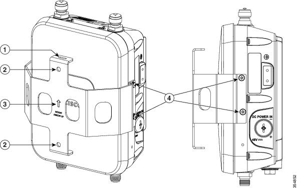
Step 1![]() Use the mounting bracket as a template to mark four screw hole locations on the mounting wall. The mounting bracket screw hole locations are shown in Figure 2-2. The dimensions of the mounting bracket is shown in Figure 2-3.
Use the mounting bracket as a template to mark four screw hole locations on the mounting wall. The mounting bracket screw hole locations are shown in Figure 2-2. The dimensions of the mounting bracket is shown in Figure 2-3.
Step 2![]() Use four screws and, if required, wall anchors to attach the mounting plate to the mounting surface. These screws and anchors are to be sourced independently.
Use four screws and, if required, wall anchors to attach the mounting plate to the mounting surface. These screws and anchors are to be sourced independently.
Note![]() You can use an exterior-grade plywood backboard to mount the access point to stucco, cement, or drywall.
You can use an exterior-grade plywood backboard to mount the access point to stucco, cement, or drywall.
Note![]() The mounting wall, attaching screws, and wall anchors must be able to support a 50-lb (22.7 kg) static weight.
The mounting wall, attaching screws, and wall anchors must be able to support a 50-lb (22.7 kg) static weight.
Step 3![]() Screw an M6 x12 mm bolt into each of the four support bolt holes on the back of the access point. Do not screw the bolt all the way in, but leave a gap of approximately 0.13 inch (3.3 mm).
Screw an M6 x12 mm bolt into each of the four support bolt holes on the back of the access point. Do not screw the bolt all the way in, but leave a gap of approximately 0.13 inch (3.3 mm).
Step 4![]() Position the access point against mounting bracket such that the four support bolts on the back of the AP, slot into the keyhole slots on the mounting bracket.
Position the access point against mounting bracket such that the four support bolts on the back of the AP, slot into the keyhole slots on the mounting bracket.
Step 5![]() Slide the access point down to sit securely in keyhole slots on the mounting bracket.
Slide the access point down to sit securely in keyhole slots on the mounting bracket.
Note![]() The access point should be mounted with the status LED on the base facing downwards.
The access point should be mounted with the status LED on the base facing downwards.
Step 6![]() Using a 10mm wrench, tighten the four bolts that connect the access point to the bracket, to a torque of 40 lbf-in.
Using a 10mm wrench, tighten the four bolts that connect the access point to the bracket, to a torque of 40 lbf-in.
Step 7![]() Proceed with installing antennas (only for external antenna models), connecting the data cables, grounding the access point, powering and configuring the access point.
Proceed with installing antennas (only for external antenna models), connecting the data cables, grounding the access point, powering and configuring the access point.
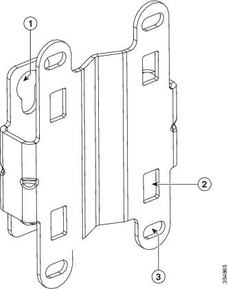
Figure 2-2 Mounting Bracket for Wall and Pole Mounting
|
|
|
Bracket mount holes for fastening bracket to the wall. You can use bolts of up to 1/4" or 6 mm in diameter. |
|
|
|
One of four slots for steel band clamps, used for pole mounting only. |
|
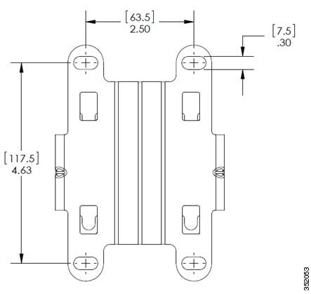
Figure 2-3 Mounting Bracket Dimensions
Wall Mounting the Access Point with AIR-ACC1560-PMK1=
The AIR-ACC1560-PMK1= mounting kit contains a mounting bracket, for wall mounting or pole mounting, the access point and the power supply together.
You can use the mounting bracket as a template to mark the positions of the mounting holes for your installation, install the mounting bracket, and then attach the access point to the bracket.
Table 2-1 lists the materials needed for this installation.
|
|
|
|---|---|
Crimping tool for ground lug, Panduit CT-720 with CD-720-1 die (http://www.panduit.com) |
|
To mount the access point vertically on a wall, follow these instructions:
Step 1![]() Use the mounting bracket as a template to mark six screw hole locations on the mounting wall. The mounting bracket screw hole locations and the dimensions of the mounting bracket are shown in Figure 2-4.
Use the mounting bracket as a template to mark six screw hole locations on the mounting wall. The mounting bracket screw hole locations and the dimensions of the mounting bracket are shown in Figure 2-4.
Step 2![]() Use six screws and, if required, wall anchors to attach the mounting plate to the mounting surface. These screws and anchors are to be sourced independently.
Use six screws and, if required, wall anchors to attach the mounting plate to the mounting surface. These screws and anchors are to be sourced independently.
Note![]() You can use an exterior-grade plywood backboard to mount the access point to stucco, cement, or drywall.
You can use an exterior-grade plywood backboard to mount the access point to stucco, cement, or drywall.
Note![]() The mounting wall, attaching screws, and wall anchors must be able to support a 50-lb (22.7 kg) static weight.
The mounting wall, attaching screws, and wall anchors must be able to support a 50-lb (22.7 kg) static weight.
Step 3![]() Screw an M6 x12 mm bolt into each of the four support bolt holes on the back of the access point. Do not screw the bolt all the way in, but leave a gap of approximately 0.13 inch (3.3 mm).
Screw an M6 x12 mm bolt into each of the four support bolt holes on the back of the access point. Do not screw the bolt all the way in, but leave a gap of approximately 0.13 inch (3.3 mm).
Step 4![]() Position the access point against mounting bracket such that the four support bolts on the back of the AP, slot into the keyhole slots on the mounting bracket.
Position the access point against mounting bracket such that the four support bolts on the back of the AP, slot into the keyhole slots on the mounting bracket.
Step 5![]() Slide the access point down to sit securely in keyhole slots on the mounting bracket.
Slide the access point down to sit securely in keyhole slots on the mounting bracket.
Note![]() The access point should be mounted with the status LED on the base facing downwards.
The access point should be mounted with the status LED on the base facing downwards.
Step 6![]() Using a 10mm wrench, tighten the four bolts that connect the access point to the bracket, to a torque of 40 lbf-in.
Using a 10mm wrench, tighten the four bolts that connect the access point to the bracket, to a torque of 40 lbf-in.
Step 7![]() Proceed with installing antennas (only for external antenna models), connecting the data cables, grounding the access point, powering and configuring the access point..
Proceed with installing antennas (only for external antenna models), connecting the data cables, grounding the access point, powering and configuring the access point..
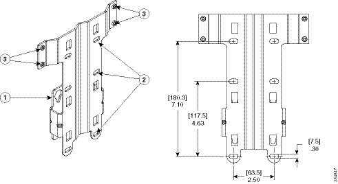
Figure 2-4 Mounting Bracket for Wall and Pole Mounting AP with Power Supply
|
|
|
||
|
|
Three of six bracket mount holes for fastening the bracket to a wall. Support bolts of up to 1/4" (6 mm) in diameter. |
|
Pole Mounting the Access Point with AIR-ACC1530-PMK1=
The AIR-ACC1530-PMK1= mounting kit contains a mounting bracket that can be used for both wall mounting and pole mounting. This kit can be used to install the access point on a pole, mast or streetlight. It supports metal, wood or fiberglass poles from 2 to 8 inches in diameter.
Table 2-3 Materials Needed to Mount the AP on a Vertical Pole
To mount the access point onto a vertical pole, follow these steps:
Step 1![]() Select a mounting location on the pole to mount the access point. You can attach the access point to a pole having a diameter of 2 to 8 inches (5.1 to 20.1 cm).
Select a mounting location on the pole to mount the access point. You can attach the access point to a pole having a diameter of 2 to 8 inches (5.1 to 20.1 cm).
Note![]() If you will be using a streetlight power tap adapter, position the access point within 3 ft (1 m) of the outdoor light control. An AC/DC adapter needs to be used for street light pole deployments.
If you will be using a streetlight power tap adapter, position the access point within 3 ft (1 m) of the outdoor light control. An AC/DC adapter needs to be used for street light pole deployments.
Step 2![]() Hold the bracket up against the pole, and slide the two band straps through the top and bottom sets of mounting slots on the mounting bracket (see Figure 2-5).
Hold the bracket up against the pole, and slide the two band straps through the top and bottom sets of mounting slots on the mounting bracket (see Figure 2-5).
Step 3![]() Wrap the band straps around the pole, lock them and then lightly tighten the clamps using a wrench. Only tighten them enough to keep the bracket from sliding down the pole
Wrap the band straps around the pole, lock them and then lightly tighten the clamps using a wrench. Only tighten them enough to keep the bracket from sliding down the pole
Step 4![]() Screw an M6 bolt into each of the four bolt holes on the back side of the access point. Do not screw the bolt in all the way. Leave a gap of about 0.13" (3.3mm).
Screw an M6 bolt into each of the four bolt holes on the back side of the access point. Do not screw the bolt in all the way. Leave a gap of about 0.13" (3.3mm).
Step 5![]() Position the four bolts on the access point into the bracket keyhole slots. Check to be sure that the access point is properly seated in the slots (see Figure 2-5).
Position the four bolts on the access point into the bracket keyhole slots. Check to be sure that the access point is properly seated in the slots (see Figure 2-5).
Note![]() The access point should be mounted with the status LED on the base facing downwards.
The access point should be mounted with the status LED on the base facing downwards.
Step 6![]() Using a 10mm wrench, tighten the four bolts that connect the access point to the bracket to a torque of 40 lbf-in.
Using a 10mm wrench, tighten the four bolts that connect the access point to the bracket to a torque of 40 lbf-in.
Step 7![]() Locate the access point to its final position. Tighten the band clamps with the wrench so that the access point does not slide on the pole. Ensure that the clamps are tight enough to not let the AP move.
Locate the access point to its final position. Tighten the band clamps with the wrench so that the access point does not slide on the pole. Ensure that the clamps are tight enough to not let the AP move.
Step 8![]() Proceed with installing antennas (only for external antenna models), connecting the data cables, grounding the access point, powering and configuring the access point.
Proceed with installing antennas (only for external antenna models), connecting the data cables, grounding the access point, powering and configuring the access point.
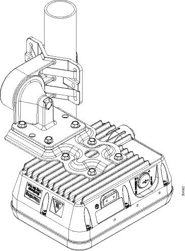
Figure 2-5 AP Mounted on a Pole
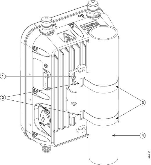
Pole Mounting the Access Point with the AIR-ACC1560-PMK1= Kit
The AIR-ACC1560-PMK1= fixed mounting kit contains a mounting bracket, for both wall-mounting and pole-mounting, the access point along with the power supply kit. This mounting kit supports metal, wood or fiberglass poles from 2 to 8 inches in diameter.
Table 2-4 Materials Needed to Mount the AP
To mount the access point onto a vertical pole or streetlight pole, follow these steps:
Step 1![]() Select a mounting location on the pole to mount the access point. You can attach the access point to a pole having a diameter of 2 to 8 inches (5.1 to 20.1 cm).
Select a mounting location on the pole to mount the access point. You can attach the access point to a pole having a diameter of 2 to 8 inches (5.1 to 20.1 cm).
Note![]() If you will be using a streetlight power tap adapter, position the access point within 3 ft (1 m) of the outdoor light control. An AC/DC adapter needs to be used for street light pole deployments.
If you will be using a streetlight power tap adapter, position the access point within 3 ft (1 m) of the outdoor light control. An AC/DC adapter needs to be used for street light pole deployments.
Step 2![]() Hold the bracket up against the pole, and slide the three band straps through the top, middle, and bottom sets of mounting slots on the mounting bracket (see Figure 2-6).
Hold the bracket up against the pole, and slide the three band straps through the top, middle, and bottom sets of mounting slots on the mounting bracket (see Figure 2-6).
Step 3![]() Wrap the band straps around the pole, lock them and then lightly tighten the clamps using a wrench. Only tighten them enough to keep the bracket from sliding down the pole
Wrap the band straps around the pole, lock them and then lightly tighten the clamps using a wrench. Only tighten them enough to keep the bracket from sliding down the pole
Step 4![]() Screw an M6 bolt into each of the four bolt holes on the back side of the access point. Do not screw the bolt in all the way. Leave a gap of about 0.13" (3.3mm).
Screw an M6 bolt into each of the four bolt holes on the back side of the access point. Do not screw the bolt in all the way. Leave a gap of about 0.13" (3.3mm).
Step 5![]() Position the four bolts on the access point into the bracket keyhole slots. Check to be sure that the access point is properly seated in the slots (see Figure 2-6).
Position the four bolts on the access point into the bracket keyhole slots. Check to be sure that the access point is properly seated in the slots (see Figure 2-6).
Note![]() The access point should be mounted with the status LED on the base facing downwards.
The access point should be mounted with the status LED on the base facing downwards.
Step 6![]() Using a 10mm wrench, tighten the four bolts that connect the access point to the bracket to a torque of 40 lbf-in.
Using a 10mm wrench, tighten the four bolts that connect the access point to the bracket to a torque of 40 lbf-in.
Step 7![]() Mount the power supply to the bracket with four #8-32 screws.
Mount the power supply to the bracket with four #8-32 screws.
Step 8![]() Locate the access point to its final position. Tighten the band clamps with the wrench. Ensure that the clamps are tight enough to not let the AP move.
Locate the access point to its final position. Tighten the band clamps with the wrench. Ensure that the clamps are tight enough to not let the AP move.
Step 9![]() Continue with the Grounding the Access Point.
Continue with the Grounding the Access Point.
Figure 2-6 AP and Power Supply Mounted on a Pole
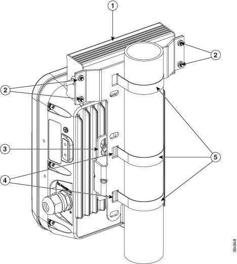
|
|
|
||
|
|
|
||
|
|
One of four M6 keyhole slots for mounting the AP on the bracket. |
|
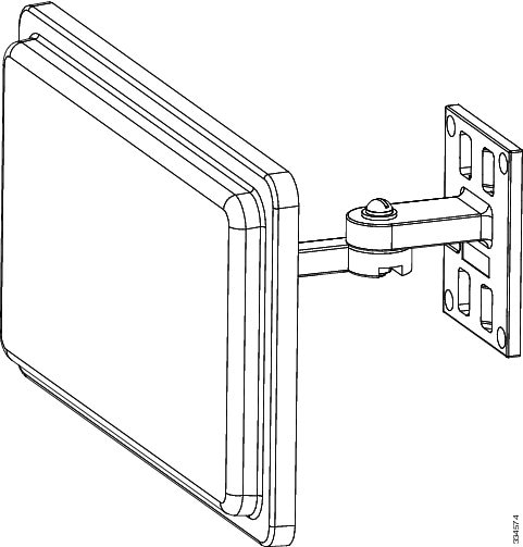
Wall Mounting the AP using AIR-ACC1530-PMK2= Pivoting Mounting Kit
The optional pivoting mounting kit AIR-ACC1530-PMK2= contains a pivoting mounting bracket for both wall and pole mounting. This kit allows for adjusting the position of the AP by pivoting the AP along its vertical plane.
Table 2-5 Materials for Mounting on Wall with Pivoting Mounting Kit
To mount the access point vertically on a wall, follow these instructions:
Step 1![]() Disassemble the pivot kit, if not already disassembled. See Figure 2-7.
Disassemble the pivot kit, if not already disassembled. See Figure 2-7.
Step 2![]() Use the wall-plate end of the mounting bracket as a template to mark four screw hole locations on the mounting surface. See Figure 2-7 for the mounting bracket screw hole locations (screw holes of maximum 6 mm in size).
Use the wall-plate end of the mounting bracket as a template to mark four screw hole locations on the mounting surface. See Figure 2-7 for the mounting bracket screw hole locations (screw holes of maximum 6 mm in size).
See Figure 2-8 for the dimensions of the pivoting mounting bracket.
Step 3![]() Use four screws and, if required, wall anchors to attach the wall-plate end of the mounting bracket to the mounting surface. These screws and anchors are to be sourced independently.
Use four screws and, if required, wall anchors to attach the wall-plate end of the mounting bracket to the mounting surface. These screws and anchors are to be sourced independently.
Note![]() You can use an exterior-grade plywood backboard to mount the access point to stucco, cement, or drywall.
You can use an exterior-grade plywood backboard to mount the access point to stucco, cement, or drywall.
Note![]() The mounting wall, attaching screws, and wall anchors must be able to support a 50-lb (22.7 kg) static weight.
The mounting wall, attaching screws, and wall anchors must be able to support a 50-lb (22.7 kg) static weight.
Step 4![]() Align the AP-plate end of the bracket with the screw holes in the back of the access point.
Align the AP-plate end of the bracket with the screw holes in the back of the access point.
Step 5![]() Fasten the bracket plate to the AP by using four M6 x12 mm bolts and a 10 mm box or socket wrench. Torque the bolts to 40 lbf-in.
Fasten the bracket plate to the AP by using four M6 x12 mm bolts and a 10 mm box or socket wrench. Torque the bolts to 40 lbf-in.
Step 6![]() Using the 90.0 mm M8 long screw and the hardware supplied with the pivoting bracket, bolt the AP and bracket plate, to the wall plate mounted on the wall. See Figure 2-7 for this assembly. Do not fully tighten the assembly.
Using the 90.0 mm M8 long screw and the hardware supplied with the pivoting bracket, bolt the AP and bracket plate, to the wall plate mounted on the wall. See Figure 2-7 for this assembly. Do not fully tighten the assembly.
Note![]() The access point should be mounted with the status LED on the base facing downwards.
The access point should be mounted with the status LED on the base facing downwards.
Step 7![]() Pivot the AP as required, and then fully tighten the 90.0 mm M8 long screw using a 13 mm wrench.
Pivot the AP as required, and then fully tighten the 90.0 mm M8 long screw using a 13 mm wrench.
Step 8![]() Proceed with installing antennas (only for external antenna models), connecting the data cables, grounding the access point, powering and configuring the access point..
Proceed with installing antennas (only for external antenna models), connecting the data cables, grounding the access point, powering and configuring the access point..
Figure 2-7 Pivoting Mounting Bracket
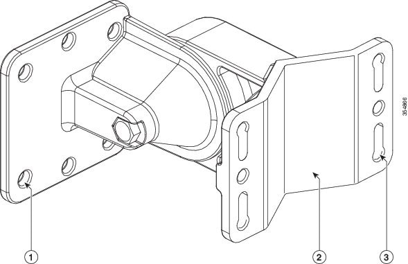
Figure 2-8 Pivoting Mounting Bracket Dimensions
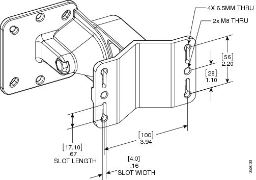
Figure 2-9 Exploded View of the Pivoting Mounting Kit
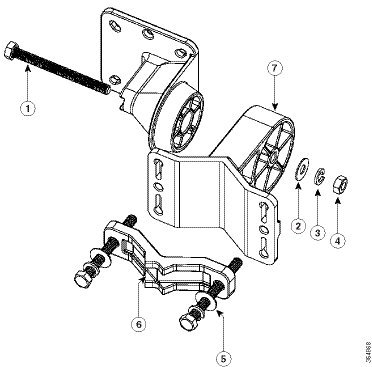
|
|
|
80.0 mm M8 screw with washer and spring washer, for fastening the pole-mount screw clamp to the pivoting bracket base plate. |
|
|
|
|||
|
|
|
||
|
|
|
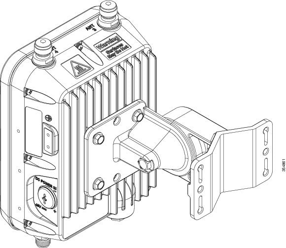
Figure 2-10 Visualization of AP Fastened to the Pivoting Mounting Kit
Pole Mounting the AP using AIR-ACC1530-PMK2= Pivoting Mounting Kit
The optional pivoting mounting kit AIR-ACC1530-PMK2= contains a pivoting mounting bracket for both wall and pole mounting. This kit can be used to install the access point on a pole, mast, or streetlight. It supports metal, wood or fiberglass poles from 2 to 8 inches in diameter.
The AIR-ACC1530-PMK2= pivoting mounting kit allows for adjusting the position of the AP by pivoting the AP along its vertical plane.
To mount the access point on a pole, follow these steps:
Step 1![]() Select a mounting location on the pole to mount the access point. You can attach the access point to any pole with a diameter from 2 to 8 inches (5.1 to 40.6 cm).
Select a mounting location on the pole to mount the access point. You can attach the access point to any pole with a diameter from 2 to 8 inches (5.1 to 40.6 cm).
Note![]() If you will be using a streetlight power tap adapter, position the access point within 3 ft (1 m) of the outdoor light control.
If you will be using a streetlight power tap adapter, position the access point within 3 ft (1 m) of the outdoor light control.
Step 2![]() Disassemble the pivot kit, if not already disassembled. See Figure 2-7.
Disassemble the pivot kit, if not already disassembled. See Figure 2-7.
Step 3![]() Fasten the pivot bracket base plate to the pole using either one set of the adjustable band clamps or the screw clamp (the screw clamp can be used only on poles that are 2-3 inches (50-76 mm) in diameter).
Fasten the pivot bracket base plate to the pole using either one set of the adjustable band clamps or the screw clamp (the screw clamp can be used only on poles that are 2-3 inches (50-76 mm) in diameter).
Step 4![]() Position the pivot bracket base plate and clamp(s) on the pole. Tighten only enough to hold the bracket base plate in place, so as to prevent it from sliding along the pole but still pivot on the pole. Fully tighten only after the access point is mounted and positioned.
Position the pivot bracket base plate and clamp(s) on the pole. Tighten only enough to hold the bracket base plate in place, so as to prevent it from sliding along the pole but still pivot on the pole. Fully tighten only after the access point is mounted and positioned.
Step 5![]() Align the AP-plate end of the bracket with the screw holes in the back of the access point.
Align the AP-plate end of the bracket with the screw holes in the back of the access point.
Step 6![]() Fasten the bracket plate to the AP by using four M6 x12 mm bolts and a 10 mm box or socket wrench. Torque the bolts to 40 lbf-in (4.5Nm).
Fasten the bracket plate to the AP by using four M6 x12 mm bolts and a 10 mm box or socket wrench. Torque the bolts to 40 lbf-in (4.5Nm).
Step 7![]() Using the 90.0 mm M8 long screw and the hardware supplied with the pivoting bracket, bolt the AP and bracket plate, to the base plate mounted on the pole. See Figure 2-10 for this assembly. Do not fully tighten the assembly.
Using the 90.0 mm M8 long screw and the hardware supplied with the pivoting bracket, bolt the AP and bracket plate, to the base plate mounted on the pole. See Figure 2-10 for this assembly. Do not fully tighten the assembly.
Note![]() The access point should be mounted with the status LED on the base facing downwards.
The access point should be mounted with the status LED on the base facing downwards.
Step 8![]() Pivot and position the AP as required, and then fully tighten the 90.0 mm M8 long screw using a 13 mm wrench, and then tighten the clamps on the pole.
Pivot and position the AP as required, and then fully tighten the 90.0 mm M8 long screw using a 13 mm wrench, and then tighten the clamps on the pole.
Note![]() Use caution when tightening the 80 mm bolts on the pole-mount screw clamp. See Figure 2-9. Ensure the clamp face remains parallel to the bracket base plate while tightening the bolts. Torque the M8 x 80 mm bolts to 52-61 lbf-in (5.9-6.9 Nm).
Use caution when tightening the 80 mm bolts on the pole-mount screw clamp. See Figure 2-9. Ensure the clamp face remains parallel to the bracket base plate while tightening the bolts. Torque the M8 x 80 mm bolts to 52-61 lbf-in (5.9-6.9 Nm).
Step 9![]() Proceed with installing antennas (only for external antenna models), connecting the data cables, grounding the access point, powering and configuring the access point.
Proceed with installing antennas (only for external antenna models), connecting the data cables, grounding the access point, powering and configuring the access point.
Figure 2-11 Pivoting Mounting Kit with Pole Mount Clamp
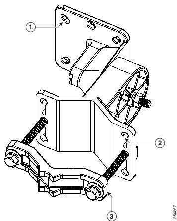
|
|
One of four mounting holes for the access point. This is the AP-plate end of the bracket, and is fastened to the back of the AP. |
|
Pole mount screw clamp. It can fit poles having a diameter of up to 2-3 in. (50-76mm). |
|
|
One of four slots for band clamps. This is the pivot bracket base plate, and is fastened to the pole. Pole mount installation using band clamps are shown in Figure 2-12. |
|
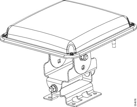
Figure 2-12 AP Wall Mounted Using the Pivoting Mounting Bracket
|
|
One of four mounting holes for mounting the access point to the bracket. |
|
|
|
|
|
Horizontally Mounting the Access Point using AIR-ACC1530-PMK2=
The AIR-ACC1530-PMK2= pivoting pole mount kit contains a horizontal mount plate that allows the AP to be mounted horizontally, as shown in Figure 2-14. The horizontal mounting provides better omni antenna coverage.
To mount the AP horizontally using AIR-ACC1530-PMK2=, follow these steps:
Step 1![]() Mount the pivot bracket to a wall or a pole as shown in the previous procedures. However, stop before mounting the pivot bracket plate directly to the access point.
Mount the pivot bracket to a wall or a pole as shown in the previous procedures. However, stop before mounting the pivot bracket plate directly to the access point.
Step 2![]() Using four M6 x 12 mm bolts, fasten the horizontal adapter plate to the pivot bracket plate.
Using four M6 x 12 mm bolts, fasten the horizontal adapter plate to the pivot bracket plate.
Step 3![]() Using the remaining four M6 x 12 mm bolts, mount the other side of the horizontal mounting plate to the AP. See Figure 2-13 for the exploded view.
Using the remaining four M6 x 12 mm bolts, mount the other side of the horizontal mounting plate to the AP. See Figure 2-13 for the exploded view.
Step 4![]() Using a 10 mm wrench or socket, tighten all M6 bolts to 40 lbf-in (4.5 Nm).
Using a 10 mm wrench or socket, tighten all M6 bolts to 40 lbf-in (4.5 Nm).
Step 5![]() Position and orient the access point as needed and tighten the mount kit bolts using a 13 mm wrench or socket. See Figure 2-14.
Position and orient the access point as needed and tighten the mount kit bolts using a 13 mm wrench or socket. See Figure 2-14.
Figure 2-13 Exploded View of the Pivot Bracket Parts with Horizontal Mount Plate
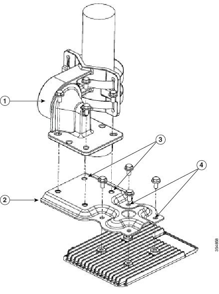
|
|
|
Two out of four screw holes for mounting the horizontal mounting plate to the pivoting bracket. |
|
|
|
|
Two out of four screw holes for mounting the access point to the horizontal mounting plate. |
Figure 2-14 Access Point Horizontally Mounted using the Optional Horizontal Mount Plate
Installing AP Cover AIR-ACC1560-CVR=
You can install a cover AIR-ACC1560-CVR=, which also acts as a a solar shield. The cover can be installed prior to or after all connections are made. However, if remote cabled antennas are to be installed, the shield must be installed before the antenna cables are attached to the AP.
Step 1![]() This step applies only to AP1562D models.
This step applies only to AP1562D models.
The cover AIR-ACC1560-CVR= is factory fitted with an adapter for installing on AP models AP1562I and AP1562E. You need to remove this adapter before installing the cover on AP1562D AP models. For this:
a.![]() Slide a large flat blade screw driver into the opening shown in Figure 2-15.
Slide a large flat blade screw driver into the opening shown in Figure 2-15.
b.![]() Pry up the adapter while pushing the screw driver further into it, until the adapter pop out.
Pry up the adapter while pushing the screw driver further into it, until the adapter pop out.
Step 2![]() Position and slide the cover over the AP as shown in Figure 2-16.
Position and slide the cover over the AP as shown in Figure 2-16.
Step 3![]() Align the two holes on each side of the cover with the screw holes on corresponding side of the AP.
Align the two holes on each side of the cover with the screw holes on corresponding side of the AP.
Step 4![]() Insert and install #8-32 screws through the screw holes in the cover and into the AP. Tighten the screws to 10 lb-in.
Insert and install #8-32 screws through the screw holes in the cover and into the AP. Tighten the screws to 10 lb-in.
Figure 2-15 Only for AP1562D - Removing the Adapter from the Cover
|
|
Slide a large flat blade screw driver into this opening and the pry the adapter out. |
||
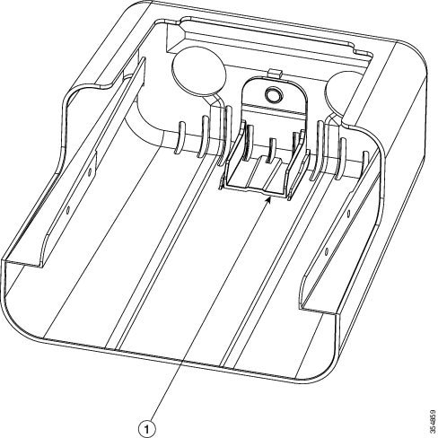
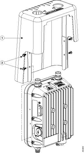
Figure 2-16 Installing the Cover on the AP
|
|
|
Installing External Antennas
Note![]() When operating in the 5GHz UNII-1 band, all Omni Directional antennas should be installed vertically, and all directional antennas should be installed with the main beam aimed parallel to or tilted down toward the horizon.
When operating in the 5GHz UNII-1 band, all Omni Directional antennas should be installed vertically, and all directional antennas should be installed with the main beam aimed parallel to or tilted down toward the horizon.
Table 2-8 shows the external antennas supported by the 1562E access point and provides required quantities for each model.
|
|
|
|
|
|---|---|---|---|
For installation instructions and detailed information on any of these antennas, refer to the antenna guide at:
http://www.cisco.com/c/en/us/support/wireless/aironet-antennas-accessories/products-installation-guides-list.html
Follow all safety precautions when installing the antennas. For information on safety, refer to “Safety Precautions when Installing Antennas” section.
Non-Cisco Antennas
Cisco does not support any third-party antennas. RF connectivity and compliance of third party antennas is the user’s responsibility. Cisco does not recommend any third-party antennas, and Cisco Technical Assistance Center will not be able to provide any support for third-party antennas. Cisco’s FCC Part 15 compliance is only guaranteed with Cisco antennas or antennas that are of the same design and gain as Cisco antennas.
Cisco Flexible Antenna Port
The Cisco Flexible Antenna Port feature on the 1562 series access points allows support for either dual-band or single-band antennas on the same AP. This is configurable using a CLI command from the wireless LAN controller.
To have dual-band ports, use the two antenna ports on the base (ports 1 and 2) to connect to dual-band omni or directional antennas.
To have single-band ports, use two separate 2.4 GHz and two 5 GHz antenna ports.
External Antenna Mounting Configurations
The selection of the antenna is determined in the configuration of the product. The 1562E antennas can be mounted on a wall, pole and/or tower mounted. Always refer to the Ordering Guide for the updated list of supported antennas.
The 1562E access point supports a variety of antennas designed for outdoor use with radios operating in the 2.4-GHz and 5-GHz frequency bands. The 1562E supports the external antennas listed in the following sections.
Cisco Aironet Dual-Band Omnidirectional Antenna (AIR-ANT2547V-N, AIR-ANT2547VG-N)
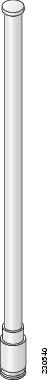
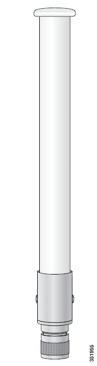
The Dual-Band Omnidirectional Antenna, referred to as a “stick” antenna, is designed for outdoor use with Cisco Aironet Outdoor Access Points with radios operating in the 2.4-GHz and 5-GHz frequency bands (Figure 2-17). Basic operating features of the antenna are:
The antenna is designed to create an omnidirectional broadcast pattern. To achieve this pattern, mount the access point clear of any obstructions to the sides of the radiating element.
For detailed information on this antenna, refer to the Cisco Aironet Dual-Band Omnidirectional Antenna (AIR-ANT2547V-N, AIR-ANT2547VG-N) document. Follow all safety precautions when installing the antennas. For information on safety, refer to “Safety Precautions when Installing Antennas” section.
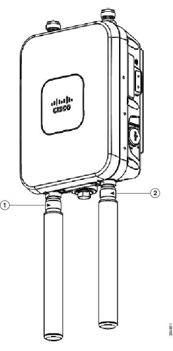
Figure 2-17 Cisco Aironet Dual-Band Omnidirectional Antenna - Installed Only on Model AIR-AP1562E-x-K9
|
|
Antenna connected to antenna port 1(Type-N connector) (TX/RX) |
|
Antenna connected to antenna port 2(Type-N connector) (TX/RX) |
Cisco Aironet 2.4-GHz/5-GHz 8-dBi Directional Antenna (AIR-ANT2588P3M-N)
The Cisco Aironet 2.4-GHz/5-GHz 8-dBi Directional Antenna is designed for outdoor use with Cisco Aironet Outdoor Access Points with radios operating in both the 2.4-GHz and 5-GHz frequency bands. This antenna has 8-dBi gain in both bands.
For detailed information on this antenna, refer to the Cisco Aironet 2.4-GHz/5-GHz 8-dBi Directional Antenna (AIR-ANT2588P3M-N) document. Follow all safety precautions when installing the antennas, for information on safety, refer to “Safety Precautions when Installing Antennas” section.
Figure 2-18 Cisco Aironet 2.4-GHz/5-GHz 8-dBi Directional Antenna - Installed Only on Model AIR-AP1562E-x-K9
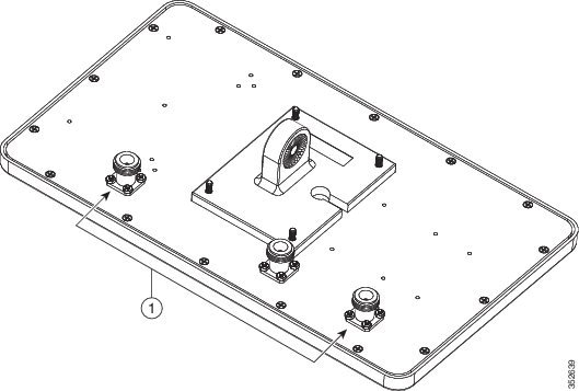
Note![]() When installing the AIR-ANT2588P3M-N with the Cisco Aironet 1560 Series AP, connect the outermost antenna ports (marked ‘1’ in Figure 2-19) to the AP’s dual band antenna ports.
When installing the AIR-ANT2588P3M-N with the Cisco Aironet 1560 Series AP, connect the outermost antenna ports (marked ‘1’ in Figure 2-19) to the AP’s dual band antenna ports.
Figure 2-19 Antenna Ports For Connection to AP’s Dual Band Ports
Cisco Aironet 5-GHz 14-dBi 2-Port Directional Antenna (AIR-ANT5114P2M-N)
The Cisco Aironet 5-GHz 14-dBi 2-Port Directional Antenna is designed for outdoor use with Cisco Aironet Outdoor Access Points with radios operating in the 5-GHz frequency band. This antenna has 14-dBi in the 5-GHz band.
For more information, see the Cisco Aironet 5-GHz 14-dBi Directional Antenna document, at the following URL:
http://www.cisco.com/c/en/us/td/docs/wireless/antenna/installation/guide/ant5114p2m-n.html.
For detailed information on this antenna, see the Cisco Aironet 5-GHz 14-dBi Directional Antenna (AIR-ANT5114P2M-N) document. Follow all safety precautions when installing the antennas, for information on safety, refer to “Safety Precautions when Installing Antennas” section.
Figure 2-20 Cisco Aironet 5-GHz 14-dBi Directional Antenna - Installed Only on Models AIR-AP1562E-x-K9
Cisco Aironet 2.4-GHz 13-dBi 2-Port Directional Antenna (AIR-ANT2413P2M-N)
The Cisco Aironet 2.4-GHz 13-dBi 2-Port Directional Antenna is designed for outdoor use with Cisco Aironet Outdoor Access Points with radios operating in the 2.4-GHz frequency band. This antenna has 13-dBi gain in the 2.4-GHz frequency band.
For detailed information on this antenna, refer to the Cisco Aironet 2.4-GHz 13-dBi Directional Antenna (AIR-ANT2413P2M-N) document. Follow all safety precautions when installing the antennas, for information on safety, refer to “Safety Precautions when Installing Antennas” section.
Figure 2-21 Cisco Aironet 2.4-GHz 13-dBi Directional Antenna - Installed Only on Models AIR-AP1562E-x-K9
Cisco Aironet 2.4-GHz 5-dBi Omnidirectional Antenna (AIR-ANT2450V-N)
The Cisco Aironet 2.4-GHz 5-dBi Omnidirectional Antenna is designed for outdoor use with Cisco Aironet Outdoor Access Points with radios operating in the 2.4-GHz frequency band. This antenna has a 5-dBi gain in the 2.4-GHz band.
For detailed information on this antenna, refer to the document Cisco Aironet 5-dBI Omnidirectional Antenna (AIR-ANT2450V-N). Follow all safety precautions when installing the antennas. For information on safety, refer to “Safety Precautions when Installing Antennas” section.
Figure 2-22 Cisco Aironet 2.4-GHz 5-dBi Omni Antenna - Installed Only on Model AIR-AP1562E-x-K9
Cisco Aironet 2.4-GHz 8-dBi Omnidirectional Antenna (AIR-ANT2480V-N)
The Cisco Aironet 2.4-GHz 8-dBi Omnidirectional Antenna is designed for outdoor use with Cisco Aironet Outdoor Access Points with radios operating in the 2.4-GHz frequency band. This antenna has 8-dBi gain in the 2.4-GHz frequency band.
For detailed information on this antenna, refer to the document Cisco Aironet 8-dBi Omnidirectional Antenna (AIR-ANT2480V-N). Follow all safety precautions when installing the antennas, for information on safety, refer to “Safety Precautions when Installing Antennas” section.
Figure 2-23 Cisco Aironet 2.4-GHz 8-dBi Omni Antenna - Installed Only on Model AIR-AP1562E-x-K9i
Cisco Aironet 5-GHz 8-dBi Omnidirectional Antenna (AIR-ANT5180V-N)
The Cisco Aironet 5-GHz 8-dBi Omnidirectional Antenna is designed for outdoor use with Cisco Aironet Outdoor Access Points with radios operating in the 5-GHz frequency band. This antenna has 8-dBi gain in the 5-GHz frequency band.
For detailed information on this antenna, refer to the document Cisco Aironet 8-dBi Omnidirectional Antenna (AIR-ANT5180V-N). Follow all safety precautions when installing the antennas, for information on safety, refer to “Safety Precautions when Installing Antennas” section.
Figure 2-24 Cisco Aironet 5-GHz 8-dBi Omnidirectional Antenna - Installed Only on Model AIR-AP1562E-x-K9
Using a Mounting Bracket for External Directional Antennas
You can use the AIR-ACCAMK-2= bracket for mounting a directional antenna directly on the access point. See Figure 2-25.
Figure 2-25 Directional Antenna Mounting Bracket AIR-ACCAMK-2= Views
Installing a Lightning Arrestor
Overvoltage transients can be created through lightning static discharges, switch processes, direct contact with power lines, or through earth currents. The Cisco Aironet AIR-ACC245LA-N Lightning Arrestor limits the amplitude and duration of disturbing interference voltages and improves the over voltage resistance of in-line equipment, systems, and components. A lightning arrestor installed according to these mounting instructions balances the voltage potential, thus preventing inductive interference to parallel signal lines within the protected system.
Installation Considerations
Cisco recommends that you bulkhead mount the lightning arrestor so it can be installed as a wall-feed through on the wall of the protected space.
The importance of obtaining a good ground and bonding connection cannot be overstressed. Consider these points when grounding the lightning arrestor:
Installation Notes
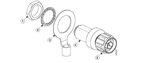
This lightning arrestor is designed to be installed between the antenna cable that is attached to an outdoor antenna and the Cisco Aironet wireless device. You can install the lightning arrestor either indoors or outdoors. It can be connected directly to a wireless device having an external N connector. It can also be mounted inline or as a feed-through. Feed-through installations require 5/8 in. (16 mm) hole to accommodate the lightning arrestor.
Note![]() This lightning arrestor is part of a lightning arrestor kit. The kit contains a lightning arrestor and a grounding lug.
This lightning arrestor is part of a lightning arrestor kit. The kit contains a lightning arrestor and a grounding lug.
Note![]() When you install the lightning arrestor, follow the regulations or best practices applicable to lightning protection installation in your local area.
When you install the lightning arrestor, follow the regulations or best practices applicable to lightning protection installation in your local area.
Installing the Lightning Arrestor Outdoors
If you install the lightning arrestor outdoors, use the supplied ground lug and a heavy wire (#6 solid copper) to connect it to a good earth ground, such as a ground rod. The connection should be as short as possible.
Figure 2-26 Lightning Arrestor Details
|
|
|
||
|
|
|
||
|
|
|||
Cable for the Lightning Arrestor
Coaxial cable loses efficiency as the frequency increases, resulting in signal loss. The cable should be kept as short as possible because cable length also determines the amount of signal loss (the longer the run, the greater the loss).
Cisco recommends a high-quality, low-loss cable for use with the lightning arrestor.
Grounding the Access Point
The access point must be grounded before connecting power.
In all outdoor installations you must follow these instructions to properly ground the case:
Step 1![]() If using insulated 6-AWG copper ground wire, strip the insulation as required for the grounding lug.
If using insulated 6-AWG copper ground wire, strip the insulation as required for the grounding lug.
Step 2![]() Use the appropriate crimping tool to crimp the bare 6-AWG copper ground wire to the supplied grounding lug.
Use the appropriate crimping tool to crimp the bare 6-AWG copper ground wire to the supplied grounding lug.
Note![]() The grounding lug and hardware used must comply with local and national electrical codes.
The grounding lug and hardware used must comply with local and national electrical codes.
Step 3![]() Open the anti-corrosion sealant (supplied), and apply a liberal amount over the metal surface, called the Ground Pad, where the ground strap screw holes are located (see Figure 2-27).
Open the anti-corrosion sealant (supplied), and apply a liberal amount over the metal surface, called the Ground Pad, where the ground strap screw holes are located (see Figure 2-27).
Step 4![]() Connect the grounding lug to the access point grounding screw holes (see Figure 2-27) using the supplied two Phillips head screws (M4 x10 mm) with lock washers. Tighten the grounding screw to 22 to 24 lb-in (2.49 to 2.71 Nm).
Connect the grounding lug to the access point grounding screw holes (see Figure 2-27) using the supplied two Phillips head screws (M4 x10 mm) with lock washers. Tighten the grounding screw to 22 to 24 lb-in (2.49 to 2.71 Nm).
Step 5![]() If necessary, strip the other end of the ground wire and connect it to a reliable earth ground, such as a grounding rod or an appropriate grounding point on a metal streetlight pole that is grounded.
If necessary, strip the other end of the ground wire and connect it to a reliable earth ground, such as a grounding rod or an appropriate grounding point on a metal streetlight pole that is grounded.
Figure 2-27 Position of the Ground Pad on the Right Side of the AP
|
|
|||
Powering the Access Point
The 1560 access point supports these power sources:
The 1560 access point can be powered via the PoE input from an in-line power injector or a suitably powered switch port. Depending on the configuration and regulatory domain, the required power for full operation is UPoE.
For the 1562I, UPoE powered switch port or a power injector is required for full operation of the 3x3 MIMO on the 2.4 GHz radio in the regulatory domains that allow for high 2.4 GHz transmit power (Regulatory domains -A, -D, -F, -K, -N, -Q, -T, -Z). If the 1562I is powered by a PoE+ (802.3at power) switch port then the access point will automatically disable one of the 2.4 GHz transmitters and the radio will operate in 2x2 MIMO mode.
Table 2-9 AP 1560 Power Matrix
|
|
|
|
|
|
|
|
|---|---|---|---|---|---|---|
|
2.The AIR-PWRINJ6 power injector can only be used in an indoor environment. Therefore the cable from the injector must travel from the protected location to the outside mounted access point. |
Connecting a Power Injector
The 1560 Series access point supports the following power injectors:
The power injector provides 56 VDC to the access point over the Ethernet cable and supports a total end-to-end Ethernet cable length of 100 m (328 ft) from the switch to the access point.
When your access point is powered by an optional power injector, follow these steps to complete the installation:
Step 1![]() Before applying PoE to the access point, ensure that the access point is grounded (see the “Grounding the Access Point” section).
Before applying PoE to the access point, ensure that the access point is grounded (see the “Grounding the Access Point” section).
Step 2![]() See the “Typical Access Point Installation Components” section, to identify the components needed for the installation.
See the “Typical Access Point Installation Components” section, to identify the components needed for the installation.
Step 3![]() Connect a CAT5e or better Ethernet cable from your wired LAN network to the power injector.
Connect a CAT5e or better Ethernet cable from your wired LAN network to the power injector.

Warning![]() To reduce the risk of fire, use only No. 26 AWG or larger telecommunication line cord. Statement 1023
To reduce the risk of fire, use only No. 26 AWG or larger telecommunication line cord. Statement 1023
Note![]() The installer is responsible for ensuring that powering the access point from this type of power injector is allowed by local and/or national safety and telecommunications equipment standards.
The installer is responsible for ensuring that powering the access point from this type of power injector is allowed by local and/or national safety and telecommunications equipment standards.

Tip To forward bridge traffic, add a switch between the power injector and controller. Refer to the Cisco Wireless Mesh Access Points, Design and Deployment Guide, Release 7.0 for more information.
Step 4![]() Ensure that the antennas are connected and that a ground is attached to the access point before you apply power to the access point.
Ensure that the antennas are connected and that a ground is attached to the access point before you apply power to the access point.
Step 5![]() Connect a shielded outdoor-rated Ethernet (CAT5e or better) cable between the power injector and the PoE-in connector of the access point.
Connect a shielded outdoor-rated Ethernet (CAT5e or better) cable between the power injector and the PoE-in connector of the access point.
Step 6![]() Connect the Ethernet cable to the access point PoE-In port. See “Connecting an Ethernet Cable to the Access Point” section.
Connect the Ethernet cable to the access point PoE-In port. See “Connecting an Ethernet Cable to the Access Point” section.
Connecting a DC Power Cable to the Access Point
When powering the access point with DC power, you must ensure that DC power can be conveniently removed from the unit. The power should not be removed by disconnecting the DC power connector on the unit.
Warning![]() Connect the unit only to DC power source that complies with the safety extra-low voltage (SELV) requirements in IEC 60950 based safety standards. Statement 1033
Connect the unit only to DC power source that complies with the safety extra-low voltage (SELV) requirements in IEC 60950 based safety standards. Statement 1033
To connect a DC power cable, you need to supply these tools and material:
- Shielded outdoor-rated DC power cable (minimum 18 AWG) with outside cable diameter of 0.20 to 0.35 inch (0.51 to 0.89 cm).
- Adjustable or open-end wrench
- Small flat screw driver
- Two-pin DC power connector (Cisco supplied)
To connect the DC power cable to the access point, follow these steps:
Step 1![]() Before connecting DC power to the access point, ensure that the ground is connected to the access point. See the “Grounding the Access Point” section.
Before connecting DC power to the access point, ensure that the ground is connected to the access point. See the “Grounding the Access Point” section.
Step 2![]() Turn off all power sources to the access point, including the DC power source.
Turn off all power sources to the access point, including the DC power source.
Warning![]() This unit might have more than one power supply connection. All connections must be removed to de-energize the unit. Statement 1028
This unit might have more than one power supply connection. All connections must be removed to de-energize the unit. Statement 1028
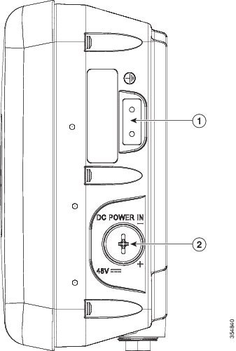
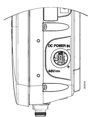
Step 3![]() Use a large Phillips or Flat Blade screw driver to remove the covering plug of the DC Power-In port. Do not discard plug and rubber seal unless you are certain that the port will not have to be re-plugged. (see Figure 2-28 for the location of the DC power connector).
Use a large Phillips or Flat Blade screw driver to remove the covering plug of the DC Power-In port. Do not discard plug and rubber seal unless you are certain that the port will not have to be re-plugged. (see Figure 2-28 for the location of the DC power connector).
Figure 2-28 Position of the DC Power-In Port on the Right Side of the AP
|
|
|
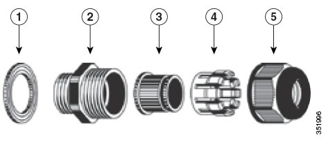
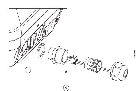
Step 4![]() Loosen the thread-lock sealing nut of the cable gland by turning it counter clockwise, but do not remove it (see Figure 2-29).
Loosen the thread-lock sealing nut of the cable gland by turning it counter clockwise, but do not remove it (see Figure 2-29).
Note![]() Verify that the cable gland has a rubber seal and ensure that it is not damaged.
Verify that the cable gland has a rubber seal and ensure that it is not damaged.
Warning![]() Failure to install the Cable Gland properly will cause the cable grip to leak.
Failure to install the Cable Gland properly will cause the cable grip to leak.
|
|
|
||
|
|
|
||
|
|
|
Note![]() The cable gland accepts a cable diameter of 0.20 to 0.35 in. (0.51 to 0.89 cm).
The cable gland accepts a cable diameter of 0.20 to 0.35 in. (0.51 to 0.89 cm).
Step 5![]() Insert a bare end of the DC power cable into the rounded end of the cable gland (see Figure 2-29), and pull approximately 6 inches of cable through the adapter.
Insert a bare end of the DC power cable into the rounded end of the cable gland (see Figure 2-29), and pull approximately 6 inches of cable through the adapter.
Warning![]() When installing the DC power cable, ensure that cable gland and the rubber gasket are present and installed properly, to avoid water leakage into the enclosure. See Figure 2-29 and Figure 2-32.
When installing the DC power cable, ensure that cable gland and the rubber gasket are present and installed properly, to avoid water leakage into the enclosure. See Figure 2-29 and Figure 2-32.
Step 6![]() Strip the DC cable jacket back by about 1 inch to expose the wires and then strip the insulation by about 0.5 inch (or 12 mm) from each wire.
Strip the DC cable jacket back by about 1 inch to expose the wires and then strip the insulation by about 0.5 inch (or 12 mm) from each wire.
Step 7![]() Push in the orange colored spring-loaded securing tabs and insert the wire (see Figure 2-30) all the way into the two-position terminal block connector (Cisco Part Number 29-100226-01, Figure 2-31), and then release the tabs. Tug on the wire to ensure that it is properly secured.
Push in the orange colored spring-loaded securing tabs and insert the wire (see Figure 2-30) all the way into the two-position terminal block connector (Cisco Part Number 29-100226-01, Figure 2-31), and then release the tabs. Tug on the wire to ensure that it is properly secured.
Figure 2-30 Push in the securing tab, and wire, as the arrow shows
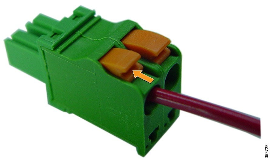
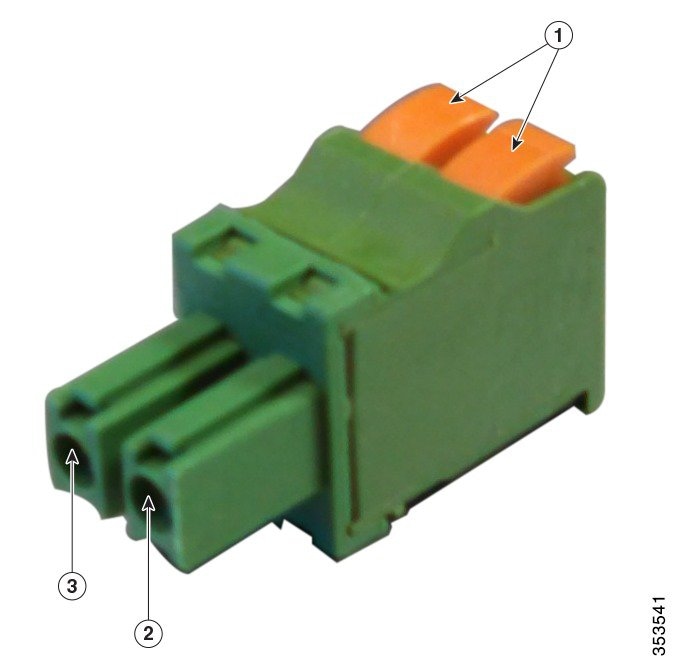
Figure 2-31 Two-Position Terminal Block Connector
|
|
|
||
|
|
|
Step 9![]() Insert the two-position terminal strip into the DC power opening in the access point case, and carefully push the terminal strip into the internal connector (see Figure 2-32).
Insert the two-position terminal strip into the DC power opening in the access point case, and carefully push the terminal strip into the internal connector (see Figure 2-32).
Note![]() Ensure that the polarity of the terminal strip properly matches the polarity markings on the enclosure (see Figure 2-33)
Ensure that the polarity of the terminal strip properly matches the polarity markings on the enclosure (see Figure 2-33)
Figure 2-32 Inserting the Terminal Strip into the DC Power Opening in the Access Point Case
|
|
DC power opening in access point case. Also see Figure 2-33. |
|
Figure 2-33 DC Power Opening in the Access Point Case
Step 10![]() Slide the cable gland with the rubber seal towards the access point, and screw the threaded end of the body into the access point, and hand-tighten.
Slide the cable gland with the rubber seal towards the access point, and screw the threaded end of the body into the access point, and hand-tighten.
Step 11![]() Use an adjustable wrench, a 28-mm wrench to tighten the threaded end of the body to 15 lb-in.
Use an adjustable wrench, a 28-mm wrench to tighten the threaded end of the body to 15 lb-in.
Step 12![]() Use an adjustable wrench and tighten the thread-lock seal nut to 15 lb-in.
Use an adjustable wrench and tighten the thread-lock seal nut to 15 lb-in.
Step 13![]() Ensure that the antennas are connected to the access point before you apply power to the access point.
Ensure that the antennas are connected to the access point before you apply power to the access point.
Step 14![]() Turn on the DC power at the designated circuits.
Turn on the DC power at the designated circuits.
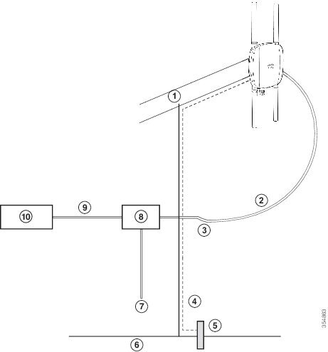
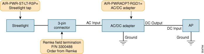
Connecting Streetlight AC Power
The access point can be installed on a streetlight pole and powered from a streetlight outdoor light control using the optional streetlight power tap adapter and AC/DC power adapter, AIR-PWRADPT-RGD1=.
The AC/DC power adapter is used inline from the street light tap to the 1560 DC connector. The AC power tap only can be used with the AC/DC power adapter.
When powering the access point with AC power other than the streetlight power tap adapter, you must ensure that the following conditions are observed:
1.![]() AC power can be conveniently cut from the unit, but not by disconnecting the AC power connector on the unit.
AC power can be conveniently cut from the unit, but not by disconnecting the AC power connector on the unit.
2.![]() You must protect any AC power plugs and AC receptacles from water and other outdoor elements. You can use a UL-listed waterproofing enclosure suitable for covering the AC receptacle and AC power plug that supplies power to the unit as described in Article 406 of the NEC.
You must protect any AC power plugs and AC receptacles from water and other outdoor elements. You can use a UL-listed waterproofing enclosure suitable for covering the AC receptacle and AC power plug that supplies power to the unit as described in Article 406 of the NEC.
3.![]() When you install the access point outdoors or in a wet or damp location, the AC branch circuit that powers the access point should have ground fault protection (GFCI), as required by Article 210 of the National Electrical Code (NEC).
When you install the access point outdoors or in a wet or damp location, the AC branch circuit that powers the access point should have ground fault protection (GFCI), as required by Article 210 of the National Electrical Code (NEC).
Warning![]() A readily accessible two-poled disconnect device must be incorporated in the fixed wiring.
A readily accessible two-poled disconnect device must be incorporated in the fixed wiring.
Statement 1022
Warning![]() Be very careful when connecting the streetlight adapter to Category 3 pole-top power. If you are not careful, you may electrocute yourself or fall. Statement 363
Be very careful when connecting the streetlight adapter to Category 3 pole-top power. If you are not careful, you may electrocute yourself or fall. Statement 363
The schematics of installing the AP on a streetlight pole are given in Figure 2-34 and Figure 2-35. To install an access point on a streetlight pole, follow these steps:
Step 1![]() Turn off the AC power to the streetlight pole.
Turn off the AC power to the streetlight pole.
Step 2![]() Turn off power to the AC power source at the designated circuits.
Turn off power to the AC power source at the designated circuits.
Warning![]() This unit might have more than one power supply connection. All connections must be removed to de-energize the unit. Statement 1028
This unit might have more than one power supply connection. All connections must be removed to de-energize the unit. Statement 1028
Step 3![]() Ensure that the power to the outdoor light control is turned off and then disconnect the outdoor light control from its fixture.
Ensure that the power to the outdoor light control is turned off and then disconnect the outdoor light control from its fixture.
Step 4![]() Connect the streetlight power tap adapter, through a field termination unit, to the access point AC/DC power adapter.
Connect the streetlight power tap adapter, through a field termination unit, to the access point AC/DC power adapter.
Note ●![]() The access point must be mounted within 3 feet (1 m) of the outdoor light control.
The access point must be mounted within 3 feet (1 m) of the outdoor light control.
- The AC/DC power adapter must be grounded. The AC/DC power adapter has an operating range of 100 to 277 VAC 50/60 Hz.
Step 5![]() Ground the access point to the streetlight pole using a 6-AWG ground wire. For more details, see Grounding the Access Point.
Ground the access point to the streetlight pole using a 6-AWG ground wire. For more details, see Grounding the Access Point.
Step 6![]() Plug the streetlight power tap adapter into the outdoor light control fixture.
Plug the streetlight power tap adapter into the outdoor light control fixture.
Step 7![]() Ensure that the antennas are connected to the access point.
Ensure that the antennas are connected to the access point.
Step 8![]() Turn on the power to the outdoor light control fixture at the designated circuits, and thereby, turn on the power to the access point.
Turn on the power to the outdoor light control fixture at the designated circuits, and thereby, turn on the power to the access point.
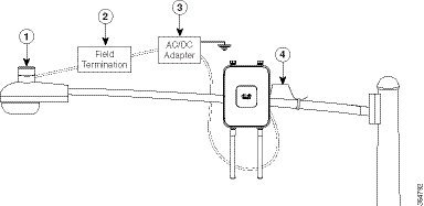
Figure 2-34 Using Streetlight Power
|
|
|
The AC/DC power adapter must be grounded. The AC/DC power adapter has an operating range of 100 to 277 VAC 50/60 Hz. |
|
|
|
|
Figure 2-35 Components of the Streetlight Deployment
Note![]() Deployment of the AP as shown in the streetlight deployment in Figure 2-34 requires an alternate AP mounting kit.
Deployment of the AP as shown in the streetlight deployment in Figure 2-34 requires an alternate AP mounting kit.
Connecting Data Cables
All models of the AP support data connections through the Ethernet port and the Small Form-factor Pluggable (SFP) port. However, both the Ethernet port and the SFP port cannot be used for data at the same time.
If the SFP is detected and active, the Ethernet port is disconnected. If the SFP is not detected, the Ethernet port stays connected
If you are using the SFP port, to delivery data through a fiber-optic cable, then the AP needs to be powered by DC power, power adapter, or by a power injector.
For details on installing Ethernet, see Connecting an Ethernet Cable to the Access Point.
For details on installing a a fiber-optic cable, see Connecting a Fiber-optic Cable to the AP.
Connecting an Ethernet Cable to the Access Point
You need to supply these tools and materials:
- Shielded outdoor-rated Ethernet (CAT5e or better) cable with 0.2 to 0.35 in. (0.51 to 0.89 cm) diameter
- RJ-45 connector and installation tool
- Adjustable Wrench or 28 mm box wrench
- Large Phillips or Flat Blade screwdriver
To connect the shielded Ethernet cable to the access point, follow these steps:
Step 1![]() Disconnect power to the power injector, and ensure all power sources to the access point are turned off.
Disconnect power to the power injector, and ensure all power sources to the access point are turned off.
Warning![]() This unit might have more than one power supply connection. All connections must be removed to de-energize the unit. Statement 1028
This unit might have more than one power supply connection. All connections must be removed to de-energize the unit. Statement 1028
Step 2![]() Ensure a 6 AWG ground wire is connected to the access point (see the “Grounding the Access Point” section).
Ensure a 6 AWG ground wire is connected to the access point (see the “Grounding the Access Point” section).
Step 3![]() Use a large Phillips or Flat Blade screw driver to remove the covering plug from the access point. Do not discard plug and rubber seal unless you are certain that the port will not have to be re-plugged (see Figure 2-36 for the location).
Use a large Phillips or Flat Blade screw driver to remove the covering plug from the access point. Do not discard plug and rubber seal unless you are certain that the port will not have to be re-plugged (see Figure 2-36 for the location).
Figure 2-36 Access Point PoE-In Connector
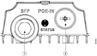
|
|
|
Step 4![]() Loosen the Thread-Lock sealing nut of the cable gland by turning it counter clockwise, but do not remove it (see Figure 2-37).
Loosen the Thread-Lock sealing nut of the cable gland by turning it counter clockwise, but do not remove it (see Figure 2-37).
Note![]() Verify that the cable gland has a rubber seal and ensure that it is not damaged.
Verify that the cable gland has a rubber seal and ensure that it is not damaged.
Warning![]() Failure to install the cable gland and rubber gasket properly will cause the cable grip to leak.
Failure to install the cable gland and rubber gasket properly will cause the cable grip to leak.
|
|
|
||
|
|
|
||
|
|
|
Step 5![]() Insert the unterminated end of the Ethernet cable through the sealing nut end of the cable gland (see Figure 2-37), and pull several inches of cable through the adapter.
Insert the unterminated end of the Ethernet cable through the sealing nut end of the cable gland (see Figure 2-37), and pull several inches of cable through the adapter.
Step 6![]() Install an RJ-45 connector on the unterminated end of the Ethernet cable using your Ethernet cable installation tool.
Install an RJ-45 connector on the unterminated end of the Ethernet cable using your Ethernet cable installation tool.
Warning![]() To reduce the risk of fire, use only No. 26 AWG or larger telecommunication line cord. Statement 1023
To reduce the risk of fire, use only No. 26 AWG or larger telecommunication line cord. Statement 1023
Warning![]() When installing the RJ-45 connector, ensure that cable gland and the rubber gasket are present and installed properly, to avoid water leakage into the enclosure. See Figure 2-37 and Figure 2-38.
When installing the RJ-45 connector, ensure that cable gland and the rubber gasket are present and installed properly, to avoid water leakage into the enclosure. See Figure 2-37 and Figure 2-38.
Step 7![]() Carefully insert the RJ-45 cable connector into the Ethernet port opening on the access point, and connect to the internal Ethernet connector (see Figure 2-38).
Carefully insert the RJ-45 cable connector into the Ethernet port opening on the access point, and connect to the internal Ethernet connector (see Figure 2-38).
Figure 2-38 Inserting RJ-45 Connector into the Ethernet Port Opening in Case
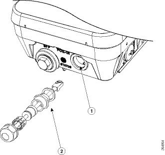
|
|
|
RJ-45 connector, on shielded outdoor-rated Ethernet (CAT5e or better) cable (with an exploded view of the cable gland, on the Ethernet cable). |
Step 8![]() Slide the cable gland with the rubber seal towards the access point, and screw the threaded end of the body into the access point, and hand-tighten.
Slide the cable gland with the rubber seal towards the access point, and screw the threaded end of the body into the access point, and hand-tighten.
Step 9![]() Use an adjustable wrench or a 28-mm wrench to tighten the threaded end of the body into the enclosure. Tighten to 15 lb-in.
Use an adjustable wrench or a 28-mm wrench to tighten the threaded end of the body into the enclosure. Tighten to 15 lb-in.
Step 10![]() Use an adjustable wrench and tighten the thread-lock seal nut to 15 lb-in.
Use an adjustable wrench and tighten the thread-lock seal nut to 15 lb-in.
Step 11![]() Ensure that the antennas are connected to the access point before you apply power to the access point.
Ensure that the antennas are connected to the access point before you apply power to the access point.
Step 12![]() Route your Ethernet cable, and cut off any excess cable.
Route your Ethernet cable, and cut off any excess cable.
Step 13![]() Install an RJ-45 connector on the unterminated cable end, and insert it into the power injector.
Install an RJ-45 connector on the unterminated cable end, and insert it into the power injector.
Step 14![]() Turn on the power to the power injector.
Turn on the power to the power injector.
Connecting a Fiber-optic Cable to the AP
The Cisco supplied fiber-optic kit enables the access point to support fiber-optic network connections.
Your require the following materials for connecting the fiber-optic cable to the AP:
- Small form-factor pluggable (SFP) transceiver module
- SFP module adapter
- SC or Duplex LC fiber-optic cables. The outer diameter of the fiber optic cable should be 0.24-0.47 inches (6-12 mm).
- Cable gland. The cable gland cannot hold a cable with diameter more than 0.47” (12 mm).
- Adjustable wrench
You can connect the fiber-optic networking cable to the SFP port (labeled '4' on the base of the AP). The small form-factor pluggable (SFP) transceiver module is used to connect the cable to the SFP port. To install the SFP transceiver module and the cable, follow this procedure:
Step 1![]() Ensure that all power sources have been disconnected from the access point.
Ensure that all power sources have been disconnected from the access point.
Step 2![]() Remove the covering plug from the SFP port by following the guidelines given in this step.
Remove the covering plug from the SFP port by following the guidelines given in this step.
The SFP port covering plug is designed to be removed only once, and then be replaced with the SFP adapter. The plug does not have a rubber O-ring, but is fixed in place using a thread seal tape on the threads during manufacturing. While removing the plug, you need to ensure that its hex bolt-head does not get stripped. For this:
a.![]() Place the AP on it's back (resting on the heat fins) on a solid, but padded surface, to avoid scratching the paint.
Place the AP on it's back (resting on the heat fins) on a solid, but padded surface, to avoid scratching the paint.
b.![]() Pressing down with your hand on the face of the AP and holding the AP firmly in place, proceed to the next step.
Pressing down with your hand on the face of the AP and holding the AP firmly in place, proceed to the next step.
c.![]() Use a 5/8” (16 mm) 6-point socket wrench to loosen the hex bolt-head SFP port plug. Firmly and carefully, turn the socket wrench counter-clockwise to loosen the plug. This requires a torque of 25 ft-lb (34 Nm).
Use a 5/8” (16 mm) 6-point socket wrench to loosen the hex bolt-head SFP port plug. Firmly and carefully, turn the socket wrench counter-clockwise to loosen the plug. This requires a torque of 25 ft-lb (34 Nm).
Though not ideal, a 5/8” (16 mm) 12-point socket wrench can be used too. A crescent wrench is to be used only if the socket wrenches are not available. Do not use a pipe or monkey wrench for this task, as it will strip the hex bolt-head.
Step 3![]() Insert the SFP module into the SFP port, and ensure that it latches properly.
Insert the SFP module into the SFP port, and ensure that it latches properly.
Step 4![]() Loosen the cable gland’s nut (round end of the cable gland) by turning counterclockwise, but do not remove.
Loosen the cable gland’s nut (round end of the cable gland) by turning counterclockwise, but do not remove.
Step 5![]() Thread the fiber optic cable, from its unterminated end, into the cable gland. See Figure 2-39 and Figure 2-40.
Thread the fiber optic cable, from its unterminated end, into the cable gland. See Figure 2-39 and Figure 2-40.
Thread the cable through the gland all the way till the gland is near the SC or LC optic fiber connectors. The cable gland’s nut must remain loose at this time.
Note![]() The SC or LC optic fiber connectors are too big to pass through the cable gland. That is the reason why you need to thread the cable through the gland from the unterminated end (even if the cable is quite long).
The SC or LC optic fiber connectors are too big to pass through the cable gland. That is the reason why you need to thread the cable through the gland from the unterminated end (even if the cable is quite long).
Step 6![]() Insert the SC or LC optic fiber connector-end of the cable, into the SFP module adapter. Do not attach the cable gland to the adapter yet. See Figure 2-41.
Insert the SC or LC optic fiber connector-end of the cable, into the SFP module adapter. Do not attach the cable gland to the adapter yet. See Figure 2-41.
Step 7![]() Insert the SC or LC optic fiber connector into the SFP module and ensure that it latches into place. See Figure 2-41.
Insert the SC or LC optic fiber connector into the SFP module and ensure that it latches into place. See Figure 2-41.
Step 8![]() Add sealant or tape around the adapter's pipe thread, and then it screw into the AP chassis.
Add sealant or tape around the adapter's pipe thread, and then it screw into the AP chassis.
Step 9![]() Keeping the cable gland nut loose, carefully screw the threaded end of the cable gland into the SFP module adapter and hand-tighten. Use an adjustable wrench to tighten the threaded end of the cable gland to 6-7 lb.ft (8.1 to 9.5 Nm).
Keeping the cable gland nut loose, carefully screw the threaded end of the cable gland into the SFP module adapter and hand-tighten. Use an adjustable wrench to tighten the threaded end of the cable gland to 6-7 lb.ft (8.1 to 9.5 Nm).
Step 10![]() Tighten the cable gland nut until it is properly fastened around the fiber optic cable. Use an adjustable or open-end wrench to tighten to 2.7 to 3.2 lb.ft (3.66 to 4.34 Nm).
Tighten the cable gland nut until it is properly fastened around the fiber optic cable. Use an adjustable or open-end wrench to tighten to 2.7 to 3.2 lb.ft (3.66 to 4.34 Nm).
Figure 2-39 SC Fiber-optic cable
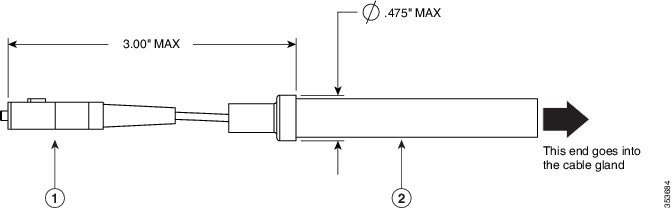
|
|
|
Figure 2-40 Duplex LC Fiber Optic Cable
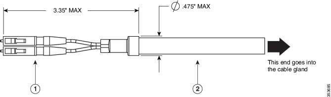
|
|
|
Figure 2-41 Exploded View of Connecting Fiber-Optic Cable to AP
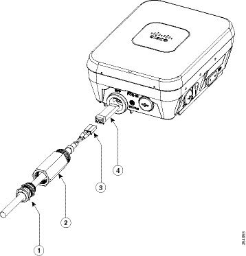
|
|
|
||
|
|
|
Figure 2-42 Fiber-optic Cable Successfully Connected to AP
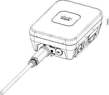
Configuring the Access Point
When you power up an AP that is not connected to a wired Ethernet, fiber-optic, or cable network to the controller, the access point uses the Cisco Adaptive Wireless Path Protocol (AWPP) to bind to another mesh access point with the best path to a root access point (RAP) connected to the wired network to a controller. The access point sends a discovery request when powered up. If you have configured the access point in the controller correctly, the controller sends back a discovery response to the access point. When that happens, the access point sends out a join request to the controller, and the controller responds with a join confirmation response. Then the access point establishes a Control And Provisioning of Wireless Access Points (CAPWAP) connection to the controller and gets the shared secret configured on the controller.
For information on configuring the access point, refer the following documents for the software release you are using:
 Feedback