- Unpacking the Access Point
- Mounting the Access Point
- Wall Mounting the Access Point with AIR-ACC1530-PMK1=
- Pole Mounting the Access Point with AIR-ACC1530-PMK1=
- Wall Mounting the AP using AIR-ACC1530-PMK2= Pivoting Mounting Kit
- Pole Mounting the AP using AIR-ACC1530-PMK2= Pivoting Mounting Kit
- Horizontally Mounting the Access Point using AIR-ACC1530-PMK2=
- Installing AP Cover AIR-ACC1540-CVR=
- Grounding the Access Point
- Powering the Access Point
- Configuring the Access Point
Installing the Access Point
This chapter describes how to install the 1540 series access point and accessories. It contains the following sections:
- Unpacking the Access Point
- Mounting the Access Point
- Installing AP Cover AIR-ACC1540-CVR=
- Grounding the Access Point
- Powering the Access Point
- Configuring the Access Point

Warning![]() Read the installation instructions before connecting the system to the power source. Statement 1004
Read the installation instructions before connecting the system to the power source. Statement 1004
Warning![]() Installation of the equipment must comply with local and national electrical codes. Statement 1074
Installation of the equipment must comply with local and national electrical codes. Statement 1074
Warning![]() This unit is intended for installation in restricted access areas. A restricted access area can be accessed only through the use of a special tool, lock and key, or other means of security.
This unit is intended for installation in restricted access areas. A restricted access area can be accessed only through the use of a special tool, lock and key, or other means of security.
Statement 1017
Warning![]() Ultimate disposal of this product should be handled according to all national laws and regulations. Statement 1040
Ultimate disposal of this product should be handled according to all national laws and regulations. Statement 1040
Warning![]() Do not work on the system or connect or disconnect cables during periods of lightning activity. Statement 1001
Do not work on the system or connect or disconnect cables during periods of lightning activity. Statement 1001
Unpacking the Access Point
To unpack the access point, follow these steps:
Step 1![]() Open the shipping container and carefully remove the contents.
Open the shipping container and carefully remove the contents.
Step 2![]() Return all packing materials to the shipping container, and save it.
Return all packing materials to the shipping container, and save it.
Step 3![]() Ensure that all items listed in “Package Contents” are included in the shipment. If any item is damaged or missing, notify your authorized Cisco sales representative.
Ensure that all items listed in “Package Contents” are included in the shipment. If any item is damaged or missing, notify your authorized Cisco sales representative.
Your shipment may also contain additional equipment as per your order, as listed in Optional Tools and Hardware From Cisco.
For additional hardware that is required for installation, see Additional Tools and Hardware Required for Installation.
Package Contents
Each access point package contains the following items:
- One 1540 series access point
- Ground lug and screws with lock washers
- Ethernet field terminator
- Plastic dust cap (installed on console port)
- Weatherization tape and anti-corrosion sealant
- Cisco product documentation and pointer card
- Wall/pole mount bracket kit (AIR-ACC1530-PMK1), for an additional charge, only if selected when you ordered the access point
Optional Tools and Hardware From Cisco
Depending on what you ordered, the following optional equipment may be part of your shipment:
- Power injector AIR-PWRINJ6=
- Power injector AIR-PWRINJ5=
- AP cover / Solar Shield for 1540, AIR-ACC1540-CVR=
- AIR-ACC1540-KIT1= spare parts kit which includes:
Additional Tools and Hardware Required for Installation
You need to independently procure the following tools and materials which maybe required during various stages of installing the AP:
- 10 mm open end or box wrench
- Ground lug crimping tool (Panduit CT-720 with CD-720-1 die)
- 6 AWG copper ground wire
- Medium flat or Phillips screw driver (for the solar cover)
- Shielded outdoor-rated Ethernet (CAT5e or better) cable of 0.20 to 0.35 inches (0.51 to 0.89 cm) diameter.
- Ethernet RJ45 connector and installation tool
- Ground rod as required by local regulations
Pre-Installation Checks and Installation Guidelines
As the access point is a radio device, it is susceptible to common causes of interference that can reduce throughput and range. Follow these basic guidelines to ensure the best possible performance:
- Thoroughly review the information provided in Safety Guidelines and Warnings.
- For information on planning and initially configuring your Cisco Mesh network, refer to the Cisco Wireless Access Points, Design and Deployment Guide, Release 7.3.
- Review the FCC guidelines for installing and operating outdoor wireless LAN devices at:
http://www.cisco.com/c/en/us/products/collateral/routers/3200-series-rugged-integrated-services-routers-isr/data_sheet_c78-647116.html
- Install the access point in an area where structures, trees, or hills do not obstruct radio signals to and from the access point.
- We recommend installing the access points no higher than 40 feet to allow support for wireless clients on the ground. Best throughput is achieved when all the access points are mounted at the same height.
- The console port is shipped with a cap on it. Inspect the cap at the time of installation. Every time the cap is removed or replaced, properly tighten it. If you do not tighten the cap properly, it will not meet IP67 criteria, and may lead to water leaking into the unit.

Note![]() To calculate path loss and to determine how far apart to install access points, consult an RF planning expert.
To calculate path loss and to determine how far apart to install access points, consult an RF planning expert.
Before you begin the installation process, ensure the following:
- Perform a site survey. See the “Performing Site Surveys” section.
- Your network infrastructure devices must be operational and properly configured.
- Your controllers are connected to switch trunk ports.
- Your switch is configured with untagged access ports for connecting your access points.
- A DHCP server with Option 43 configured is reachable by your access points, or manually configure the controller information in the access point. For information on configuring the DHCP Option 43, visit the following URL:
http://www.cisco.com/c/en/us/support/docs/wireless-mobility/wireless-lan-wlan/97066-dhcp-option-43-00.html
- Become familiar with the access point installation components. See the “Typical Access Point Installation Components” section.
Typical Access Point Installation Components
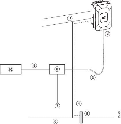
The access point is designed to be installed in an outdoor environment, such as the exterior roof overhang of a tall building or a streetlight pole. Carefully review Figure 2-1 to become familiar with the system components, connectors, indicators, cables, system interconnection, and grounding.
Figure 2-1 Components in a Typical Access Point Installation
|
|
|
||
|
|
Shielded outdoor-rated Ethernet |
|
|
|
|
|
||
|
|
|
||
|
|
|
|
|
Mounting the Access Point
This section provides instructions for installing your access points. Personnel installing the access point must have a good understanding of wireless access points, bridging techniques, and grounding methods.
The 1540 Series access points can be wall or pole mounted. The 1540 uses the same mounting brackets as the 1530 and 1560 Series access points, and are listed below.
|
|
|
|---|---|
Fixed mounting kit for vertical mounting on wall and pole. See:
Mount the access point in such a way that there are no obstructions to accessing the console port. |
|
Pivoted mounting kit for both vertical and horizontal mounting, on wall |
Note![]() When the AP is vertically mounted, the AP is oriented with the Console and PoE ports, and the status LED, facing downward.
When the AP is vertically mounted, the AP is oriented with the Console and PoE ports, and the status LED, facing downward.
Wall Mounting the Access Point with AIR-ACC1530-PMK1=
The AIR-ACC1530-PMK1= mounting kit contains a mounting bracket for wall mounting or pole mounting.
You can use the mounting bracket as a template to mark the positions of the mounting holes for your installation, install the mounting bracket, and then attach the access point to the bracket.
Table 2-1 lists the materials needed for this installation.
|
|
|
|---|---|
Crimping tool for ground lug, Panduit CT-720 with CD-720-1 die (http://www.panduit.com) |
|

To mount the access point vertically on a wall, follow these instructions:
Step 1![]() Use the mounting bracket as a template to mark four screw hole locations on the mounting wall. The mounting bracket screw hole locations are shown in Figure 2-2. The dimensions of the mounting bracket is shown in Figure 2-3.
Use the mounting bracket as a template to mark four screw hole locations on the mounting wall. The mounting bracket screw hole locations are shown in Figure 2-2. The dimensions of the mounting bracket is shown in Figure 2-3.
Step 2![]() Use four screws and, if required, wall anchors to attach the mounting plate to the mounting surface. These screws and anchors are to be sourced independently.
Use four screws and, if required, wall anchors to attach the mounting plate to the mounting surface. These screws and anchors are to be sourced independently.
Note![]() You can use an exterior-grade plywood backboard to mount the access point to stucco, cement, or dry wall.
You can use an exterior-grade plywood backboard to mount the access point to stucco, cement, or dry wall.
Note![]() The mounting wall, attaching screws, and wall anchors must be able to support a 50 lb (22.7 kg) static weight.
The mounting wall, attaching screws, and wall anchors must be able to support a 50 lb (22.7 kg) static weight.
Step 3![]() Screw an M6 x12 mm bolt into each of the four support bolt holes on the back of the access point. Do not screw the bolt all the way in, but leave a gap of approximately 0.13 inch (3.3 mm).
Screw an M6 x12 mm bolt into each of the four support bolt holes on the back of the access point. Do not screw the bolt all the way in, but leave a gap of approximately 0.13 inch (3.3 mm).
Step 4![]() Position the access point against mounting bracket such that the four support bolts on the back of the AP, slot into the keyhole slots on the mounting bracket.
Position the access point against mounting bracket such that the four support bolts on the back of the AP, slot into the keyhole slots on the mounting bracket.
Step 5![]() Slide the access point down to seat it securely in the keyhole slots on the mounting bracket.
Slide the access point down to seat it securely in the keyhole slots on the mounting bracket.
Note![]() The access point should be mounted with the status LED on the base facing downwards.
The access point should be mounted with the status LED on the base facing downwards.
Step 6![]() Using a 10mm wrench, tighten the four bolts that connect the access point to the bracket, to a torque of 40 lbf-in.
Using a 10mm wrench, tighten the four bolts that connect the access point to the bracket, to a torque of 40 lbf-in.
Step 7![]() Proceed with connecting the data cables, grounding the access point, powering and configuring the access point.
Proceed with connecting the data cables, grounding the access point, powering and configuring the access point.
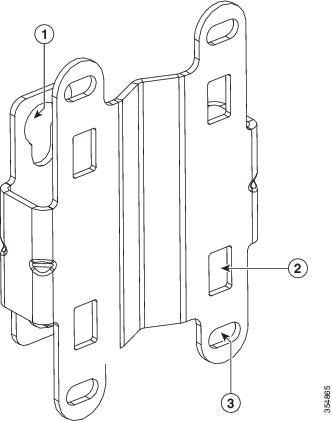
Figure 2-2 Mounting Bracket for Wall and Pole Mounting
|
|
|
Bracket mount holes for fastening bracket to the wall. You can use bolts of up to 1/4 inch or 6 mm in diameter. |
|
|
|
One of four slots for steel band clamps, used for pole mounting only. |
|
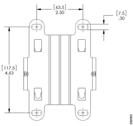
Figure 2-3 Mounting Bracket Dimensions in inches [and millimeters]
Pole Mounting the Access Point with AIR-ACC1530-PMK1=
The AIR-ACC1530-PMK1= mounting kit contains a mounting bracket that can be used for both wall mounting and pole mounting. This kit can be used to install the access point on a pole, mast or streetlight. It supports metal, wood or fiberglass poles from 2 to 8 inches in diameter.
Table 2-2 Materials Needed to Mount the AP on a Vertical Pole
To mount the access point onto a vertical pole, follow these steps:
Step 1![]() Select a mounting location on the pole to mount the access point. You can attach the access point to a pole having a diameter of 2 to 8 inches (5.1 to 20.1 cm).
Select a mounting location on the pole to mount the access point. You can attach the access point to a pole having a diameter of 2 to 8 inches (5.1 to 20.1 cm).
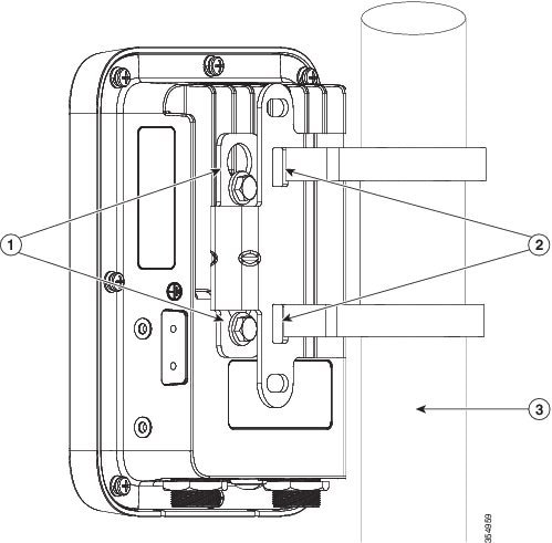
Step 2![]() Hold the bracket up against the pole, and slide the two band straps through the top and bottom sets of mounting slots on the mounting bracket (see Figure 2-4).
Hold the bracket up against the pole, and slide the two band straps through the top and bottom sets of mounting slots on the mounting bracket (see Figure 2-4).
Step 3![]() Wrap the band straps around the pole, lock them, and then lightly tighten the clamps using a wrench. Only tighten them enough to keep the bracket from sliding down the pole
Wrap the band straps around the pole, lock them, and then lightly tighten the clamps using a wrench. Only tighten them enough to keep the bracket from sliding down the pole
Step 4![]() Screw an M6 bolt into each of the four bolt holes on the back side of the access point. Do not screw the bolt in all the way. Leave a gap of about 0.13-inch (3.3 mm).
Screw an M6 bolt into each of the four bolt holes on the back side of the access point. Do not screw the bolt in all the way. Leave a gap of about 0.13-inch (3.3 mm).
Step 5![]() Position the four bolts on the access point into the bracket keyhole slots. Check to be sure that the access point is properly seated in the slots (see Figure 2-4).
Position the four bolts on the access point into the bracket keyhole slots. Check to be sure that the access point is properly seated in the slots (see Figure 2-4).
Note![]() The access point should be mounted with the status LED on the base facing downwards.
The access point should be mounted with the status LED on the base facing downwards.
Step 6![]() Using a 10 mm wrench, tighten the four bolts that connect the access point to the bracket to a torque of 40 lbf-in.
Using a 10 mm wrench, tighten the four bolts that connect the access point to the bracket to a torque of 40 lbf-in.
Step 7![]() Locate the access point to the final position. Tighten the band clamps with the wrench so that the access point does not slide on the pole. Ensure that the clamps are tight enough to not let the AP move.
Locate the access point to the final position. Tighten the band clamps with the wrench so that the access point does not slide on the pole. Ensure that the clamps are tight enough to not let the AP move.
Step 8![]() Proceed with connecting the data cables, grounding the access point, powering and configuring the access point.
Proceed with connecting the data cables, grounding the access point, powering and configuring the access point.
Figure 2-4 AP Mounted on a Pole
Wall Mounting the AP using AIR-ACC1530-PMK2= Pivoting Mounting Kit
The optional pivoting mounting kit AIR-ACC1530-PMK2= contains a pivoting mounting bracket for both wall and pole mounting. This kit allows for adjusting the position of the AP by pivoting the AP along its vertical plane.
Table 2-3 Materials for Mounting on Wall with Pivoting Mounting Kit
To mount the access point vertically on a wall, follow these instructions:
Step 1![]() Disassemble the pivot kit, if not already disassembled. See Figure 2-5.
Disassemble the pivot kit, if not already disassembled. See Figure 2-5.
Step 2![]() Use the wall-plate end of the mounting bracket as a template to mark four screw hole locations on the mounting surface. See Figure 2-5 for the mounting bracket screw hole locations (screw holes of maximum 6 mm in size).
Use the wall-plate end of the mounting bracket as a template to mark four screw hole locations on the mounting surface. See Figure 2-5 for the mounting bracket screw hole locations (screw holes of maximum 6 mm in size).
See Figure 2-6 for the dimensions of the pivoting mounting bracket.
Step 3![]() Use four screws and, if required, wall anchors to attach the wall-plate end of the mounting bracket to the mounting surface. These screws and anchors are to be sourced independently.
Use four screws and, if required, wall anchors to attach the wall-plate end of the mounting bracket to the mounting surface. These screws and anchors are to be sourced independently.
Note![]() You can use an exterior-grade plywood backboard to mount the access point to stucco, cement, or drywall.
You can use an exterior-grade plywood backboard to mount the access point to stucco, cement, or drywall.
Note![]() The mounting wall, attaching screws, and wall anchors must be able to support a 50-lb (22.7 kg) static weight.
The mounting wall, attaching screws, and wall anchors must be able to support a 50-lb (22.7 kg) static weight.
Step 4![]() Align the AP-plate end of the bracket with the screw holes in the back of the access point.
Align the AP-plate end of the bracket with the screw holes in the back of the access point.
Step 5![]() Fasten the bracket plate to the AP by using four M6 x12 mm bolts and a 10 mm box or socket wrench. Torque the bolts to 40 lbf-in.
Fasten the bracket plate to the AP by using four M6 x12 mm bolts and a 10 mm box or socket wrench. Torque the bolts to 40 lbf-in.
Step 6![]() Using the 90.0 mm M8 long screw and the hardware supplied with the pivoting bracket, bolt the AP and bracket plate, to the wall plate mounted on the wall. See Figure 2-5 for this assembly. Do not fully tighten the assembly.
Using the 90.0 mm M8 long screw and the hardware supplied with the pivoting bracket, bolt the AP and bracket plate, to the wall plate mounted on the wall. See Figure 2-5 for this assembly. Do not fully tighten the assembly.
Note![]() The access point should be mounted with the status LED on the base facing downwards.
The access point should be mounted with the status LED on the base facing downwards.
Step 7![]() Pivot the AP as required, and then fully tighten the 90.0 mm M8 long screw using a 13 mm wrench.
Pivot the AP as required, and then fully tighten the 90.0 mm M8 long screw using a 13 mm wrench.
Step 8![]() Proceed with installing antennas (only for external antenna models), connecting the data cables, grounding the access point, powering and configuring the access point.
Proceed with installing antennas (only for external antenna models), connecting the data cables, grounding the access point, powering and configuring the access point.
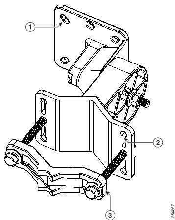
Figure 2-5 Pivoting Mounting Bracket
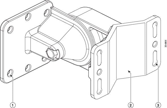
Figure 2-6 Pivoting Mounting Bracket Dimensions
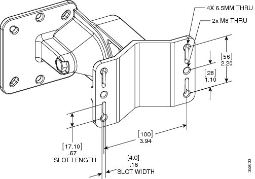
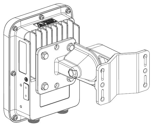
Figure 2-7 Visualization of AP Fastened to the Pivoting Mounting Kit
Pole Mounting the AP using AIR-ACC1530-PMK2= Pivoting Mounting Kit
The optional pivoting mounting kit AIR-ACC1530-PMK2= contains a pivoting mounting bracket for both wall and pole mounting. This kit can be used to install the access point on a pole, mast, or streetlight. It supports metal, wood or fiberglass poles from 2 to 8 inches in diameter.
The AIR-ACC1530-PMK2= pivoting mounting kit allows for adjusting the position of the AP by pivoting the AP along its vertical plane.
To mount the access point on a pole, follow these steps:
Step 1![]() Select a mounting location on the pole to mount the access point. You can attach the access point to any pole with a diameter from 2 to 8 inches (5.1 to 40.6 cm).
Select a mounting location on the pole to mount the access point. You can attach the access point to any pole with a diameter from 2 to 8 inches (5.1 to 40.6 cm).
Note![]() If you will be using a streetlight power tap adapter, position the access point within 3 ft (1 m) of the outdoor light control.
If you will be using a streetlight power tap adapter, position the access point within 3 ft (1 m) of the outdoor light control.
Step 2![]() Disassemble the pivot kit, if not already disassembled. See Figure 2-8.
Disassemble the pivot kit, if not already disassembled. See Figure 2-8.
Step 3![]() Fasten the pivot bracket base plate to the pole using either one set of the adjustable band clamps or the screw clamp (the screw clamp can be used only on poles that are 2-3 inches (50-76 mm) in diameter).
Fasten the pivot bracket base plate to the pole using either one set of the adjustable band clamps or the screw clamp (the screw clamp can be used only on poles that are 2-3 inches (50-76 mm) in diameter).
Step 4![]() Position the pivot bracket base plate and clamp(s) on the pole. Tighten only enough to hold the bracket base plate in place, so as to prevent it from sliding along the pole but still pivot on the pole. Fully tighten only after the access point is mounted and positioned.
Position the pivot bracket base plate and clamp(s) on the pole. Tighten only enough to hold the bracket base plate in place, so as to prevent it from sliding along the pole but still pivot on the pole. Fully tighten only after the access point is mounted and positioned.
Step 5![]() Align the AP-plate end of the bracket with the screw holes in the back of the access point.
Align the AP-plate end of the bracket with the screw holes in the back of the access point.
Step 6![]() Fasten the bracket plate to the AP by using four M6 x12 mm bolts and a 10 mm box or socket wrench. Torque the bolts to 40 lbf-in (4.5Nm).
Fasten the bracket plate to the AP by using four M6 x12 mm bolts and a 10 mm box or socket wrench. Torque the bolts to 40 lbf-in (4.5Nm).
Step 7![]() Using the 90.0 mm M8 long screw and the hardware supplied with the pivoting bracket, bolt the AP and bracket plate, to the base plate mounted on the pole. See Figure 2-7. Do not fully tighten the assembly.
Using the 90.0 mm M8 long screw and the hardware supplied with the pivoting bracket, bolt the AP and bracket plate, to the base plate mounted on the pole. See Figure 2-7. Do not fully tighten the assembly.
Note![]() The access point should be mounted with the status LED on the base facing downwards.
The access point should be mounted with the status LED on the base facing downwards.
Step 8![]() Pivot and position the AP as required, and then fully tighten the 90.0 mm M8 long screw using a 13 mm wrench, and then tighten the clamps on the pole.
Pivot and position the AP as required, and then fully tighten the 90.0 mm M8 long screw using a 13 mm wrench, and then tighten the clamps on the pole.
Note![]() Use caution when tightening the 80 mm bolts on the pole-mount screw clamp. See Figure 2-8. Ensure the clamp face remains parallel to the bracket base plate while tightening the bolts. Torque the M8 x 80 mm bolts to 52-61 lbf-in (5.9-6.9 Nm).
Use caution when tightening the 80 mm bolts on the pole-mount screw clamp. See Figure 2-8. Ensure the clamp face remains parallel to the bracket base plate while tightening the bolts. Torque the M8 x 80 mm bolts to 52-61 lbf-in (5.9-6.9 Nm).
Step 9![]() Proceed with installing antennas (only for external antenna models), connecting the data cables, grounding the access point, powering and configuring the access point.
Proceed with installing antennas (only for external antenna models), connecting the data cables, grounding the access point, powering and configuring the access point.
Figure 2-8 Exploded View of the Pivoting Mounting Kit
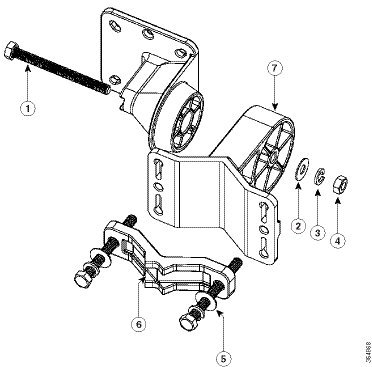
|
|
|
80.0 mm M8 screw with washer and spring washer, for fastening the pole-mount screw clamp to the pivoting bracket base plate. |
|
|
|
|||
|
|
|
||
|
|
|
Figure 2-9 Pivoting Mounting Kit with Pole Mount Clamp
Horizontally Mounting the Access Point using AIR-ACC1530-PMK2=
The AIR-ACC1530-PMK2= pivoting pole mount kit contains a horizontal mount plate that allows the AP to be mounted horizontally, as shown in Figure 2-11. The horizontal mounting provides better omni antenna coverage.
To mount the AP horizontally using AIR-ACC1530-PMK2=, follow these steps:
Step 1![]() Mount the pivot bracket to a wall or a pole as shown in the previous procedures. However, stop before mounting the pivot bracket plate directly to the access point.
Mount the pivot bracket to a wall or a pole as shown in the previous procedures. However, stop before mounting the pivot bracket plate directly to the access point.
Step 2![]() Using four M6 x 12 mm bolts, fasten the horizontal adapter plate to the pivot bracket plate.
Using four M6 x 12 mm bolts, fasten the horizontal adapter plate to the pivot bracket plate.
Step 3![]() Using the remaining four M6 x 12 mm bolts, mount the other side of the horizontal mounting plate to the AP. See Figure 2-10 for the exploded view.
Using the remaining four M6 x 12 mm bolts, mount the other side of the horizontal mounting plate to the AP. See Figure 2-10 for the exploded view.
Step 4![]() Using a 10 mm wrench or socket, tighten all M6 bolts to 40 lbf-in (4.5 Nm).
Using a 10 mm wrench or socket, tighten all M6 bolts to 40 lbf-in (4.5 Nm).
Step 5![]() Position and orient the access point as needed and tighten the mount kit bolts using a 13 mm wrench or socket. See Figure 2-11.
Position and orient the access point as needed and tighten the mount kit bolts using a 13 mm wrench or socket. See Figure 2-11.
Figure 2-10 Exploded View of the Pivot Bracket Parts with Horizontal Mount Plate
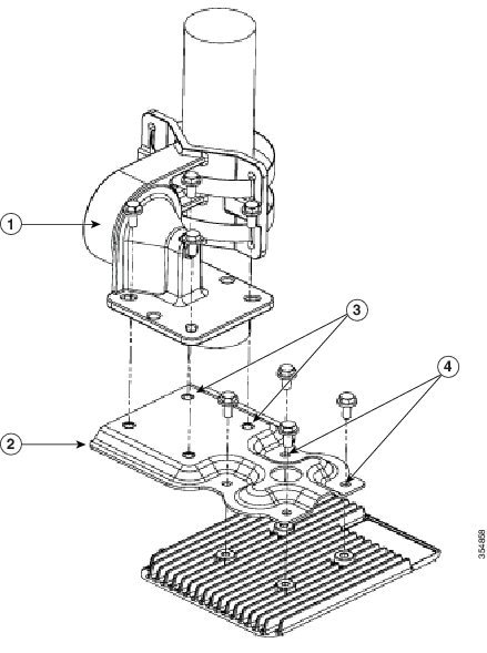
|
|
|
Two out of four screw holes for mounting the horizontal mounting plate to the pivoting bracket. |
|
|
|
|
Two out of four screw holes for mounting the access point to the horizontal mounting plate. |
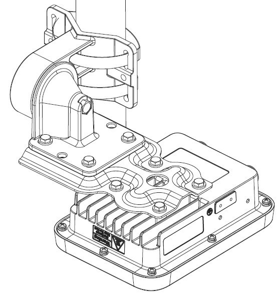
Figure 2-11 Access Point Horizontally Mounted using the Optional Horizontal Mount Plate
Installing AP Cover AIR-ACC1540-CVR=
You can install a cover AIR-ACC1540-CVR=, which also acts as a a solar shield. The cover can be installed before or after all connections are made.
Step 1![]() Position and slide the cover over the AP as shown in Figure 2-12.
Position and slide the cover over the AP as shown in Figure 2-12.
Step 2![]() Align the two holes on each side of the cover with the screw holes on corresponding side of the AP.
Align the two holes on each side of the cover with the screw holes on corresponding side of the AP.
Step 3![]() Insert and fasten #6-32 screws through the screw holes in the cover, into the AP. Tighten the screws to 10 lb-in.
Insert and fasten #6-32 screws through the screw holes in the cover, into the AP. Tighten the screws to 10 lb-in.
Figure 2-12 Installing the Cover on the AP
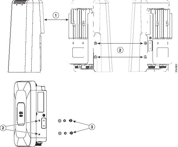
|
|
|
||
|
|
Four screw holes for fastening the solar cover, with two on each side of the AP |
|
Grounding the Access Point
Warning![]() Hazardous network voltages are present in WAN ports regardless of whether power to the unit is OFF or ON. To avoid electric shock, use caution when working near WAN ports. When detaching cables, detach the end away from the unit first. Statement 1026
Hazardous network voltages are present in WAN ports regardless of whether power to the unit is OFF or ON. To avoid electric shock, use caution when working near WAN ports. When detaching cables, detach the end away from the unit first. Statement 1026
The access point must be grounded before connecting power.
In all outdoor installations, you must follow these instructions to properly ground the case:
Step 1![]() If you are using insulated 6 AWG copper ground wire, strip the insulation as required for the grounding lug.
If you are using insulated 6 AWG copper ground wire, strip the insulation as required for the grounding lug.
Step 2![]() Use the appropriate crimping tool to crimp the bare 6 AWG copper ground wire to the supplied grounding lug.
Use the appropriate crimping tool to crimp the bare 6 AWG copper ground wire to the supplied grounding lug.
Note![]() The grounding lug and hardware used must comply with local and national electrical codes.
The grounding lug and hardware used must comply with local and national electrical codes.
Step 3![]() Open the anti-corrosion sealant (supplied), and apply a liberal amount over the metal surface, called the Ground Pad, where the ground strap screw holes are located (see Figure 1-3).
Open the anti-corrosion sealant (supplied), and apply a liberal amount over the metal surface, called the Ground Pad, where the ground strap screw holes are located (see Figure 1-3).
Step 4![]() Connect the grounding lug to the access point grounding screw holes (see Figure 1-3) using the supplied two Phillips head screws (M4 x10 mm) with lock washers. Tighten the grounding screw to 22 to 24 lb-in (2.49 to 2.71 Nm).
Connect the grounding lug to the access point grounding screw holes (see Figure 1-3) using the supplied two Phillips head screws (M4 x10 mm) with lock washers. Tighten the grounding screw to 22 to 24 lb-in (2.49 to 2.71 Nm).
Step 5![]() If necessary, strip the other end of the ground wire and connect it to a reliable earth ground, such as a grounding rod or an appropriate grounding point on a metal streetlight pole that is grounded.
If necessary, strip the other end of the ground wire and connect it to a reliable earth ground, such as a grounding rod or an appropriate grounding point on a metal streetlight pole that is grounded.
Powering the Access Point
The 1540 series access points can be powered only through Power-over-Ethernet (PoE), using 802.3af or 802.3at power, or UPoE, from in-line power injector or a suitably powered switch port. Power for full operation is provided by 802.3af (or higher), and operates at 2x2:2 for both 2.4 GHz and 5 GHz radios.
The 1540 series access point supports the following power injectors:
- AIR-PWRINJ5 (provides 802.3af power)
- AIR-PWRINJ6 (provides 802.3at power). This power injector can only be used in an indoor environment. Therefore the cable from the injector must travel from the indoor location to the access point mounted outdoor.
- AIR-PWRINJ-60RGD1
- AIR-PWRINJ-60RGD2
- PoE supply rated at 48-56V DC, minimum 350 mA
- Cisco UPoE
Connecting a Power Injector
When your access point is powered by a power injector, follow these steps to complete the installation:
Step 1![]() Before applying PoE to the access point, ensure that the access point is grounded (see the “Grounding the Access Point” section).
Before applying PoE to the access point, ensure that the access point is grounded (see the “Grounding the Access Point” section).
Step 2![]() See the “Typical Access Point Installation Components” section, to identify the components needed for the installation.
See the “Typical Access Point Installation Components” section, to identify the components needed for the installation.
Step 3![]() Connect a CAT5e or better Ethernet cable from your wired LAN network to the power injector.
Connect a CAT5e or better Ethernet cable from your wired LAN network to the power injector.
Note![]() The installer is responsible for ensuring that powering the access point from this type of power injector is allowed by local and/or national safety and telecommunications equipment standards.
The installer is responsible for ensuring that powering the access point from this type of power injector is allowed by local and/or national safety and telecommunications equipment standards.

Tip To forward bridge traffic, add a switch between the power injector and controller. Refer to the Cisco Wireless Mesh Access Points, Design and Deployment Guide, Release 7.0 for more information.
Step 4![]() Ensure that the access point is grounded before you apply power to the access point.
Ensure that the access point is grounded before you apply power to the access point.
Step 5![]() Connect a shielded outdoor-rated Ethernet (CAT5e or better) cable between the power injector and the PoE-in connector of the access point.
Connect a shielded outdoor-rated Ethernet (CAT5e or better) cable between the power injector and the PoE-in connector of the access point.
Step 6![]() Connect the Ethernet cable to the access point PoE-In port. See “Connecting an Ethernet Cable to the Access Point” section.
Connect the Ethernet cable to the access point PoE-In port. See “Connecting an Ethernet Cable to the Access Point” section.
For details on installing Ethernet, see Connecting an Ethernet Cable to the Access Point.
Connecting an Ethernet Cable to the Access Point
You need to supply these tools and materials:
- Shielded outdoor-rated Ethernet (CAT5e or better) cable with a diameter of 0.2 to 0.35 inch (0.51 to 0.89 cm)
- RJ45 connector and installation tool
- Adjustable Wrench or 28 mm box wrench
To connect the shielded Ethernet cable to the access point, follow these steps:
Step 1![]() Disconnect power to the power injector, and ensure all power sources to the access point are turned off.
Disconnect power to the power injector, and ensure all power sources to the access point are turned off.
Step 2![]() Ensure a 6 AWG ground wire is connected to the access point (see the “Grounding the Access Point” section).
Ensure a 6 AWG ground wire is connected to the access point (see the “Grounding the Access Point” section).
Step 3![]() Remove the covering cap from the PoE port.
Remove the covering cap from the PoE port.
Step 4![]() Loosen the Thread-Lock sealing nut of the cable gland by turning it counter clockwise, but do not remove it (see Figure 2-13).
Loosen the Thread-Lock sealing nut of the cable gland by turning it counter clockwise, but do not remove it (see Figure 2-13).
Note![]() Verify that the cable gland has a rubber seal and ensure that it is not damaged.
Verify that the cable gland has a rubber seal and ensure that it is not damaged.
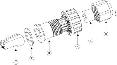
Figure 2-13 Cable Gland Assembly
|
|
|
||
|
|
|
||
|
|
|
Step 5![]() Insert the unterminated end of the Ethernet cable through the sealing nut-end of the cable gland (see Figure 2-13), and pull several inches of cable through.
Insert the unterminated end of the Ethernet cable through the sealing nut-end of the cable gland (see Figure 2-13), and pull several inches of cable through.
Step 6![]() Install an RJ45 connector on the unterminated end of the Ethernet cable using your Ethernet cable installation tool.
Install an RJ45 connector on the unterminated end of the Ethernet cable using your Ethernet cable installation tool.
Step 7![]() Carefully connect the RJ45 cable connector to the PoE port on the access point.
Carefully connect the RJ45 cable connector to the PoE port on the access point.
Step 8![]() Slide the cable gland with the rubber seal towards the access point, and screw the threaded end of the body into the access point, and hand-tighten.
Slide the cable gland with the rubber seal towards the access point, and screw the threaded end of the body into the access point, and hand-tighten.
Step 9![]() Use an adjustable wrench or a 28 mm wrench to tighten the threaded end of the body into the enclosure. Tighten to 15 lb-in.
Use an adjustable wrench or a 28 mm wrench to tighten the threaded end of the body into the enclosure. Tighten to 15 lb-in.
Step 10![]() Use an adjustable wrench and tighten the thread-lock seal nut to 15 lb-in.
Use an adjustable wrench and tighten the thread-lock seal nut to 15 lb-in.
Step 11![]() Route your Ethernet cable, and cut off any excess cable.
Route your Ethernet cable, and cut off any excess cable.
Step 12![]() Install an RJ45 connector on the unterminated cable end, and insert it into the power injector.
Install an RJ45 connector on the unterminated cable end, and insert it into the power injector.
Step 13![]() Turn on the power to the power injector.
Turn on the power to the power injector.
Configuring the Access Point
When you power up an AP that is not connected to a wired Ethernet, fiber-optic, or cable network to the controller, the access point uses the Cisco Adaptive Wireless Path Protocol (AWPP) to bind to another mesh access point with the best path to a root access point (RAP) connected to the wired network to a controller. The access point sends a discovery request when powered up. If you have configured the access point in the controller correctly, the controller sends back a discovery response to the access point. When that happens, the access point sends out a join request to the controller, and the controller responds with a join confirmation response. Then the access point establishes a Control And Provisioning of Wireless Access Points (CAPWAP) connection to the controller and gets the shared secret configured on the controller.
For information on configuring the access point, see the following documents:
- For Lightweight Access Points and Mesh Access Points, see the Cisco Wireless LAN Controller Configuration Guide, which is available at:
http://www.cisco.com/c/en/us/support/wireless/wireless-lan-controller-software/products-installation-and-configuration-guides-list.html
- For a Mobility Express deployment, see the Cisco Mobility Express Configuration and User Guide, available at:
http://www.cisco.com/c/en/us/support/wireless/mobility-express/products-installation-and-configuration-guides-list.html
- For Mesh Access Points, see the Cisco Wireless Mesh Access Points, Design and Deployment Guide, which is available at:
http://www.cisco.com/c/en/us/td/docs/wireless/technology/mesh/8-0/design/guide/mesh80.html
Note![]() The AP does not support daisy chaining.
The AP does not support daisy chaining.
 Feedback