Generic Topic

Architectural Overview

Cisco Hosted Collaboration Solution (HCS) provides industry-leading cloud collaboration services. The HCS data center design is based upon Cisco’s Virtualized Multi-Tenant Data Center (VMDC), later renamed to Virtual Multiservice Data Center, reference architecture. This architecture provides a framework for building fabric-based infrastructure using the Cisco Unified Computing System (UCS) platform as well as an Integrated Compute Stack (ICS). It is based upon traditional three-tier and two-tier data center architectures that brought forth a modular design to deliver networking, computing, and storage resources and services. The combined UCS and ICS form the basic data center building blocks called Points of Delivery (PoD). The PoD serves as a blueprint for the incremental build-out of the Cloud data center in a structured fashion. When resource utilization in a PoD reaches a pre-determined threshold (such as 70 to 80%), you can simply migrate to higher capacity resources (Aggregation or Services devices) or deploy a new PoD.

Starting in HCS 9.2(1) the three-tier, separate core model, was removed which allowed a significant increase in tenant (per customer) capacity. All references to an HCS PoD assumes this collapsed core model. HCS has two PoD architectures; Large PoD and Small PoD. The significant difference between the two is the aggregation switched used. A Large PoD leverages a Nexus 7000 series or Nexus 9500 series switch while a Small PoD leverages a Nexus 5600 series or Nexus 9300 series switch.
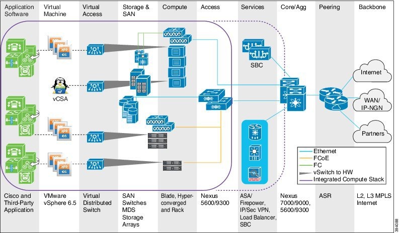
Figure 1. VMDC Collapsed Core PoD Architecture

VMDC Collapsed Core PoD Architecture

Today HCS may be deployed within a Cisco Powered Infrastructure as a Service (IaaS) model that not only includes VMDC but also Cisco Application Centric Infrastructure Fabric (ACI) designs. It also supports a Cisco Powered Hybrid Cloud model based exclusively upon ACI. The one caveat is that all HCS deployments required VMware vSphere as the cloud computing virtualization platform.

The focus of this document is around either HCS PoD deployment models based on VMDC and does not address ACI deployments.

Collaboration Sizing, Configuration and Quoting Tools

The Cisco Unified Communications (UC) Sizing, Configuration and Quoting Tools assists you with hardware sizing for large or complex Cisco Unified Communications solutions. The tools calculate the call-processing requirements for products that have a major impact on performance and scalability.

System engineers or individuals with equivalent Cisco Unified Communications solution experience can use the sizing tools to design and model solutions for existing and prospective customers. The tool requires various types of information to calculate the minimum size and type of devices required for a solution, such as the type and quantity of IP phones, gateways, and media resources. For most device types, the tool also requires the average number of call attempts per hour per device during the busy hour (busy hour call average, or BHCA) and the average usage time. The tool generates calculations that you can copy, save, and send to other users.

Cisco makes assumptions about end-users’ requirements for the purpose of describing Unified Communications (UC) deployment examples in this guide. These assumptions may not align to your specific deployment requirements; use these sizing tools to calculate accurate hardware sizing and VM count. You can access the Unified Communications Tools at www.cisco.com/go/cst.

Getting Started

The first thing you must do to get started with a capacity management plan is to establish a baseline – answer the question: “What is my capacity utilization today?” To answer this question, you must first determine the busiest, recurring period within a reasonable timeframe. For many customers, there is usually a 1-hour period of each day that is typically the busiest. Moreover, there can be busier days of the week (for example Monday vs. Wednesday); busier days of the month (last business day of the month) or busier weeks of the year (for example, the first week in January for insurance companies, or for the United States Internal Revenue Service (IRS), the first two week of April). These traditionally busy hours, days, or weeks represent the most taxing period on the deployment; these are the periods during which a capacity utilization calculation is best because you always want to ensure that your deployment can handle the worst.

The steps to getting started are:

  1. Set up basic sampling (daily).

    Sample the performance counter values: CPU, Memory, Disk, Network, Call and Unified Communications (UC) Application Traffic

  2. Determine the busy period.
    Identify the recurring busy period – worst case scenario – by:
    • Per Component
    • Solution Wide
  3. Establish a baseline of utilization for the target period.
    • Determine hardware capacity utilization
    • Identify components with high capacity utilization
  4. Generate a recurring collection plan.

    Devise a plan that is repeatable – such as automated – that can be done on a weekly basis whereby samples are obtained during the busiest hour of the week.

After you establish a baseline and identify a busy hour, daily sampling is no longer necessary; you must sample only during the busy hour on a weekly basis. However, if regular reporting shows that the busy hour may have changed, then you must complete daily sampling again so that you can identify the new busy hour. After you identify the new busy hour, weekly sampling during the busy hour can resume.

Compute and Storage Infrastructure Capacity Planning

Monitoring a virtual environment is vastly different from monitoring a physical infrastructure. There is no one-to-one correspondence between an operating system instance and a physical server. A typical virtualization host provides shared server, network, and storage resources for multiple operating system instances, each running their own OS and application workload.

As previously mentioned, the UC Sizing Tools are critical to assist with accurate solution sizing. These tools factor in data from performance testing, individual product limits and performance ratings, advanced and new features in product releases, design recommendations from this Cisco Collaboration Systems Release Solution Reference Network Designs (SRND), and other factors. Based on input provided by the system designer, the tools apply their sizing algorithms to the supplied data to recommend a set of hardware resources.

To optimize a virtualized environment, monitoring must encompass virtual resource utilization from the VM's perspective, application service levels, and physical resource utilization on the hosts.

Virtualization monitoring ensures that a virtualized infrastructure performs optimally and that virtual resources are properly allocated. Virtualized infrastructure monitoring requires collecting and evaluating key performance indicators (KPIs) for both physical and virtual components. For example, VMware KPIs include:

  • Datacenters
  • Clusters
  • Datastores
  • Hosts
  • Resource pools
  • Virtual Machines

Because physical resources are shared between VMs, problems that would be localized on a physical server can cascade through the virtualized infrastructure and compromise multiple applications. To cope with virtualization interdependencies, a monitoring strategy is required to optimize resource utilization by recognizing and reacting to performance and availability issues early in a problem cycle.

It is highly recommended that you follow VMware’s Performance Best Practices for VMware vSphere for the specific release you are planning to deploy.

You can access the most current versions of the vSphere documentation by going to:

http://www.vmware.com/support/pubs

You can access performance and other technical papers on the VMware Technical Papers page:

http://www.vmware.com/vmtn/resources

Network Infrastructure Capacity Planning

Network infrastructure is key in the capacity planning process. The information contained in this section serves as reference material to help you plan for present and future capacity requirements for the Service Provider Cisco HCS Data Center.

The overall system capacity in terms of supported subscribers and customers can vary depending on the topology of the network deployed. It is important to regularly track network infrastructure metrics to manage potential growth as Cisco HCS expands.

Network infrastructure metrics are also very important during network integration through a fresh install or when growth occurs in the network that requires software or hardware upgrades.

HCS PoD Tenant Scaling

Along with the recommendations described in Architecture Capacity Planning, the number of customers that can be accommodated in a Cisco HCS PoD configuration is based on the following key factors that are required for each customer:

  • Two VRFs are defined for each HCS customer on the Nexus aggregation switch, one northbound and one toward the Adaptive Security Appliance (ASA)
  • Two HSRP groups are defined, one toward the applications and ASA (inside), and one for the SBC (demarcation device) and ASA (outside)
  • Two VLANs are provided for each HCS customer, one toward the application and one for ASA and Session Border Controller (SBC).
  • Two static routes are provided inside and outside to connect to the ASA firewall
  • One static route is defined to the outside VLAN to connect to the SBC
  • One static route is defined to route traffic to the management domain. This route is for any traffic communication between the management domain and on-premise devices, such as voice gateway, and so on.

The ASA and SBC connect on the same outside VLAN. This means that the outside VLAN of the ASA is same as the inside VLAN of SBC.

The outside of the SBC does not pass through the ASA so that media does not go through the ASA for the inter-customer or off-net calls. Therefore, you can place the SBC and ASA on the same HSRP group and VLAN for SBC inside and ASAs outside VLAN.

You can extend the HSRP group used by the aggregation switch facing toward the application to the ASA (security appliance) on the inside; this saves one HSRP group on the Nexus aggregation switch.

Cisco recommends that you use the static route to connect to the ASA and SBC because dynamic routing (BGP) is not supported on the ASA. Use one static route to route calls from UC applications to the firewall and use one static route to route the incoming specific customer base traffic to the firewall. In HCS deployments, all the communication between an end device and the Cisco Unified Communications Manager goes through the firewall.


Note

Signaling goes through the firewall, but no media goes through the firewall other than the MOH or voicemail.


Define a static route on the Nexus aggregation switch to route the outbound traffic to the SBC and define one static route to route the customer-specific management traffic from the customer premise to the management domain.

Based on the preceding numbers, static routes are the lowest common denominator. If you require four static routes for each Cisco HCS customer in your deployment and only 4,000 static routes are supported on the Nexus 7000, the HCS customer scale numbers can be determined using the following formulas:

  • Number of customers = (Static Routes - 50 Spare)/Static Route per customer
  • Number of customers = (BGP peers - 20 Spare) / BGP peers per customer
  • Number of customers = HSRP Groups - 40 Spare) / HSRP per customer
  • Number of customers = (VRF - 10 Spare) / VRF per customer
  • Number of customers = (VLANs - 100 Spare) /VLAN per customer

When deploying an over-the-Internet model for the same enterprises that have the MPLS-enabled HCS, there is no change to the maximum number of customers. If a service provider onboards only over-the-Internet customers, they still require four static routes per customer. Therefore, the maximum number of customers for the following deployments is the same:

  • Cisco HCS deployment
  • Cisco HCS deployment with over-the-top traffic (OTT)
  • Cisco HCS deployment with TP
  • Cisco HCS deployment with TP and OTT