Solution Capacity Planning

Architectural Overview

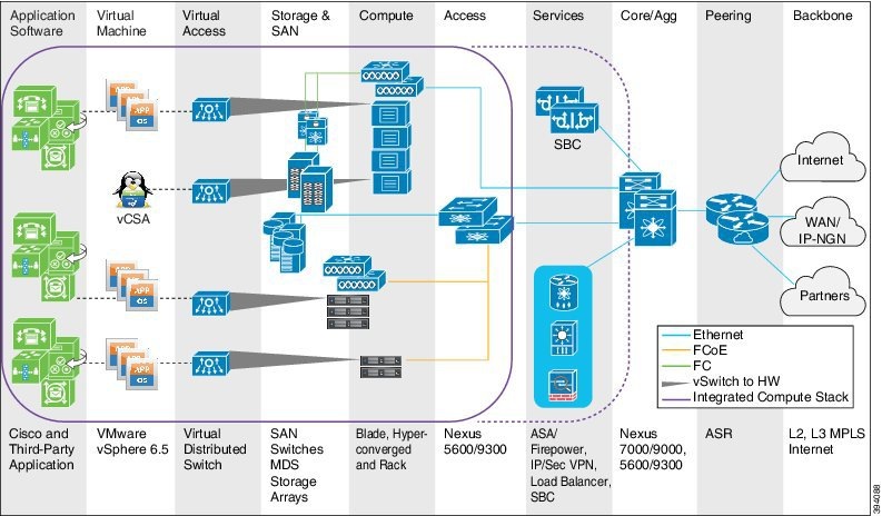
Cisco Hosted Collaboration Solution (HCS) provides industry-leading cloud collaboration services. The HCS data center design is based upon Cisco’s Virtualized Multi-Tenant Data Center (VMDC), later renamed to Virtual Multiservice Data Center, reference architecture. This architecture provides a framework for building fabric-based infrastructure using the Cisco Unified Computing System (UCS) platform as well as an Integrated Compute Stack (ICS). It is based upon traditional three-tier and two-tier data center architectures that brought forth a modular design to deliver networking, computing, and storage resources and services. The combined UCS and ICS form the basic data center building blocks called Points of Delivery (PoD). The PoD serves as a blueprint for the incremental build-out of the Cloud data center in a structured fashion. When resource utilization in a PoD reaches a pre-determined threshold (such as 70 to 80%), you can simply migrate to higher capacity resources (Aggregation or Services devices) or deploy a new PoD.

Starting in HCS 9.2(1) the three-tier, separate core model, was removed which allowed a significant increase in tenant (per customer) capacity. All references to an HCS PoD assumes this collapsed core model. HCS has two PoD architectures; Large PoD and Small PoD. The significant difference between the two is the aggregation switched used. A Large PoD leverages a Nexus 7000 series or Nexus 9500 series switch while a Small PoD leverages a Nexus 5600 series or Nexus 9300 series switch.

Figure 1. VMDC Collapsed Core PoD Architecture

VMDC Collapsed Core PoD Architecture

Today HCS may be deployed within a Cisco Powered Infrastructure as a Service (IaaS) model that not only includes VMDC but also Cisco Application Centric Infrastructure Fabric (ACI) designs. It also supports a Cisco Powered Hybrid Cloud model based exclusively upon ACI. The one caveat is that all HCS deployments required VMware vSphere as the cloud computing virtualization platform.

The focus of this document is around either HCS PoD deployment models based on VMDC and does not address ACI deployments.

Architecture Capacity Planning

Cisco HCS system capacity is determined by system performance requirements rather than by strict limits. Overall system performance is impacted by key parameters such as tenant size, network topology, subscriber feature profile, redundancy, and call profile.

The following diagram depicts the HCS PoD architecture with a collapsed core network design. This diagram also omits a separate Access Layer switch, which is optional.

Figure 2. HCS Architectural Reference

HCS Architectural Reference

High Availability

High availability (HA) refers to system design that ensures a high level of operational continuity over a given period. It encompasses a variety of business goals and technical requirements, from hardware targets to overall service targets, with a common purpose of minimizing unplanned downtime. The goal for HA systems is to avoid risks that may lead to short-term or long-term service interruptions.

To meet HA targets, the system design must protect and recover components against minor outages in a short time frame. The recovery mechanism should be automated to minimize the potential for failure and focused on uptime rather than recovery time.


Note

Recovery Time Objectives may vary among service providers and their customers. Service providers should consult Cisco regarding specific requirements in this area, so that a Service Level Agreement can capture these requirements.


Capacity Planning

HCS and Cisco Collaboration Technology comprises an array of products to build complete end-to-end collaboration solutions for virtually any size or type of enterprise. Cisco HCS consists of the following main elements:

Figure 3. Cisco Collaboration Architecture (Conceptual View)

Cisco Collaboration Architecture (Conceptual View)

Network, call routing, and call control infrastructures as well as Unified Communications and Collaboration applications and services must be designed and deployed with an understanding of the capacity and scalability of the individual components and the overall system. Similarly, deployment of operations and serviceability components and services must also be designed with attention to capacity and scalability considerations. When deploying various operations and serviceability applications and components, not only is it important to consider the scalability of these applications themselves, but you must also consider the scalability of the underlying infrastructures. Certainly, the network infrastructure must have available bandwidth and be capable of handling the additional traffic load that those operations will create. Likewise, the call routing and control infrastructure must be capable of handling required inputs and outputs as facilitated by the various operations and serviceability components in use.

For example, with operational applications and services such as voice quality monitoring and alerting and operations and fault monitoring, there are capacity implications for each of these individual applications or services in terms of the number of devices and call flows that can be monitored at a given time, but just as important is the scalability of the underlying infrastructure and monitored applications to handle the added network traffic and connections required for monitoring and alerting. While the monitoring and alerting application or service itself may be able to support the monitoring of many network devices and call flows, the underlying network or devices might not have available capacity to handle the probing connections or the alarm messaging load generated by the monitoring and alerting services.

For operation applications or services that provide user or device provisioning capabilities, capacity planning considerations include things such as ensuring that the provisioning application can handle the requested load and also that user or device provisioning operations not only do not exceed the number of support devices or users for a particular underlying Unified Communications application or service, but also that provisioning or configuration change transactions do not exceed either the capacity of the underlying network or the rate at which a particular application can handle transactions. In most cases additional capacity can be added by increasing the number of operational provisioning application servers or by increasing the size or number of underlying Unified Communications and Collaboration applications or service instances, assuming the underlying network and call routing and control infrastructures are capable of handling this additional load.

Therefore, the goal of capacity planning within HCS is to plan so well that new capacity is added just in time to meet the anticipated need but not so early that resources go unused for a long period. Successful capacity planning is one that makes the trade-offs between the present and the future that overall prove to be the most cost-efficient.

Capacity planning is also not a one-time task and should be part of ongoing service delivery operations. A reliable capacity management plan helps prevent outages because the data supports proactive modifications to the deployment that ultimately prevent an outage.

Capacity planning can be broken down into three steps: determining service level requirements, analyzing current capacity, and forecasting future requirements (or modeling). Adequate monitoring is key to determining current capacity and forecasting future capacity requirements.

Determining Service Level Requirements

A “service level agreement” (SLA) lays out the acceptable parameters between the service provider and the subscriber that defines the level of service expected from the service provider. SLAs are output-based in that their purpose is specifically to define what the customer will receive. SLAs do not define how the service itself is provided or delivered and is not the focus of this guide however it is still an integral component to determine the capacity required.

Current Capacity

The overall supportable size of a Cisco HCS system depends on many factors. As previously stated, it is important to monitor key metrics to understand current usage patterns and to be able to project forecasted growth as a function of time. Customer requirements, usage patterns and growth as well as software licenses and features enabled on the system all play a role in determining the maximum capacity of a system.

Once the network, call routing, call control infrastructure, and applications and services have been put in place for your Cisco Unified Communications and Collaboration System, network and application management components can be added or layered on top of that infrastructure. There are numerous applications and services that can be deployed in an existing Cisco Unified Communications and Collaboration infrastructure to monitor and manage the operations of the system. These applications and services can be classified into four basic areas:

  • User and device provisioning services — Provide the centralized ability to provision and configure users and devices for Unified Communications and Collaboration applications and services.
  • Voice quality monitoring and alerting — Provide the ability to monitor on an ongoing basis various call flows occurring within the system to determine whether voice and video quality are acceptable and to alert administrators when the quality is not acceptable.
  • Operations and fault monitoring — Provides the centralized ability to monitor all application and service operations and to issue alerts to administrators regarding network and application failures.
  • Network and application probing — Provides the ability to probe and collect network and application traffic information at various locations throughout the deployment and to allow administrators to access and retrieve this information from a central location.

The following table provides lists the monitoring and management sources of system data that are available for a typical HCS deployment.

Table 1. System Data Availability
Assurance Management Product Fulfillment and Assurance Provided Monitored Cisco HCS Devices
Cisco Adaptive Security Device Manager Provisioning, Performance, and Inventory Cisco firewall appliances and firewall service modules
Cisco Data Center Network Manager Provisioning, Performance, and Inventory NX-OS network deployments including LAN fabrics, SAN fabrics, and IP Fabric for Media (IPFM)
Cisco HCM-F Provisioning, Performance, and Inventory Cisco Unified Computing System (UCS), Cisco HCM-F, Unified Communications Domain Manager, UC Applications
Cisco Intersight Device Fault, Availability, Performance, and Inventory Cisco UCS, HyperFlex, and third-party infrastructure
Cisco Prime Collaboration Assurance Device Fault, Availability, Performance, and Diagnostics UC Applications and Network Devices
Cisco Prime Collaboration Deployment Provisioning UC Applications
Cisco UCS Manager Device Fault, Availability, and Performance UCS Hardware
VMware vCenter / vCenter Server Appliance Device Fault, Availability, and Performance ESXi Hypervisor, VMs, Virtual Distributed Switch (VDS)

Note

Cisco HCM-F will deprecate the support of Cisco Unified Communications Domain Manager in the upcoming releases with limited support for existing integration, Cisco HCS partners and customers are advised to take necessary steps to align their requirements.