Cisco Contact Center Gateway Deployment Example

Example Topology

This chapter provides an example of how to deploy a Cisco Contact Center Gateway. The procedures create a working example of a Parent/Child system. This example introduces you to the concepts and tasks that are involved in a successful deployment.


Note

The procedures show how to set up and configure one side of the redundant components. Set up and configure the other side on your own.


The example is based on the illustrated deployment.

Figure 1. Example Deployment

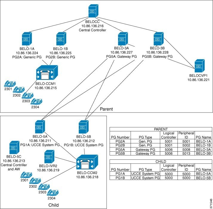
The Parent site consists of these components:

  • Central Controller (BELOCC)

  • Redundant Generic PGs, PG2A (BELO-1A) and PG2B (BELO-1B), which interface with the parent Unified Communications Manager (BELO-CCM1)

  • Unified Communications Manager (BELO-CCM1), which routes calls to these extensions: DNs 2301-2304

  • CVP (BELO-CVP1)

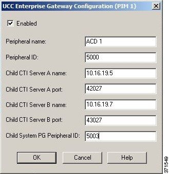
  • Redundant Unified CCE Gateway PGs, PG5A (BELO-3A) and PG5B (BELO-3B), which interface with the child redundant System PGs (PG1A and PG1B)

The Child site consists of these components:

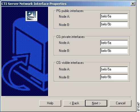
  • Redundant Unified CCE System PGs, PG1A (BELO-5A) and PG1B (BELO-5B), which interface between the parent redundant Unified CCE Gateway PGs (BELO-3A and BELO-3B) and the Unified Communications Manager (BELO-CCM2)

  • Unified Communications Manager (BELO-CCM2), which routes calls to the local extensions (DNs 2301-2304) and to the IP IVR (BELO-IVR2)

  • IP IVR (BELO-IVR2)

  • A Central Controller and an Administration & Data Server (BELO-5C)

Example Prerequisites

The example assumes that you:

  • Installed the appropriate contact center software on each machine as described in Cisco Unified Contact Center Enterprise Installation and Upgrade Guide at https://www.cisco.com/c/en/us/support/customer-collaboration/unified-contact-center-enterprise/products-installation-guides-list.html. The installation places the files into a machine's \bin directory.

  • Are familiar with using the Domain Manager.

  • Installed and configured the Unified Communications Manager.

  • Configured the extensions (DNs) from 2301 to 2304.

  • Configured the local route points in this table:

    Route point

    Target

    2500

    Any available skill group

    2501

    SG01

    2502

    SG02

  • Added the Facility and the Instance.

Deploy the Child System

To deploy the example child system, you perform the following tasks:

  1. Run the Web Setup Tool to set up the child Administration & Data Server on BELO-5C.
  2. Run the Web Setup Tool and ICMDBA to set up the child Central Controller (CC) on BELO-5C.
  3. On the Administration & Data Server, run the Configuration Manager to add the System PGs. This task assigns the Logical Controller IDs (LCID) and the Peripheral IDs (PID) that are required during setup.
  4. Run the PG Setup Tool on BELO-5A and BELO-5B to setup PG1A and PG1B, respectively.
  5. Install and configure JTAPI, the CTI Server, and a desktop application on the System PGs.
  6. Use the Configuration Manager tools to configure the Agents, Skill Groups, Skill Group Members, Dialed Numbers, and Call Types.
  7. Use the Script Editor to manage Call Types, and to create and schedule routing scripts.

Set Up Child Administration & Data Server

To set up the Administration & Data Server, run the Web Setup Tool for the Administration & Data Server on BELO-5C.

Procedure


Step 1

Run the Web Setup Tool on the computer designated as the child Central Controller (BELO-5C).

Step 2

Click Instance Management, then click Add. The Add Instance dialog appears.

Step 3

Select BELO (the Facility), then bh03 (the Instance to add).

Step 4

Click Save.

Step 5

Select Administration & Data Server, then click Add. The Add Administration & Data Server dialog appears.

Step 6

Set the deployment model.

  1. Select bh03 (the Instance) from the drop-down menu.

  2. Select Enterprise as the deployment type.

  3. Select Small to Medium for the deployment size.

  4. Click Next.

Step 7

Set the role for the Administration & Data Server.

  1. Select Administration Server and Real-time Reporting.

  2. Click Next.

Step 8

Set the Administration & Data Server connectivity.

  1. Select Primary Administration & Data Server.

  2. Enter BELO-5C as the Secondary Administration & Data Server.

    You use the same Administration & Data Server as the primary for the secondary since there is only one.
  3. Enter BELO-5C-Site1 for the site name.

  4. Click Next.

Step 9

Set the database and options by accepting the default settings, then click Next.

Step 10

Set the Central Controller connectivity.

  1. Enter BELO-5C into each name field.

  2. Ensure that the Central Controller Domain is set to BELODC.cisco.com.

  3. Select Side A Preferred.

  4. Click Next.

    The Summary window appears.
Step 11

Verify that all settings are correct, then click Next.

The system configures the Administration & Data Server. Then the Administration & Data Server window appears and displays the Administration & Data Server information.

Set Up Child Central Controller

To set up the child Central Controller, you first run the Web Setup Tool for the CallRouter and then run the ICMDBA to create the Logger database. You perform both tasks on the Central Controller virtual machine (BELO-5C).

Set Up Child CallRouter

Run the Web Setup Tool on BELO-5C.

Procedure

Step 1

Run the Web Setup Tool.

Step 2

Click Routers.

Step 3

Click Add to set up the CallRouter.

The Deployment dialog appears.
Step 4

On the Deployment dialog:

  1. Ensure that the Instance is set to bh03.

  2. Select Side A.

  3. Select the appropriate Fault Tolerance mode, either Simplex or Duplex.

  4. Click Next.

The Router Connectivity dialog appears.
Step 5

Ensure all the fields indicate BELO-5C, then click Next.

The Enable Peripheral Gateways dialog appears.
Step 6

Enter 1 to indicate the number of PGs that you are deploying, then click Next.

The Router Options dialog appears.
Step 7

Leave all settings at the default (nothing selected) and click Next.

The Summary dialog appears.
Step 8

Ensure that the Router summary is correct, then click Finish.

When the CallRouter setup completes, the Router successfully saved window appears.

Set Up Child Logger

To set up the child Logger on BELO-5C, you create a Logger database and then run the Web Setup Tool.

Procedure

Step 1

Choose Start > All Programs > Unified ICM-CCE Tools > ICMDBA.

Step 2

Create the Logger database.

For detailed information on creating a Logger database, see the Administration Guide for Cisco Unified Contact Center Enterprise at https://www.cisco.com/c/en/us/support/customer-collaboration/unified-contact-center-enterprise/products-maintenance-guides-list.html.
Step 3

Run the Web Setup Tool.

Step 4

Click Loggers.

The Logger dialog appears.
Step 5

Click Add to set up the Logger.

The Deployment dialog appears.
Step 6

On the Deployment dialog:

  1. Ensure that the Instance is set to bh03.

  2. Ensure that the Logger Type is set to Enterprise.

  3. Select Side A.

  4. Select the appropriate Fault Tolerance mode, either Simplex or Duplex.

  5. Click Next.

The Central Controller Connectivity dialog appears.
Step 7

Ensure that the Router Private Interfaces (Side A and Side B) and the Logger Private Interfaces (Side A and Side B) are set to BELO-5C. Then, click Next.

The Additional Options dialog appears.
Step 8

Leave the default settings and click Next.

The Summary dialog appears.
Step 9

Ensure that the Logger summary is correct, then click Finish.

When the Logger setup completes, the Logger successfully saved window appears.

What to do next

You have added an Administration & Data Server and a Central Controller to the Child system. Exit the Web Setup Tool. On the child Administration & Data Server, open the ICM Service Control and start the distributor, logger, and router processes.

Add System PGs on Child Administration & Data Server

On the Administration & Data Server, run the Configuration Manager to add the System PGs.

Configure System PGs

Use the Configuration Manager tools to add and configure the System PGs.

Procedure

Step 1

Choose Start > All Programs > Cisco Unified CCE Tools > Administration Tools > Configuration Manager.

Step 2

Start the PG Explorer Tool and click Retrieve.

Step 3

Click Add PG to create both the Peripheral Gateway and the Peripheral.

  1. Enter UCCE for the Name.

  2. Select UCCE System for the Client Type.

  3. If no desk settings are set, set them and click OK.

    The Agent Desk Settings List Tool appears.
  4. Click Add.

    The Attribute tab appears.
  5. Enter default for the Name.

  6. Leave all other settings at their defaults and click Save.

  7. Close the Agent Desk Settings List Tool.

Step 4

Go back to the PG Explorer Tool.

  1. Select UCCE-1 as the Peripheral.

  2. On the Peripheral tab, set the Default Desk Settings to default.

  3. On the Agent Distribution tab, click New.

  4. Set the Administration & Data Server site name to BELO-5C-Site 1 and leave all other settings at their defaults.

  5. On the Routing Client tab, enter UCCE_RC for the Name and leave all other settings at their defaults.

  6. Click Save.

    The Logical Controller tab now indicates the Logical Controller ID (5000) and the Physical Controller ID (5000).

What to do next

The Central Controller setup and configuration is complete. You can now install and set up the Peripheral Gateways to communicate with the Central Controller.

Add Instances on Child System

Use the Web Setup Tool to add the Instance on the child System PG virtual machines BELO-5A (PG1A) and BELO-5B (PG1B).

Procedure

Step 1

Enter http://BELO-5B/setup (or BELO-5A, for the other side) and log in to the Web Setup Tool to add the Instance.

The main Web Setup Tool window appears.
Step 2

Click Instance Management, then click Add.

The Add Instance dialog appears.
Step 3

Select BELO (the Facility) and then bh03 (the Instance to add).

Step 4

Click Save.

Step 5

Click Log Out.


Set Up System PGs

Use the PG Setup Tool to add and configure the System PGs. This example procedure sets up Side B of PG1.

Procedure


Step 1

Click PG Setup Tool.

The main PG Setup Tool window appears.
Step 2

Click Add in the Instance Component section.

The ICM/CCEComponent Selection dialog appears.
Step 3

Select Peripheral Gateway.

The Peripheral Gateway Properties dialog appears.
Step 4

Ensure that all check boxes in the Node Manager Properties section are checked.

Step 5

Ensure that PG1 and the appropriate side are selected in the PG Node Properties dialog.

Step 6

Select UCCE System for the Client Type, then click Add.

Step 7

Click Next.

The Peripheral Gateway Component Properties dialog appears.
Step 8

Click Add.

The Add PIM dialog appears.
Step 9

Select UCCE System and PIM 1, then click OK.

The UCCE System Configuration (PIM1) dialog appears.
Step 10

Check Enabled.

Step 11

Add the PID of 5000.

Step 12

Enter an Agent Extension Length of 4.

Step 13

Set the Service to 10.86.136.218 (the IP address of the Unified Communications Manager BELO-CCM2).

Step 14

Enter BELO for the User Id (an application user created on the Unified Communications Manager).

Step 15

Enter cisco for the User password (set in the Unified Communications Manager).

Step 16

Click OK.

You return to the Peripheral Gateway Component Properties dialog.

Step 17

Change the LCID to 5000 (the same LCID that you used in the PG Explorer Tool).

Step 18

Click Next.

The Device Management Protocol Properties dialog appears.
Step 19

Leave all settings at their default values and click Next.

The Peripheral Gateway Network Interfaces dialog appears.

Step 20

Set the PG fields to BELO-5A and BELO-5B, as applicable.

Step 21

Set the Router fields to BELO-5C.

Step 22

Click Next.

The Check Setup Information dialog appears.

Step 23

If all the settings are correct, click Next.

After the System PG setup completes, the Setup Complete dialog appears.
Step 24

Click Finish.

You return to the main PG Setup Tool window.
Step 25

Click Exit Setup.

Step 26

Go to the Unified Communications Manager, then download and install the JTAPI plugin for Windows on the System PGs.

  1. Select Application > Plugins.

  2. Click Find.

  3. Next to Cisco JTAPI for Windows, click Download.

  4. Install the downloaded file, ciscojtapiclient.exe, accepting all the default settings.

Step 27

Start the PG1A and PG1B services on each System PG (BELO-5A and BELO-5B).


Install CTI Server on Child System

Use the PG Setup Tool to install CTI Server on the System PGs (BELO-5A and BELO-5B). In this section, you install CTI Server on side B of PG1.

Procedure


Step 1

Using Service Control, stop the PG service.

Step 2

Start the PG Setup Tool.

The Cisco Unified ICM/Contact Center Enterprise Components Setup dialog appears.
Step 3

Click Add in the Instance Components section.

The ICM/CCE Component Selection dialog appears.
Step 4

Select CTI Server.

The CTI Server Properties dialog appears.
Step 5

Check Duplexed CTI Server and ensure that all the other check boxes are checked as well.

Step 6

Select CG 1 as the CG Node ID.

Step 7

Enter 1 for the ICM system ID (the same as the Device Management Protocol (DMP) and the PG ID).

Step 8

Click Next.

The CTI Server Component Properties dialog appears.
Step 9

Leave the default port setting of 43147, then click Next.

The Network Interface Properties dialog appears.

Step 10

Enter BELO-5A and BELO-5B as applicable, then click Next.

The Check Setup Information dialog appears.
Step 11

Check that all settings are correct, then click Next.

The Setup Complete dialog appears.
Step 12

Click Finish.

You return to the main PG Setup window.
Step 13

Click Exit Setup.

Step 14

Start the PG and CG services using the ICM/CCE Service Control application and check to ensure that they are running properly.


Install Desktop Application on System PGs

You can install a desktop application on the PGs to enable testing. You can use any desktop application (CTI OS, or custom desktops) for this purpose.

Configure Agents on Child Central Controller

Use the Configuration Manager Agent Explorer tool to configure agents on the child Central Controller.

Procedure


Step 1

Start the Agent Explorer tool.

Step 2

On the main window of the Agent Explorer tool, click Retrieve.

Step 3

Click Add Agent.

The Agent tab appears.
Step 4

Complete all the fields except the Password and the Peripheral Name fields.

The agent name information appears in the list, as with all Explorer tools.
Step 5

Add at least three agents.

Step 6

Save your work and close the Agent Explorer tool.


Configure Skill Groups on Child Central Controller

Use the Configuration Manager Skill Group Explorer Tool to configure skill groups SG01 and SG02 on the child Central Controller.

Procedure


Step 1

Start the Skill Group Explorer Tool.

Step 2

On the main window of the Skill Group Explorer Tool, click Retrieve.

Step 3

Click Add Skill Group.

The Skill Group tab appears.
Step 4

Complete all the fields and click OK.

The skill group name appears in the list, as with all Explorer tools.
Step 5

Select the Skill Group Member tab and click Add.

The Add Skill Group Member dialog appears.
Step 6

Select the agents to add to the skill group, then click OK.

The agents become members of the skill group.
Step 7

Select the skill group in the tree list, then click Add Route.

The Route tab appears.
Step 8

Provide the Route Name and click Save.

The route name appears in the tree list and the skill group is added to the peripheral.
Step 9

Add one more skill group.

Step 10

Save your work and close the Skill Group Explorer Tool.


Configure Dialed Numbers on Child Central Controller

Use the Configuration Manager Dialed Number/Script Selector List Tool to configure dialed numbers on the child Central Controller.

Procedure


Step 1

Start the Dialed Number/Script Selector List Tool.

Step 2

On the main window of the Dialed Number/Script Selector List Tool, click Retrieve.

Step 3

Click Add.

The Dialed Number Attributes tab appears.
Step 4

Select UCCE_RC as the Routing Client.

Step 5

Select Cisco_Voice for the Media Routing Domain.

Step 6

Set the Dialed Number String/Script Selector to 2500 (the route point set up on the Unified Communications Manager).

Step 7

Set UCCE_RC_2500 as the Name, then select bh03 as the Customer setting.

Step 8

Check Permit Application Routing on the route points controlled by the Parent (the Post route points and the Translation route points).

This option provides the link between the Parent and the Child. The option gives the Parent visibility to the Dialed Number so that the Parent can handle the DN.
Step 9

Click Save.

The dialed number appears in the tree list.
Step 10

Add two more dialed numbers (one for each skill group).

When complete, you have the following DNs:

– 2500, which is named UCCE_RC_2500 and connects to all the skill groups.

– 2501, which is named UCCE_RC_2501 and connects to SG01.

– 2502, which is named UCCE_RC_2502 and connects to SG02.

Step 11

Save your work and close the Skill Group Explorer Tool.


Configure Call Types on Child Central Controller

Use the Configuration Manager Call Type List tool to configure call types on the child Central Controller.

Procedure


Step 1

Start the Call Type List tool.

Step 2

On the main window of the Call Type List tool, click Retrieve.

Step 3

Click Add.

The Call Type Attributes tab appears.
Step 4

Set internal_2500CT as the Name, then select bh03 as the Customer setting.

Step 5

Click Save.

The call type appears in the tree list.
Step 6

Add two more call types (internal_2501CT and internal_2502CT).

When complete, you have the following call types: internal_2500CT, internal_2501CT, and internal_2502CT.
Step 7

Save your work and close the Call Type List tool.


Create and Schedule Routing Scripts on Child

A routing script determines how a call is handled by establishing the routing rules. In this section, you create a routing script and schedule it. You can then log in agents and have them make and accept calls.

For more information about scripting, see Scripting and Media Routing Guide for Cisco Unified ICM/Contact Center Enterprise at https://www.cisco.com/c/en/us/support/customer-collaboration/unified-contact-center-enterprise/products-user-guide-list.html.

Procedure


Step 1

Start the Script Editor application on the Administration & Data Server.

Step 2

Create the first routing script, named internal_2500.

  1. Set the Skill Group node to UCCE_1.Cisco_Voice.SG01 and UCCE_1.Cisco_Voice.SG02.

  2. Set the Queue to Skill Group node to UCCE_1.Cisco_Voice.SG01 and UCCE_1.Cisco_Voice.SG02.

  3. Set the Wait node to 10 seconds.

Step 3

Save the script.

Step 4

Choose Script > Call Type Manager.

The Call Type Manager appears.
Step 5

Select Media Routing Domain and Dialed Number.

This setting associates the call type with the dialed number.
Step 6

Click Add.

The Dialed Number Entry dialog appears.
Step 7

Associate the dialed number with the call type by selecting internal_2500CT (the call type), then click OK.

Step 8

To schedule the routing script, click the Schedule tab.

Step 9

Click Add.

The Call Type Scheduling dialog appears.
Step 10

Accept all the default settings on each of the rest of the tabs, then click OK.

You return to the Call Type Manager.
Step 11

Click OK.

You now have a system that allows you to log in agents and have them make and accept calls.

Deploy the Parent System

To deploy the example parent system, you perform the following tasks:

  1. Run the Web Setup Tool to set up the Administration & Data Server on BELO-CC.
  2. Run the Web Setup Tool and ICMDBA to set up the Central Controller (CC) on BELO-CC. You use the Web Setup Tool to set up the CallRouter and Logger and the ICMDBA to create the Logger database.
  3. On the Administration & Data Server, run the Configuration Manager to add the Enterprise Gateway PGs (BELO-3A and BELO-3B). This step assigns the Logical Controller IDs (LCID) and the Peripheral IDs (PID) required during setup.
  4. Run the PG Setup Tool on BELO-3A and BELO-3B to setup PG5A and PG5B, respectively.
  5. Configure and set up the Generic PGs. Install and configure JTAPI, the CTI Server, and a desktop application on the generic PG.
  6. Use the Configuration Manager tools to configure the Agents, Skill Groups, Skill Group Members, Dialed Numbers, and Call Types.
  7. Use the Script Editor to manage Call Types, and to create and schedule routing scripts.

Set Up Parent Administration & Data Server

To set up the Administration & Data Server, run the Web Setup Tool for the Administration & Data Server on BELO-CC.

Follow the same procedure as Set Up Child Administration & Data Server.

Set Up Parent Central Controller

To set up the parent Central Controller, you first run the Web Setup Tool for the CallRouter and then run the ICMDBA to create the Logger database. You perform both tasks on the Central Controller virtual machine (BELO-CC).

Set Up Parent CallRouter

Run the Web Setup Tool on BELO-CC.

Follow the same procedure as Set Up Child CallRouter.

Set Up Parent Logger

To set up the parent Logger on BELO-CC, you create a Logger database and then run the Web Setup Tool.

What to do next

You have added an Administration & Data Server and a Central Controller to the Parent system. Exit the Web Setup Tool. On the parent Administration & Data Server, open the ICM Service Control and start the distributor, logger, and router processes.

Follow the same procedure as Set Up Child Logger.

Add Enterprise Gateway PGs on Parent Administration & Data Server

On the Administration & Data Server, run the Configuration Manager to add the Enterprise Gateway PGs.

Configure Enterprise Gateway PGs

Use the Configuration Manager tools to add and configure the Enterprise Gateway PGs.

Procedure

Step 1

Select Start > All Programs > Cisco Systems, Inc. > Administration & Data Server Tools > Configuration Manager.

Step 2

Start the PG Explorer Tool and click Retrieve.

Step 3

Click Add PG to create both the Peripheral Gateway and the Peripheral.

  1. Enter ACMI for the Name.

  2. Select Client Type.

Step 4

Go back to the PG Explorer Tool.

  1. Select ACMI-1 as the Peripheral.

  2. On the Agent Distribution tab, click New.

  3. Set the Administration & Data Server site name to BELO-CC-Site 1 and leave all other settings at their defaults.

  4. On the Routing Client tab, enter ACMI-1_RC for the Name and leave all other settings at their defaults.

  5. Click Save.

    The Logical Controller tab now indicates the Logical Controller ID (5006), the Physical Controller ID (5006), and the Peripheral ID(5000).

Add Instance on Parent System

Use the Web Setup Tool to add the Instance on the parent Enterprise Gateway PG virtual machines BELO-3A (PG5A) and BELO-3B (PG5B).

Procedure

Step 1

Enter http://BELO-3B/setup (or BELO-3A, for the other side) and log in to the Web Setup Tool to add the Instance.

The main Web Setup Tool window appears.
Step 2

Click Instance Management, then click Add.

The Add Instance dialog appears.
Step 3

Select BELO (the Facility) and then bh01 (the Instance to add).

Step 4

Click Save.

Step 5

Click Log Out.


Set Up Enterprise Gateway PGs

Use the PG Setup Tool to set up the Enterprise Gateway PG virtual machines BELO-3A (PG5A) and BELO-3B (PG5B).

Procedure


Step 1

Click PG Setup Tool.

Step 2

Click Add in the Instance Component section.

The ICM/CCE Component Selection dialog appears.
Step 3

Select Peripheral Gateway.

The Peripheral Gateway Properties dialog appears.
Step 4

Ensure that all check boxes in the Node Manager Properties section are checked.

Step 5

Ensure that PG5 and the appropriate side are selected in the PG Node Properties dialog.

Step 6

Select UCC Enterprise Gateway for the Client Type, then click Add.

Step 7

Click Next.

The Peripheral Gateway Component Properties dialog appears.
Step 8

Click Add.

The Add PIM dialog appears.
Step 9

Select UCCE Enterprise Gateway and PIM 1, then click OK.

The UCCE Enterprise Gateway Configuration (PIM1) dialog appears.
Step 10

Check Enabled.


Note 

The Peripheral ID is for Unified CCE and is set based on your system configuration.

Note 

During the installation of the Unified CCE Gateway PG on a Unified CCE child, the child System PG's Peripheral ID is read from the parent Unified ICM's PG_ICID registry variable.

Step 11

Add the PID of 5008 for the UCCE Enterprise Gateway PG on the Parent.

Step 12

Enter BELO-5A for the System PGA name.

Step 13

Enter 42027 for the System PGA port (the CTI Server port).

Step 14

Enter BELO-5B for the System PGB name.

Step 15

Enter 43027 for the System PGB port (the CTI Server port).

Step 16

Enter 5000 for the Child System PG PID.

Step 17

Click OK.

You return to the Peripheral Gateway Component Properties dialog.
Step 18

Change the LCID to 5006 (the same LCID that you used in the PG Explorer Tool).

Step 19

Click Next.

The Device Management Protocol Properties dialog appears.
Step 20

Leave all settings at their default values and click Next.

The Peripheral Gateway Network Interfaces dialog appears.
Step 21

Set the PG fields to BELO-3A and BELO-3B, as applicable.

Step 22

Set the Router fields to BELO-CC.

Step 23

Click Next.

The Check Setup Information dialog appears.
Step 24

If all the settings are correct, click Next.

The Enterprise Gateway PGs are set up.
Step 25

Click Finish.

You return to the main PG Setup Tool window.
Step 26

Click Exit Setup.

Step 27

Start the PG5A and PG5B services on each Enterprise Gateway PG (BELO-3A and BELO-3B).


Configure and Set up Generic PGs

You have set up the Systems PGs and the Enterprise Gateway PGs. Use the same tools to set up the Generic PGs (PG2A on BELO-1A and PG2B on BELO-1B). You can find the necessary information in the illustration of the example topology.

Install CTI Server on Parent System

Use the PG Setup Tool to install CTI Server on the Generic PGs (PG2A and PG2B).

Procedure


Step 1

Using Service Control, stop the PG service.

Step 2

Start the PG Setup Tool.

The Cisco Unified ICM/Contact Center Enterprise Components Setup dialog appears.
Step 3

Click Add in the Instance Components section.

The ICM/CCE Component Selectiondialog appears.
Step 4

Select CTI Server.

The CTI Server Properties dialog appears.
Step 5

Check Duplexed CTI Server and ensure that all the other check boxes are checked as well.

Step 6

Select CG 2 as the CG Node ID.

Step 7

Enter 2 for the ICM system ID (the same as the Device Management Protocol (DMP) and the PG ID).

Step 8

Click Next.

The CTI Server Component Properties dialog appears.
Step 9

Leave the default port setting of 42147, then click Next.

The Network Interface Properties dialog appears.
Step 10

Enter BELO-1A and BELO-1B as applicable, then click Next.

The Check Setup Information dialog appears.
Step 11

Check that all settings are correct, then click Next.

The Setup Complete dialog appears.
Step 12

Click Finish.

You return to the main PG Setup window.
Step 13

Click Exit Setup.

Step 14

Start the PG and CG services using the ICM/CCE Service Control application and check to ensure that they are running properly.


Install Desktop Application on Generic PGs

You can install a desktop application on the PGs to enable testing. You can use any desktop application (Cisco Finesse, CTI OS, or custom desktops) for this purpose.

Autoconfiguration with Enterprise Gateway

For Contact Center Gateway deployments with a Unified CCE child, you configure Call Types as Services. By default, autoconfiguration is enabled in the Peripheral tab of the PG Explorer. Autoconfiguration takes effect when the PG starts.

When autoconfiguration occurs between the parent Unified ICM and the child Unified CCE, the following Unified ICM tables are populated:

  1. Agent/Person

  2. Skill Group

  3. Service


Note

Autoconfiguration of like entities occur on the parent for Agent and Skill Group, but not for Call Type (child) and Service (parent).


Default skill groups on the child, which are not viewable, get created as real skill groups on the parent. Activity done in the default skill group on the child shows up in these real skill groups on the parent.

Set up the Service members on the parent. To set up the service members for any given service, examine the script for a call type on the child. Note the skill groups to which the script offers the call. On the parent, use that list of skill groups to make service members for that Service.


Note

Autoconfiguration does not provide complete configuration for Unified ICM software. Autoconfiguration only configures agents, services, skill groups, and skill group members. You must set up many other elements, such as dialed numbers, scripts, peripheral targets, and routes, manually.


If any error occurs during autoconfiguration, the keys on the parent do not update. The Unified CCE PIM uploads the entire child configuration for comparison every time that the PIM starts until no configuration errors are encountered.

Configuration changes on the child Unified CCE do not get correctly reflected on the parent while the Unified CCE Gateway PG is stopped. Manually update the parent with any changes to the peripheral numbers (of agents or skill groups) on the child.


Note

In Parent/Child deployment type, the agent name is automatically configured for the customer. Spaces are not allowed in agent IDs. In a specific scenario, if a child agent is created with a space or a "-", in either the First Name or Last Name field, the name are not created on the parents.


Configure Dialed Numbers on Parent Central Controller

Use the Configuration Manager Dialed Number/Script Selector List Tool to configure dialed numbers on the parent Central Controller.

Procedure


Step 1

Start the Dialed Number/Script Selector List Tool.

Step 2

On the main window of the Dialed Number/Script Selector List Tool, click Retrieve.

Step 3

Click Add.

The Dialed Number Attributes tab appears.
Step 4

Select ACMI_RC as the Routing Client.

Step 5

Select Cisco_Voice for the Media Routing Domain.

Step 6

Set the Dialed Number String/Script Selector to 2500 (the route point set up on the Unified Communications Manager).

Step 7

Set ACMI_RC_2500 as the Name, then select bh01 as the Customer setting.

Step 8

Check Permit Application Routing on the route points controlled by the child (the Post route points and the Translation route points).

This option is enabled on the child system for those route points where the requests are re-directed towards CTI server / parent ACMI PG, instead of the child Router.
Step 9

Click Save.

The dialed number appears in the tree list.
Step 10

Add two more dialed numbers (one for each skill group).

When complete, you have the following DNs:

– 2500, which is named ACMI_RC_2500 and connects to all the skill groups.

– 2501, which is named ACMI_RC_2501 and connects to SG01.

– 2502, which is named ACMI_RC_2502 and connects to SG02.

Step 11

Save your work and close the Skill Group Explorer Tool.


Configure Call Types on Parent Central Controller

Use the Configuration Manager Call Type List tool to configure call types on the parent Central Controller.

Procedure


Step 1

Start the Call Type List tool.

Step 2

On the main window of the Call Type List tool, click Retrieve.

Step 3

Click Add.

The Call Type Attributes tab appears.
Step 4

Set internal_2500CT as the Name, then select bh03 as the Customer setting.

Step 5

Click Save.

The call type appears in the tree list.
Step 6

Add two more call types (internal_2501CT and internal_2502CT).

When complete, you have the following call types: internal_2500CT, internal_2501CT, and internal_2502CT.
Step 7

Save your work and close the Call Type List tool.


Link Configuration from Parent to Child

While some autoconfiguration occurs between the Parent and the Child systems, you must perform other setup tasks manually for call flow to work properly. Set up the components necessary to link the Parent and the Child systems.

These setup tasks include configuring:

  • Trunk Group
  • Network Trunk Group
  • Routes
  • Peripheral targets
  • Labels
  • Routing clients for the autoconfigured Services
  • Route points
  • Dialed numbers (with Permit Application Routing enabled)
  • Autoconfigured Skill Groups as Service members
  • Autoconfigured Services (from the Child call types)

Use the Script Editor to create and schedule routing scripts.

Configure Other Elements on Parent

Use the appropriate tools to set up these additional elements.


Note

See the Configuration Manager online help and the Configuration Guide for Cisco Unified ICM/Contact Center Enterprise at https://www.cisco.com/c/en/us/support/customer-collaboration/unified-contact-center-enterprise/products-installation-and-configuration-guides-list.html for additional information.
Procedure

Step 1

Use the Network Trunk Group Explorer to configure a Network Trunk Group on the Enterprise Gateway PG.

Step 2

Use the Network Trunk Group Explorer to set up a Trunk Group on the Enterprise Gateway PG.

Step 3

Configure Routes, Peripheral Targets, and Labels for the Enterprise Gateway PG.

  1. Configure the routes with either the Route Bulk tool, Agent Explorer, Skill Group Explorer, Service Explorer, Service Array Explorer, or Translation Route Explorer.

  2. Configure the peripheral targets with the appropriate explorer tool for the services, service arrays, skill groups, translation routes, agents, announcements, or network VRUs.

  3. Configure the labels with either the Label Bulk tool or the Label List tool.

Step 4

Configure the parent Unified IP IVR routing clients for the autoconfigured services (child call types).

The routing client can be a public network interexchange carrier (IXC) or a A private network peripheral. Each routing client must be associated with an interface controller, such as a NIC or a PG.
Step 5

In Unified Communications Manager, configure the corresponding route points that match the labels. Add the labels to the child as dialed numbers with Permit Application Routing enabled.

Step 6

Add autoconfigured Skill Groups as Service Members.

Note 

If you do not add these Service Members, then you cannot use MED.

Step 7

Create the translation routes, routes, peripheral targets, and labels for the Unified CCE Gateway PG and the parent routing clients.

Note 

To pass call context from the parent to the child, use translation routing for all calls.


Create and Schedule Routing Scripts on Parent

A routing script determines how a call is handled by establishing the routing rules. In this section, you create a routing script and schedule it. You can then log in agents and have them make and accept calls.

For more information about scripting, see Scripting and Media Routing Guide for Cisco Unified ICM/Contact Center Enterprise at https://www.cisco.com/c/en/us/support/customer-collaboration/unified-contact-center-enterprise/products-user-guide-list.html.

For instructions on creating a Translation Route, see the Configuration Guide for Cisco Unified ICM/Contact Center Enterprise at https://www.cisco.com/c/en/us/support/customer-collaboration/unified-contact-center-enterprise/products-installation-and-configuration-guides-list.html

Procedure


Step 1

Start the Script Editor application on the Administration & Data Server.

Step 2

Create the first routing script, named internal_2500.

  1. Set the Skill Group node to ACMI_1.Cisco_Voice.SG01 and ACMI_1.Cisco_Voice.SG02.

  2. Set the Queue to Skill Group node to ACMI_1.Cisco_Voice.SG01 and ACMI_1.Cisco_Voice.SG02.

  3. Set the Wait node to 10 seconds.

Step 3

Save the script.

Step 4

Choose Script > Call Type Manager.

The Call Type Manager appears.
Step 5

Select Media Routing Domain and Dialed Number.

This setting associates the call type with the dialed number.
Step 6

Click Add.

The Dialed Number Entry dialog appears.
Step 7

Associate the dialed number with the call type by selecting internal_2500CT (the call type), then click OK.

Step 8

To schedule the routing script, click the Schedule tab.

Step 9

Click Add.

The Call Type Scheduling dialog appears.
Step 10

Accept all the default settings on each of the rest of the tabs, then click OK.

You return to the Call Type Manager.
Step 11

Click OK.

You now have a system that allows you to log in agents and have them make and accept calls.

Start Unified ICM Service

Start the Unified ICM Service for the Enterprise Gateway PG.

Procedure


In the Unified ICM Service Control dialog, select the Services name for the Enterprise Gateway PG and click Start.

After the child and the parent Unified ICM establish a connection, the child configuration propagates to the parent Unified ICM Configuration Manager. Agent configuration information on the child propagates to the parent. The agent information is grayed out on the parent because you cannot modify or delete that information at the parent level.

What to do next

For general information about Unified ICM Service Control, see the Configuration Guide for Cisco Unified ICM/Contact Center Enterprise at https://www.cisco.com/c/en/us/support/customer-collaboration/unified-contact-center-enterprise/products-installation-and-configuration-guides-list.html.

Enable Dropping Call Participants from a Conference Call

In a Parent/Child deployment, the function of dropping any call participant from a conference call is disabled by default.


Note

This function is available only if Cisco Unified CCE Release 12.0(1) or later release is deployed on both the parent and child PGs.

The parent PG deployed with a Cisco Unified CCE release earlier than Release 12.0(1) results in a mismatch in the Termination Call Detail (TCD) reporting.


Complete the following steps in the child PGs to enable the function to drop any call participant from a conference call:

Procedure


Step 1

Set the HandleCVPConnectionUpdate registry key to 2 in HKLM\SOFTWARE\Cisco Systems, Inc.\ICM<Instance><Component>\PG\CurrentVersion\JGWS\Processes<process>\JGWData\Dynamic

Step 2

Set the DropAnyPartyEnabled registry key to 1 in HKLM\SOFTWARE\Cisco Systems, Inc.\ICM<Instance><Component>\CG\CurrentVersion\CTIServer\Dynamic