Datacom Requirements

The Unified ICM system needs highly reliable networks to ensure sufficient real-time responsiveness and fault tolerance. Because the Unified ICM system is a mission-critical, fault-tolerant system, it must respond quickly when a node goes offline for any reason. Depending on the situation, the Unified ICM system may need to switch communication paths or activate other nodes to keep the system running without interruption.

In addition to responding to node failures, the Unified ICM system performs diagnostics on failed nodes so they can return to service as soon as possible. Often, the Unified ICM diagnostic procedures take place over a Wide Area Network (WAN).

The Unified ICM system must also respond to route requests from the Interexchange Carriers (IXCs) within a certain minimum time-out period. For example, the AT&T intelligent call processing network requires a response from the Unified ICM system within 200 milliseconds of receiving a route request. In a geographically distributed Unified ICM configuration, this means that the Unified ICM system must perform communications between the NICs and CallRouters on both sides of the central controller and return a route response all within the 200 millisecond time-out period.

This chapter helps you to prepare network facilities for an Unified ICM system installation. In this chapter, complete the following tasks:

  • Determine requirements for visible and private networking.The Unified ICM networks must meet certain minimum bandwidth and latency requirements.

  • Allocate IP addresses. Assess the IP address requirements for Unified ICM nodes at each site in the system.

  • Fill out IP address worksheets. Use the worksheets in IP Address Worksheets to assign IP addresses.

  • Order any additional network hardware. To prepare the network facilities, you may need to order routers, bridges, or cabling.

This chapter also covers some of the options for configuring the Unified ICM networks and integrating them with your existing networks.

ICM Sites

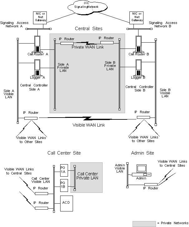
The Unified ICM system consists of a number of computers, or nodes, which are typically located at more than one site. You can distribute an Unified ICM system among three to fifty sites or more. Each site can contain one or more nodes. The Unified ICM system requires several networks to interconnect nodes within and among the sites.

There are three basic types of Unified ICM sites:

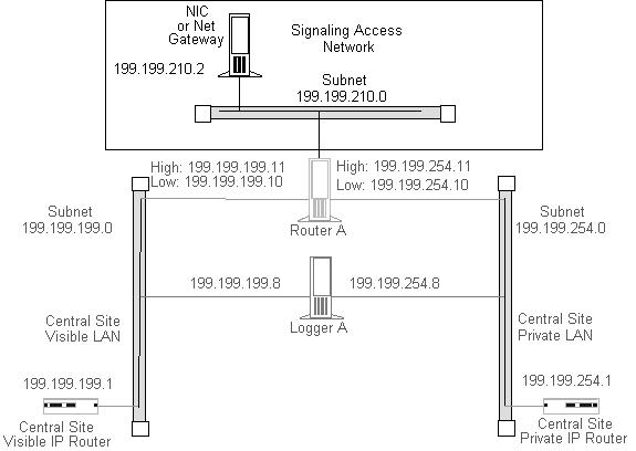
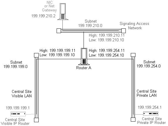
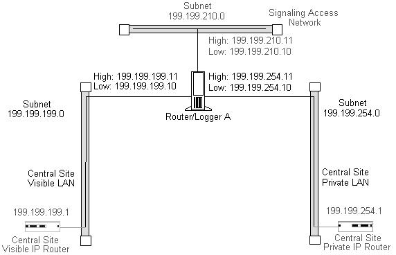
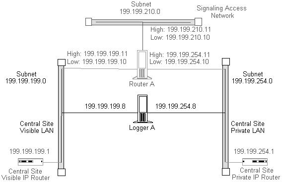
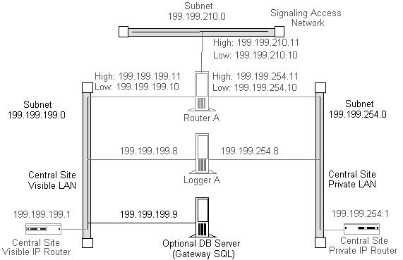
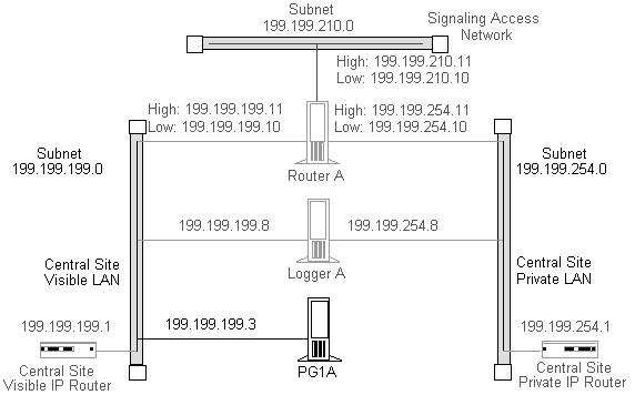
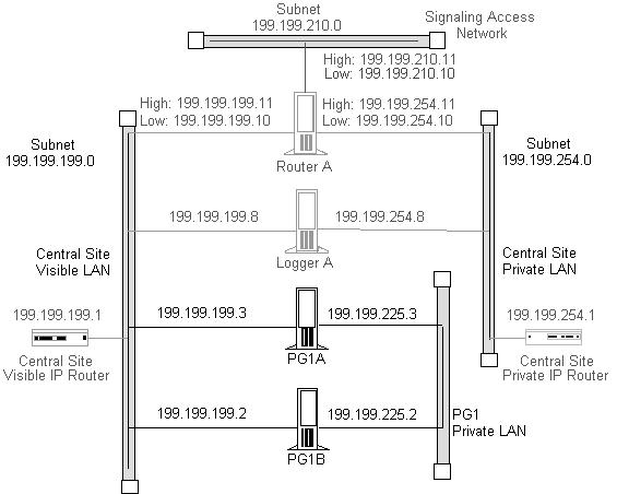
  • Central sites. Contain one or both sides of the central controller (that is, the CallRouter and Logger) and possibly a Network Gateway . Central sites can also contain Administration & Data Servers and Peripheral Gateways.

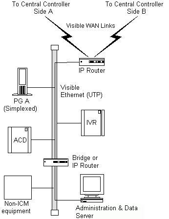
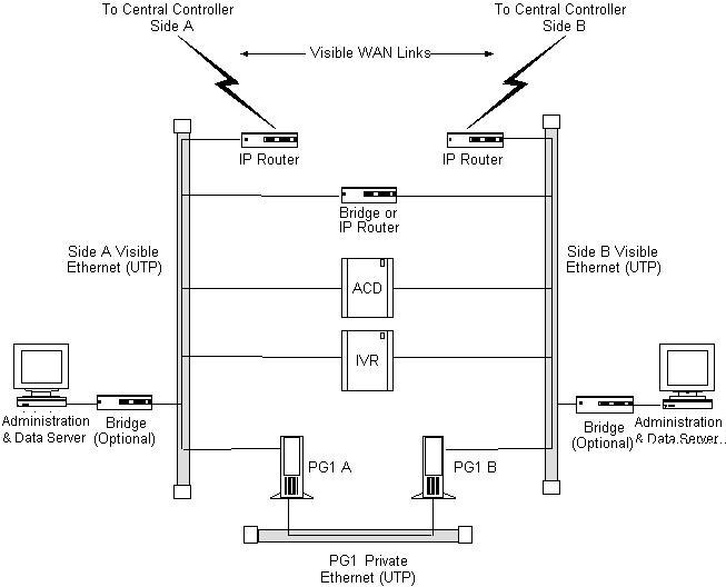
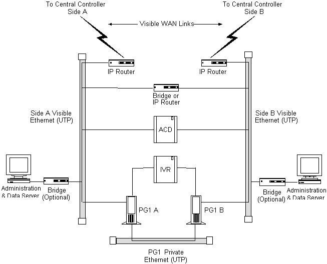
  • Contact center sites. Contain one or more Peripheral Gateways (PGs) and possibly Administration & Data Servers. Sites also support Agents, phone applications and CTI applications.

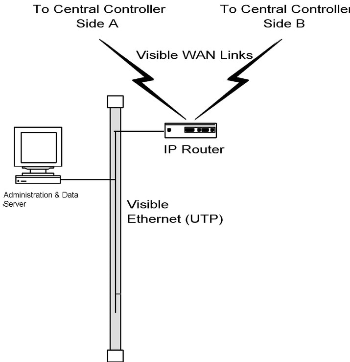
  • Admin sites. Contain one or more Administration & Data Servers.

An Unified ICM site can be a combination of any two or more of these. For example, a single location can be both a central site and a contact center site.

ICM Networks

Following are the three Unified ICM independent communications networks:

  • Private network. This is a dedicated network that allows specific nodes to communicate with each other without outside interference. This network carries the data that is necessary to maintain and restore synchronization between the systems. The private network is not used for any other purpose.

  • Visible network. This is a shared network that allows the central controller to communicate with local and remote nodes. It carries traffic between each side of the synchronized system and foreign systems. The fault tolerance software can use the visible network as an alternate network to distinguish between node failures and network failures.

  • Signaling Access Network. This network connects the Unified ICM system to a carrier network or client network. When a SAN is implemented, the Unified ICM system uses the SAN (not the private network) to communicate with the carrier network.

The following figure shows the two sides of the central controller, a contact center site, and an administrator site. A private WAN links both sides of the duplexed central controller. A visible WAN links the contact center and administrator sites to each side of the central controller. Nodes within each site are linked by a local area network (LAN).

Figure 1. ICM System Network Overview

In the preceding figure, the two sides of the central controller are geographically separated. The wide area network connections in both the private and visible networks are referred to as WAN links. WAN links in the Unified ICM system are typically high-availability provisioned circuits. These links must possess extremely low and extremely predictable latency characteristics. Therefore, you cannot use some types of WAN service for WAN links within the Unified ICM system (for example, packet routing).

Private and Visible WAN Links

The two sides of the duplexed Unified ICM central controller share a single private network and are linked via a private WAN link. They also share a visible network which connects the two sides via a visible WAN link. To ensure a high level of fault tolerance, the private WAN link and visible WAN links must be independent (that is, they must use different trunks and possibly even different service providers).

When the two sides of the central controller are co-located, you do not need the visible WAN link between the sites. The standard visible WAN links to remote contact center sites provide adequate connectivity between the two sides. In a co-located central controller configuration, you use Ethernet switches to implement the private network locally.

Remote contact centers connect to each side of the central controller via the visible network. Each visible WAN link to a contact center must have adequate bandwidth to support PGs and Administration & Data Servers at the contact center (the bandwidth requirement varies greatly as the configuration changes, that is, the call load, the number of agents, and so on).

When a contact center is co-located with a side of the central controller, the PGs and Administration & Data Servers connect to the visible LAN on that side. The PGs and Administration & Data Servers connect to the other side of the central controller via a visible WAN link. In such a configuration, you need a direct visible WAN link between the sides of the central controller to ensure adequate connectivity between the two sides. You may optionally deploy LAN bridges to isolate PGs from the Administration & Data Server LAN segment and to enhance protection against LAN outages.


Note

See the section titled Central Site Visible Network, for some examples of co-located central controller configurations.

Signaling Access Networking

The CallRouter machine connects to the IXC signaling network via the Signaling Access Network (SAN). A separate LAN interface card in the CallRouter is dedicated for use just by the SAN. The SAN connects the NICs on each side of the duplexed system to the IXC signaling network. In most cases, the NIC software runs on the CallRouter computer. For clarity, in ICM Networks, the NIC is shown as a separate computer installed on the SAN.

You can install a node called the Unified ICM Network Gateway on the SAN to interface to some Sigtran-based networks. The Unified ICM Network Gateway is a dedicated machine that provides Sigtran protocol handling services.

In Sigtran networks, you can co-locate Sigtran Gateways on the CallRouter machine or on a separate machine. However, the INAP Sigtran gateway must be installed on a seperate machine. Sigtran Gateways connect to the Sigtran network using the SCCP User Adaptation layer (SUA) with Stream Control Transmission Protocol (SCTP) as the network transport. Sigtran Gateways can serve the following functions, depending on customer requirements:

  • Communicate with the Service Switching Point (SSP)

  • Communicate with the Media Gateway Controller

  • Communicate directly to a Signaling Gateway. In this deployment Sigtran connections are established using a Client / Server message exchange, in which the Sigtran Client requests connections with the Sigtran Server. The Signaling Gateway (such as Cisco's Internet Transfer Point) is a server in this model and accepts incoming connection requests. The Sigtran Gateways act as the Client when connected to a Signaling Gateway.

Network Topology

The Unified ICM system uses Ethernet for local area network connectivity. The particular Ethernet topology used is immaterial from an architectural standpoint. However, the topology used may be relevant from a network or systems management perspective. Typically, UTP is used in the private, visible, and signaling access LANs.

The three networks (visible, private, and signaling) should be on separate LAN segments. This requires the use of three Ethernet cards in the CallRouter machine.

Network Bandwidth Requirements

The visible network bandwidth requirements for a typical Unified ICM system are about 1,000 bytes of data per call over the networks that carry call data. For example, if a remote PG is managing 15 calls per second at a contact center site, it needs to transfer 15,000 bytes of data over the visible WAN to the central site every second (a total of 120,000 bits per second, ignoring packet overhead).

The bandwidth for the private WAN between the two sides of a duplexed central controller must support the total sustained call load for all ACD sites. In addition, bandwidth on this private WAN must provide some degree of burst resilience and enough reserve capacity to perform fault tolerant messaging and synchronization. The following table summarizes the network circuit requirements for visible and private networks within the Unified ICM system.

Table 1. Network circuit requirements

Network

Purpose

Facilities

Min. Bandwidth

Private WAN

Dedicated path that connects both sides of a duplexed, distributed ICM central controller.

Ethernet Unshielded Twisted Pair (UTP)

128-Kbps dedicated.

Visible WAN

Circuits that connect PGs and Administration & Data Servers at remote sites to each side of the ICM central controller.

Ethernet Unshielded Twisted Pair (UTP)

128-Kbps dedicated.

Note 

Variable, depending on load. See the section Calculating QoS Bandwidth Requirements, page 11-11, for a means of calculating the minimum required bandwidth for a Quality of Service (QoS) compliant network.

Signaling Access Network

Local area network that connects the NIC to the IXC carrier network or client network.

Ethernet Unshielded Twisted Pair (UTP)

100 Mbps

Visible and private LANs

Local area networks that connect ICM nodes at a central site and PGs and Administration & Data Servers at remote contact center sites.

Ethernet Unshielded Twisted Pair (UTP). Cisco requires using manageable hubs.

1000 Mbps

Note 

Variable, depending on load. See the section Calculating QoS Bandwidth Requirements, page 11-11, for a means of calculating the minimum required bandwidth for a Quality of Service (QoS) compliant network.

You may require additional bandwidth on the visible WAN. The actual requirement depends on a number of factors, including call load, the number of ACDs, the number of agents, and the number of Admin sites.


Note

If your network is utilizing the Cisco Unified ICM Quality of Service (QoS) feature, see Cisco ICM Quality Of Service (QoS), for additional latency considerations.

Network Latency Requirements

The Unified ICM system is a real-time, fault-tolerant distributed system.

To guarantee the real-time nature of the system and to support the methods used in fault tolerance, the WAN links in the Unified ICM system must have low and predictable message latency characteristics, especially in these critical areas:

  • Route requests and route responses between the CallRouter/NIC and IXC. This communication must meet the strict message latency requirements of the carrier networks.

  • Communications involving post-routing requests from PGs and route responses from the CallRouter. This communication must also be fast because callers are online and expect an appropriate agent to answer the call.

  • Communications from the PGs to the CallRouter concerning the real-time status of the contact center. The CallRouter needs this information to base its routing decisions on the latest data available from the contact center.

Three fault tolerance mechanisms of the Unified ICM system require reliable, low latency communications. These mechanisms are heartbeat detection, synchronization, and state transfer.


Note

If your network uses the Cisco Unified ICM Quality of Service (QoS) feature, see Cisco ICM Quality Of Service (QoS), for additional latency considerations.

Heartbeat and Keepalive Detection

As part of its fault-tolerant design, the Unified ICM system must quickly respond when a component goes offline for any reason (typically, because of a failure in the node or in a network link).

Unified ICM uses the Message Delivery Subsystem (MDS) to send synchronization messages. The private network uses TCP keepalive messages that are generated at 100-ms intervals. If no TCP keepalive messages arrive for 500 ms, the system decides that either a network or component failure occurred.

The public network uses the UDP heartbeat mechanism between PGs and the Central Controller. Redundant components generate UDP heartbeats at 100-ms intervals. Routers and PGs generate UDP heartbeats at 400-ms intervals. In both cases, the system decides a failure occurred after missing five UDP heartbeats.

Table 2. Heartbeat Configuration

Node

Medium

Interval

AT&T NIC (or Network Gateway) to CallRouter

Signaling Access Network

200 milliseconds

CallRouter to CallRouter

Private network

100 milliseconds

PG to CallRouter

Visible network

400 milliseconds

PG to PG (if duplexed)

PG to PG (if duplexed) Private network

100 milliseconds

The two sides of a duplexed Unified ICM central controller periodically test each other to see if the other side is operating correctly. As shown in the above table, network latency from CallRouter-to-CallRouter over the private network must support round trip messaging of 100 milliseconds. If the bandwidth of the private network is not adequate, IP routers may need to fragment packets to prevent long messages (greater than 1,500 bytes). Such long messages can delay transmission of User Datagram Protocol (UDP) packets, which indicate that the other side of the central controller is still operating.


Note

A consistent heartbeat or keep-alive mechanism is enforced for both the public and private network interface. When QoS is enabled on the network interface, a TCP keep-alive message is sent; otherwise UDP heartbeats are retained.

Another requirement of fault tolerance is that messages cannot be released back to a NIC or PG until the other side of the central controller has acknowledged receipt of a copy of the message. Therefore, in order to meet the 200 millisecond response times established by the carrier networks, and to leave some margin for queuing, a 100 millisecond round trip requirement is established.

Heartbeats from a remote PG to the CallRouter must compete with other network traffic on the visible WAN.

Synchronization

In a duplexed central controller configuration, the private network allows the CallRouters and Loggers on each side to run in a synchronized fashion. This means that the CallRouter and Logger processes on each side of the system receive the same input and generate the same output.

To ensure synchronization, each message intended for the CallRouter or Logger is received by a Synchronizer process that runs on the CallRouter node. The Synchronizer forwards the message across the private network to the Synchronizer on the other side. The Synchronizers then remove any duplicates before passing the messages on to the CallRouter processes. If a message is intended for the Logger, the CallRouter passes it along.

Figure 2. Role of Synchronizers

The preceding figure shows how the Synchronizers combine input messages and send the messages in the same order to each side of the central controller. Both CallRouters receive the same input and generate the same output. The Synchronizers ensure that both sides of the central controller return identical destinations for the same call and write identical data to the databases.

State Transfer

The fault tolerance of the Unified ICM system enables nodes to restart after a failure. However, when a failed node restarts, the values of variables in its memory are out-of-date. Before returning the node to service, the Unified ICM system must copy the values from its peer on the other side to the recovering node. That is, it must transfer the state of the running machine to the recovering machine. This transfer takes place over the private network.

Note that such state transfers occur after the failure and restart of any synchronized MDS client: PG, Logger, CallRouter, and so on.

Diverse Facilities

The private WAN between central controllers (when the central controllers are geographically separated) and the visible WAN must be on separate facilities. They must use different circuits and different IP routers. As added protection, you may also want to use diverse routes or even different service providers for the private and visible WAN links. Otherwise, you run the risk of having a single network failure disable both the Unified ICM private and visible WANs.

For example, if the private WAN fails, or a visible WAN link to one side of the central controller fails, the Unified ICM system continues to route calls and function normally. However, if the private WAN and the visible WAN are on the same facilities and fail simultaneously, the fault tolerance of the system is compromised. In such a scenario, the failure of any single node on either side of the central controller interrupts system processing. By provisioning the private WAN and visible WAN on separate facilities, you eliminate this potential point of failure.

Active Directory Services

Microsoft Windows Active Directory provides a central repository for managing network resources. Unified ICM software uses Active Directory services to control users' access rights to perform setup, configuration, and reporting tasks. Active Directory services also grant permissions for different components of Unified ICM software to interact; for example, it grants permissions for a Distributor to read the Logger database.

Unified ICME supports the Windows Active Directory domain. Native mode is required. Unified ICM user configuration data is stored in Active Directory Organizational Units (OU).

For more information, see the Staging Guide for Cisco Unified ICM/Contact Center Enterprise at http://www.cisco.com/c/en/us/support/customer-collaboration/unified-contact-center-enterprise/products-installation-guides-list.html.

Configure TCP/IP

To set up IP addresses for Windows Server 2012 nodes, use the TCP/IP Properties dialog box.

Procedure

  • To display this dialog box, go to the Windows Server Start menu:

    1. Choose Control Panel > Network and Internet.

    2. Click Network and Sharing Center.

    3. Click Change Adapter Settings.

    4. Right-click the Local Adapter.

    5. Click Properties.

    6. Select Internet Protocol (TCP/IP) and click on Properties.

  • Select "Use the following IP address". Enter the IP address and click OK. To enter additional IP addresses, open the TCP/IP Properties window again and click Advanced. Enter additional IP addresses in the Advanced TCP/IP Settings window.

Central Sites

Each side of the central controller includes the CallRouter, Logger, and Network Interface Controller (NIC). These can be on three separate nodes, two nodes, or a single node. Although the NICs are indicated as separate nodes for clarity, a NIC is implemented as a process within the CallRouter node. The two sides of the central controller can be at two different central sites as shown in the following figure.

Figure 3. Geographically Distributed Central Controller
Two sides of the central

The private network carries Unified ICM system traffic between the nodes on one side of the central controller and between the nodes on both sides of the system. The traffic between the two sides of the central controller consists of synchronization and state transfer messaging between the CallRouters and Loggers. Most communications between the CallRouter and Logger on one side take place over the private network.

The private WAN link (see the preceding figure) is critical to the overall responsiveness of the Unified ICM system. First, it must provide sufficient bandwidth to handle simultaneous synchronizer and state transfer traffic. It must also have enough bandwidth left over to transfer more data as part of a recovery operation. The private WAN link is the only link that carries central controller synchronization and state transfer traffic, so you may want to provision backup service as a contingency for network outages.

The IP routers in the private network always use traffic prioritization. The IP routers in the private network frequently use IP fragmentation, to ensure that high priority Unified ICM system traffic does not experience excessive queuing delay. Alternately, you can co-locate both sides of the central controller at a single site as shown in the following figure.

Figure 4. Co-located Central Controller

In a co-located central controller configuration, Ethernet switches separate Side A, and Side B private Ethernet LANs for fault tolerance. This private network bridge replaces the private WAN link. A visible network bridge also connects the Side A, and Side B visible networks.

Central Site Visible Network

Each central site has a visible network that connects nodes within that site. To allow communication between sites, each side of the central controller must have one IP router on its visible LAN.


Note

When a Peripheral Gateway is co-located with one side of a duplexed, geographically distributed central controller, you must have a direct connection between the visible WAN IP routers at the two central sites. This ensures that there is adequate visible network connectivity between the sides of the central controller.

The IP router requires a single address on the LAN. It also requires that you define a static route on the IP router for each contact center's visible LAN and for each administrator site's visible LAN.

Visible IP Router Configuration

To allow optimal tuning of the network, Cisco requires that you use IP routers to prioritize packets based on a range of source or destination port numbers. Typically, you need to set up the IP router to give higher priority to certain outgoing network packets. Also, depending on the bandwidth available on the visible WAN, you may need to set up IP fragmentation. The table titled Central Site Visible IP Router Configuration summarizes the configuration for the visible network IP router.

Table 3. Central Site Visible IP Router Configuration

Attribute

Requirements

IP Addresses

One address required.

Default Gateway

The network bridge (or the IP router used as bridge), if any. Otherwise, the IP router does not have a default gateway.

Static Routes

Define one static route for the visible LAN at each remote contact center site and each administrator site. If the central sites are geographically separated, add a static route for the other central site.

Other

Turn off any preset routing protocols. Give higher priority to specific network packets. Use fragmentation if necessary to limit the queuing delay.

You may need to prioritize packets as described in the table titled Visible Network Packet Priorities from Central Site.

Table 4. Visible Network Packet Priorities from Central Site

Packet Type

High Priority

Low Priority

TCP

If received from the CallRouter’s high priority address (as derived from the packet’s source address).

If received from any other address.

UDP

If source or destination port number is in the range 39000–39999

All other UDP packets.

The maximum queuing delay is 50 milliseconds to contact center sites that use post-routing or translation routes and 200 milliseconds to other contact center sites. You may have to implement fragmentation to meet these limits.

Central Site Private Network

Each central site must also have its own private LAN. If the sides of the central controller are geographically separated, each private LAN has one IP router to communicate with the private WAN that connects the two sides.

If the two sides of the central controller are co-located, you do not need an IP router on the private LAN. If two central sites are geographically separated, each side requires an IP router on the private network.

The following table summarizes the configuration for the private network IP router.

Table 5. Central Site Private IP Router Configuration

Setting

Requirements

IP Addresses

None.

Default Gateway

Define one static route for the private LAN at the other central site.

Static Routes

Define one static route for the private LAN at the other central site.

Other

Turn off any preset routing protocols.

Give higher priority to specific network packets.

The following table describes how you must prioritize private network packets.

Table 6. Private Network Packet Priorities from Central Site

Packet Type

High Priority

Low Priority

TCP

If the source address is the local CallRouter's high priority address or the destination address is the other CallRouter's high priority address.

All other TCP packets.

UDP

If source or destination port number is in the range 39000–39999.

All other UDP packets.

Signaling Access Network

Each central site must have its own Signaling Access Network (SAN). The Unified ICM system uses the Signaling Access Network to communicate with the IXC signaling network.

The Signaling Access Network for the following NICs is implemented as an Ethernet LAN. This LAN is separate from the Unified ICM private LAN.

  • CRSP

  • ICRP

  • Nortel

  • NTL

The following figure shows a typical Signaling Access Network for a single central site. It assumes that the two sides are geographically separated.


Note

The IP addresses shown in this and subsequent figures are examples only. Use addresses specific to your networks.
Figure 5. Central Site Signaling Access Network


CallRouter Node

The CallRouter connects to the visible network through the visible LAN; and to the private network through the private LAN. The CallRouter also has a connection to the Signaling Access Network.

Figure 6. CallRouter Network Connections

As shown in the preceding figure, the CallRouter requires two addresses on the visible LAN, two addresses on the private LAN, and two addresses on the signaling access LAN. This allows the Unified ICM system to separate high-priority network traffic from low-priority traffic.

The following table summarizes the visible network configuration for the CallRouter.

Table 7. CallRouter Visible Network Configuration

Setting

Requirements

IP Addresses

Two required: one for high priority data, one for low (normal) priority data. Note that only one address is required if you are using QoS.

Default Gateway

Visible network IP router.

Static Routes

None.

Other

Preferred and alternate DNS server. See Active Directory Model, page 11-21.

The following table summarizes the private network configuration for the CallRouter.

Table 8. CallRouter Private Network Configuration

Setting

Requirements

IP Addresses

Two required: one for high priority data, one for low (normal) priority data.

Default Gateway

None. (The default gateway is on the visible LAN.)

Static Routes

If the sides of the central controller are geographically separated, define one static route for the subnet address of the private LAN on the other side of the central controller.

Other

Disable Windows Server 2012 R2 networking on the private LAN.


Note

Instructions on disabling Windows Server networking on the private LAN appear later in this section.

The following table summarizes the Signaling Access Network configuration for the CallRouter.

Table 9. CallRouter Signaling Access LAN Configuration

Setting

Requirements

IP Addresses

Two may be required, the second functioning as a serviceability interface for your Unified ICM service provider.

Default Gateway

None.

Static Routes

None.

Other

Disable Windows Server 2012 R2 networking on the private LAN.

Disabling Windows Server 2012 Networking

You must disable network bindings for the private LAN adaptor on machines that connect to the Unified ICM private network.

You can disable Windows Server 2012 networking on the private LAN interface through the Network and Dial-up Connections window. Right click on the My Network Places icon on the Windows Server 2012 desktop. The Network and Dial-up Connections window appears. (Optionally, you can right-click on the My Computer icon, select Explore, then right click on My Network Places and select Properties.) Choose Advanced > Advanced Settings to display the Advanced Settings window.

Make sure that the visible network connection appears first in the list, followed by the private network connection. You can change the order in which the network connections appear by using the arrows on the right side of the window. Select the private network connection and disable both "File and Printer Sharing for Microsoft Networks" and "Client for Microsoft Networks."

Logger Node

The Logger can be on the same node as the CallRouter, or it can be a separate node.

Figure 7. CallRouter and Logger Combination
If the CallRouter and Logger are on the same node, then the Logger has no specific requirements; it uses low priority addresses defined for the node on the visible and private networks. If the two are on separate nodes, then the Logger requires its own connections to both the visible and private LANs.
Figure 8. Logger as a Separate Node


In addition to the IP addresses shown, the Logger node may require two additional addresses on the visible network. These addresses allow for dial-in connections by your Unified ICM support provider's Distributed Diagnostic and Service Network (DDSN). The following table summarizes the visible network connections for the Logger.

Table 10. Logger Visible Network Configuration

Setting

Requirements

IP Addresses

Three addresses may be required: one for normal data, two more for DDSN dial-up connections.

Default Gateway

Visible network IP router.

Static Routes

None.

Other

Preferred and alternate DNS server. See Active Directory Services.

The following table summarizes the private network configuration for the Logger.

Table 11. Logger Private Network Configuration

Setting

Requirements

IP Addresses

One address required.

Default Gateway

None. (The default gateway is on the visible LAN.)

Static Routes

If the two sides of the central controller are geographically separated, define one static route for the subnet address of the private LAN for the other side of the central controller.

Other

Disable Windows Server 2012 networking on the private LAN interface. (See Disabling Windows Server 2012 Networking for more information.)

If the Logger is on the same computer as the CallRouter, then the visible and private network IP configuration for the CallRouter is all that is required.

If the Logger is a separate node, you must disable networking on the private LAN interface (as was required for the CallRouter).

Define a static route in ICMEXEC.BAT, as for the CallRouter.

Optional Database Server Platform

If you deploy the Cisco Unified ICM Gateway SQL option, you must set up an additional Microsoft SQL Server database platform. The database server requires one IP address and one connection to the Unified ICM visible network.

Figure 9. Optional Database Server

You can deploy an Unified ICM Network Gateway on the Signaling Access Network in Sigtran network environments. The Unified ICM Network Gateway is a dedicated Windows Server machine that provides Sigtran protocol handling. When you use an Unified ICM Network Gateway, you install the NIC software on the CallRouter machine and use a separate Gateway machine as the interface between the CallRouter and the carrier's Sigtran signaling network.

You install the Network Gateway on a dedicated machine. It connects to both the Signaling Access Network (SAN) and to the Unified ICM visible network. You use the visible network connection strictly for management and maintenance. The Unified ICM Network Gateway does not connect to other nodes at the central site or to nodes at other sites. For example, it does not communicate over the private network with a network gateway on the other side of the system.

The Unified ICM Network Gateway can support up to sixteen signaling links to the IXC signaling network.

In Sigtran networks you can deploy a Sigtran Gateway on either the CallRouter machine or on a separate machine. This Sigtran Gateway can communicate with either a Service Switching Point or a Media Gateway Controller, or it can communicate directly with a Signaling Gateway. In this deployment, a Client / Server message exchange establishes Sigtran connections, in which the Sigtran Client requests connections with the Sigtran Server. The Signaling Gateway (such as Cisco's Internet Transfer Point) is a server in this model and accepts incoming connection requests. The Sigtran Gateways act as the Client when connected to a Signaling Gateway.

The following table summarizes the Signaling Access Network requirements for an Unified ICM Network Gateway.

Table 12. ICM Network Gateway Signaling Access Network configuration

Setting

Requirements

IP Addresses

One address required.

Default Gateway

None.

Static Routes

None.

Other

A HOSTS file is set up and changes are made to the CONFIG.SYS and AUTOEXEC.BAT files. Consult with your ICM support provider before changing these settings.

The following table summarizes the visible network requirements for an Unified ICM Network Gateway.

Table 13. ICM Network Gateway Visible Network configuration

Setting

Requirements

IP Addresses

One address required.

Default Gateway

Visible network IP router.

Static Routes

None.

Other

A HOSTS file is set up and changes are made to the CONFIG.SYS and AUTOEXEC.BAT files. Consult with your Unified ICM support provider before changing these settings.

Administration and Data Servers at Central Site

Cisco requires that you use Ethernet switches to isolate the CallRouter, Logger, and PGs from the Administration & Data Server LAN segment. This requirement limits the impact of one network's problems on another. Isolate the central controller and PGs from the Administration & Data Server LAN segment, to protect critical components from network hardware and software failures. For example, you can protect components from failures such as an open Ethernet tap or a network error burst.

For further protection against LAN outages, use an IP router instead of a bridge. You can then place the Administration & Data Server on a separate LAN with other contact center computers and applications. The IP router is a preferable option in this situation. LAN bridges tend to forward network error bursts from one side of a LAN to the other. IP routers provide an enhanced firewall because they do not forward network errors to other LANs.

The Administration & Data Server must reside on a network visible to the Unified ICM software. The following figure shows how you can use a LAN bridge or an IP router to isolate PGs and the central controller from the Administration & Data Server LAN segment.

Figure 10. Administration & Data Server at a Central Site


Peripheral Gateways at Central Site

A Peripheral Gateway (PG) that is co-located with one or both sides of the central controller can share the same visible LAN segment as the CallRouter and Logger nodes. The PG can communicate with the local CallRouter through the visible LAN. If the sides of the central controller are geographically separated, the PG communicates with the other side through the visible IP router and a WAN link. (If both sides of the central controller are co-located with the PG, then the PG communicates with both sides through the visible LAN.)

The following figure shows the network connection for a PG at a central site.

Figure 11. Peripheral Gateway at a Central Site

The ACD itself can also be on the visible LAN.

If the PG is duplexed, then you must connect the two duplexed PGs through a separate private network. (They cannot use the same private network as the CallRouter and Logger.) See the following figure.

Figure 12. Duplexed Peripheral Gateways at a Central Site

If you have more than one pair of duplexed PGs at a site, each pair requires its own private LAN. The private LAN for the PGs allows for synchronization and state transfer between the PGs. It is not used for any other purpose.


Note

When a Peripheral Gateway is located with one side of a geographically distributed central controller, you must have a WAN link directly connecting the visible WAN IP routers at the two central sites. This ensures that there is adequate visible network connectivity between the sides of the central controller. For more information on PG networking requirements, see the next section, "Contact Center Sites".

Contact Center Sites

Each contact center site includes at least one ACD, at least one Peripheral Gateway (PG), and optionally, one or more Administration & Data Servers. Contact centers can also have an Interactive Voice Response (IVR) unit. For fault-tolerance, the contact center site must include a duplexed pair of PGs.

A remote contact center complex is reached via the visible network, often with multiple access paths and through multiple IP routers. The contact center site must have at least one IP router on the visible network to communicate with the central controller. For maximum fault-tolerance, the site should have two IP routers, each connecting to one side of the central controller.


Note

For information on installing and configuring the Unified ICM Peripheral Gateway software, see the Pre-installation Planning Guide for Cisco Unified ICM at http://www.cisco.com/c/en/us/support/customer-collaboration/unified-contact-center-enterprise/products-installation-guides-list.html.

Simplexed PG Site

The following figure shows one option for a contact center configuration with a simplexed PG and an Administration & Data Server. This site contains an ACD and an VRU system. You can install the VRU PG software and the ACD PG software on the same server hardware platform.

Figure 13. Contact Center with Simplexed PG

As shown in the preceding figure, the PG and Administration & Data Server share a single Ethernet LAN and an IP router. The IP router uses prioritization and IP fragmentation to minimize queuing delays for high-priority Unified ICM system traffic. Cisco requires that you separate the PG, ACD, VRU, and IP router from other devices by a bridge or IP router. This isolates the critical Unified ICM components from outages that other equipment and networks can cause.

The contact center example shown in the preceding figure is a low fault tolerance configuration. It is only for non-fault tolerant sites (for example, for contact center sites with one PG or administrator sites with Administration & Data Servers only). A simplexed PG configuration can represent a single point of failure. Loss of the only PG stops the flow of real-time data from the contact center to the CallRouter and prevents the use of post-routing and translation routes. You can protect against possible failures by using duplexed PGs.

Duplexed PG Site

A duplexed PG configuration provides enhanced fault-tolerance.

Figure 14. Fault Tolerant Contact Center

Note

A PG private LAN is added to allow direct communication between the two PGs. If you have more than one duplexed pair of PGs at a site, each PG pair requires its own private LAN. However, this requirement is slightly relaxed for Unified CCE in a Clustering over the Wan deployment model. For details, see the Solution Design Guide for Cisco Unified Contact Center Enterprise .

To further enhance the fault-tolerance of the contact center, you can configure each PG with its own visible LAN and IP router. This eliminates the LAN as a single point of failure. Each PG communicates with one side of the central controller using its own LAN and IP router.

If you used a single IP router instead of two, you introduce a potential single point of failure to the contact center site. Loss of the one IP router stops the flow of real-time data from the contact center to the CallRouter and stops the flow of monitoring data from the central controller to the Administration & Data Server. It also prevents the use of post-routing and translation routes for this contact center.

One of the two IP routers shown in the preceding figure serves as the default gateway for the PG. By default, the PG communicates with that side of the central controller. The PG must have a static route defined to the other side of the central controller through the other IP router.

Each PG can contain a modem to allow dial-in access through your Unified ICM support provider's Distributed Diagnostic and Service Network (DDSN). In addition to its normal address on the visible network, the PG then requires two additional visible LAN addresses for this dial-in access.

Duplexed PG Site with Separate IVR LAN

You can use another contact center configuration in cases where you need to separate IVR systems due to security concerns or when you must protect the management of the IVRs. The following figure shows an example of such a fault tolerant contact center site.

Figure 15. Fault Tolerant Contact Center—IVR on Separate LAN

With this option, the ACD is on the visible LAN under the assumption that another CTI application needs to interface to the ACD. An alternative is to have the ACD on the same LAN as the IVR system.

PG Network Configuration

The following table summarizes the network configuration for a simplexed PG.

Table 14. Simplexed PG Network Configuration

Setting

Requirements

IP Addresses

Three addresses may be required on the visible LAN: one for normal data and two for use by the DDSN.

Default Gateway

Define one of the visible network IP routers as the default gateway for the PG.

Static Routes

Define one static route to the visible LAN at the central site that is not targeted by the default gateway IP router.

Other

Preferred and alternate DNS server. See Active Directory Services.

The following table summarizes the network configuration for a duplexed PG.

Table 15. Duplexed PG Network Configuration

Setting

Requirements

IP Addresses

Each PG may require three addresses on the visible LAN (one for normal traffic plus two addresses for DDSN dial-up connections) and two addresses on the private LAN (one for high priority and one for low priority data).

Note 

For Enterprise versions, configure only one IP address on the PG-visible NIC. IP addresses for DDSN dial-up connections are for Hosted versions only.

Default Gateway

Define one of the visible network IP routers as the default gateway for each PG. Do not use the same IP router as the default gateway for both PGs.

Static Routes

Each PG requires a static route to the side of the central controller that is not targeted by its default gateway IP router.

Other

Preferred and alternate DNS server. See Active Directory Services.


Note

For more information on how Peripheral Gateways connect to ACDs, see Peripheral Gateway Configurations.

Contact Center IP Routers

The IP router requires a single address on the LAN. It also requires that you define a static route on the IP router to the side of the central controller (central site visible LAN) that is not targeted by the PG default gateway IP router.

To allow optimal tuning of the network, Cisco requires that you use IP routers to prioritize packets based on a range of source or destination port numbers. Typically, you need to set up the IP router to give higher priority to certain outgoing network packets. Also, depending on the bandwidth available on the visible WAN, you may need to set up IP fragmentation.

The following table summarizes the configuration for the IP routers.

Table 16. Contact center IP Router Configuration

Setting

Requirements

IP Addresses

Each IP router requires one address on the visible LAN.

Default Gateway

Network bridge or IP router used as bridge, if any. Otherwise, the IP router does not have a default gateway.

Static Routes

Each IP router must have a static route to reach one central site visible LAN.

Other

Turn off any preset routing protocols. Give higher priority to specific network packets. Use fragmentation if necessary to limit the queuing delay.


Note

The following table summarizes information about packet priorities.
Table 17. Contact Center Packet Priorities

Packet Type

High Priority

Low Priority

TCP

If sending to the CallRouter's high priority address (as derived from the packet's destination address).

If sending to any other address.

UDP

If source or destination port number is in the range 39000–39999.

All other UDP packets.

The maximum queuing delay is 50 milliseconds if the site uses post-routing or translation routes; 200 milliseconds otherwise. You may have to set up fragmentation to meet these limits.

Admin Sites

An administrator site contains one or more Administration & Data Servers. Each administrator site must have a visible LAN and an IP router to communicate with the central sites. An administrator site does not require a private LAN.

Figure 16. Admin Site Configuration

You can have multiple Administration & Data Servers on a single LAN.