Client ICM Configuration
This section provides instructions for the configuration tasks you must perform on the Client ICM.
The documentation set for this product strives to use bias-free language. For the purposes of this documentation set, bias-free is defined as language that does not imply discrimination based on age, disability, gender, racial identity, ethnic identity, sexual orientation, socioeconomic status, and intersectionality. Exceptions may be present in the documentation due to language that is hardcoded in the user interfaces of the product software, language used based on RFP documentation, or language that is used by a referenced third-party product. Learn more about how Cisco is using Inclusive Language.
This chapter includes instructions for the tasks you must perform on the client and server systems to configure the ICM-to-ICM correctly.
For the Client ICM, these tasks include the following:
Configuring an ICM Gateway process on the CallRouter.
Making the necessary script changes for sending pre-route or post-route requests to the Server ICM.
Optionally, specifying a fixed local port number for the Network CIC process.
For the Server ICM, these tasks include the following:
Installing and Configuring an INCRP NIC on the CallRouter.
Setting up the necessary translation route labels.
Making the necessary script changes for returning calls and labels to the Client ICM.
 Note |
If you are implementing a bidirectional ICM-to-ICM Gateway link (see the section, ICM-to-ICM Gateway Overview), perform Client and Server tasks on both Unified CCE instances. |
This section provides instructions for the configuration tasks you must perform on the Client ICM.
To identify the ICM Gateway Client for the ICM Gateway Server, run a full Web Setup Tool on the Client Router machine.
Note |
For more information on CallRouter installation, refer to the Installation Guide for Cisco Unified ICM/Contact Center Enterprise & Hosted. |
| Step 1 |
In the Router Properties screen, check the Remote Network Routing option box. |
| Step 2 |
Use the NAM ID field to specify a Client ICM ID number.
|
Note |
Make a note of this Client ICM ID number and use the same number for the Client ID setting in the Server ICM configuration. |
In a "side-by-side" architecture such as this, the Client ICM system requires only a subset of the normal ICM configuration data. The following table summarizes the configuration data for a Client ICM.
|
Table |
Contents |
|---|---|
|
Announcement |
Any announcements used in Client ICM scripts. |
|
Application Gateway |
A remote ICM gateway for each instance on each associated Server ICM. |
|
Business Entity |
The default business entity only. |
|
Call Type |
Typically, one for each instance. |
|
Call Type Map |
Associate each Client ICM call type with a Client ICM script. |
|
Dialed Number |
All dialed numbers used on associated Server ICMs, plus the numbers used for direct translation. (No default routes are defined for Client ICM dialed numbers.) |
|
Dialed Number Map |
Associates dialed numbers and calling line IDs with Client ICM call types. |
|
Label |
All labels returned by associated Server ICMs, plus the labels used for direct translation. |
|
Network Interface Controller |
One required for the Network Interface Controller to the carrier network. |
|
Peripheral Gateway (PG) |
One or more for the Peripheral Gateway to the carrier network. |
|
Prefix |
Any prefixes used in Client ICM regions. |
|
Region |
Any regions used in Client ICM dialed number map. |
|
Routing Client |
One or more for the carrier network. |
|
Script |
One or more for each call type. |
The Client ICM needs only a limited configuration (dialed numbers, labels, basic routing scripts, and so on) while the instance-specific scripts, and the configuration, real-time, and historical data are stored on the Server ICM.
To set up your Client ICM configuration, run Configuration Manager on a Client ICM Admin Workstation.
Note |
For instructions on using Configuration Manager, refer to the Configuration Guide for Cisco Unified ICM/Contact Center Enterprise and Hosted. |
An Application Gateway process must be configured on the Client ICM for each Server ICM that the Client ICM is going to communicate with. To configure a new Application Gateway, perform the following steps.
| Step 1 |
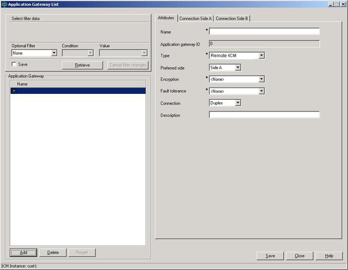
From the ICM Configuration Manager on an Admin Workstation associated with the Client ICM, select . The Application Gateway List window appears. |
||
| Step 2 |
Click Retrieve. |
||
| Step 3 |
Click
Add. The
Attributes tab appears. |
||
| Step 4 |
Specify the following values on the Attributes tab:
|
||
| Step 5 |
Click the Save button to create the gateway.
|
||
| Step 6 |
To set the connection information, click the Connection Side A tab or the Connection Side B tab. |
||
| Step 7 |
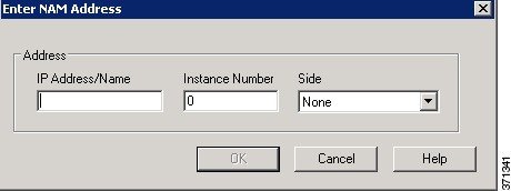
To specify an
address, click the
Enter
Address button. The Enter NAM Addresses dialog box appears.
|
||
| Step 8 |
Specify the following information: |
||
| Step 9 |
When finished, click Save to save the changes. |
||
| Step 10 |
From the Application Gateway list, make note of the Application Gateway IDs numbers for the server systems. You specify these Application Gateway ID numbers during Server-side configuration. |
The bottom half of the ConnectionSide A and Connection Side B tabs display several timeout and limit values. Accept the defaults for these values.
If the gateway process is already present on the CallRouter, perform the following steps to configure it for ICM-to-ICM Gateway use.
| Step 1 |
From the ICM
Configuration Manager on an Admin Workstation associated with the Client ICM,
select
screen.
|
||
| Step 2 |
Click Retrieve. |
||
| Step 3 |
From the Application Gateway list, make note of the Application Gateway IDs numbers for the server systems. You specify these Application Gateway ID numbers during Server-side configuration. |
||
| Step 4 |
Configure the Connection Side A and Connection Side B tabs as needed.
|
||
| Step 5 |
Navigate to Miscellaneous Tools > System Information in configuration manager. |
||
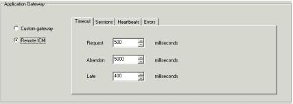
| Step 6 |
In the
Application Gateway section, click
Remote ICM.
Accept the default values for the remaining fields on all tabs.
|
Typically, the Client ICM originally receives the call and pre-routes it to an ACD. The call is then post-routed to a peripheral associated with the server system. The client determines the label associated with the server’s peripheral by requesting the label from an ICM Gateway node in a script.
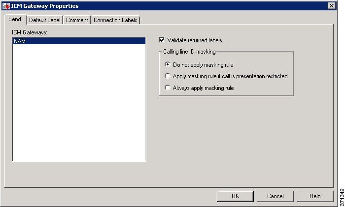
From the Script Editor, you can specify a local definition of the label that the ICM Gateway node returns. Perform the following steps:
| Step 1 |
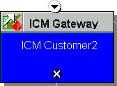
Right-click on
the ICM Gateway node. |
| Step 2 |
From the pop-up
menu that appears, choose
Properties. The ICM Gateway dialog box appears.
|
| Step 3 |
From the list, select the gateway to the Unified CCE to which you want to send the request. |
| Step 4 |
Check the Validate Returned Labels check box if you want the Client ICM to validate the label that the Server ICM returns before passing it to the routing client. If the Server ICM is returning a dynamic label, do not check this box. A dynamic label is an expression the Server ICM CallRouter converts to a character string and returns to the routing client as a label. |
| Step 5 |
On the Default Label tab, specify a default label to be used if the Server ICM returns an invalid label. |
| Step 6 |
Click OK. |
In an ICM-to-ICM Gateway implementation, the NetwrkCIC process is part of the Client CallRouter installation that manages the ICM Gateway. By default, the IP port used in the NetwrkCIC process for the public network communication to the Server ICM INCRP NIC process is selected dynamically at runtime.
Unified CCE processes use IP port numbers between 39000 and 50000. Use the following formula to obtain the number for side A of a duplexed system:
Port number = 40000 + (I * 40) + 33
where I is the instance number of an ICM instance. (NOTE: Typically, there is only a single instance for an ICM-to-ICM Gateway). To find the instance number, run the local setup program, select an instance, and click the edit button. The "Edit Instance" dialog box displays the instance number.
For instance number 0, the port number is 40033.
For side B, the port number is obtained by adding 1000 to the side A number. This formula is intended to be stable. However, there is no guarantee that the formula will not change.
If your site does not support dynamic port allocation, you can optionally modify the NetwrkCIC process to use a specific port number. To bind the NetwrkCIC process to a specific port number when communicating with the server INCRP NIC process, you specify the port number in the registry of the Client ICM machine.
To specify this port number, add the following registry entry on the Client ICM machine:
HKEY_LOCAL_MACHINE\SOFTWARE\Cisco Systems,
                                 		  Inc.\ICM\<instance name>\Router[A,B]\CIC\CurrentVersion\Configuration\CIC
                                 		  Public LAN IP Port
Specify the type of this entry as a DWORD.
Note |
The Web Setup Tool program does not manage this registry entry. If you upgrade Unified CCE, you must add the registry entry again. |
If the registry entry is not present, the NetwrkCIC process uses the port dynamically allocated as usual.
If you change the port number while the NetwrkCIC process is running, you must restart the CallRouter service for it to take effect.
For port usage details for the INCRP NIC, see the Port Utilization Guide for Cisco Unified Contact Center Solutions at https://www.cisco.com/c/en/us/support/customer-collaboration/unified-contact-center-enterprise/products-installation-and-configuration-guides-list.html.
This section provides instructions for the configuration tasks you must perform on the Server ICM.
Note |
The preferred network for this connection is the Public/Visible or SAN network. When using the SAN network, it must have a WAN link between Side A and B. SAN was originally intended for the CallRouter to Network Gateway connection, which does not cross the A/B boundary. |
| Step 1 |
Within the ICM Admin Workstation group, double-click Administration & Data Server. The Select Administration Client window appears. |
||
| Step 2 |
Select the instance you are configuring. |
||
| Step 3 |
From the ICM Configuration Manager, Configuration Manager > Tools > Explorer Tools > NIC Explorer. |
||
| Step 4 |
In the Select filter data box, click Retrieve. |
||
| Step 5 |
Click Add NIC. A new NIC and its routing client display in the tree window. Next to each is a To Be Inserted icon. On the right of the tree window, tabbed fields also display the new NIC's and routing client's configuration information. |
||
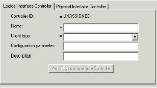
| Step 6 |
Enter the following in the Logical Interface Controller tab fields:
|
||
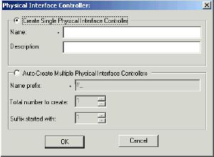
| Step 7 |
Click the
Add Physical
Interface Controller button. The Physical Interface Controller dialog box
appears.
|
||
| Step 8 |
In the Create Single Physical Interface Controller section, specify an Enterprise Name and, optionally, a Description.
|
||
| Step 9 |
Click OK. The Physical Interface Controller tab appears, displaying the information you specified, and an ID value of UNASSIGNED. |
||
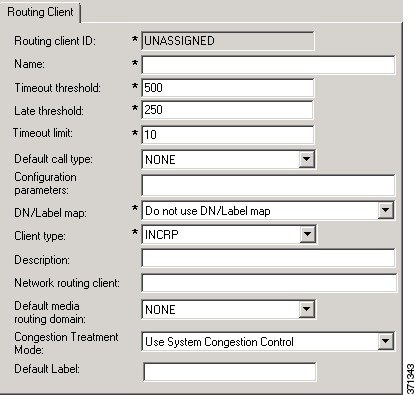
| Step 10 |
Enter the following information in the Routing Client tab fields:
|
||
| Step 11 |
Click Save. The newly defined NIC is saved in the database, a Physical Controller ID is assigned, and the To Be Inserted icon is removed from the tree window.
|
||
| Step 12 |
Click Close to exit the NIC Explorer. |
To configure the INCRP NIC on the Server ICM, run Web Setup Tool and edit the CallRouter from the Server Router machine (rather than from the installation CD).
Note |
For more information on CallRouter installation, refer to the Installation Guide for Cisco Unified ICM/Contact Center Enterprise & Hosted. |
Perform the following steps:
| Step 1 |
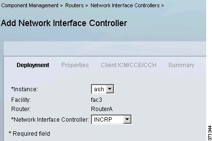
Run Web Setup Tool and select Component management > Routers > Network Interface Controllers. |
| Step 2 |
Click
Add Under
Deployment for the Added Instance. |
| Step 3 |
Set Network Interface Controller to INCRP. |
| Step 4 |
Click
Add. |
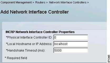
| Step 5 |
Complete the INCRP
Network Interface Controller Properties fields as configured for your system. Click
Next.
|
| Step 6 |
Complete the
Client ICM/CCE/CCH properties. Click
Next.
|
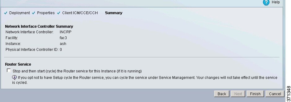
| Step 7 |
Click Finish. |
From the ICM-to-ICM Gateway server's point of view it is doing a translation route to one of its peripheral targets. When you set up a translation route on the Server ICM, set up a label for the original routing client providing a call to access each of the peripheral targets associated with the translation route. For example, if the routing client is an interexchange carrier (IXC), set up a label to the targets with the IXC. This method allows the call to be initially sent to the translation route at the peripheral.
Note |
For instructions on how to run Translation Route Wizard and how to define translation route labels, refer to the Configuration Guide for Cisco Unified ICM/Contact Center Enterprise and Hosted. |
The server requires a script that handles requests from the client. The script is associated with a call type, which is in turn defined by the dialed number, calling line id, and caller entered digits.
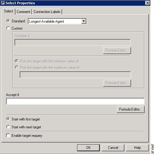
From the Script Editor, you can specify the label that the server script returns to the client. For example, you could create a Select node that routes calls to specified services under certain conditions. Perform the following steps.
| Step 1 |
From Script Editor, connect the Select node to a Service node. |
| Step 2 |
Right-click
the Select node and choose Properties. The dialog box appears.
|
| Step 3 |
Specify the criteria for selecting services. |
Note |
You can specify the label that the server script returns from other Script Editor nodes, such as the Label node. Refer to the Scripting and Media Routing Guide for Cisco Unified ICM/Contact Center Enterprise & Hosted for more information. |


 Feedback