Design Considerations

Principal Design Considerations for Call Center Sizing

This figure illustrates the principal steps and design considerations for sizing a call center.
Figure 1. Call Center Sizing - Voice Only

This figure is a general overview of the design considerations for call sizing. For a detailed description of the call center sizing design process, refer to the section on sizing call center resources in the Cisco Unified Contact Center Enterprise Solution Reference Network Design Guide, available online at the following URL:

http://www.cisco.com/go/ucsrnd

There are similar basic call center sizing considerations and steps for Unified CCE, and they also can be used in sizing a smaller contact center for Unified CCX. This call-sizing approach will provide you with the minimum number of IVR ports to support the total BHCA.

In addition, you should include the following design considerations, specific to Unified CCX, in your call center sizing calculations:
  • At a minimum, plan on enough capacity to replace your existing system. The replacement system should perform at least as well as the one it is replacing.

  • After all of the Erlang (C and B) calculations are complete for the call center sizing, any changes in queue times or agents will affect the total number of trunks and IVR ports required for an Unified CCX solution.

  • As you increase the size of the agent pool, very small changes in the average queue time and percentage of queued calls will affect the required number of gateway trunks and IVR ports.

  • Even if you perform all of the calculations for a call center, there are still some variables that you cannot plan for but that will affect the ports needed on a Unified CCX system. For example, one or more agents could call in sick, and that would affect the port count and queue time for each call. Just two agents calling in sick could increase the port count by over 12 percent. This would affect the price of the system and, if not planned for, would affect the ability of the call center to meet caller requirements. Properly sizing call center resources is integral to designing an effective Unified CCX system.

If all of the call sizing information is available, the next step is to apply Unified CCX sizing limits to the call center requirements. For this step, use the Cisco Unified Communications Sizing Tool, available online at:

http://tools.cisco.com/cucst

The Unified Communications downloadable sizing tools help you with the task of sizing Unified Communications deployments.

Preliminary Information Requirements

System designers are advised to create a sizing document to do the following:
  • Scope out the preliminary configuration information for the Unified CCX server.

  • Size the gateways for the system.

To determine the size of the call center, obtain answers to the following questions:
  • How many IVR ports do you need?

  • How many PSTN gateway trunk ports do you need?

  • How many agents will answer incoming calls?

To answer these questions properly, you will need the sizing metrics and information listed in the following table.
Table 1. Call Center Sizing Metrics

Metric

Description

Average handle time (AHT)

Average duration (talk time) of a call plus after-call work time, which is the wrap-up time after the caller hangs up.

Average IVR port usage time

The total time for prompt playout and/or menu navigation (if any) in the Unified CCX script. This time should not include the queue time the caller spends waiting in queue before an agent becomes available. Queue time is calculated using Erlang-C automatically.

Service level goal for agents

Percentage of calls answered by agents within a specific number of seconds.

Busy Hour Call Attempts (BHCA)

Average number of calls received in a busy hour.

Grade of service (% blockage) for gateway ports to the PSTN

Percentage of calls that get a busy tone (no gateway trunks available) out of the total BHCA.

All of the metrics in this table are basic call-sizing metrics. After this information is obtained, calculate the number of gateway trunk ports, IVR ports, and agents using standard Erlang B and C calculators.


Note

If the system being designed is a replacement for an existing ACD or an expansion to an installed Unified CCX or Cisco Unified IP IVR system, you might be able to use the historical reporting information from the existing system to arrive at the above metrics.


In addition, call sizing design considerations may vary if the call center is more self-service oriented.

Terminology

This figure illustrates the common port types and how they map to Unified CCX.

Figure 2. Call Center Port Types

Call center sizing differentiates the port types as follows:

  • Gateway or PSTN trunk ports — Handles calls originating from the PSTN. They are purchased separately from Unified CCX.

  • Queue ports — IVR ports that queue calls (when no agents are available) prior to transferring the caller to an available agent. These ports are included at no additional cost with Unified CCX Standard or Enhanced, but they must be sized for proper capacity planning for the Unified CCX server.

  • IVR ports — Full-featured IVR ports available with the Cisco Unified IP IVR and Unified CCX Premium product.

If you want additional supporting features, such as automatic speech recognition (ASR), text-to-speech (TTS), email notification, web server or client functionality, and database operations, you only need to purchase the Premium package. Additional seats may also be purchased for IVR port licenses if the number of port licenses that come with the seat licenses is not sufficient.

The Unified CCX architecture differs slightly from the example TDM call center configuration in that IVR ports and queue ports (and P&C ports as well) are combined into one logical CTI port as shown in the figure above.

Effect of Performance Criteria on Unified CCX Server

System performance criteria fall into two general categories:

  • Unified CCX and Cisco Unified IP IVR components — Applications, software versions, capabilities, server types, and options and quantities that your system requires.

  • System usage — The average number of calls placed and received per hour, the average call length, the scripts being executed, and the grammar used for ASR.

Effect of Performance Criteria

Each performance criterion can have an effect on the performance of the Unified CCX or Cisco Unified IP IVR system. In general, the more Unified CCX or Cisco Unified IP IVR components that you install and the heavier the system usage, the higher the demand on the server. However, the performance criteria can also interact in various non-linear ways to affect performance. The Cisco Unified Communications Sizing Tool for Unified CCX and Cisco Unified IP IVR can help you see and evaluate the effects of performance criteria on the Unified CCX and Cisco Unified IP IVR server.

Network latency between the following components affects the response time:

  • Media path between the end customer and the agent via SocialMiner.

  • Signaling path between the customer browser and Unified CCX via SocialMiner.

  • SocialMiner and mail servers like Exchange Server.

The customer chat interface retrieves updates in batches with a maximum delay of 5 seconds between batches.

Impact of Performance Criteria on the Unified CM Servers

Unified CM system performance is influenced by many criteria such as:
  • Software release versions— Using the Cisco Unified Communications sizing tool, make sure to select the Unified Communications Manager software version with which Unified CCX will be working.

  • The type and quantity of devices registered such as:

    • CTI ports (IP IVR ports for queuing, call treatment, and self-service)

    • Gateway (GW) ports

    • Agent phones

    • Route points

  • The load processed by these devices (calls per second)

  • Application call flows

    • IVR self-service

    • Call treatment/Prompt and collect

    • Routing to agents, % transfers and conferences

  • Special Unified Communications Manager configuration and services

    • Other non-Unified CCX devices—IP phones, GW ports, Unity ports, and dial plan.

    • Music on Hold (MOH)

    • Tracing levels— Unified Communications Manager CPU resource consumption varies depending on the trace level enabled. Changing trace level from Default to Full on Unified CM can increase CPU consumption significantly under high loads. Changing tracing level from Default to No tracing can also decrease CPU consumption significantly at high loads (this configuration is not supported by Cisco TAC). CPU consumption due to default trace will vary based on load, Unified Communications Manager release, applications installed, and call flow complexity.

  • Server platform type

Estimating Bandwidth Consumption

Bandwidth plays a large role in deployments involving:
  • The centralized call processing model (Unified CCX at the central site)

  • Any call deployment model that uses call admission control or a gatekeeper

  • Any deployments involving email processing model (via SocialMiner).

Remote Agent Traffic Profile

Unified CCX signaling represents only a very small portion of control traffic (Agent and Supervisor Desktop to and from the Unified CCX Server) in the network. For information on TCP ports and Differentiated Services Code Point (DSCP) marking for Unified CCX and CTI traffic.

Bandwidth estimation becomes an issue when voice is included in the calculation. Because WAN links are usually the lowest-speed circuits in an IP Telephony network, particular attention must be given to reducing packet loss, delay, and jitter where voice traffic is sent across these links. G.729 is the preferred codec for use over the WAN because the G.729 method for sampling audio introduces the least latency (only 30 milliseconds) in addition to any other delays caused by the network.

Where voice is included in bandwidth, system architects should consider the following factors:

  • Total delay budget for latency (taking into account WAN latency, serialization delays for any local area network traversed, and any forwarding latency present in the network devices). The generally agreed-upon limit for total (one-way) latency for applications in a network is 150 milliseconds.

  • Impact of delays inherent in the applications themselves. The average Unified CCX agent login time with no WAN delay is 8 seconds. This includes the exchange of approximately 1,000 messages between the agent application and various servers. The overall time to log in agents increases by approximately 30 seconds for each 30 milliseconds of WAN delay.

  • Impact of routing protocols. For example, Enhanced Interior Gateway Routing Protocol (EIGRP) uses quick convergence times and conservative use of bandwidth. EIGRP convergence also has a negligible impact on call processing and Unified CCX agent logins.

  • Method used for silently monitoring and recording agent calls. The method used dictates the bandwidth load on a given network link.

Use the following table to estimate the number of Unified CCX agents that can be maintained across the WAN (with IP Telephony QoS enabled). These numbers are derived from testing where an entire call session to Unified CCX agents, including G.729 RTP streams, is sent across the WAN. Approximately 30 percent of bandwidth is provisioned for voice. Voice drops are more of an issue when you are running RTP in conjunction with Cisco Finesse and other background traffic across the WAN. These voice drops might occur with a specific number of agents at a certain link speed, and those possible scenarios are denoted by the entry N/A (not applicable) in the following table.
Table 2. Remote Agents Supported by Unified CCX Across a WAN Link

Frame Relay

128 KB

256 KB

512 KB

768 KB

T1

G.729

3

7

15

25

38

G. 711

N/A

N/A

N/A

N/A

14

In remote agent deployments, QoS mechanisms should be used to optimize WAN bandwidth utilization. Advanced queuing and scheduling techniques should be used in distribution and core areas as well. For provisioning guidelines for centralized call processing deployments, refer to the Cisco IP Telephony Solution Reference Network Design documentation, available online at: http://www.cisco.com/go/ucsrnd.

IP Call Bandwidth Usage

An IP phone call consists of two streams of data. One stream is sent from phone A to phone B. The other stream is sent from phone B to phone A. The voice data is encapsulated into packets that are sent over the network. The amount of data required to store a voice stream is dependent upon the Codec used to encode the data.

The voice data itself is transmitted over the network using the Real-Time Transport Protocol (RTP). The RTP protocol supports silence suppression. When silence suppression is used, no voice packets are sent over the network if there is no sound.

Otherwise, even packets that contain silence are sent. This situation lowers the average required bandwidth for a call. Although it supports silence suppression, the lower bandwidth requirements for silence suppression should not be used when provisioning the network because the worst case scenario would be where there is not silence in the call, requiring the full call bandwidth as if silence suppression was not enabled.

When calculating bandwidth for an IP call, you must use the size of the RTP packet plus the additional overhead of the networking protocols used to transport the RTP data through the network.

For example, G.711 packets carrying 20 ms of speech data require 64 kbps (kilobytes per second) of network bandwidth per stream. These packets are encapsulated by four layers of networking protocols (RTP, UDP, IP, and Ethernet). Each of these protocols adds its own header information to the G.711 data. As a result, the G.711 data, once packed into an Ethernet frame, requires 87.2 kbps of bandwidth per data stream as it travels over the network. Because an IP phone call consists of two voice streams, in this example, a call would require 174.4 kbps.

The amount of voice data in a single packet also influences the size of the packet and bandwidth. The example above used packets containing 20 milliseconds of speech for its calculations, but this value can be changed in the Unified CM configuration for each supported Codec. Configuring packets to contain more speech information reduces the number of packets sent over the network and reduces the bandwidth because there are fewer packets containing the additional networking headers, but the packet sizes increase.

The following table shows the bandwidth required for a phone call for the different combinations of Codec and amount of speech per packet.
Table 3. Per-call Packet Size Bandwidth Requirements

Codec

Milliseconds of speech per packet

Bandwidth required (Kbps) for a call

G.711

10

220.8

G.711

20

174.4

G.711

30

159.0

G.729

10

108.8

G.729

20

62.4

G.729

30

47.0

G.729

40

39.2

G.729

50

34.6

G.729

60

31.4


Note

  • The calculations are based on G.711 using a sampling rate of 64 kbps speech encoding and the G.729 using 8 kbps. This means one second of speech encoded into the G.711 Codec requires 65,536 bits (or 8,192 bytes) to represent one second of sound.

  • For full-duplex connections, the bandwidth speed applies to both incoming and outgoing traffic. (For instance, for a 100-Mbps connection, there is 100 Mbps of upload bandwidth and 100 Mbps of download bandwidth.) Therefore, an IP phone call consumes the bandwidth equivalent of a single stream of data. In this scenario, a G.711 IP phone call with no silence suppression and containing 20 milliseconds of speech per packet requires 87.2 kbps (174.4 / 2) of the available bandwidth.

  • Unified CCX supports a-law and μ-law for G.711.

  • If a prompt is recorded with G711 a-law phones and uploaded, you may encounter an error while playing the recorded prompt.


Bandwidth Available for Monitoring and Recording

The following tables display the percentage of total bandwidth available, based on the network connection, which is required for simultaneous monitoring sessions handled by a VoIP provider.

Table 4. Available Upload Bandwidth Percentage for Simultaneous Monitoring Sessions with G.729 Codec

Number of Simultaneous Monitoring Sessions

Percentage of Available Bandwidth Required (No Silence Suppression)

100 Mbps

10 Mbps

1.544 Mbps

640 kbps

256 kbps

128 kbps

64 kbps

56 kbps

Call only

0.1

0.9

5.6

13.6

34.1

68.1

Not supported (NS)1

1

0.3

2.6

16.8

40.9

NS

NS

NS

NS

2

0.4

4.4

28.1

68.1

NS

NS

NS

NS

3

0.6

6.1

39.3

95.4

NS

NS

NS

NS

4

0.8

7.8

50.5

NS

NS

NS

NS

NS

5

1.0

9.6

61.7

NS

NS

NS

NS

NS

6

1.1

11.3

72.9

NS

NS

NS

NS

NS

7

1.3

13.1

84.2

NS

NS

NS

NS

NS

8

1.5

14.8

95.4

NS

NS

NS

NS

NS

9

1.7

16.6

NS

NS

NS

NS

NS

NS

10

1.8

18.3

NS

NS

NS

NS

NS

NS

1 The bandwidth of the connection is not large enough to support the number of simultaneous monitoring sessions.
Table 5. Available Upload Bandwidth Percentage for Simultaneous Monitoring Sessions with G.711 Codec

Number of Simultaneous Monitoring Sessions

Percentage of Available Bandwidth Required (No Silence Suppression)

100 Mbps

10 Mbps

1.544 Mbps

640 kbps

256 kbps

128 kbps

64 kbps

Call only

0.0

0.3

2.0

4.9

12.2

24.4

48.8

1

0.1

0.9

6.0

14.6

36.6

73.1

Not supported (NS)2

2

0.2

1.6

10.0

24.4

60.9

NS

NS

3

0.2

2.2

14.1

34.1

85.3

NS

NS

4

0.3

2.8

18.1

43.9

NS

NS

NS

5

0.3

3.4

22.1

53.6

NS

NS

NS

6

0.4

4.1

26.1

63.4

NS

NS

NS

7

0.5

4.7

30.1

73.1

NS

NS

NS

8

0.5

5.3

34.1

82.9

NS

NS

NS

9

0.6

5.9

38.1

92.6

NS

NS

NS

10

0.7

6.6

42.2

NS

NS

NS

NS

2 The bandwidth of the connection is not large enough to support the number of simultaneous monitoring sessions.
The following notes apply to the bandwidth requirements shown in the previous tables:
  • The bandwidth values are calculated based on the best speed of the indicated connections. A connection's true speed can differ from the maximum stated due to various factors.

  • The bandwidth requirements are based on upload speed. Download speed affects only the incoming stream for the IP phone call.

  • The values are based upon each voice packet containing 20 milliseconds of speech.

  • The number of bytes in each packet include the entire Ethernet encapsulation.

  • The data represents the Codecs without silence suppression. With silence suppression, the amount of bandwidth used may be lower.

  • The data shown does not address the quality of the speech of the monitored call. If the bandwidth requirements approach the total bandwidth available and other applications must share access to the network, latency (packet delay) of the voice packets can affect the quality of the monitored speech. However, latency does not affect the quality of recorded speech.

  • The data represents only the bandwidth required for monitoring and recording. It does not include the bandwidth requirements for Cisco Finesse.

Web Chat Feature

When deploying the Unified CCX along with Cisco SocialMiner, observe the following network requirements:

Delay—The maximum allowed round-trip time (RTT) between the Unified CCX server and SocialMiner is 150 ms.

Bandwidth—In addition to the requirements for the Unified CCX and Unified CM clusters, provision sufficient bandwidth for SocialMiner, the customer web server, and remote agent or supervisor desktops to deploy Web Chat successfully.

Consider the bandwidth required for the following components:

  • Unified CCX and SocialMiner—If SocialMiner and the Unified CCX are not co-located, there is an additional bandwidth requirement for the communication and contact signaling.

  • SocialMiner and Cisco Finesse Agent Desktop—When a chat session starts, depending on the chat transcript size and communication frequency, there is an additional bandwidth requirement between SocialMiner and the Cisco Finesse Agent Desktop.

  • SocialMiner and Customer Website—The customer website transfers all new chat contact requests to SocialMiner. When a chat contact request reaches SocialMiner, an active chat session is maintained by SocialMiner to carry chat messages between SocialMiner and the browser. After the chat contact request is transferred to SocialMiner, the customer website server is no longer a part of the active chat session.

The following table shows the minimum bandwidth requirement for the Unified CCX and SocialMiner when they are not located in the same network.


Note

These numbers depend on overall network efficiency.


Between Unified CCX and SocialMiner (KBps)

Between Unified CCX and Agent Desktop (KBps)

Between SocialMiner and Agent Desktop (KBps)

Between Customer Web Server and SocialMiner (KBps)

Actual data bandwidth

3.35 1

4.02 2

12 3

12 3

Data bandwidth considering HTTP traffic and other factors

40

40

100

100

1 Allocate network bandwidth for signal communication based on this formula:

Signaling network bandwidth (in KBps) = Number of new chat sessions per second × Number of messages per chat session × Average message size

Example

If you have a Busy Hour Call Completion (BHCC) of 2400 (maximum supported) with an average chat duration of 3 minutes, you have 0.67 chat sessions per second. On average, if each chat session has five messages for state signaling and contact injection and each message is 1 KB (500 characters), then bandwidth utilization is 0.67 × 5 ×1 KBps = 3.35 KBps.

2 Allocate network bandwidth for signal communication based on this formula:

Signaling network bandwidth (in KBps) = Number of new chat sessions per second × Number of messages per chat session × Average message size

Example

If you have a BHCC of 2400 (maximum supported) with an average chat duration of 3 minutes, you will have 0.67 chat sessions per second. On average, if each chat session has 3 messages and each message is 2 KB (1000 characters), bandwidth utilization is 0.67 × 3 × 2 KBps = 4.02 KBps.

3 Allocate network bandwidth for chat based on this formula:

Chat network bandwidth (in KBps) = Chat sessions sending message per second × Average message size

Example

If all of the120 sessions are active and 10 percent of the chat sessions are sending messages every second, 120 × 10 / 100 = 12 chat sessions are sending a message each second.

If the average message size is 1 KB (500 characters), the chat network bandwidth is 12 KBps.

Agent Email Feature

When you deploy Unified CCX along with Cisco SocialMiner, observe the following network requirements:

Delay—The maximum allowed round-trip time (RTT) between the Unified CCX server and SocialMiner is 150 ms.

Bandwidth—In addition to the requirements for the Unified CCX and Unified Communications Manager clusters, you must provision sufficient bandwidth for SocialMiner, the mail server, and remote agent/supervisor desktops to deploy Agent Email successfully.

The following table shows the minimum bandwidth requirement for Unified CCX and SocialMiner when they are not located in the same network.


Note

These numbers depend on overall network efficiency.


Between Unified CCX and SocialMiner (KBps)

Actual data bandwidth

0.67 1

Data bandwidth considering HTTP traffic and other factors

40

1 Allocate network bandwidth for signal communication based on this formula:

Signaling network bandwidth (in KBps) = Number of new email sessions per second × Number of messages per email session × Average message size

Example

If you have 400 emails (maximum supported) per hour, you will have 0.11 email sessions per second. On average, if each email session has six messages for state signaling and contact injection and each message is 1 KB (500 characters), then bandwidth utilization is 0.11 x 6 x 1 KB = 0.67 KBps.

Between Unified CCX and Agent Desktop (KBps)

Actual data bandwidth

2.22 2

Data bandwidth considering HTTP traffic and other factors

40

2 Allocate network bandwidth for signal communication based on this formula:

Signaling network bandwidth (in KBps) = Number of new email sessions per second × Number of messages per email session × Average message size

Example

If you have 400 emails (maximum supported) per hour and an agent can handle five concurrent emails, you will have 0.11 emails per second. The agent can requeue or respond to that email directly. Assuming on average 10% of email messages are requeued and there are 100 Email CSQs in the system, three messages, each 1 KB, and the requeue list message is 10 KB, the bandwidth requirement is calculated as follows:

network bandwidth (in KBps) = number of concurrent emails x number of new email sessions per second x [(number of messages per email session x average message size) + (percentage of emails requeued x size of requeue list message)]

5 x 0.11 x ((3 x 1 KB) + (0.1 x 10 KB)) = 2.22 KBps

Agent Email Flow

There are four types of Agent Email flows that exist between the Agent Desktop, SocialMiner, and the Exchange Server.

  • Basic Email flow—No attachments and no requeue.

  • Email with attachments flow—The customer's email contains attachments and the agent's reply has attachments.

  • Email requeue flow—The customer's email is sent to another queue.

  • Email requeue with attachments flow—The customer's email contains attachments. The email is requeued and the agent's reply contains attachments.

The flows listed above represent the extreme cases which makes the calculations conservative.

Requeues and attachments are expected to occur 10% of the time. The maximum number of emails per hour is 400. The occurrence of each type of flow is determined by first calculating the number of basic and requeue flows followed by the number of basic and requeue flows that contain attachments:

  • Total basic email flow = Maximum email per hour – [maximum email per hour x (requeue percent / 100)]

    • Email with attachments flow = total basic email flow x (attachment percent / 100)

    • Basic email flow = total basic email flow – email with attachments flow

  • Total email requeue flow = Maximum email per hour x (requeue percent / 100)

    • Email requeue with attachments flow = total email requeue flow x (attachment percent / 100)

    • Email requeue flow = total email requeue flow – email requeue with attachments flow

After considering the maximum values, the calculation is:

  • Total basic email flow = 360

    • Email with attachments flow = 36

    • Basic email flow = 324

  • Total email requeue flow = 40

    • Email requeue with attachments flow = 4

    • Email requeue flow = 36

Each of the flows has a set of messages with different bandwidth requirements. The requirements are derived based on the following constants:
  • Customer email size = 6 KB

  • Attachment size = 5120 KB

  • Agent reply size = 6 KB

  • SLA = 60 minutes

  • Save draft interval = 3 minutes

Agent Desktop and SocialMiner

If SocialMiner and Unified CCX are not co-located, additional bandwidth is required for communication and contact signaling.

Between Agent Desktop and SocialMiner

Actual data bandwidth

3560160 KB per hour

Data bandwidth considering HTTP traffic and other factors

1024 KBps

Example

Using an email size of 6 KB and an agent reply of 6 KB, the bandwidth requirements for the set of messages between the Agent Desktop and SocialMiner for each flow is as follows:

  • Basic email flow = 6288 KB

    • Load UI files into Finesse = 6144 KB

    • Signaling = 6 KB

    • Get email body = 6 KB

    • Save draft = agent reply size x (SLA / save draft interval) = 120 KB

    • send reply = customer email size + agent reply size = 12 KB

  • Email with attachments flow = 31888 KB

    • Load UI files into Finesse = 6144 KB

    • Signaling = 6 KB

    • Get email body with attachments = customer email size + attachment size = 5126 KB

    • Save draft = agent reply size x (SLA / save draft interval) = 120 KB

    • Customer attachments download = attachment size = 5120 KB

    • Agent attachments upload = attachment size = 5120 KB

    • Agent attachments download = attachment size = 5120 KB

    • Send reply with attachments = customer email size + agent reply size + attachment size = 5132 KB

  • Email requeue flow = 6300 KB

    • Load UI files into Finesse = 6144 KB

    • Signaling (get contact + reserve contact) = 4 KB

    • Get email body = 6 KB

    • Requeue = 2 KB

    • Signaling (requeue + get contact + reserve contact) = 6 KB

    • Get email body = 6 KB

    • Save draft = agent reply size x (SLA / save draft interval) = 120 KB

    • Send reply = customer email size + agent reply size = 12 KB

  • Email requeue with attachments flow = 37020 KB

    • Load UI files into Finesse = 6144 KB

    • Signaling (get contact + reserve contact) = 6 KB

    • Get email body with attachments = customer email size + attachment size = 5126 KB

    • Signaling (requeue + get contact + reserve contact) = 6 KB

    • Get email body with attachments = customer email size + attachment size = 5126 KB

    • Save draft = agent reply size x (SLA / save draft interval) = 120 KB

    • Customer attachments download = attachment size = 5120 KB

    • Agent attachments upload = attachment size = 5120 KB

    • Agent attachments download = attachment size = 5120 KB

    • Send reply with attachments = (customer email size + agent reply size + attachment size) = 5132 KB

At 400 emails per hour, the bandwidth for each flow is as follows:
  • Basic email flow = 6288 KB x 324 = 2037312 KB

  • Email with attachments flow = 31888 KB x 36 = 1147968 KB

  • Email requeue flow = 6300 KB x 36 = 226800 KB

  • Email requeue with attachments flow = 37020 KB x 4 = 148080 KB

The total bandwidth is 3560160 KB per hour. The bandwidth in KBps between the Agent Desktop and SocialMiner is 1024 KBps.

SocialMiner and Mail Server

SocialMiner must retrieve emails, save drafts, and send emails from the Agent Desktop to the mail server. If the mail server is not on the same network as SocialMiner, you must ensure that the bandwidth requirement is based on mean per-session email traffic.

Between SocialMiner and Mail Server (KBps)

Actual data bandwidth

1516720 KB per hour

Data bandwidth considering HTTP traffic and other factors

512 KBps

Example

Using an email size of 6 KB and an agent reply of 6 KB, the bandwidth requirements for the set of messages between the SocialMiner and mail server for each flow is as follows:

  • Basic email flow = 156 KB

    • Initial fetch of customer email = 6 KB

    • Get email body = 6 KB

    • Save draft = agent reply size x (SLA / save draft interval) = 120 KB

    • send = 2 x (customer email size + agent reply size) = 24 KB

  • Email with attachments flow = 35996 KB

    • Initial fetch of customer email with attachments = customer email size + attachment size = 5126 KB

    • Get email body with attachments = customer email size + attachment size = 5126 KB

    • Save draft = agent reply size x (SLA / save draft interval) = 120 KB

    • Customer attachments download = attachment size = 5120 KB

    • Agent attachments upload = attachment size = 5120 KB

    • Agent attachments download = attachment size = 5120 KB

    • Send reply with attachments = 2 x (customer email size + agent reply size + attachment size) = 10264 KB

  • Email requeue flow = 162 KB

    • Initial fetch of customer email = 6 KB

    • Get email body = 6 KB

    • Get email body after requeue = 6 KB

    • Save draft = agent reply size x (SLA / save draft interval) = 120 KB

    • Send reply = 2 x (customer email size + agent reply size) = 24 KB

  • Email requeue with attachments flow = 41122 KB

    • Initial fetch of customer email with attachments = customer email size + attachment size = 5126 KB

    • Get email body with attachments = customer email size + attachment size = 5126 KB

    • Get email body with attachments afer requeue = customer email size + attachment size = 5126 KB

    • Save draft = agent reply size x (SLA / save draft interval) = 120 KB

    • Customer attachments download = attachment size = 5120 KB

    • Agent attachments upload = attachment size = 5120 KB

    • Agent attachments download = attachment size = 5120 KB

    • Send reply with attachments = 2 x (customer email size + agent reply size + attachment size) = 10264 KB

At 400 emails per hour, the bandwidth for each flow is as follows:
  • Basic email flow = 156 KB x 324 = 50544

  • Email with attachments flow = 35996 KB x 36 = 1295856

  • Email requeue flow = 162 KB x 36 = 5832 KB

  • Email requeue with attachments flow = 41122 KB x 4 = 164488 KB

The total bandwidth is 1516720 KB per hour. The bandwidth in KBps between SocialMiner and the mail server is 512 KBps.

Security

Security can be implemented on many levels. Applications security is dependent upon security implemented at the infrastructure level. For more details on security at the network infrastructure level, refer to the security design considerations in the Cisco IP Telephony Solution Reference Network Design documentation, available here:

http://www.cisco.com/warp/public/779/largeent/it/ese/srnd.html

Corporate Data Access

In addition to call routing, Unified CCX or Cisco Unified IP IVR scripts often process enterprise data from existing corporate data stores such as a database or a corporate directory server for functions such as account authorization and order status. These data stores often already exist and share data with other enterprise applications.

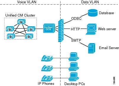
This figure shows an example of a network where voice and data components reside in separate VLANs and are separated by a firewall.
Figure 3. Unified CCX Accessing Data Stores

Unified CCX can communicate with these external sources through its subsystems, provided that Network Address Translation (NAT) is not used.

QoS and Call Admission Control

Quality of service (QoS) becomes an issue when more voice and application-related traffic is added to an already growing amount of data traffic on your network. Accordingly, Unified CCX and time-sensitive traffic such as voice need higher QoS guarantees than less time-sensitive traffic such as file transfers or emails (particularly if you are using a converged network).

QoS should be used to assign different qualities to data streams to preserve Unified CCX mission-critical and voice traffic. The following are some examples of available QoS mechanisms:
  • Packet classification and usage policies applied at the edge of the network, such as Policy Based Routing (PBR) and Committed Access Rate (CAR).

  • End-to-end queuing mechanisms, such as Low Latency Queuing (LLQ). Because voice is susceptible to increased latency and jitter on low-speed links, Link Fragmentation and Interleaving (LFI) can also be used to reduce delay and jitter by subdividing large datagrams and interleaving low-delay traffic with the resulting smaller packets.

  • Scheduling mechanisms such as Traffic Shaping to optimize bandwidth utilization on output links.

Unified CCX and Application-Related Traffic

The table lists TCP ports and DSCP markings for use in prioritizing Unified CCX and Unified CM mission-critical CTI traffic. The DSCP markings for call signaling traffic between Unified CCX and Cisco Unified Communication Manager and for voice traffic played from the Unified CCX server are set by default according to the traffic classification guidelines documented in Cisco Unified Communications System Design Guidance, available here:

http://www.cisco.com/go/ucsrnd.

Unified CCX does not mark any network traffic other than those mentioned here. As a result, traffic should be marked and prioritized at the edge according to the values in the table.

The performance criteria used in classifying this traffic includes:
  • No packet drops on the outbound or inbound interface of the WAN edge router

  • Voice (G.729) loss under 1percent

  • One-way voice delay under 150 ms

A detailed description of QoS is not within the scope of this design guide. For QoS design considerations, refer to the quality of service design guide available here:

http://www.cisco.com/go/designzone

Table 6. QoS Classifications for Unified CCX Interfaces

Unified CCX Component

Interface / Protocol

Port

DSCP Marking

Unified CCX Engine — CTI-QBE messaging destined to Unified CM from Unified CCX

CTI-QBE

TCP 2748

CS3

Unified CCX Administration and BIPPA Service — HTTP traffic destined for web administration and BIPPA interface on Unified CCX

HTTP / HTTPS

TCP 8443

AF21

Unified CCX Engine and Unified CCX Administration — SOAP AXL HTTPS messaging destined to Unified CM from Unified CCX

HTTPS / SOAP

TCP 8443

AF21

Unified CCX Engine — CTI messaging destined to Unified CCX from CAD clients

CTI

TCP 12028

CS3

Unified CCX Engine — RTP voice bearer traffic (bi-directional)

RTP

UDP 16384 - 32767

EF

CAC and RSVP

Unified CM supports Resource-Reservation Protocol (RSVP) between endpoints within a cluster. RSVP is a protocol used for Call Admission Control (CAC) and is used by the routers in the network to reserve bandwidth for calls. The bandwidth being controlled is only for the voice streams, call signalling traffic is not part of CAC.

Before RSVP, each Unified CM cluster maintained its own calculation of how many active calls were traversing between locations in order to calculate bandwidth usage. If more than one Unified CM cluster shared the same link, bandwidth would have to be carved out and dedicated for each cluster, and this led to inefficient use of available bandwidth. RSVP also enables customers to deploy complex network topology while location-based CAC is limited to a hub-and-spoke type of topology.

RSVP solves this problem by tracing the path between two RSVP Agents that reside on the same LAN as the IP Phones. A software MTP or transcoder resource that runs on Cisco IOS routers can be RSVP Agents. The RSVP Agents are controlled by Unified CM and are inserted into the media stream between the two IP phones when a call is made. The RSVP Agent of the originating IP Phone will traverse the network to the destination IP Phone's RSVP Agent, and reserve bandwidth. Since the network routers (and not Unified CM) are keeping track of bandwidth usage, multiple phone calls can traverse the same RSVP controlled link even if the calls are controlled by multiple Unified CMs.

For more information, see the RSVP chapter in Cisco Unified Communications Solution Reference Network Design (SRND).

Unified CCX selects a call center agent independent of the mechanism, using either RSVP or location-based CAC. Unified CCX routes a call to an available agent even though the agent phone might not be able to receive the call due to lack of bandwidth. Proper sizing of bandwidth between sites is very important.

For any call transfer, there are moments when two calls are active. If any of the active calls traverses between sites, then CAC is used. Even when the original call is placed on hold during a transfer, that call still takes up the same amount of bandwidth just like an active call.

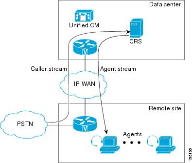
In the two examples that follow, the voice gateway and agents are at a remote site, while the Unified CCX server is at another site. A call from PSTN reaches the voice gateway at the remote site and connects to Unified CCX at the site. This takes one call bandwidth over the WAN link, which is represented by the caller stream. Once an agent is available and selected at the remote site, Unified CCX transfers the call to the agent.

Figure 4. Call From PSTN to Unified CCX Server to Agent

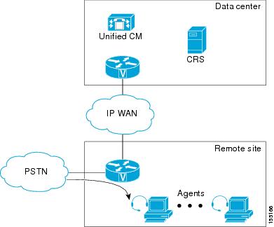
During the transfer, before the agent picks up the call, there is another call setup between Unified CCX and the agent phone. It takes up another call bandwidth over the WAN, and is represented by the agent stream in the previous example. Once the agent picks up the call, the voice traffic is between the voice gateway and the agent phone, which are both at the remote site. At that time, no bandwidth is reserved over the WAN, as illustrated in the following example. This example shows how call bandwidth is reserved in a contact center call that is eventually routed to an agent. Depending on where the voice gateway, the agents, and the Unified CCX server are located, proper WAN bandwidth should be provisioned.

Figure 5. After Agent Picks Up Call

Bandwidth Security and QoS Considerations for Unified Intelligence Center

The two bandwidth measurements in a Unified Intelligence Center installation include the following:

  • Bandwidth between the Unified Intelligence Center and data source

  • Bandwidth between the user and Unified Intelligence Center

The Unified CCX database is local to the server. In a normal operating mode, the bandwidth between Unified Intelligence Center and the data source can be ignored.


Note

Each report requires about 2.6 Mbps of bandwidth between the user and Unified Intelligence Center.


The configuration parameters that affect bandwidth include the following:

  • Number of rows in the report: 8000

  • Size of each row: 500 bytes

  • HTML size overhead for each row: 500 bytes

  • Time to transfer the rendered report from Unified Intelligence Center to the browser: 3 seconds

Reporting Scaling Considerations

Following are the reporting considerations:
  • A maximum of eight reporting users logged in concurrently on Cisco Unified Intelligence Center can view:
    • Four Live Data reports with 50 rows of 10 fields refreshing every 3 seconds.

    • Two historical reports with 2000 rows with 10 fields each refreshing every 30 minutes.

  • A maximum of 42 Finesse supervisors can view:
    • Three Live Data reports with 50 rows of 10 fields refreshing every 3 seconds.

  • A maximum of 358 Finesse agents can view:
    • Three real-time reports with 20 rows of 10 fields refreshing every 3 seconds.

Server Capacities and Limits

OVA Profile

The following table displays Open Virtualization Alliance (OVA) configuration settings to be used for Unified CCX:

Table 7. OVA Settings

Agent Capacity

vCPU

vRAM

vDisk

100 agents

2

8 GB

1 x 146GB

300 agents

2

8 GB

2 x 146GB

400 agents

4

16 GB

2 x 146GB

The following table provides a selected list of capacity limits when deploying Unified CCX.

Table 8. Capacity Limits

Deployment

Capacity

Maximum number of inbound agents

400

Maximum number of preview outbound agents

150

Maximum number of remote agents

100

Maximum number of supervisors

42

Maximum number of IVR ports

400

Maximum number of outbound IVR ports

150

Maximum number of progressive and predictive outbound agents

150

This table shows absolute limits. Reaching the limits for multiple criteria in a specific configuration might not be possible. Use the Cisco Unified Communications Sizing Tool to validate your configuration. This tool is available at:

http://tools.cisco.com/cucst

The Cisco Unified Communications Sizing Tool is available to Cisco partners only. For more details and to validate your configuration, contact your Cisco sales engineer or Cisco partner to access this tool.

For information on capacity and sizing of Cisco Workforce Optimization, refer to the Cisco Workforce Optimization System Configuration Guide.

The summary overview of system maximums for inbound and outbound voice listed in the table is for reference only.

Table 9. Reference Capacities for Inbound Systems

Inbound-Only System Maximum Capacities

Standalone Server

Two-Server Cluster

OVA profile

3

2

1

3

2

1

Agents

400

300

100

400

300

100

Supervisors

42

32

10

42

32

10

Finesse email

120

120

60

120

120

60

Email volume per hour

400

300

100

400

300

100

Web Chat concurrent sessions3

50

50

25

50

50

25

Web Chat concurrent sessions4

120

120

60

120

120

60

Web Chat volume per hour

2400

2400

1200

2400

2400

1200

Silent Monitoring

42

32

10

42

32

10

Recording and Playback using Finesse 5

N/A

N/A

N/A

N/A

N/A

N/A

Customer service queues

250

250

35

250

250

35

Skills

250

250

250

250

250

250

Historical reporting sessions

8

8

3

16

16

10

IVR ports6

400

300

100

400

300

100

ASR ports

100

100

50

100

100

50

TTS ports

160

160

40

160

160

40

VoiceXML ports

80

80

40

80

80

40

Busy Hour Call Completions (BHCC)

6000

5000

2000

6000

5000

2000

Number of skills with which an agent can associate

50

50

50

50

50

50

Number of CSQs with which an agent can associate (includes total combined email CSQs and voice CSQs)

25

25

25

25

25

25

Number of skills with which a CSQ can associate

50

50

50

50

50

50

Number of CSQs for which a call can queue

25

25

25

25

25

25

Number of agents per team

50

50

50

50

50

50

Maximum CSQs for Agent Email

100

100

10

100

100

10

3

Example; If your agent seat count is 100, you can have 25 chat sessions. If your agent seat count is 10, you can have 10 chat sessions.

4

Example; If your OVA profile is 1, the agent seat count is 100, you can have 60 chat sessions. If your agent seat count is 10, you can have 10 chat sessions.

5 The recording limit is based on the number of recording licenses deployed on Unified CCX. Appropriate capacity planning is required to perform recording and playback on MediaSense. For more information see, Solution Reference Network Design for Cisco MediaSense available here: http://www.cisco.com/en/US/products/ps11389/products_implementation_design_guides_list.html
6 The number of IVR ports is also limited by the maximum number supported for a given server platform. In case of virtualized deployment, the maximum number of IVR ports is limited by the maximum number supported for a given virtual machine template.
Table 10. Reference Capacities for Blended Inbound and Outbound Systems

Blended Inbound and Outbound System Maximum Capacities

Standalone Server

Two-Server Cluster

Agents

400

300

100

400

300

100

Supervisors

42

32

10

42

32

10

Silent Monitoring

42

32

10

42

32

10

Customer service queues

250

250

35

250

250

35

Skills

250

250

250

250

250

250

IVR ports

400

300

100

400

300

100

ASR ports

100

100

50

100

100

50

TTS ports

160

160

40

160

160

40

VoiceXML ports

80

80

40

80

80

40

Agent E-Mail concurrent agents

120

120

30

120

120

30

Web Chat concurrent sessions

7

120

120

60

120

120

60

Web Chat volume per hour

2400

2400

1200

2400

2400

1200

Blended or Preview Agents

150

150

75

150

150

75

Blended or Progressive/Predictive Agents

150

150

75

150

150

75

Preview Outbound BHCC

6000

5000

2000

6000

5000

2000

Progressive and Predictive Outbound BHCC

6000

5000

2000

6000

5000

2000

Outbound IVR BHCC

6000

5000

2000

6000

5000

2000

Total BHCC8

6000

5000

2000

6000

5000

2000

Number of skills with which an agent can associate

50

50

50

50

50

50

Number of CSQs with which an agent can associate

25

25

25

25

25

25

Number of skills with which a CSQ can associate

50

50

50

50

50

50

Number of CSQs for which a call can queue

25

25

25

25

25

25

Number of email CSQs

100

100

100

100

100

100

Outbound IVR ports

150

150

75

150

150

75

Maximum number of configured agents

2000

2000

2000

2000

2000

2000

7

Example; If your OVA profile is 1, the agent seat count is 100, you can have 60 chat sessions. If your agent seat count is 10, you can have 10 chat sessions.

8 For high-availability (HA) deployments, the BHCC listed in the table is for LAN deployments. For WAN deployments, BHCC is 5000, 750, and 750 for OVA profile 3 and 2, and 1, respectively. In addition, the BHCC contributed by the preview outbound dialer should not exceed 1000, 750 and 750 for OVA profile 3, 2, and 1, respectively. The BHCC contributed by Outbound IVR should not exceed 1000 and 750 for OVA profile 3 and 2 respectively. These reduced BHCCs apply only to HA over WAN deployments.

Note

All the capacities stated in this section are system maximums.


IPv6 Support

Unified CCX can be deployed as part of a dual stack IPv4 and IPv6 solution. Unified CCX servers and other optional servers (for example, ASR/TTS, WFM, QM etc) should be running in IPv4 segment. However, Unified CM, MediaSense servers, IP Phones and Gateways can be configured as either IPv4 or IPv6. If the calling device is in IPv6 and the receiving device is in IPv4, Unified CM dynamically inserts a media termination point (MTP) to convert the media between the two devices from IPv4 to IPv6 or vice versa. This would have an impact on Unified CM performance.

For more information on IPv6 deployment with Unified CM, refer to the document Deploying IPv6 in Unified Communications Networks with Cisco Unified Communications Manager available here:

http://www.cisco.com/go/ucsrnd

Unified CCX Software Compatibility

Unified CCX software is dependent upon integration with many other software components, especially Unified CM. Check that the Unified CCX release you are planning is supported with the Unified CM release for which this deployment is planned.

For the list of supported virtual servers for Unified CCX, see the Unified CCX Compatibility related information located at: http://www.cisco.com/c/en/us/support/customer-collaboration/unified-contact-center-express/products-device-support-tables-list.html.

Cisco Unified CCX Disk Space Usage

This section provides information about determining disk space usage and requirements when you install the Unified CCX. The historical reporting (HR) database (DB) size of the Unified CCX depends on the size of the hard disk on which it is stored. The following table provides an example of disk space usage for these DB types.

Table 11. Cisco Unified CCX Disk Space Usage

Sever Type

Server Disk Size

HR DB Size

Repository DB Size

Agent DB Size (rascal)

Configuration DB Size

100 Agent VM profile

1x146 GB

10.78 GB

40 MB

0.5 GB

0.5 GB

300 Agent VM profile

2x146 GB

12.45 GB

40 MB

0.5 GB

0.5 GB

400 Agent VM profile

2x146 GB

18.91 GB

40 MB

0.5 GB

0.5 GB

Deployment Guidelines for Agent Phones that Support G.722 or iLBC

Unified CCX can monitor and record only G.711 and G.729 agent calls. The newer version of some agent phones for Unified CM and Unified CM support G.722 and iLBC. If both the calling device (voice gateway or IP Phone) and agent phone support G.722 or iLBC, these codecs may be chosen as the preferred codec for the call, and monitoring and recording will fail. The following configurations can be used to prevent these codecs from being used in the call:

Unified CM

  • Disable advertising G.722 codec capability for the agent phone if the phone supports this codec.

  • In the Region used by the agent phone, set the audio codec as G.711 or G.729 only and do not set the Link Lossy Type as Lossy to prevent iLBC from being used.