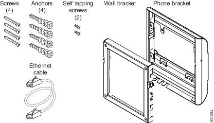
Wall Mounts

Wall Mount Kits

Each wall mount is unique to your phone model and cannot be used for another phone. If you are planning to attach your phone to a wall, purchase the wall mount kit specific to your phone. For additional information, refer to the phone model data sheet.

To check which phone model you have, press Applications and select Phone information. The Model number field shows your phone model.

Table 1. Wall Mount Kits

Cisco IP Phone

Cisco Wall Mount Kit

Cisco IP Phone 7811

Spare Wallmount Kit for Cisco IP Phone 7811

Cisco IP Phone 7821 and 7841

Spare Wallmount Kit for Cisco IP Phone 7800 Series

Cisco IP Phone 7861

Spare Wallmount Kit for Cisco IP Phone 7861

Non-Lockable Wall Mount Components for 7811

The following figure shows the components of the Cisco IP Phone 7811 Wall Mount Kit.

Figure 1. Wall Mount Kit Components for 7811


The package includes these items:
  • One phone bracket

  • One wall bracket

  • Four M4 x 25-mm Phillips-head screws with four anchors

  • Two M3 x 7-mm Self-tapping screws

  • One 200-mm Ethernet cable

This section describes how to install and remove the ADA nonlockable wall mount kit.

Figure 2. Back View of ADA Non-Lockable Wall Mount Kit Installed on Phone


Figure 3. Side View of ADA Non-Lockable Wall Mount Kit Installed on Phone


Install the Non-Lockable Wall Mount Kit for 7811

The wall mount kit can be mounted on most surfaces, including concrete, brick, and similar hard surfaces. To mount the kit on concrete, brick, or similar hard surfaces, you must provide the appropriate screws and anchors for your wall surface.

Before you begin

You need these tools to install the bracket:

  • #1 and #2 Phillips-head screwdrivers

  • Level

  • Pencil

You must also install an Ethernet jack for the phone in the desired location if an Ethernet jack does not currently exist. This jack must be wired appropriately for an Ethernet connection. You cannot use a regular phone jack.

Procedure


Step 1

Mount the wall bracket in the desired location. You can install the bracket over an Ethernet jack, or you can run the Ethernet network cable to a nearby jack.

Note 

If the jack is to be placed behind the phone, the Ethernet jack must be flush to the wall or recessed.

  1. Hold the bracket on the wall and place it so that the arrow on the back of the bracket points up.

  2. Use the level to ensure that the bracket is level and use a pencil to mark the screw holes.

  3. Using a #2 Phillips-head screwdriver, carefully center the anchor over the pencil mark and press the anchor into the wall.

  4. Screw the anchor clockwise into the wall until it is seated flush.

  5. Use the included screws and a #2 Phillips-head screwdriver to attach the bracket to the wall.

Figure 4. Bracket Installation
Step 2

Attach the phone bracket to the IP Phone.

  1. Detach the power cord and other attached cords from the base of the phone, except the handset cord (and headset cord, if there is a headset).

  2. Attach the phone bracket by inserting the tabs into the mounting tabs on the back of the phone. The phone ports should be accessible through the holes in the bracket.

  3. Reattach the cords and seat them in the clips that are incorporated into the phone body.

    Figure 5. Phone Bracket Attachment

    1

    Screw holes

Step 3

Attach the cables to the phone:

  1. Attach the Ethernet cable to the 10/100/1000 SW network port and wall jack.

  2. (Optional) If you are connecting a network device (such as a computer) to the phone, attach the cable to the 10/100/1000 Computer (PC access) port.

  3. (Optional) If you use an external power supply, plug the power cord into the phone. Dress the cord by clipping it into the clips that are incorporated into the phone body next to the PC port.

  4. (Optional) If the cables terminate inside the wall bracket, connect the cables to the jacks.

Figure 6. Cable Attachment

1

Phone Bracket

4

Handset Port

2

Network Port

5

AC Adapter Port

3

Wall Bracket

6

Optional Power Cable

Step 4

Attach the phone to the wall bracket by inserting the tabs on the top of the wall bracket into the slots on the phone bracket.

For cables that terminate outside of the brackets, use the cable-access openings in the bottom of the bracket to position the power cord and any other cable that does not terminate in the wall behind the bracket. The phone and wall bracket openings together form circular openings with room for one cable per opening.

Figure 7. Phone to Wall Bracket Attachment
Step 5

Press the phone firmly into the wall bracket and slide the phone down. The tabs in the bracket click into position.

Step 6

Proceed to Adjust the Handset Rest.


Remove the Phone from the Non-Lockable Wall Mount for 7811

The wall mounting plate contains two tabs to lock the plate into the phone bracket. The following figure shows the location and shape of the tabs.

Figure 8. Tab Location

To remove the phone and mounting plate from the wall bracket, you must disengage these tabs.

Before you begin

You require two screwdrivers or metal rods.

Procedure


Step 1

Push the screwdrivers into the left and right holes in the phone mounting plate approximately 1 in. (2.5 cm).

Step 2

Lift the screwdriver handles up to push down on the tabs.

Figure 9. Disengage Tabs
Step 3

Press firmly to disengage the tabs and move the phone up at the same time to release the phone from the wall bracket.


Non-Lockable Wall Mount Components

The following figure shows the components of the Cisco IP Phone 7800 Series Wall Mount Kit.

Figure 10. Wall Mount Kit Components


The package includes these items:

  • One phone bracket

  • One wall bracket

  • Four M8-18 x 1.25-inch Phillips-head screws with four anchors

  • Two M2.5 x 6-mm machine screws

  • One 6-inch Ethernet cable

This section describes how to install and remove the ADA nonlockable wall mount kit.

Figure 11. Back View of ADA Non-Lockable Wall Mount Kit Installed on Phone


Figure 12. Side View of ADA Non-Lockable Wall Mount Kit Installed on Phone


Install the Non-Lockable Wall Mount Kit

The wall mount kit can be mounted on most surfaces, including concrete, brick, and similar hard surfaces. To mount the kit on concrete, brick, or similar hard surfaces, you must provide the appropriate screws and anchors for your wall surface.

Before you begin

You need these tools to install the bracket:

  • #1 and #2 Phillips-head screwdrivers

  • Level

  • Pencil

You must also install an Ethernet jack for the phone in the desired location if an Ethernet jack does not currently exist. This jack must be wired appropriately for an Ethernet connection. You cannot use a regular phone jack.

Procedure


Step 1

Mount the wall bracket in the desired location. You can install the bracket over an Ethernet jack, or you can run the Ethernet network cable to a nearby jack.

Note 

If the jack is to be placed behind the phone, the Ethernet jack must be flush to the wall or recessed.

  1. Hold the bracket on the wall and place it so that the arrow on the back of the bracket points up.

  2. Use the level to ensure that the bracket is level and use a pencil to mark the screw holes.

  3. Using a #2 Phillips-head screwdriver, carefully center the anchor over the pencil mark and press the anchor into the wall.

  4. Screw the anchor clockwise into the wall until it is seated flush.

  5. Use the included screws and a #2 Phillips-head screwdriver to attach the bracket to the wall.

Figure 13. Bracket Installation
Step 2

Attach the phone bracket to the IP Phone.

  1. Detach the power cord and other attached cords from the base of the phone, except the handset cord (and headset cord, if there is a headset).

  2. Remove the label covers that conceal the screw holes.

    Note 
    Cisco IP Phone 7811 does not have label covers.
  3. Attach the phone bracket by inserting the tabs into the mounting tabs on the back of the phone. The phone ports should be accessible through the holes in the bracket.

  4. Reattach the cords and seat them in the clips that are incorporated into the phone body.

    Figure 14. Phone Bracket Attachment

    1

    Screw holes

    2

    Slots for mounting tabs

Step 3

Attach the cables to the phone:

  1. Attach the Ethernet cable to the 10/100/1000 SW network port and wall jack.

  2. (Optional) If you are connecting a network device (such as a computer) to the phone, attach the cable to the 10/100/1000 Computer (PC access) port.

  3. (Optional) If you use an external power supply, plug the power cord into the phone. Dress the cord by clipping it into the clips that are incorporated into the phone body next to the PC port.

  4. (Optional) If the cables terminate inside the wall bracket, connect the cables to the jacks.

Figure 15. Cable Attachment

1

Phone Bracket

4

Handset Port

2

Network Port

5

AC Adapter Port

3

Wall Bracket

6

Optional Power Cable

Step 4

Attach the phone to the wall bracket by inserting the tabs on the top of the wall bracket into the slots on the phone bracket.

For cables that terminate outside of the brackets, use the cable-access openings in the bottom of the bracket to position the power cord and any other cable that does not terminate in the wall behind the bracket. The phone and wall bracket openings together form circular openings with room for one cable per opening.

Figure 16. Phone to Wall Bracket Attachment
Step 5

Press the phone firmly into the wall bracket and slide the phone down. The tabs in the bracket click into position.

Step 6

Proceed to Adjust the Handset Rest.


Remove the Phone from the Non-Lockable Wall Mount

The phone mounting plate contains two tabs to lock the plate into the wall bracket. The following figure shows the location and shape of the tabs.

Figure 17. Tab Location

To remove the phone and mounting plate from the wall bracket, you must disengage these tabs.

Before you begin

You require two screwdrivers or metal rods.

Procedure


Step 1

Push the screwdrivers into the left and right holes in the phone mounting plate approximately 1 in. (2.5 cm).

Step 2

Lift the screwdriver handles up to push down on the tabs.

Figure 18. Disengage Tabs
Step 3

Press firmly to disengage the tabs and move the phone up at the same time to release the phone from the wall bracket.


Non-Lockable Wall Mount Components for 7861

The following figure shows the components of the Cisco IP Phone 7861 Wall Mount Kit.

Figure 19. Wall Mount Kit Components for 7861


The package includes these items:
  • One phone bracket

  • One wall bracket

  • Four M4 x 25-mm Phillips-head screws with four anchors

  • Two M3 x 7-mm Self-tapping screws

  • One 200-mm Ethernet cable

This section describes how to install and remove the ADA nonlockable wall mount kit.

Figure 20. Back View of ADA Non-Lockable Wall Mount Kit Installed on Phone


Figure 21. Side View of ADA Non-Lockable Wall Mount Kit Installed on Phone


Install the Non-Lockable Wall Mount Kit for 7861

The wall mount kit can be mounted on most surfaces, including concrete, brick, and similar hard surfaces. To mount the kit on concrete, brick, or similar hard surfaces, you must provide the appropriate screws and anchors for your wall surface.

Before you begin

You need these tools to install the bracket:

  • #1 and #2 Phillips-head screwdrivers

  • Level

  • Pencil

You must also install an Ethernet jack for the phone in the desired location if an Ethernet jack does not currently exist. This jack must be wired appropriately for an Ethernet connection. You cannot use a regular phone jack.

Procedure


Step 1

Mount the wall bracket in the desired location. You can install the bracket over an Ethernet jack, or you can run the Ethernet network cable to a nearby jack.

Note 

If the jack is to be placed behind the phone, the Ethernet jack must be flush to the wall or recessed.

  1. Hold the bracket on the wall and place it so that the arrow on the back of the bracket points up.

  2. Use the level to ensure that the bracket is level and use a pencil to mark the screw holes.

  3. Using a #2 Phillips-head screwdriver, carefully center the anchor over the pencil mark and press the anchor into the wall.

  4. Screw the anchor clockwise into the wall until it is seated flush.

  5. Use the included screws and a #2 Phillips-head screwdriver to attach the bracket to the wall.

Figure 22. Bracket Installation


Step 2

Attach the phone bracket to the IP Phone.

  1. Detach the power cord and other attached cords from the base of the phone, except the handset cord (and headset cord, if there is a headset).

  2. Attach the phone bracket by inserting the tabs into the mounting tabs on the back of the phone. The phone ports should be accessible through the holes in the bracket.

  3. Reattach the cords and seat them in the clips that are incorporated into the phone body.

    Figure 23. Phone Bracket Attachment


    1

    Screw holes

    2

    Slot for Mounting Tabs

Step 3

Attach the cables to the phone:

  1. Attach the Ethernet cable to the 10/100/1000 SW network port and wall jack.

  2. (Optional) If you are connecting a network device (such as a computer) to the phone, attach the cable to the 10/100/1000 Computer (PC access) port.

  3. (Optional) If you use an external power supply, plug the power cord into the phone. Dress the cord by clipping it into the clips that are incorporated into the phone body next to the PC port.

  4. (Optional) If the cables terminate inside the wall bracket, connect the cables to the jacks.

Figure 24. Cable Attachment


1

Phone Bracket

4

Handset Port

2

Network Port

5

AC Adapter Port

3

Wall Bracket

6

Optional Power Cable

Step 4

Attach the phone to the wall bracket by inserting the tabs on the top of the wall bracket into the slots on the phone bracket.

For cables that terminate outside of the brackets, use the cable-access openings in the bottom of the bracket to position the power cord and any other cable that does not terminate in the wall behind the bracket. The phone and wall bracket openings together form circular openings with room for one cable per opening.

Figure 25. Phone to Wall Bracket Attachment


Step 5

Press the phone firmly into the wall bracket and slide the phone down. The tabs in the bracket click into position.

Step 6

Proceed to Adjust the Handset Rest.


Remove the Phone from the Non-Lockable Wall Mount

The wall mounting plate contains two tabs to lock the plate into the phone bracket. The following figure shows the location and shape of the tabs.

Figure 26. Tab Location


To remove the phone and mounting plate from the wall bracket, you must disengage these tabs.

Before you begin

You require two screwdrivers or metal rods.

Procedure


Step 1

Push the screwdrivers into the left and right holes in the phone mounting plate approximately 1 in. (2.5 cm).

Step 2

Lift the screwdriver handles up to push down on the tabs.

Figure 27. Disengage Tabs


Step 3

Press firmly to disengage the tabs and move the phone up at the same time to release the phone from the wall bracket.


Adjust the Handset Rest

If your phone is wall-mounted or if the handset slips out of the cradle too easily, you may need to adjust the handset rest to ensure that the receiver does not slip out of the cradle.

Figure 28. Adjust the Handset Rest

Handset Rest Adjustment procedure

Procedure


Step 1

Remove the handset from the cradle and pull the plastic tab from the handset rest.

Step 2

Rotate the tab 180 degrees.

Step 3

Hold the tab between two fingers, with the corner notches facing you.

Step 4

Line up the tab with the slot in the cradle and press the tab evenly into the slot. An extension protrudes from the top of the rotated tab.

Step 5

Return the handset to the handset rest.