Web Development

Web API

Cisco Web API App

The Cisco Wireless Phone ships with the Cisco Web API app to support Web developers. The Cisco Web API app contains the JavaScript extensions necessary to support developer requirements, as detailed in this document. It allows developers to interface with external services and provide links to frequently used websites in addition to providing a way to configure the wireless phones to integrate with an XML application. The Web API provides:

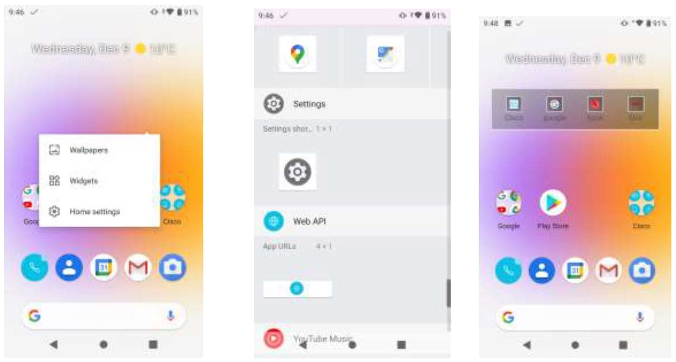
  • A widget to display a set of customer-defined URLs for applications and a special browser (WebView),

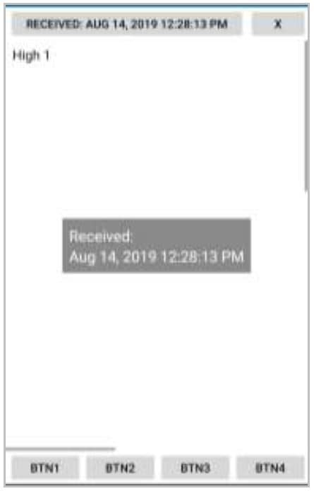
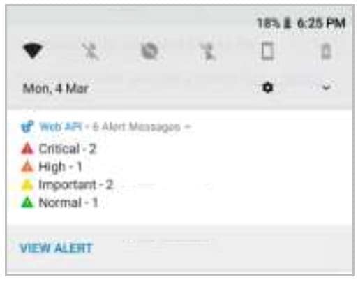
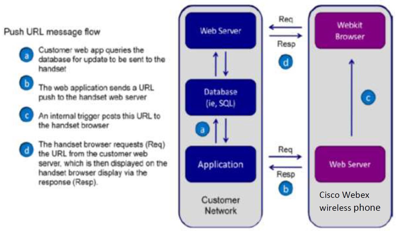
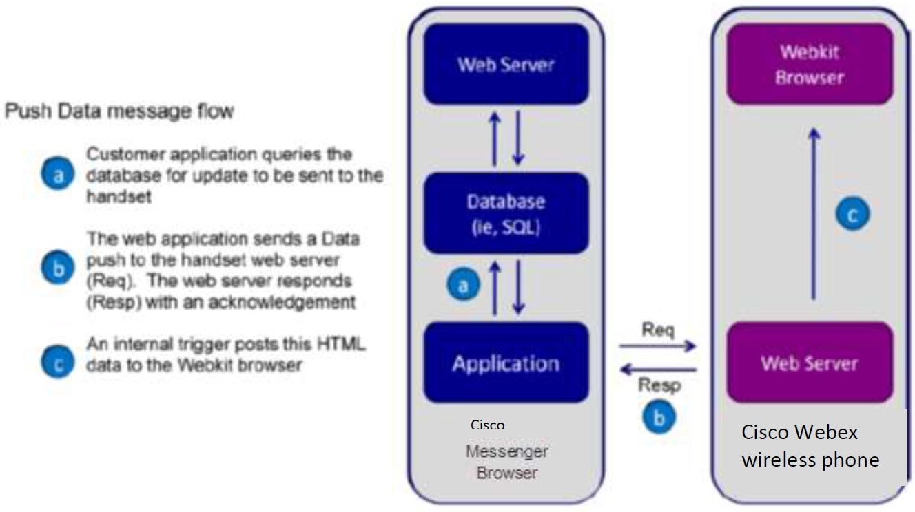
  • A custom notification management tool, AlertView, that gives applications the ability to push data or a URL to the phone and have it displayed in the AlertView notification window.

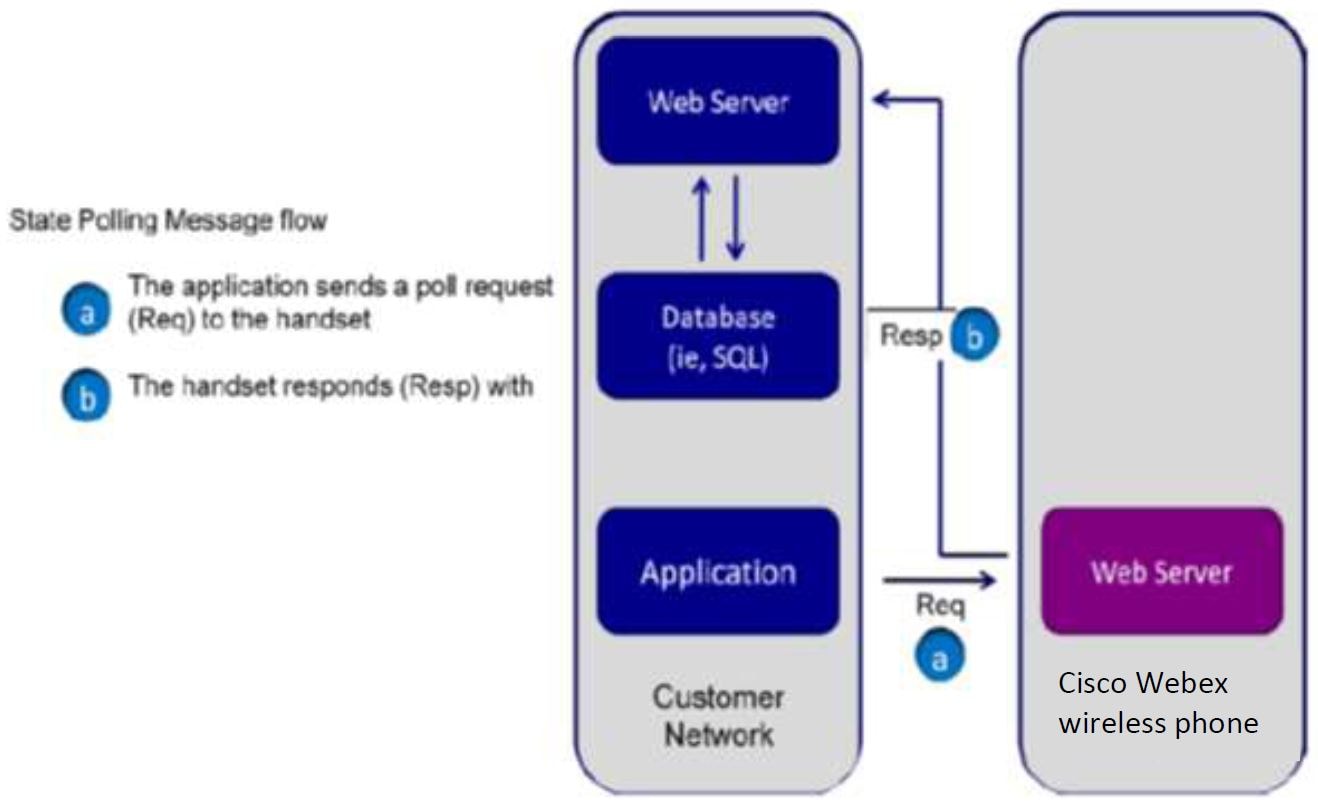
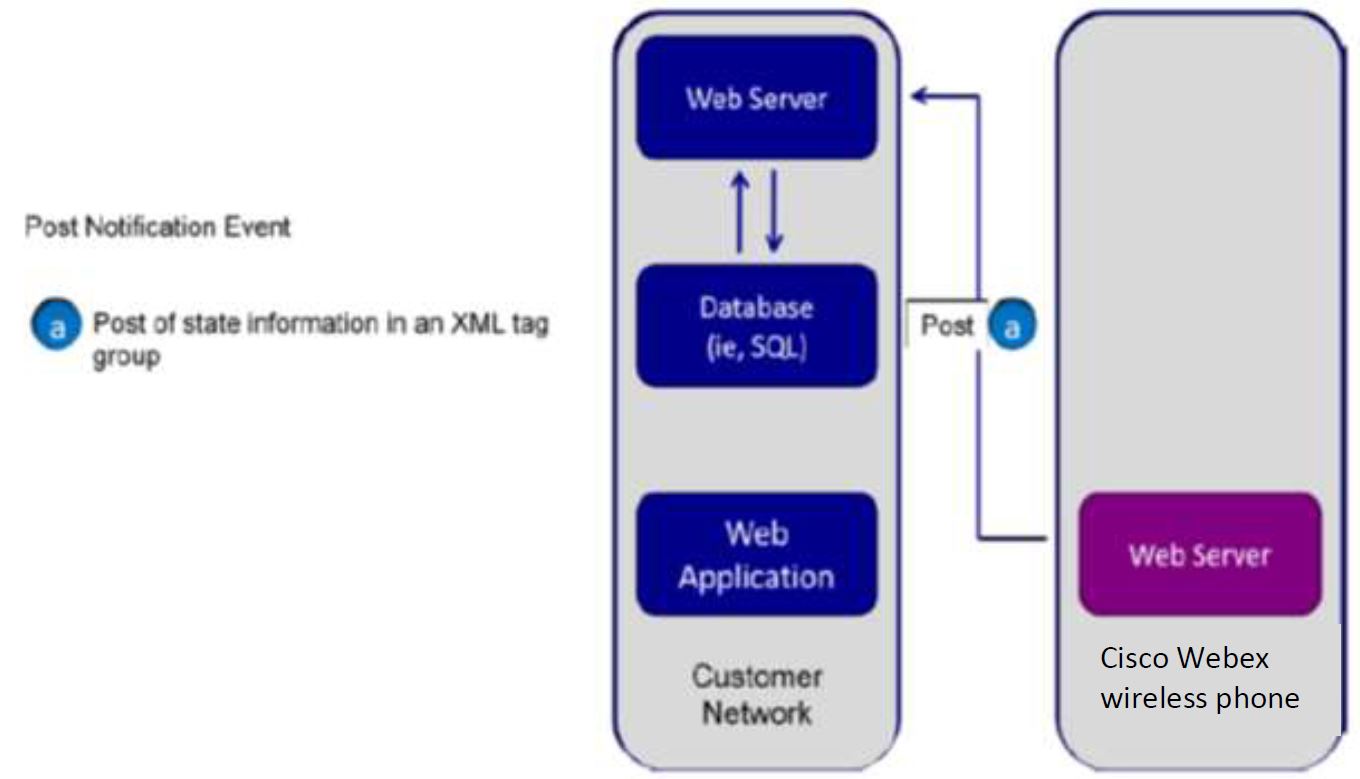
  • Provides the capability for applications to receive notifications of events or poll for status.

The Alertview notification window and the APP URLs widget ensure extended app availability for the Web API app.

By providing two separate activities for both pushed content and content the user has requested, content is separated, and the user does not lose the content that they asked for if pushed HTML content is sent to them:

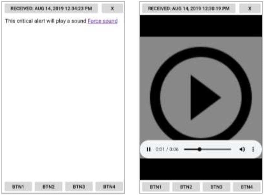
  • Pushed content is delivered to the user as a standard Android notification, which is displayed in the notification drawer. It is not assumed that all pushed content is more important than the current user activity. Therefore, only Critical priority pushed content will take over the user’s foreground activity and open the Alertview. Lower priority content is queued up and shown when the user selects the notification.

  • User-initiated links in the App URLs launch when the user opens the widget box containing the App URLs. Once tapped, the shortcuts open applications within a browser.

Interaction with other Android Applications

Because pushed content is sent to the Android notification manager the user can choose to handle it when they choose, except in the case of Critical priority content, which will notify the user audibly and will become the foreground activity. Thus, there is no adverse interaction with other running Android applications.

Interaction with Phone Calls

If the user is in a phone call they will not be interrupted by any pushed content except for critical priority content, which will notify them audibly and will take over the foreground activity. For information about limitations to the web API when a third-party VoIP application is used instead of the Cisco SIP application, see Appendix A

Other Browsers That May Be Installed on the Phone

Remember that the end user may have many other apps, including browsers, on their phone. These browsers will not contain the extensions that are present in the Cisco Web API app.

Web Development Overview

Web applications running on Cisco Wireless Phones can be as simple as a list of contacts or as complex as a nurse call system. Cisco Wireless Phones support App URLs, where users can interact with Web pages as they would on a computer.

Development of a web application for the Cisco Wireless Phone generally follows these steps:

  1. Planning. Defining the requirements of the application according to the facility’s needs.

  2. Familiarization of the capabilities of the Cisco Wireless Phone.

  3. Familiarization of the infrastructure requirements of the Cisco Wireless Phones – example: call control (telephony server), wireless LAN, etc. You will need to learn about the components of the entire system to implement your application. This knowledge is obtained through study of the Cisco Wireless Phone Deployment Guide and VIEW Program AP Guides.

  4. Application development and configuration requirements development. From your research on the requirements of the infrastructure, you will develop both the application itself and configure the parameters that the wireless phones need to use in order to integrate with the application. The settings will become central to testing your application and ultimately will be deployed along with the application in test and customer environments.

  5. The first phase of Application testing and debugging uses the Cisco Wireless Phone hardware, running your customized settings, and other components to mimic a telephony deployment: a simple wireless LAN environment and call server.

  6. The second phase of application testing uses Cisco Wireless Phones are deployed in a customer representative wireless LAN test environment. This test setup is detailed in this guide. During this test, applications can be tested for capacity as well as robustness for phones moving on and off the wireless LAN (due to power cycles and out of range movement).

  7. The third phase of application testing is done during deployment in a working environment.

  8. Launch.

Using XHTML

XHTML, or eXtensible HyperText Markup Language, is a family of XML markup languages that mirror or extend versions of the widely-used Hypertext Markup Language (HTML), the language in which web pages are written. XHTML is HTML 4.01 redesigned as XML.

You should ideally have experience working with HTML and XHTML programming or access to someone who has such experience to benefit from the information and discussion provided in this guide.

For more information, refer to the following online documents:


Note


You can use whichever development languages or servers you choose, including JavaScript, PHP, Python®, Django®, Tomcat™ or Apache™. Use whichever tools you are most comfortable using, or those that are most supported by your IT department.


Your Application and Cisco Wireless Phone

Cisco Wireless Phone is a powerful multi-touch phone that enables many types of applications, including native Android applications and Web-based applications.

Applications that are standard web applications or pages can be accessed using any web browser in the same manner as a user would on a wireless phone.

A web application that utilizes any of the features of the Cisco Wireless Phone Web API will use the Cisco App URLs instead of a common browser.

Alerts sent to the phone from a web application server will show up to the user in the Cisco Alertview in addition to creating an Android notification in the notification bar.

Cisco App URLs

The Cisco App URLs are web application shortcuts that open in a pared-down browser with enhanced Javascript capabilities designed specifically for onboard applications.

A user accesses the App URLs by using programmed shortcuts that open the application. The web application shortcut widget box supports up to 10 icons for App URLs.

Long press the home screen to open the Widgets option. Scroll down to display the Web API widget option. Long press and drag the widget box to a home screen.

Install the Apps URLs widget box. The App URLs shortcuts display together in a widget box.

The App URLs supports true Cisco Wireless Phone applications with the following features:

  • HTML 5 – without video support

  • CSS 3.0 – allowing only a single transition at a time.

  • SVG 1.1 (partial support)

  • JavaScript / The Web API app is used by developers to interface with external services and provide links to frequently used websites.

  • Web API allows you to configure the wireless phones to integrate with an XML application.DOM access

  • XMLHttpRequest

  • HTTP 1.1

  • AJAX

Cisco Alertview

The Cisco Alertview allows the user to see the top pushed Data or URL page (called an alert) in the queue that was sent to their Cisco Wireless Phone. It also sends notifications to the Android notification manager to alert the user of the number, and highest priority, of un-dismissed alerts.

It contains the following elements:

  • Title bar showing the HTML <Title> * A button to dismiss the alert from the queue * A progress bar showing the web page loading progress

  • Optionally shown softkeys (Btn1-4). See PolySoftKey.

Alertview example

Alertview that plays a sound. Force sound link opens a player

Use Cisco Alertview

When a new push (Data or URL) is received by the phone, the Cisco Alertview does the following:

  • Stores the push in the queue according to priority: Highest priority first and then ordered by received time - most recent first. See Using Push Requests.

Alertview notification example of multiple alerts

Once in the Alertview, a user can interact with your web application in the same manner as if they initiated the connection from a App URL shortcut. In fact, the User Agent of the App URLs and Alertview are identical.

App URLs Applications

The user can launch web applications in the Cisco App URLs widget box. When the user selects a web application by tapping its widget icon, the Cisco browser displays and the title bar shows a progress indicator as the page loads.

Handset behavior during App URLs functions

While the user is in a Cisco App URL page in the browser, if there is an event in the phone application that requires the user's attention (such as an incoming phone call), the incoming phone call activity displays automatically in the foreground and the Cisco App URL is placed on the recent activity list, just like on a consumer wireless phone. The user can return to the Cisco App URL by selecting it off the recent activity list, or by pressing the Back key.


Note


App URL display and other activities are not always interrupted. Not all events require the user’s attention to the display, for example, Push-to-talk audio traffic plays out the rear speaker without interrupting the current activity’s display.


Handset Configuration

The wireless phones are configured to reach and interact with the web application through their Web API configuration, which must be set accordingly. Configuration will include:

  • The wireless phones must be configured to find the web application. At a minimum you will need to configure a URL location for the application itself and a label to display on the web app shortcut widget, which the user uses to initiate the application.

  • The wireless phone must be configured to send required event notifications to the application server, minimally to notify the application of its IP address when it comes onto the wireless network.

  • When applicable, the wireless phone must be configured to receive incoming pushes for the application to send alerts to the wireless phone.

  • Other parameters can be required if your application requires telephony features such as personal alarms or emergency dial. The Cisco Wireless Phone Administration Guide will provide you will full details about Cisco application deployment.

Configuration information

You will need to set up your test phones with the parameters your web application requires to test your Application. While you can use a full-blown Enterprise Mobility Management (EMM) server to configure the Web API settings in your test phones, we recommend that you simply use the manual method for a small number of phones.

Overview of the Cisco Wireless Phone Web API

The Cisco Wireless Phone Web API includes a powerful set of web-based application tools, that are designed to integrate easily into almost any enterprise-grade application environment. There are several key functional API tools which will be fundamental elements of your application interface. The most valuable and necessary mechanisms are outlined in the sections that follow.

At a high level, the Cisco Wireless Phone Web API uses the standard HTTP post mechanism to both send status from the phone and to allow external servers to send alert messages to the phone. The messages use XML as their syntax. The Web API also includes JavaScript callable DOM extensions inside the Cisco App URLs and Cisco Alertview. These extensions allow a web application to access capabilities not typically available within a web browser sandbox. These capabilities include playing audio files and initiating telephone calls.

The network flow diagrams provided in the following sections, represent only one example of how an applications delivery platform might be architected. For example, in some instances, the web server and application server could be the same. Several of the functional blocks are indicated separately for clarity.


Note


The API is case sensitive, ensure you follow case guidelines exactly as any change may adversely affect the results.


See Telephony Integration for an in-depth explanation of each Web API function.

Push URL

The Push URL mechanism is typically used to create an application-generated message, alarm or alert on the phone, to be displayed through the Cisco Alertview browser. This action, results in the Alertview receiving a URL address downloaded from the application web server.

The Push URL function supports the following two types of content URLs:

  • XHTML content URL: The content will be displayed on Alertview. If it is not already open, it opens and displays the pushed message on Alertview.

  • URI actions content URL: The URI actions specified in the file are executed on the wireless phone.

Figure 1. The REST API Push URL Message Flow

Push Data

Instead of pushing a URL using the Push URL mechanism, you can push a small amount of HTML data directly from the application to the Cisco Alertview on the target wireless phone(s).

This feature does not allow for URI actions in the message, but URI actions can be defined as anchors within the Push Data mechanism. This tool is useful for broadcast messages especially to a large group of users, as the impact of a large number of browsers, i.e. Alertviews, requesting a URL from a web server simultaneously is avoided (as a Push URL would require).

The general message flow is summarized as follows:

Figure 2. The REST API Push Data Message Flow

Internal URIs

Internal URIs are execution events that can be used for executing predefined actions in a specific scenario. It is similar to the manual execution of key presses. The wireless phone executes Internal URIs in the order they are received. The URIs must be defined in sequence and separated by a “;” (semicolon) character or newline character and the file should be served with content type application/x-com-Cisco-webx. This file can be sent to wireless phone using a URL push message.

Phone State Polling

Phone state polling enables you to fetch the following wireless phone configuration and call state information:

  • Call Processing State

  • Device Information

  • Network Configuration

When the device receives any of these polling requests, it prepares the information in an XML format, and sends it to the configured polling URL or to the device that requested the Poll, depending on the state of the State Polling Response Method.

Figure 3. The REST API Polling Message Flow

Event Notification

The wireless phone-initiated event notification is based on a state change in the wireless phone or a network connection event. This mechanism is used to integrate endpoint events into host application intelligence. When an Event Notification is triggered it prepares the information in XML format and sends it to the configured event notification URL.

Figure 4. The REST API Post notification event

Telephony Integration

To fully utilize the power of the Cisco Wireless Phone Web API on a Cisco Wireless Phone, you will need to understand what the telephony functions are and how to write a program that utilizes them. Additionally, you will need to understand how to configure the wireless phone settings to work with your application. This chapter covers the telephony functions that you can use and how the Push requests, Event notifications and Phone state polling functions operate. Configuration to enable these features is covered in the next chapter.


Note


Telephony integration is designed for the Cisco Wireless Phone application. All integration features detailed here are only for use with the Cisco Wireless Phone app in a Wi-Fi environment.


Note


Examples have wrapped lines. Be aware that the lines of code shown in this document are formatted to fit the page and may appear wrapped. If you cut and paste these lines, they may inadvertently contain line breaks. Check for valid code before executing.


Telephone Integration URIs

Internal Uniform Resource Identifiers (URIs) provide the interface to execute predefined actions on the phone. These actions give you as a developer action to some internal functions that normally would take manual user action to perform.

There are two (2) ways to execute an internal URI action, as follows:

  • The internal URIs can be sent as Data Push where content type must be: application/x-com-Cisco-webx

  • If an XHTML file will include internal URI, they must be defined in (and executed from) anchor tags, in the href attribute (for example, <a href=tel:1234>Menu</a>). When the user selects the anchor, the action is processed and executed (in this case, dial phone number 1234).


Note


Internal URI actions contained in a file with content type “application/x-com-Ciscowebx” can be executed only through a URL push.


Use the following format when configuring the internal URIs:

ActionType:Action

where:

  • ActionType is the type of action to execute (Tel, or Play)

  • Action is the name/content of the action to be executed.

The supported internal URIs are described in the table shown next.

Table 1. Supported Internal URIs

Action Type

Action

Tel2, 3

The Tel URI initiates a new call to the specified number. Any digit map rules are followed.

Tel:[numbertodial]

Play4

Download and play the audio file.

The <audiofile_path> is the relative path on the application server, relative to the Server Root URL.

Play:<audiofile_path>

The LineIndex value is case insensitive.

If there are already 4 calls in progress the tel: URI request is ignored.

An error is logged in a log file if the file is too large to play.

Keep in mind that the following important notes regarding internal URIs:


Note


Registration 2 is commonly used for in-house call systems that use registration 2 to call an extension for alerts and other messages. For example, use tel:Reg2:2002 to place a call on registration 2 to extension 2002.


Note


A two-second pause is indicated by the “,” (comma). A one-second pause is indicated by a p character. The dual-tone multi-frequency (DTMF) is sent after the placed call is connected when specified after postd= as shown in the example below.


Example: Place a call to *50, and then wait two seconds before entering 44:

<html>
<head>
</head>
<body>
<a href="tel:*50;postd=,44">Push to Dial</a>
</body>
</html>

Note


Ensure you specify the file format extension of any audio files, e.g. alertsoundA.wav. The preferred supported file format is WAVE, G711 mu law or A law, 8KHz sampling rate, 8 bits per sample, monaural (aka mono). Audio software such as Audacity® can be used to create sound files of the correct format.


Use Push Requests

A push request is defined as an XML formatted request that you send to a phone to tell it to process the XML content. The phone may render the data, fetch a URL, or perform an action, depending on the content of the XML.


Note


See Push Settings for a list of parameters you can use to enable push requests in the wireless phone.

Cisco Wireless Phone will convert PUSH request URLs to lower-case, so in effect the device will attempt to retrieve web pages and files using lower case.


Note


If a phone is in call and is sent a tel: push request that is with priority: high, normal or important), the phone accepts the push but does nothing. Only If the priority is critical will the call be placed immediately.


HTTP <URL> Push

The HTTP URL push enables an application to push a URL to a phone for the App URLs to open, such as an HTML Web page for display. The value sent within the push request is ‘relative’ because it is relative to the URL configured by the Server root URL parameter (the pushed URL is appended to this ‘root’ URL, and this is what the App URLs will attempt to open). This feature is asynchronous, because once the push request is received by the wireless phone, it returns a 2xx or 4xx response immediately without waiting. There will be no success/failure feedback for the push handling itself. The pushing application will not know if the App URLs was able to open the pushed URL or not. The server that sends the requested page will know because it will see the page requests from the App URLs.

Use the following format when configuring the HTTP URL Push:

<URL priority=’X’ volume=’Y’ >URI path</URL>

The URL push requests support the attributes listed in the table shown next.

Table 2. URL Push Request Attributes

Attribute

Permitted Values

priority1

Critical, Important, High, Normal

Sets the priority of the push, which determines how and when the URL is requested. For more information, refer to the next table. Priority must be all lower case: priority. The value must have single quotes (‘).

URI path2

String

Any relative URI (or relative URI path) on the configured application server.

volume

0 to 100

Sets an override volume for any custom alert tone embedded in the page. (See PolyUri for more information on custom embedded alert tones.) Volume must be all lower case: volume. The value must have single quotes (‘).

2 Multiple URIs in a single push request are not supported.

1 If attribute is absent, Normal is used.


Note


The order of the priority and volume setting must adhere to the order shown in the example with priority first, followed by volume. Also note that the volume value must have single quotes and the priority value must have single quotes.


Note


The <URL> tag must be defined under a <SpectralinkIPPhone> root tag. For example:

<SpectralinkIPPhone>
<URL priority=’Normal’ volume=’100’ >/examples/media.xhtml</URL>
</SpectralinkIPPhone>

The following table describes the results of using a specific priority when the phone is in different states.

Table 3. How Priority Affects URL and HTML Push Requests

Phone State

Priority

Description

Locked/Unlocked with screen off

Critical

The phone will display push request immediately: Notification sound will play, Notification in Notification Area will show, Screen wakes up, Cisco Alertview activity starts in the foreground displaying the push.

High

The phone plays the notification tone and Notification in the Notification Area will show, however the screen does not wakeup.

Important

The phone plays the notification tone and Notification in the Notification Area will show, however the screen does not wakeup.

Normal

The phone plays the notification tone and Notification in the Notification Area will show, however the screen does not wakeup.

Unlocked with screen on, not in phone call

Critical

The phone will display push request immediately: Notification sound will play, Notification in Notification Area will show, Cisco Alertview activity comes to the foreground displaying the Push

High

The phone plays the notification tone and Notification in the Notification Area will show.

Important

The phone plays the notification tone and Notification in the Notification Area will show.

Normal

The phone plays the notification tone and Notification in the Notification Area will show.

Unlocked in phone call

Critical

The phone will display push request immediately: Notification sound will play mixed in with the phone audio, Notification in Notification Area will show, Cisco Alertview activity starts in the foreground displaying the push.

High

The phone does not play the notification tone and Notification in the Notification Area will show.

Important

The phone does not play the notification tone and Notification in the Notification Area will show.

Normal

The phone does not play the notification tone and Notification in the Notification Area will show.


Note


See Push Settings for the settings that are required for the wireless phone to receive a push request. If these are not configured any push message sent to the wireless phone will be discarded.


Keep in mind the following important notes regarding HTTP URL push:

  • The URL that the phone ultimately ends up fetching is a concatenation of the Server root URL and the URL sent in the Push URL message.


Note


Server root URL can be defined to be Null. See Push Settings for complete information.

  • Push requests are displayed as ‘first-in-first-out’ except for noted in the table above.

  • All HTTP requests are challenged through HTTP Digest Authentication.

  • If the phone cannot fetch the content from the pushed URI, the request is ignored.


For example, if Server root URL is configured in a phone to be http://1.2.3.4/apps then to push the display of a XHTML page media.xhtml, you would send the following XHTML.

<SpectralinkIPPhone>
<URL priority='Normal'>/examples/media.xhtml</URL>
</SpectralinkIPPhone>

where media.xhtml is hosted by a web server at http://1.2.3.4/apps/examples/media.xhtml.

Data Push of Complex URLs

If a URL is pushed to the phone that contains an ampersand (&), the wireless phone truncates the URL at the ampersand. Two workaround options are:

  • Do a data push which instantly re-directs to the desired URL

    <SpectralinkIPPhone>
    <Data priority='%s'><html><head><title>redirecting...
    </title></head>
    <body onload="window.location='http://12.34.56.78/
    NOTIFY.HTML?DEVID=2105010250&EVENTID=%7BA71C2393-8276-4484-A0E5-
    5666DA06A5C1%7D'">redirecting...
    </body>
    </Data>
    </SpectralinkIPPhone>
  • Add a hidden form with which to send the data: Applies to most cases (where you are not accessing the GET variables directly w/ JavaScript).

    <form name="form" action="someServerPage" method="POST">
    <input type="hidden" name="DEVID" value="2105010250" />
    <input type="hidden" name="EVENTID" value="%7BA71C2393-8276-4484-A0E5-
    5666DA06A5C1%7D" />
    </form>
    <a href="#" onclick="document.form.submit()">notify device</a>

Some additional logic would be required on the server to send the correct information (accessible via the POST header of the HTTP request) back with NOTIFY.HTML but it would vary with language / framework / use case.

As a bonus, POSTed requests are considered more secure than GET style requests which include variables visible in the URL.

HTML <Data> Push

The data push enables you to send XHTML page content directly to a phone, without the overhead of the phone having to request the XHTML.

Use the following format when sending the HTML Data Push:

<Data priority='X' volume=Y >Y</Data>

The HTML push requests support the attributes listed in the following table.

Table 4. HTML Push Requests

Attribute

Permitted Values

priority1

Critical, Important, High, Normal

Sets the priority of the push (X in the above example), which determines how and when the URL is requested. Priority must be all lower case: priority. The value must have single quotes (‘).

text

Text in HTML format

Any text (Y in the above example).

volume

0 to 100

Sets an override volume for any custom alert tone embedded in the page. (See PolyUri for more information on custom embedded alert tones.) Volume must be all lower case: volume. The value must have single quotes (‘).

1 If attribute is absent, Normal is used.


Note


The order of the priority and volume setting must adhere to the order shown in the example with priority first, followed by volume. Also note that the volume value must have quotes and the priority value must have single quotes.


Note


Tags must be defined under a <SpectralinkIPPhone> root tag:

  • Data must have a capital D: Data

  • Volume must be all lower case: volume

  • Priority must be all lower case: priority


Note


Push URL and Push Data requests follow the same priority described in HTTP <URL> Push Table: How Priority Affects URL and HTML Push Requests.


Note


When performing a data push, any referenced CSS files must be an absolute path. Therefore, with a data push, the serverRoot URL is not included in the CSS file path.


Example: To push the display of an important message:

<SpectralinkIPPhone>
<Data priority='Important' volume=’100’> <h1> Fire Drill at 2pm </h1>
Please exit and congregate at your appropriate location outside </Data>
</SpectralinkIPPhone>

Note


See Push Settings for the settings that are required for the wireless phone to receive a push request. If these are not configured you can push a message to the wireless phone but it will be discarded.


Use Event Notifications

Event Notifications allow application programs insight into what wireless phones are doing, their status and their network information. Using a combination of them will allow an application to detect the power up of phones and the state of the phones.

For example, using a combination of events and phone state polls can allow an application to detect that a phone has registered with the call server (Line Registration Event) and then get the phone’s extension number, model # and firmware version (Device Info phone state poll).

The phone can be configured to send information to a specific URI if one of the following Event Notifications occurs:

  • Personal Alarm Event

  • Incoming Call Event

  • Outgoing Call Event

  • Offhook Event

  • Onhook Event

  • Call State Change Event

  • Line Registration Event

  • Line Unregistration Event

These events are XML data posted to a Web server by the phone.


Note


If you have configured a second registration for use by your application, you may use the <LineNumber> parameter to return information to differentiate the line.


Note


The header tag in the XML that identifies a Cisco Wireless Phone event notification <SpectralinkIPPhone> is not present in the event notification responses.


Viewing a Personal Alarm Event

The Alarm Event can be used by a security application to record, track or otherwise manage an alarm event that has been triggered by the SAFE application. Alarm events occur when Running, Tilt, and No movement alarms are triggered and when Panic button (duress) calls are made.

Use the following format when viewing the alarm event:

<SafeEvent>
<PhoneIP> </PhoneIP>
<CellularIP> </CellularIP>
<MACAddress> </MACAddress>
<BSSID> </BSSID>
<StillAlarm> </StillAlarm>
<TiltAlarm> </TiltAlarm>
<RunningAlarm> </RunningAlarm>
<DuressAlarm> </DuressAlarm>
<LineNumber> </LineNumber>
<TimeStamp> </TimeStamp>
<Latitude> </Latitude>
<Longitude> </Longitude>
</SafeEvent>
Table 5. Alarm Notification Event Attributes

Attribute

Permitted Values

Phone IP

IP address

IP address of the phone. For example

172.24.128.160

Cellular IP (96-Series only)

IP address

Cellular IP address of the LTE phone if a working SIM card is installed.

Note


In a Wi-Fi environment, the phone will not “know” its cellular IP address until it needs to use LTE. Therefore, disable Wi-Fi to allow the phone to find the LTE network. The Cellular IP address will become available at that point and continue to be used when needed.

MACAddress

MAC Address

MAC address of the phone. For example:

00907a0e0f37

BSSID

MAC Address

The MAC address of the AP the phone is currently using.

Still Alarm

0 = no alarm, 1 = alarm

The current state of this alarm detector.

Tilt Alarm

0 = no alarm, 1 = alarm

The current state of this alarm detector.

Running Alarm

0 = no alarm, 1 = alarm

The current state of this alarm detector.

Duress Alarm

0 = no alarm, 1 = alarm

The current state of this alarm detector.

LineNumber

0 or 1

Returns 1 if an emergency call number is configured and 0 if no emergency call number is configured.

TimeStamp

time

The date and time that the event occurred on the phone. For example:

2013-05-11T13:19:53-08:00

Latitude

Current coordinates obtained from GPS

Na for Wi-Fi (no GPS)

LTE only (96-Series only)

example <Latitude>40.02565302689416</Latitude>

Longitude

Current coordinates obtained from GPS

Na for Wi-Fi (no GPS)

LTE only (96-Series only)

example: <Longitude>-105.22406386251863</Longitude>

Viewing an Incoming Call Event

The Incoming Call Event can be used by an application to send metadata about the call to the phone in real time, or to allow the application to detect that the user of the phone is busy.

Use the following XML format when viewing the incoming call event:

<IncomingCallEvent>
<PhoneIP> </PhoneIP>
<CellularIP> </CellularIP>
<MACAddress> </MACAddress>
<CallingPartyName> </CallingPartyName>
<CallingPartyNumber> </CallingPartyNumber>
<CalledPartyName> </CalledPartyName>
<CalledPartyNumber> </CalledPartyNumber>
<LineNumber> </LineNumber>
<TimeStamp> </TimeStamp>
</IncomingCallEvent>

The incoming call event contains the attributes listed in the following table.

Table 6. Incoming Call Event Attributes

Attribute

Permitted Values

Phone IP

IP address

IP address of the phone. For example

172.24.128.160

Cellular IP (96-Series only)

IP address

Cellular IP address of the LTE phone if a working SIM card is installed.

MACAddress

MAC Address

MAC address of the phone. For example:

00907a0e0f37

CallingPartyName

name

The name displayed in phone's ‘From’ label in screen. If the line is registered and the call is initiated from that line, then the registered line display name of the calling party is shown. If the line is not registered and the call is initiated from that line, then IP address of the calling party is shown. For example:

sip:172.24.128.160

CallingPartyNumber

number

The number displayed on the phone. If the line is registered and the call is initiated from that line, the registered line number of the calling party is shown. If the line is not registered and the call is initiated using IP address from that line, the IP address of the calling party is shown.

CalledPartyName

name

The name displayed in phone's To label on screen. If the call is received by a registered line, the registered line display name of the called party is shown. If the call is received on a non registered line, the IP address of the called party is shown.

CalledPartyNumber

number

The number displayed on the phone. If the call is received by a registered line, the registered line number of the called party is shown. If the call is received on a nonregistered line, the IP address of the called party is shown.

LineNumber

1 or 2

Returns 1 for SIP registration 1 and 2 for SIP registration 2.

TimeStamp

time

The date and time that the event occurred on the phone. For example:

2013-05-11T13:19:53-08:00

When the event notification URI is set and the incoming call event is enabled to gather information, the following example shows the transmitted data for a call between one registered and one unregistered line:

<IncomingCallEvent>
<PhoneIP>172.24.132.135</PhoneIP>
<MACAddress>0004f214b89e</MACAddress>
<CallingPartyName>20701</CallingPartyName>
<CallingPartyNumber>20701@172.18.186.94</CallingPartyNumber>
<CalledPartyName>20300</CalledPartyName>
<CalledPartyNumber>20300</CalledPartyNumber>
<TimeStamp>2008-07-11T13:19:53-08:00</TimeStamp>
</IncomingCallEvent>

Viewing an Outgoing Call Event

The Outgoing Call Event can be used by an application to detect that the user of the phone is busy in a call.

Use the following XML format when viewing the outgoing call event:

<OutgoingCallEvent>
<PhoneIP> </PhoneIP>
<CellularIP> </CellularIP>
<MACAddress> </MACAddress>
<CallingPartyName> </CallingPartyName>
<CallingPartyNumber> </CallingPartyNumber>
<CalledPartyName> </CalledPartyName>
<CalledPartyNumber> </CalledPartyNumber>
<LineNumber> </LineNumber>
<TimeStamp> </TimeStamp>
</OutgoingCallEvent>

The outgoing call event contains the attributes listed in the following table.

Table 7. Outgoing Call Event Attributes

Attribute

Permitted Values

Phone IP

IP address

IP address of the phone. For example

172.24.128.160

Cellular IP (96-Series only)

IP address

Cellular IP address of the LTE phone if a working SIM card is installed.

MACAddress

MAC Address

MAC address of the phone. For example:

00907a0e0f37

CallingPartyName

name

The name displayed in phone's From label in screen. If the line is registered and the call is initiated from that line, then the registered line display name of the calling party is shown. If the line is not registered and the call is initiated from that line, then IP address of the calling party is shown. For example:

sip:172.24.128.160

CallingPartyNumber

number

The number displayed on the phone. If the line is registered and the call is initiated from that line, the registered line number of the calling party is shown. If the line is not registered and the call is initiated using IP address from that line, the IP address of the calling party is shown.

CalledPartyName

name

The name displayed in phone's To label in screen. If the call is received by a registered line, the registered line display name of the called party is shown. If the call is received on a nonregistered line, the IP address of the called party is shown.

CalledPartyNumber

number

The number displayed on the phone. If the call is received by a registered line, the registered line number of the called party is shown. If the call is received on a nonregistered line, the IP address of the called party is shown.

LineNumber

1 or 2

Returns 1 for SIP registration 1 and 2 for SIP registration 2.

TimeStamp

time

The date and time that the event occurred on the phone. For example:

2013-05-11T13:19:53-08:00

When the event notification URI is set and the incoming call event is enabled to gather information, the following example shows the transmitted data for a call between one registered and one unregistered line:

<IncomingCallEvent>
<PhoneIP>172.24.132.135</PhoneIP>
<MACAddress>0004f214b89e</MACAddress>
<CallingPartyName>20701</CallingPartyName>
<CallingPartyNumber>20701@172.18.186.94</CallingPartyNumber>
<CalledPartyName>20300</CalledPartyName>
<CalledPartyNumber>20300</CalledPartyNumber>
<TimeStamp>2008-07-11T13:19:53-08:00</TimeStamp>
</IncomingCallEvent>

Viewing a Call State Change Event

The Call State Change event notifies the application of the different call states that can exist on the phone.

Use the following format when viewing the call state change event:

<CallStateChangeEvent CallReference=" " CallState=" ">
<PhoneIP> </PhoneIP>
<CellularIP> </CellularIP>
<MACAddress> </MACAddress>
<LineNumber> </LineNumber>
<TimeStamp> </TimeStamp>
<CallLineInfo>
<LineKeyNum> </LineKeyNum>
<LineDirNum> </LineDirNum>
<LineState> </LineState>
<CallInfo>
<CallState> </CallState>
<CallType> </CallType>
<UIAppearanceIndex> </UIAppearanceIndex>
<CalledPartyName> </CalledPartyName>
<CalledPartyDirNum> </CalledPartyDirNum>
<CallingPartyName> </CallingPartyName>
<CallingPartyDirNum> </CallingPartyDirNum>
<CallReference> </CallReference>
<CallDuration> </CallDuration>
</CallInfo>
</CallLineInfo>
</CallStateChangeEvent>

The call state change event contains the attributes listed in the following table.

Table 8. Call State Change Event Attributes

Attribute

Permitted Values

Phone IP

IP address

IP address of the phone. For example

172.24.128.160

Cellular IP (96-Series only)

IP address

Cellular IP address of the LTE phone if a working SIM card is installed.

MACAddress

MAC Address

MAC address of the phone. For example:

00907a0e0f37

LineNumber

1 or 2

Returns 1 for SIP registration 1 and 2 for SIP registration 2.

TimeStamp

time

The date and time that the event occurred on the phone. For example:

2008-07-11T13:19:53-08:00

CallReference

number

A unique identifier for a call.

LineKeyNum

1, 2 or 4

Used in polling to determine which registration is responding or if IP dialing has been used. Returns 1 for SIP registration 1 and 2 for SIP registration 2. Returns 4 for IP dialing.

LineDirNum

phone number

Phone number associated with line. For example:

1234

LineState

OK,

[any value that is not “OK” indicates a registration error that will be specific to the PBX.]

The line state.

CallState

Outgoing call states: Setup, RingBack

Incoming call states: Offering

Outgoing/Incoming call states:

Connected, Disconnected

CallConference, CallHold, CallHeld,

CallConfHold, CallConfHeld

The call state.

CallType

Incoming, Outgoing

The call type.

UIAppearanceIndex

string

The call appearance index. This number simply shows the order of the call appearance on the display.

CalledPartyName

name

If the line is registered, the value is the registered line display name.

If the line is not registered, the value is the IP address of the called party.

CalledPartyDirNum

number

If the line is registered, the value is the registered line number.

If the line is not registered, the value is the IP address of the called party.

CallingPartyName

name

If the line is registered, the value is the registered line display name.

If the line is not registered, the value is the IP address of the calling party.

CallingPartyDirNum

number

If the line is registered, the value is the registered line number.

If the line is not registered, the value is the IP address of the calling party.

CallDuration

number, seconds

The duration of the call.

Call State Change example of offering state for line 2

<CallStateChangeEvent CallReference="2" CallState="Offering">
<PhoneIP>172.29.101.24</PhoneIP>
<MACAddress>00907a13b900</MACAddress>
<LineNumber>2</LineNumber>
<TimeStamp>2015-07-14T14:37:33-0600</TimeStamp>
<CallLineInfo>
<LineKeyNum>2</LineKeyNum>
<LineDirNum>4547</LineDirNum>
<LineState>OK</LineState>
<CallInfo>
<CallState>Offering</CallState>
<CallType>Incoming</CallType>
<UIAppearanceIndex>2</UIAppearanceIndex>
<CalledPartyName>4547</CalledPartyName>
<CalledPartyDirNum>4547</CalledPartyDirNum>
<CallingPartyName>LizAvayaSIP3</CallingPartyName>
<CallingPartyDirNum>4520</CallingPartyDirNum>
<CallReference>2</CallReference>
<CallDuration>0</CallDuration>
</CallInfo>
</CallLineInfo>
</CallStateChangeEvent >

Viewing a Line Registration Event

The Line Registration Event fires whenever a phone registers one of its lines to a call server. This can be used for a number of purposes but is a useful event flagging the fact that the phone is up and running on the network. Note that this event is only sent at the first registration and not when the phone refreshes an existing registration.

Use the following XML format when viewing the outgoing call event:

<LineRegistrationEvent>
<PhoneIP> </PhoneIP>
<CellularIP> </CellularIP>
<MACAddress </MACAddress>
<LineNumber> </LineNumber>
<TimeStamp> </TimeStamp>
</LineRegistrationEvent>

The line registration event contains the attributes listed in the following table.

Table 9. Line Registration Event Attributes

Attribute

Permitted Values

Phone IP

IP address

IP address of the phone. For example

172.24.128.160

Cellular IP (96-Series only)

IP address

Cellular IP address of the LTE phone if a working SIM card is installed.

MACAddress

MAC Address

MAC address of the phone. For example:

00907a0e0f37

LineNumber

1 or 2

Returns 1 for SIP registration 1 and 2 for SIP registration 2.

TimeStamp

time

The date and time that the event occurred on the phone. For example:

2013-05-11T13:19:53-08:00

Example of line registration event: LineNumber 1

<LineRegistrationEvent>
<PhoneIP>172.29.101.24</PhoneIP>
<MACAddress>00907a13b900</MACAddress>
<LineNumber>1</LineNumber>
<TimeStamp>2015-07-14T13:16:28-0600</TimeStamp>
</LineRegistrationEvent>

Example of line registration event: LineNumber 2

<LineRegistrationEvent>
<PhoneIP>172.29.101.24</PhoneIP>
<MACAddress>00907a13b900</MACAddress>
<LineNumber>2</LineNumber>
<TimeStamp>2015-07-14T13:16:30-0600</TimeStamp>
</LineRegistrationEvent

Viewing a Line Unregistration Event

The line unregistration event can be useful for determining when a phone is powered off or otherwise no longer available on the network. However, the event only fires if the phone is gracefully shutdown or restarted. However, if the phone experiences a power loss (e.g. battery pack removal), the event will not be fired, so it cannot be relied on.

Use the following format when viewing the line unregistration event:

<LineUnregistrationEvent>
<PhoneIP> </PhoneIP>
<CellularIP> </CellularIP>
<MACAddress> </MACAddress>
<LineNumber> </LineNumber>
<TimeStamp> </TimeStamp>
</LineUnregistrationEvent>

The line unregistration event contains the attributes listed in the following table.

Table 10. Line Unregistration Event Attributes

Attribute

Permitted Values

Phone IP

IP address

IP address of the phone. For example

172.24.128.160

Cellular IP (96-Series only)

IP address

Cellular IP address of the LTE phone if a working SIM card is installed.

MACAddress

MAC Address

MAC address of the phone. For example:

00907a0e0f37

LineNumber

1 or 2

Returns 1 for SIP registration 1 and 2 for SIP registration 2.

TimeStamp

time

The date and time that the event occurred on the phone. For example:

2013-05-11T13:19:53-08:00

Example of line unregistration event: LineNumber 1

<LineUnregistrationEvent>
<PhoneIP>172.29.101.24</PhoneIP>
<MACAddress>00907a13b900</MACAddress>
<LineNumber>1</LineNumber>
<TimeStamp>2015-07-14T13:15:11-0600</TimeStamp>
</LineUnregistrationEvent>

Example of line unregistration event: LineNumber 2

<LineUnregistrationEvent>
<PhoneIP>172.29.101.24</PhoneIP>
<MACAddress>00907a13b900</MACAddress>
<LineNumber>2</LineNumber>
<TimeStamp>2015-07-14T13:15:38-0600</TimeStamp>
</LineUnregistrationEvent>

Viewing a Login/Logout Event

The Login/Logout Event can be used by the Biz Phone app when SIP is enabled and there are multiple users using the same phone and each has a different extension at the same SIP server address. To use the phone, each user must login by entering unique credentials in a popup window. This is the Login event. A Logout option is provided in the app menu. Tap Logout to end the session and the Logout event is captured.

Use the following format when viewing the Login/Logout event:

<UserLogInOutEvent
<PhoneIP> </PhoneIP>
<CellularIP> </CellularIP>
<MACAddress> </MACAddress>
<CallLineInfo>
<LineKeyNum> </LineKeyNum>
<LineDirNum> </LineDirNum>
</CallLineInfo>
<UserLoggedIn />
<TimeStamp> </TimeStamp>
</ UserLogInOutEvent

The Login/Logout event contains the attributes listed in the following table.

Table 11. Login/Logout Event Attributes

Attribute

Permitted Values

Phone IP

IP address

IP address of the phone. For example

172.24.128.160

Cellular IP (96-Series only)

IP address

Cellular IP address of the LTE phone if a working SIM card is installed.

MACAddress

MAC Address

MAC address of the phone. For example:

00907a0e0f37

LineNumber

1 or 2

Used in polling to determine which registration is responding or if IP dialing has been used. Returns 1 for SIP registration 1 and 2 for SIP registration 2. Returns 4 for IP dialing.

LineDirNum

1, 2 or 4

The phone number associated with line. For example:

1234

TimeStamp

time

The date and time that the event occurred on the phone. For example:

2013-05-11T13:19:53-08:00

Example of LogInOut event:

<UserLogInOutEvent>
<PhoneIP>172.29.101.148</PhoneIP>
<CellularIP> </CellularIP>
<MACAddress>00907AA7DDAF</MACAddress>
<CallLineInfo>
<LineKeyNum>1</LineKeyNum>
<LineDirNum>5007</LineDirNum>
</CallLineInfo>
<UserLoggedIn />
<TimeStamp>2018-09-04T09:21:53-0600</TimeStamp>
</UserLogInOutEvent>
<UserLogInOutEvent>
<PhoneIP>172.29.101.148</PhoneIP>
<CellularIP> </CellularIP>
<MACAddress>00907AA7DDAF</MACAddress>
<CallLineInfo>
<LineKeyNum>1</LineKeyNum>
<LineDirNum>5007</LineDirNum>
</CallLineInfo>
<UserLoggedOut />
<TimeStamp>2018-09-04T09:11:52-0600</TimeStamp>
</UserLogInOutEvent>

Phone State Polling

The phone can be configured to send the current state information to a specific URI or to the requestor upon receipt of an HTTP Phone State Poll request.

The following types of information can be sent:

  • Receiving Call Line Information The line registration and call state will be sent upon receipt of an HTTP request to the call state handler (http://<Phone_IP>/polling/callstateHandler).

  • Receiving Device Information Device specific information will be sent upon receipt of an HTTP request to the device handler (http://<Phone_IP>/polling/deviceHandler).

  • Receiving Network Configuration Network specific information will be sent upon receipt of an HTTP request to the network handler (http://<Phone_IP>/polling/networkHandler).

Two HTTP transactions occur:

  • The application sends an HTTP request to a particular handler in the phone.

  • The Phone posts the state in XML format to a preconfigured Web server or to the sender of the request.


    Note


    See State Polling for a list of parameters you can use to enable state polling in the wireless phone.


Phone state polling is used to determine if a given wireless phone is currently online. For example, you could send a phone state poll and wait for a response (5 sec). You can also determine of the wireless phone is in a call, or what code revision it has loaded.

Receiving Call Line Information

The Receiving Call Line Information can be useful for providing additional information about the caller such as that available through a contact management system.

The Call Line Information message is returned in the following format:

<CallLineInfo>
<LineKeyNum> </LineKeyNum>
<LineDirNum> </LineDirNum>
<LineState>OK</LineState>
<CallInfo>
<CallState> </CallState>
<CallType> </CallType>
<UIAppearanceIndex> </UIAppearanceIndex>
<CalledPartyName> </CalledPartyName>
<CalledPartyDirNum> </CalledPartyDirNum>
</ <CallingPartyName> </CallingPartyName>
<CallingPartyDirNum> </CallingPartyDirNum>
<CallReference> </CallReference>
<CallDuration> </CallDuration>
</CallInfo>
</CallLineInfo>

Note


The <CallInfo> block is included if and only if <LineState> is OK. Otherwise it is not included. [For Line State, any value that is not “OK” indicates a registration error that will be specific to the PBX.]


The call line information message contains the attributes listed in the following table.

Table 12. Call Line Information Message Attributes

Attribute

Permitted Values

LineKeyNum

1, 2 or 4

Used in polling to determine which registration is responding or if IP dialing has been used.

Returns 1 for SIP registration 1 and 2 for SIP registration 2. Returns 4 for IP dialing.

LineDirNum

phone number

The phone number associated with line. For example:

1234

LineState

OK [any value that is not “OK” indicates a registration error that will be specific to the PBX.]

The line state.

CallState

Outgoing call states: Setup, Ringback

Incoming call states: Offering

Outgoing/incoming call states: Connected,

Disconnected

CallConference, CallHold, CallHeld, CallConfHold,

CallConfHeld

The call state.

CallType

Incoming, Outgoing

The call type.

UIAppearanceIndex

string

The call appearance index. This number simply shows the order of the call appearance on the display.

CallingPartyName

name

If the line is registered, the value is the registered line display name. If the line is not registered, the value is the IP address of the calling party.

CallingPartyDirNum

number

If the line is registered, the value is the registered line number. If the line is not registered, the value is the IP address of the calling party.

CalledPartyName

name

If the line is registered, the value is the registered line display name. For example 45343. If the line is not registered, the value is the IP address of the called party. For example:

10.243.1.32

CalledPartyDirNum

number

If the line is registered, the value is the registered line number. For example:

45344

If the line is not registered, the value is the IP address of the called party. For example:

10.243.1.32

CallReference

number

An internal identifier for the call.

CallDuration

number, seconds

The duration of the call in seconds.

Receiving Device Information

Applications can use the Device Information to do things like device firmware tracking/management as well as asset tracking.

The Device Information message is returned in the following format:

<DeviceInformation>
<MACAddress> </MACAddress>
<PhoneDN> </PhoneDN>
<AppLoadID> </AppLoadID>
<BootROMID> </BootROMID>
<ModelNumber> </ModelNumber>
<TimeStamp> </TimeStamp>
</DeviceInformation>

The device information message contains the attributes listed in the following table.

Table 13. Device Information Message Attributes

Attribute

Permitted Values

MACAddress

MAC Address

The MAC address of the phone. For example,

00907a0e0f37

PhoneDN

string

A list of all registered lines, including expansion modules, and their directory numbers delimited by commas. For example:

Line1:6744,Line2:4534,Line3:4534

AppLoadID

string

The Android version ID on the phone. For example

8.1.0.1.5.0.2386

BootROM

string

The BootROM on the phone.

e.g, L9Q15000TA00

ModelNumber

string

The phone’s model number.

Cisco Wireless Phone 860 == Wi-Fi no scanner

Cisco Wireless Phone 860S == Wi-Fi + scanner

Cisco Wireless Phone 840 Wi-Fi no scanner

Cisco Wireless Phone 840S Wi-Fi + scanner

TimeStamp

time

The date and time that the event occurred on the phone. For example:

2013-05-11T13:19:53-08:00

Receiving Network Status

The Network Configuration message returns the specific network information about the phone.

The Network Configuration message is returned in the following format:

<NetworkConfiguration>
<DHCPServer> </DHCPServer>
<MACAddress> </MACAddress>
<DNSSuffix> </DNSSuffix>
<IPAddress> </IPAddress>
<CellularIP> </CellularIP> [96-Series only]
<SubnetMask> </SubnetMask>
<ProvServer> </ProvServer>
<DefaultRouter> </DefaultRouter>
<DNSServer1> </DNSServer1>
<DNSServer2> </DNSServer2>
<DHCPEnabled> </DHCPEnabled>
</NetworkConfiguration>

The network configuration status message contains the attributes listed in the following table.

Table 14. Network Configuration Message Attributes

Attribute

Permitted Values

DHCPServer

IP address

The DHCP server IP address. For example,

192.168.1.1

MACAddress

MAC Address

The MAC address of the phone. For example,

00907a0e0f37

DNSSuffix

host name

The DNS domain suffix. For example

Cisco.com

IPAddress

IP address

The IP address of the phone. For example

192.168.1.5

Cellular IP (96-Series only)

IP address

Cellular IP address of the LTE phone if a working SIM card is installed.

SubnetMask

IP address

The subnet mask: For example

255.255.255.0

ProvServer

IP address

The IP address of the CMS server or a host name, if defined. For example

192.168.1.10

DefaultRouter

IP address

The IP address of the default router (or IP gateway). For example

192.168.1.1

DNSServer1

IP address

The configured IP address of DNS Server 1. For example

192.168.1.250

DNSServer2

IP address

The configured IP address of DNS Server 2. For example

192.168.1.250

DHCPEnabled

Yes, No

If DHCP is enabled, set to

Yes

Write Your Web Application

Supported Standards

The Cisco App URLs supports true Cisco Wireless Phone applications—nearly indistinguishable from a desktop application, provides immediate feedback and updates information without a deliberate refresh—with the following features:

  • HTML 5 – no video

  • CSS 3.0 – only one active transition / animation at a time.

  • SVG 1.1

  • JavaScript. Supports ECMA-262 with extensions.

  • XMLHttpRequest

  • HTTP 1.1

  • AJAX

HTTP Support

The App URLs is a fully compliant HTTP/1.1 user agent as described in RFC 2616. For more information, see http://www.ietf.org/rfc/rfc2616.txt?number=2616.

The App URLs supports:

  • Cookies Cookies are stored in the flash file system; they are preserved when the phone reboots or is reconfigured.

  • Refresh headers

  • HTTP proxies

  • HTTP proxy authentication The phone’s login credentials or the user’s name and password can be used to authenticate the user with the server.

  • HTTPS by HTTP over TLS The App URLs will support the TLS protocol v1 only. It is not backward compatible with SSL v2 or SSL v3.

  • Custom CA certificates


Note


For more information on CA certificates, see TBD.


Use JavaScript DOM Extensions

The Cisco App URLs and Cisco Alertview provide access to phone-specific Document Object Model (DOM) JavaScript extensions. The DOM is created by the App URLs after parsing an XHTML file. JavaScript’s primary role in the App URLs is to modify properties of the DOM. The DOM is a collection of every object defined in the XHTML, for example, every button, every label, and every image. A web application can use JavaScript to modify DOM properties just like any other XHTML object.

PolySoftKey

The PolySoftKey DOM object provides control over the soft keys in the App URLs. You can use it to hide or show the default or custom defined soft keys and to respond to soft key presses performed by the user.

The JavaScript PolySoftKey.* custom DOM extensions are as follows:

  • PolySoftKey.connect(“{function}”) Connects the JavaScript function supplied to the callback that is made when a custom soft key was pressed (refer to the example below)

  • PolySoftKey.setSoftkeyLabel(int, “string”) Used to set the label of a given custom soft key (0 to 3)

  • PolySoftKey.hideToolBar() Allows the application to hide the soft key toolbar

  • PolySoftKey.showToolBar() Brings back the soft key toolbar

  • PolySoftKey.resetAllDefaults() Clears all custom defined key labels

  • PolySoftKey.resetDefaultKey(int) Clears custom key label (0 to 3)

The PolySoftKey custom DOM extension example is shown next.

Example: PolySoftKey DOM Extension

PolySoftKey.connect(“skCallBack”);
PolySoftKey.setSoftkeyLabel(0, "one");
PolySoftKey.setSoftkeyLabel(1, "Two");
PolySoftKey.setSoftkeyLabel(2, "Three");
PolySoftKey.setSoftkeyLabel(3, "Four");
function skCallBack(key, skEvent){
if (skEvent.indexOf("pressed") != -1){ // ignore the “released” event
switch(key){
case 0:
document.getElementById("eventStuff").innerHTML = "SK 1 was
pressed";
break;
case 1:
document.getElementById("eventStuff").innerHTML = "SK 2 was
pressed";
break;
case 2:
document.getElementById("eventStuff").innerHTML = "SK 3 was
pressed";
break;
case 3:
document.getElementById("eventStuff").innerHTML = "SK 4 was
pressed";
break;
}
document.getElementById("eventValue").innerHTML = skEvent;
} // if
}
// hide the tool bar
function hideSKs(){
PolySoftKey.hideToolBar();
}
// show the tool bar
function showSKs(){
PolySoftKey.showToolBar();
}

Note


A user pressing a softkey will generate two key events, pressed and released. And accordingly a connected Javascript softkey callback function will be called twice. Often the keypress only needs to be handled once, so one approach is to act off just the “pressed” or “released” string, example:

if(skEvent.indexOf(“pressed”) != -1)
{
Document.getElementById(“demo”).innerHTML=”Key pressed”;
}

PolyUri custom DOM extension

The PolyUri custom DOM extension gives you a few general controls/notifications such as notification when the App URLs is hidden or shown, as opposed to other applications on the phone. It also allows you to push a URI (see Push URL) back to the phone—in a sort of loopback fashion—from a loaded Web page. This allows a push to play a custom embedded alert Wave file.

The JavaScript PolyUri.* custom DOM extensions are as follows:

  • PolyUri.pushUri(string) Enables you to push any Cisco internal URI. For example, Play:: and Tel:: )

The PolyUri custom DOM extension example is shown next.

Example: PolyUri DOM Extension

function onPageLoad(){
// Pushes a play request whenever the page is loaded
PolyUri.pushUri("play:http://123.45.67.890:8080/sounds/dingling.wav");
}

Configure the Parameters Required by the Cisco Wireless Phone Web API

Handsets depend on certain settings for site-specific information. These settings are documented in the Cisco Wireless Phone User Guide and can be configured on the wireless phone’s admin menu or through an EMM.

The parameters that are described in this chapter include those for:

  • Web applications.

  • Push requests.

  • Event notifications.

  • Phone state polling.

Web API Settings

Web API settings enable the wireless phone to display the label or name of your application in the web application shortcut widget point to the URL where the application resides.

There is a top-level Enable/Disable setting for the Web API. It must be enabled for the Web API features to function.

Web Application Shortcuts Settings

The phone can be configured to show up to 10 web application shortcuts in the web application shortcut widget. The settings are configured in pairs with a Shortcut title and Shortcut URL for each shortcut desired.

Table 15. Web Application Shortcut Settings

Parameter

Permitted Values

Default

Shortcut title

The descriptive text that displays in the Applications menu

String

null

Shortcut URL

The URL of an application

URL String

null

The label and URL of up to 10 applications.

State Polling Settings

The State Polling parameters are used to control state polling responses from the phone when it receives a poll request.

Table 16. Phone State Polling Settings

Parameter

Permitted Values

Default

Authentication username

String

null

Enter the user name that the phone requires to authenticate phone state polling. This must be non-null for state polling to be functional.

Authentication password

String

null

Enter the password that the phone requires to authenticate phone state polling. This must be non-null for state polling to be functional.

response method

Requester, URL

Requester

The method of sending requested polled data. If URL, the requested polled data is sent to a configured URL. If Requester, the data is sent in the HTTP response.

URL

URL

null

The URL to which the phone sends call processing state/device/network information, if the state polling response method is set to URL. The protocol used can be either HTTP or HTTPS.

Push Settings

The push request parameters are used to control the behavior, security and allowed priorities of pushes to the phone.


Note


Both the push username and push password must be non-null for Data and URL Push to be enabled.


Table 17. Push Settings

Parameter

Permitted Values

Default

Push authentication username

String

null

The username required to cause the phone to accept an incoming push Data/URL. Used with the username to respond to the MD5 HTTP Digest Challenge from the wireless phone. Both the push authentication username and push authentication password must be non-null for Data and URL Push to be enabled.

Push authentication password

String

null

The username required to cause the phone to accept an incoming push Data/URL. Used with the username to respond to the MD5 HTTP Digest Challenge from the wireless phone. Both the push authentication username and push authentication password must be non-null for Data and URL Push to be enabled.

Push message priority

All, Critical, High, Important, Normal, None

All

Configures the allowed incoming priority push data/URL commands.

(None) Discard all push messages

(Normal) Allows only normal push messages

(Important) Allows only important push messages

(High) Allows only high priority push messages

(Critical) Allows only critical push messages

(All) Allows all priority push messages

Server root URL

URL

null

The URL of the application server you enter here is combined with the pushed URL and sent to the phone’s App URLs. For example, if the application server root URL is http://172.24.128.85:8080/sampleapps and the pushed URL is /examples/sample.html, the URL that is sent to the App URLs is http://172.24.128.85:8080/sampleapps/examples/sample.html. Can be either HTTP or HTTPS.

Enable notification ringtone

On/Off

Off

If off, there is no sound when an alert is received, except for a possible custom embedded tone. If on, the phone’s selected default notification sound is played.

Event Notification Settings

Event notification settings are used to control what phone events are sent to what URL. An unlimited number of URLs can be configured to receive any combination of events, and a user readable name can be defined for the Event URL definition.

Table 18. Event Notification Settings

Parameter

Permitted Values

Default

Name

String

null

A human readable name for the Event URL definition.

Event URL

URL string

null

The URL where the event notification post will be sent. Example:

http://www.myserver.com/phone_event_handler.php

Events to receive

None

All

State Change (phone)

Incoming (phone call)

Registration (SIP Line)

UnRegistration (SIP Line)

Off Hook (phone)

On Hook (phone)

Outgoing (phone call)

Login/out

CallState Connected

CallState Disconnected

None

Select which combination of events should be sent to the Event URL. None and All are exclusive, of course, but any combination of the other settings is allowed.

Troubleshooting and Best Practices

The best App URLs for testing your app is the Cisco Wireless Phone’s built-in Cisco App URLs. You next best option is either the Chrome™ browser or Safari®. They can be used to test rendering issues on the computer before testing them on the phone’s Cisco App URLs or Cisco Alertview.

When debugging web pages, the Inspect Element in Chrome is very helpful in finding coding issues on a PC browser. Also, Firebug is a useful Firefox® add-on that can be used to debug Web pages.

A useful debugging process is as follows:

  1. Use Firebug (in Firefox) or ‘Inspect’ (in Chrome) to check for JavaScript errors.

  2. User Firebug (in Firefox) or ‘Inspect’ (in Chrome) to check that all asynchronous requests are working properly.

  3. Determine if there are server errors; if there are, use the generated error messages / Server logs to figure out the error.

Repeat this process until there are no errors.

Table 19. Troubleshooting App URLs Application Errors

Pushed message is not getting displayed in Cisco Alertview

Push message will be displayed in Cisco Alertview based on the priority of the message. See HTTP <URL> Push. Another cause is if a URL is pushed to the phone that contains an ampersand (&), the phone truncates the URL at the ampersand. Format the URL differently or use AJAX to load additional information after the page is loaded.

Server Not Found

Usually occurs on the phone after a URL Push when the Server Root URL setting is set incorrectly and the phone cannot resolve the concatenated URL to a valid page.

Partial page is rendered on a Data Push after a long delay

If a Data Push is sent with URLs for additional page elements embedded in it that are not valid, the phone will first show a blank page with a very slow moving (or even stopped) progress bar and will eventually render only the elements it was able to retrieve. Check that the URLs for any additional page elements are correct and reachable by the phone (firewalls, VLANs, for example, can present barriers).

Best Practices during Web Application Development

As with any software development project, there are a range of approaches you can follow. If you are new to developing Cisco Web applications, it may help to know a few tips to use and pitfalls to avoid before you begin. Use the following lists for guidance to the best practices to use when developing applications to run on the Cisco App URLs and Alertview.

The following points apply when developing applications for the Cisco App URLs and Alertview:

  • Using the HTTP User Agent The application can use the HTTP user agent header information to determine a variety of details about the phone – such as the model – and deliver content tailored specifically for the phone’s and screen size and other capabilities. Applications running on phones that support the App URLs can also use JavaScript to detect the screen and/or window size.

  • Supported Image Formats Cisco Wireless Phone supports GIF, PNG, JPG, and BMP image formats. Where image size is a concern, compressed JPG images are better for large images. For smaller images, the BMP image format provides better quality but lacks the compression benefit.

  • Pushing Sensitive Data Avoid pushing security sensitive data direct to the phone. A URL push can be used to push a request to the phone to get the information from a HTTPS site, so the data will be encrypted. The URL push itself should not leak sensitive information.

  • Using HTTPS for Event Notifications You may want to use HTTPS for event notifications and state polling because they contain sensitive information such as the phone MAC address, caller name and phone number.

  • Implement a User Confirmation When including push notifications, be sure to implement a user confirmation response. Adding a confirmation response will ensure the user actually viewed the notification.

  • Using Tel URI Your application should use TelUri API to make phone calls.

  • Remove white space in code If concerned about Data Push content length (must be <2kb) you may process HTML, JavaScript, and CSS files to remove whitespace and shrink before delivery.

  • Use lower case for PUSH requests Cisco Wireless Phone will convert PUSH request URLs to lower-case, so in effect the device will attempt to retrieve web-pages and files using lower-case.

Notes on API Security

With respect to the security of the REST API, the following should be noted:

  • Authenticating remote control and monitoring The execution of each HTTP PUSH request requires MD5 digest authentication which can be further secured inside HTTPS. All pushed URLs are relative URLs with the root specified in the wireless phone’s configuration.

  • Achieving confidentiality of executed content The phone’s HTTP client supports Transport Layer Security (TLS), so any data retrieved from the URL can be protected. Make sure of the confidentiality of all traffic past the initial push request by specifying a root URL that uses https.

  • Event reporting The confidentiality of all events reported by the phone can be also be protected by TLS in the same way that push content is. Simply specify an HTTPS URL for the destination for Event Notifications.

  • Data push When data push is enabled, content can be sent directly to the phone by the application server. The request will still be authenticated through HTTP digest, but all content will be in clear text on the wired network (wireless security will encrypt the traffic through the air). Cisco recommends that you only use unencrypted data push for broadcast type alerts that do not pose any confidentiality risks.

Testing

We recommend two levels of application testing, each with progressively more stringent requirements:

  1. Using a controlled test environment with an Cisco Wireless Phone, web application server, and telephony server.

  2. Using a fully functional system.

Controlled Test Environment

A controlled test environment uses a Cisco Wireless Phone working in a wireless LAN with a PC that is configured to function as a telephony server as well as, perhaps, providing all other server functions. At least one Cisco VIEW Certified AP is required. This setup will give you adequate verification of the workability of your application before it is deployed in a working facility.

Figure 5. Controlled Test Environment

Test Hardware

Hardware to be purchased from Cisco:

  • Two Cisco Wireless Phones.

  • Battery Packs, chargers, and power supplies for each wireless phone.

Hardware provided by participant:

  • One 100/1000Mbit Switch.

  • VIEW Certified wireless LAN infrastructure AP (we recommend Cisco 1142 in Autonomous mode).

  • PC to run DHCP server, and Syslog server.

  • PC running a virtual SIP PBX (usually the same PC).

  • PC to run web application server (usually the same PC).

Test Software

Required software provided by participant

Software

Description

DHCP server

DHCP server.

Packet analyzer software

Useful for debugging.

Virtual SIP PBX

Virtual SIP PBX software can be downloaded from various sites at no charge.

Setup Overview

Tests require the following setup, unless otherwise indicated.

  1. Connect the network switch to the following (only one PC is needed):

    • One wired LAN data PC

    • One PC running virtual SIP PBX software

    • One AP (the second AP will be added only when indicated in this plan)

    • One wired LAN packet analyzer PC “spanning” port specific to the wired device of interest.

  2. Associate the wireless data PC to the AP.

  3. Register all of the Cisco wireless phones to the virtual SIP PBX.

PC Setup

The PC will serve several functions and each function must be configured:

  • Wired data: configure the PC as a

    • DHCP server

    • Syslog server

  • Virtual telephony call server (virtual SIP PBX)

  • Wired and wireless packet analyzer using Wireshark or similar software

Wired data PC

The data PC will be used as the DHCP server, and Syslog Server. Attach the wired data PC to the network switch. Load all applicable server software.

DHCP server and Syslog Server setup

These are the usual functions. Instructions to set up these functions are not described in Cisco documents.

Wired/Wireless packet analyzer setup

Attach Ethernet cable to the spanned monitor port on the switch or use a hub. Install Wireshark or similar packet analyzer with wired and wireless 802.11a/b/g/n capabilities.

Wireless Phone Setup

Handsets must be configured to associate with the wireless LAN and find the CMS from which they will download the code and s.

Full information is available in online references: Cisco Wireless Phone Administration Guide.

Required settings

  • Wi-Fi

    • Add the Wi-Fi network settings to match how you setup your View Certified AP

  • Logging

    • Configure Syslog to point to your SYSLOG server

  • SIP Phone

    • Configure your SIP server, SIP server port, Extension number, Username, Password, Audio DSCP value (0x2e) and Call Control DSCP value (0x28)

  • Web API

Conduct the Test

Once the hardware is set up and the files are downloaded and configured, you will be able to make calls and run the application.

Working System Test

A working system test is done in close coordination with an existing installation. The phone administrator needs the web API settings that you have customized for your application. Also, the application itself and any application server must be configured.