- What’s New in This Chapter
- Introduction
- Collaboration Media
- Call Admission Control Architecture
- Intercluster Enhanced Location CAC
- Enhanced Location CAC for TelePresence Immersive Video
- Examples of Various Call Flows and Location and Link Bandwidth Pool Deductions
- Video Bandwidth Utilization and Admission Control
- Upgrade and Migration from Location CAC to Enhanced Location CAC
- Extension Mobility Cross Cluster with Enhanced Location CAC
- Design Considerations for Call Admission Control
- Call Admission Control Design Recommendations for Video Deployments
- Enhanced Location CAC Design Considerations and Recommendations
- Design Recommendations for Unified CM Session Management Edition Deployments with Enhanced Location CAC
- Design Recommendations for Cisco Expressway Deployments with Enhanced Location CAC
Bandwidth Management
Bandwidth management is about ensuring the best possible user experience end-to-end for all voice and video capable endpoints, clients, and applications in the Collaboration solution. This chapter provides a holistic approach to bandwidth management that incorporates an end-to-end Quality of Service (QoS) architecture, call admission control, and video rate adaptation and resiliency mechanisms to ensure the best possible user experience for deploying pervasive video over managed and unmanaged networks.
This chapter starts with a discussion of collaboration media and the differences between audio and video, and the impact that this has on the network. Next an end-to-end QoS architecture for collaboration is discussed, with techniques for how to identify and classify collaboration media and signaling for both trusted and untrusted endpoints, clients, and applications. WAN queuing and scheduling strategies are also covered, as well as bandwidth provisioning and admission control.

Note![]() The chapter on Network Infrastructure, lays the foundation for QoS in the LAN and WAN. It is important to read that chapter and fully understand the concepts discussed therein. This chapter assumes an understanding of those concepts.
The chapter on Network Infrastructure, lays the foundation for QoS in the LAN and WAN. It is important to read that chapter and fully understand the concepts discussed therein. This chapter assumes an understanding of those concepts.
What’s New in This Chapter
This chapter has been revised extensively for Cisco Collaboration System Release (CSR) 11. x, and much detailed information about bandwidth management has been added. We recommend that you read the entire chapter to gain a full understanding of bandwidth management and call admission control.
Table 13-1 lists the topics that are new in this chapter or that have changed significantly from previous releases of this document.
|
|
|
|
|---|---|---|
Design and Deployment Best Practices for Cisco Expressway VPN-less Access with Enhanced Location CAC |
||
Major updates for Cisco Collaboration System Release (CSR) 11.0 |
Introduction
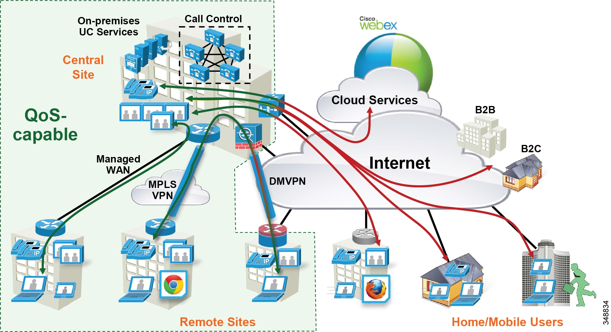
The collaboration landscape is constantly evolving, and two areas that have changed dramatically are the applications and the network. When Unified Communications was first introduced, it consisted primarily of fixed hardware endpoints such as IP phones and room system endpoints connected to a completely managed network where the administrators were able to implement Quality of Service (QoS) everywhere throughout the network where media traversed. Over time, usage of the Internet and cloud-based services such as WebEx have been added, which means that some of the collaboration infrastructure is now located outside of the managed network and in the cloud. The office connectivity options have also evolved, and companies are interconnecting remote sites and mobile users over the Internet either directly connected over Cisco Expressway, for example, or over technologies such as Dynamic Multipoint VPN (DMVPN). Figure 13-1 illustrates the convergence of a traditional on-premises Collaboration solution in a managed (capable of QoS) network with cloud services and sites located over an unmanaged (not capable of QoS) network such as the Internet. On-premises remote sites are connected over this managed MPLS network where administrators can prioritize collaboration media and signaling with QoS, while other remote sites and branches connect into the enterprise over the Internet, where collaboration media and signaling cannot be prioritized or can be prioritized only outbound from the site. Many different types of mobile and teleworkers also connect over the Internet into the on-premises solution. So the incorporation of the Internet as a source for connecting the enterprise with remote sites, home and mobile users, as well as other businesses and consumers, is becoming pervasive and has an important impact on bandwidth management and user experience.
Figure 13-1 Managed versus Unmanaged Network
New technologies and trends also mean an evolution of endpoints and user experiences and a plethora of collaboration devices and options. The enterprise is moving from housing single-purpose, single-media communications devices to multi-purpose, multi-media options. This is evident in trends such as Bring Your Own Device (BYOD), where users are bringing to the enterprise their compact and powerful mobile devices and incorporating collaboration technologies such as instant messaging, video collaboration and conferencing, and desktop sharing, to name a few, into their work processes, making them more collaborative and efficient.
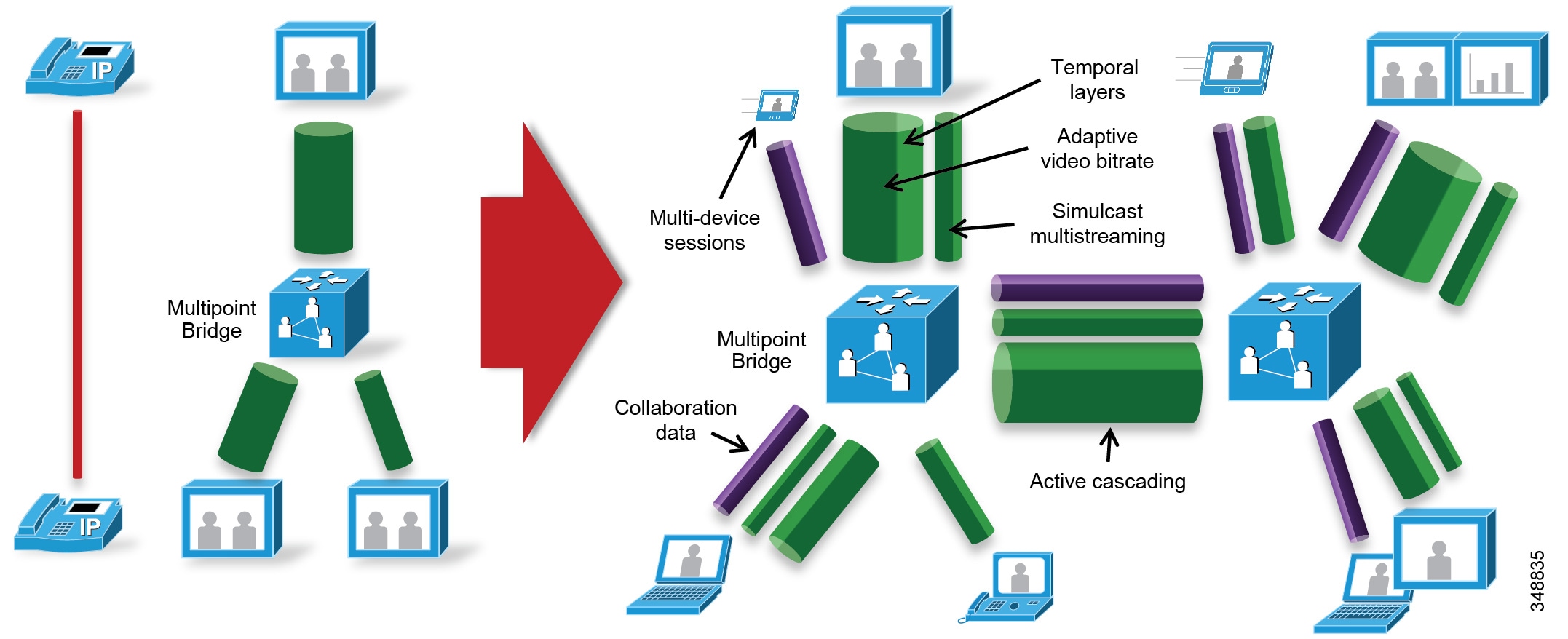
Collaboration media has also greatly evolved from fixed single-stream, fixed bit rate audio and video streams connected point-to-point or via a multi-point bridge to multi-layer, multi-stream, adaptive bit rate video sessions cascaded across multi-point bridges interconnecting a variety of devices. Figure 13-2 illustrates this evolution.
Figure 13-2 The Evolution of Collaboration Media Streams
Other technologies and trends that are currently and actively being adopted in the collaboration solution include:
- Mobility, Bring Your Own Device (BYOD), and ubiquitous video
- Web-based collaboration and WebRTC
- Standard versus immersive video
- Cloud, on-premises, and hybrid conferencing
- Wide-area networks: owned versus over-the-top
- Inter-company collaboration: business-to-business and business-to-consumer
- Multi-device, multi-stream sessions: voice, video, data sharing, and instant messaging
This evolution of managed versus unmanaged networks, new endpoints, and user experiences as well as new technologies and trends have brought with them challenges such as:
- How to manage the bandwidth and ensure a high-quality user experience over managed and unmanaged networks
- How to deploy video pervasively across the enterprise and optimize bandwidth utilization of the available network resources
This chapter presents a strategy of leveraging smart media techniques in Cisco Video endpoints, building an end-to-end QoS architecture, and using the latest design and deployment recommendations and best practices for managing bandwidth to achieve the best user experience possible based on the network resources available and the types of networks collaboration media are now forced to traverse.
Collaboration Media
This section covers the characteristics of audio and video streams in real-time media, as well as the smart media techniques that Cisco Video endpoints employ to ensure high fidelity video in the face of packet loss, delay, and jitter.
Fundamentals of Digital Video
Video is a major component of the enterprise traffic mix. Both streaming and pre-positioned video have implications on the network that can substantially affect overall performance. Understanding the structure of video datagrams and the requirements they place on the network can assist network administrators with implementing a media-ready network.
Different Types of Video
There are several broad attributes that can be used to describe video. For example, video can be categorized as real-time or prerecorded, streaming or pre-positioned, and high resolution or low resolution. The network load is dependent on the type of video being sent. Prerecorded, pre-positioned, low resolution video is little more than a file transfer, while real-time streaming video demands a high-performance network. Many generic video applications fall somewhere in between. This allows non-real-time streaming video applications to work acceptably over the public Internet. Tuning the network and media encoders is an important aspect of deploying video on an IP network.
H.264 Coding and Decoding Implications
Video codecs have been evolving over the last 15 years. Today's codecs take advantage of the increased processing power to better optimize the stream size. The general procedure has not changed much since the original MPEG1 standard was released. Pictures consist of a matrix of pixels that are grouped into blocks. Blocks combine into macro blocks. A row of macro blocks is a slice. Slices form pictures, which are combined into groups of pictures (GOPs).
Each pixel has a red, green, and blue component. The encoding process starts by color sampling the RGB into a luma and two-color components, commonly referred to as YCrCb. Small amounts of color information can be ignored during encoding and then replaced later by interpolation. Once in YCrCb form, each component is passed through a transform. The transform is reversible and does not compress the data. Instead, the data is represented differently to allow more efficient quantization and compression. Quantization is then used to round out small details in the data. This rounding is used to set the quality. Reduced quality allows better compression. Following quantization, lossless compression is applied by replacing common bit sequences with binary codes. Each macro block in the picture goes through this process, resulting in an elementary stream of bits. This stream is sliced into 188-byte packets known as a Packetized Elementary Stream (PES). This stream is then loaded into IP packets. Because IP packets have a 1,500 byte MTU and PES packets are fixed at 188 bytes, only 7 PES can fit into an IP packet. The resulting IP packet will be 1,316 bytes, not including headers. As a result, IP fragmentation is not a concern. An entire frame of high definition video may require 100 IP packets to carry all of the elementary stream packets, although 45 to 65 packets are more common. Quantization and picture complexity are the primary factors in determining the number of packets required for transmission. Forward error correction can be used to estimate some lost information. However, in many cases multiple IP packets are dropped in sequence. This makes the frame almost impossible to decompress. The packets that were successfully sent represent wasted bandwidth. RTCP can be used to request a new frame. Without a valid initial frame, subsequent frames will not decode properly.
Frame Types
The current generation of video coding is known by three names; H.264, MPEG4 part 10, and Advanced Video Coding (AVC). As with earlier codecs, H.264 employs spatial and temporal compression. Spatial compression is used on a single frame of video as described previously. These types of frames are known as I-frames. An I-frame is the first picture in a GOP. Temporal compression takes advantage of the fact that little information changes between subsequent frames. Changes are a result of motion, although changes in zoom or camera movement can result in almost every pixel changing. Vectors are used to describe this motion and are applied to a block. A global vector is used if the encoder determines all pixels moved together, as is the case with camera panning. In addition, a difference signal is used to fine-tune any error that results. H.264 allows variable block sizes and is able to code motion as fine as ¼ pixel. The decoder uses this information to determine how the current frame should look based on the previous frame. Packets that contain the motion vectors and error signals are known as P-frames. Lost P-frames usually results in artifacts that are folded into subsequent frames. If an artifact persists over time, then the likely cause is a lost P-frame.
Figure 13-3 illustrates how this works in a basic manner:
1.![]() An I-frame (Intra-coded picture) is the entire picture encoded as a static image and sent as a group of packets. This frame does not reference any other frame, and the decoder requires only this frame to build the entire image. In this case the image is of a little hiker hiking through the mountains.
An I-frame (Intra-coded picture) is the entire picture encoded as a static image and sent as a group of packets. This frame does not reference any other frame, and the decoder requires only this frame to build the entire image. In this case the image is of a little hiker hiking through the mountains.
2.![]() Next a P-frame (Predicted picture) is sent, which is a frame based on a previously encoded frame (in this case the I-frame), and only the differences from that I-frame are encoded. The decoder takes these differences and applies them to the I-frame that it had. In this case it shows the little hiker moving up the hill. Because only the little hiker and his movement have changed from the last I-frame, this P-frame is much smaller and represents fewer packets and thus less bandwidth to be transmitted.
Next a P-frame (Predicted picture) is sent, which is a frame based on a previously encoded frame (in this case the I-frame), and only the differences from that I-frame are encoded. The decoder takes these differences and applies them to the I-frame that it had. In this case it shows the little hiker moving up the hill. Because only the little hiker and his movement have changed from the last I-frame, this P-frame is much smaller and represents fewer packets and thus less bandwidth to be transmitted.
3.![]() The next P-frame is sent and is a prediction from the last P-frame sent. As in the P-frame from step 2, this P-frame shows the difference between the last movement of the hiker up the hill and this new movement of the hiker. This progression continues until there is a larger amount of change from the previous image, thus requiring a new I-frame.
The next P-frame is sent and is a prediction from the last P-frame sent. As in the P-frame from step 2, this P-frame shows the difference between the last movement of the hiker up the hill and this new movement of the hiker. This progression continues until there is a larger amount of change from the previous image, thus requiring a new I-frame.
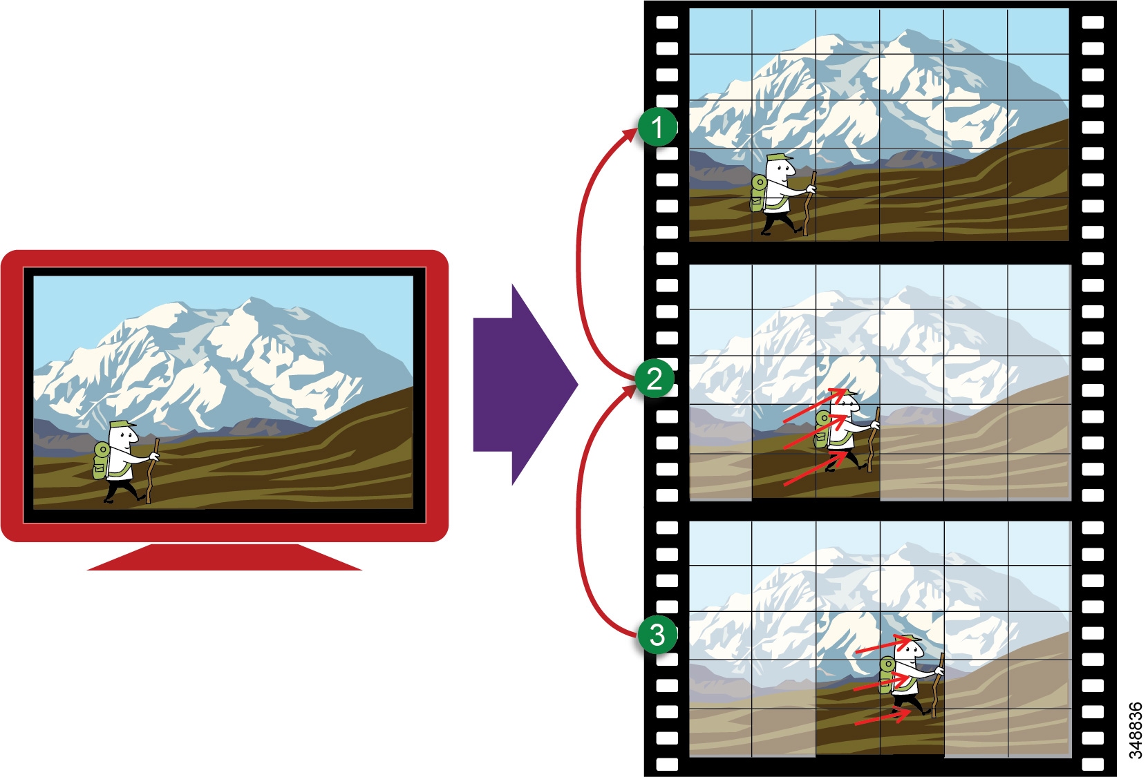
H.264 also implements B-frames. This type of frame fills in information between P-frames. This means that the B-frame must be held until the next P-frame arrives, before the B-frame information can be used. B-frames are not used in all modes of H.264. The encoder decides what type of frame is best suited. There are typically more P-frames than I-frames. Lab analysis has shown TelePresence I-frames to generally be 64 Kbytes wide (50 packets @ 1,316 bytes), while P-frames average 8 Kbytes wide (9 packets at 900 bytes). So I-frames are larger and create the spikes in bit rate in comparison to P-frames.
Audio versus Video
Voice and video are often thought of as close cousins. Although they are both real-time protocol (RTP) applications, the similarities stop there. Voice is generally considered well behaved because each packet is a fixed size and fixed rate. Video frames are spread over multiple packets that travel as a group. Because one lost packet can ruin a P-frame, and one bad P-frame can cause a persistent artifact, video generally has a tighter loss requirement than audio. Video is asymmetrical. Voice can also be asymmetrical but typically is not. Even on mute, an IP phone will send and receive the same size flow.
Video increases the average real-time packet size and has the capacity to quickly alter the traffic profile of networks. Without planning, this could be detrimental to network performance. Figure 13-4 shows the difference between a series of audio packets and a series of video packets sent over a specific time interval.
Figure 13-4 Audio versus Video
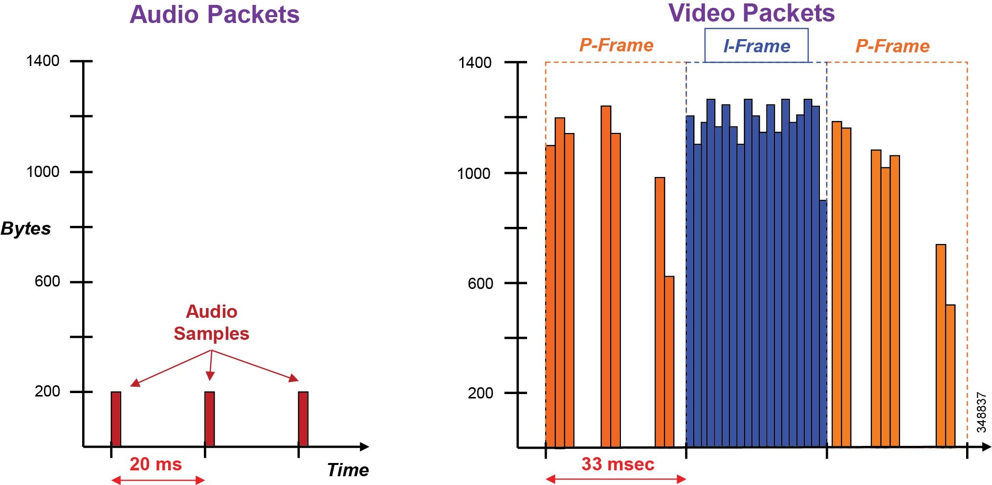
As can be seen from Figure 13-4, the audio packets are the same size, sent at exactly the same time intervals, and they represent a very smooth stream. Video, on the other hand, sends a larger group of packets over fixed intervals and can vary greatly from frame to frame. Figure 13-4 shows the difference in the number of packets and packet sizes for an I-frame as opposed to P-frames. This translates to a stream of media that is very bursty in nature when compared to audio. Figure 13-5 illustrates the bandwidth profile over time of an HD video stream. Note the large bursts when I-frames are sent.
Figure 13-5 Bandwidth Usage: High-Definition Video Call
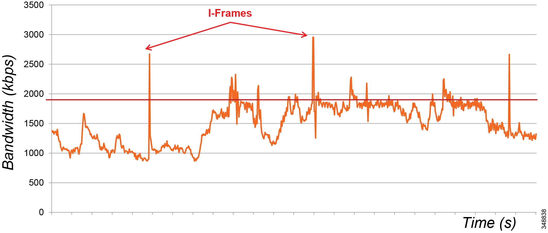
Figure 13-5 shows an HD video call, 720p30 @ 1,920 kbps (1,792 kbps video + 128 kbps audio). The graph shows the video bandwidth (including L3 overhead), and the red line indicates average bit rate.
While audio and video are both transported over UDP and sensitive to loss and delay, they are quite different in their network requirements and profile. Audio is a constant bit rate and has a smaller footprint compared to video, as well as a narrower operational range of 1:6 ratio when comparing the lowest bit-rate audio codec to one of the highest bit-rate codecs. Video, on the other hand, has a variable bit rate (is bursty) and has a medium to large footprint when compared to audio, as well as a wide operational range of 1:40 (250p at 15 fps vs 1080p at 60 fps). Figure 13-6 illustrates some of these differences.
Figure 13-6 Video Traffic Requirements and Profiles
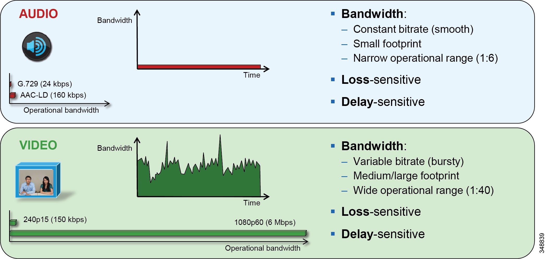
The important point to keep in mind is that audio and video, while similar in transport and sensitivity to loss and delay, are quite different with regard to managing their bandwidth requirements in the network. It should also be noted that, while video is pertinent to a full collaboration experience, audio is critical. If, for example, video is lost during a video call due to a network outage or some other network related event, communication can continue provided that audio is not lost during this outage. This is a critical concept when thinking through the network requirements of a collaboration design such as QoS classification and marking.
Resolution
The sending station determines the video resolution and, consequently, the load on the network. This is irrespective of the size of the monitor used to display the video. Observing the video is not a reliable method to estimate load. Common high definition formats are 720i, 1080i, 1080p, and so forth. In addition to high resolution, there is also a proliferation of lower quality video that is often tunneled in HTTP (or in some cases HTTPS) and SSL (see Table 13-2 ). Typical resolutions include CIF (352x288) and 4CIF (704x576). These numbers were chosen as integers of the 16x16 macro blocks that are used by the DCT (22x18) and (44x36) macro blocks respectively.
|
|
|
|
|---|---|---|
Network Load
The impact of resolution on the network load is generally a squared factor; an image that is twice as big will require four times the bandwidth. In addition, the color sampling, quantization, and frame rate also impact the amount of network traffic. Standard rates are 30 frames per second (fps), but this is an arbitrary value chosen based on the frequency of AC power. In Europe, analog video is traditionally 25 fps. Cineplex movies are shot at 24 fps. As the frame rate decreases, the network load also decreases and the motion becomes less life-like. Video above 24 fps does not noticeably improve motion.
The sophistication of the encoder also has a large impact on video load. H.264 encoders have great flexibility in determining how best to encode video, and with this comes complexity in determining the best method. For example, MPEG4.10 allows the encoder to select the most appropriate block size depending on the surrounding pixels. Because efficient encoding is more difficult than decoding, and because the sender determines the load on the network, low-cost encoders usually require more bandwidth than high-end encoders. H.264 coding of real-time CIF video will drive all but the most powerful laptops well into 90% CPU usage without dedicated media processors.
Table 13-3 through Table 13-5 show average bandwidth utilization ranges based on endpoint and resolution. These tables are provide only as an example of the bandwidth ranges based on resolution of common TelePresence and desktop video endpoints. Refer to the current product documentation for the latest numbers relevant to the endpoints in question.
|
|
|
|
|
|
||||
|---|---|---|---|---|---|---|---|---|
|
|
|
|
|
|
|
|
|
|
|
1.For more information on TelePresence endpoints, refer to the bandwidth usage white paper available at http://www.cisco.com/c/dam/en/us/products/collateral/collaboration-endpoints/tested_bandwidth_whitepaperx.pdf. |
|
|
|
|---|---|
|
2.For more information on the DX Series, refer to the latest version of the Cisco DX Series Administration Guide, available at http://www.cisco.com/c/en/us/support/collaboration-endpoints/desktop-collaboration-experience-dx600-series/products-maintenance-guides-list.html. |
|
|
|
|---|---|
|
3.For more information on Jabber, refer to the latest version of the Cisco Jabber Deployment and Installation Guide, available at http://www.cisco.com/c/en/us/support/unified-communications/jabber-windows/products-installation-guides-list.html. |
Multicast
Broadcast video lends itself well to taking advantage of the bandwidth savings offered by multicast. This has been in place in many networks for years. Recent improvements to multicast simplify the deployment on the network. Multicast will play a role going forward; however, multicast is not used in all situations. Some applications such as multipoint TelePresence use a dedicated MCU to replicate video. The MCU can make decisions concerning which participants are viewing each sender. The MCU can also quench senders that are not being viewed.
Transports
MPEG4 uses the same transport as MPEG2. A PES consists of 188-byte datagrams that are loaded into IP. The video packets can be loaded into RTP/UDP/IP or HTTP(S)/TCP/IP.
Video over UDP is found with dedicated real-time applications such as multimedia conferencing and TelePresence. In this case, an RTCP channel can be set up from the receiver toward the sender. This is used to manage the video session. RTCP can be used to request I-frames or report capabilities to the sender. UDP and RTP each provide a method to multiplex channels. Audio and video typically use different UDP ports but also have unique RTP payload types. Deep packet inspection (DPI) can be used on the network to identify the type of video and audio that is present. Note that H.264 also provides a mechanism to multiplex layers of the video.
Buffering
Jitter and delay are present in all IP networks. Jitter is the variation in delay. Delay is generally caused by interface queuing. Video decoders can employ a play-out buffer to smooth out jitter found in the network. There are limitations to the depth of this buffer. If it is too small, then drops will result. If it is too deep, then the video will be delayed, which could be a problem in real-time applications such as TelePresence. Another limitation is handling dropped packets that often accompany deep play-out buffers. If RTCP is used to request a new I-frame, then more frames will be skipped at the time of re-sync. The result is that dropped packets have a slightly greater impact in video degradation than they would have if the missing packet had been discovered earlier. Most codecs employ a dynamic play-out buffer.
Summary
Video can dramatically impact the performance of the network if planning does not properly account for this additional load. This chapter attempts to assist administrators in managing real-time video in enterprise networks.
"Smart" Media Techniques (Media Resilience and Rate Adaptation)
Cisco enterprise video endpoints have evolved greatly over the last few years. Every Cisco video endpoint employs a number of media resiliency techniques to avoid network congestion, recover from packet loss, and optimize network resources. This section covers the following smart media techniques employed by Cisco video endpoints:
Encoder Pacing
The number of packet can increase dependent on the frame type (I or P) as well as the number of packets required, which means that bursts of packets can show up at the beginning, middle, or end of a 33 ms time interval. This creates spikes in bandwidth as the packets are put onto the wire. Encoder pacing is a simple technique used to spread the packets as evenly as possible across the 33 ms interval in order to smooth out the peaks of the bursts of bandwidth. Figure 13-7 illustrates this technique.
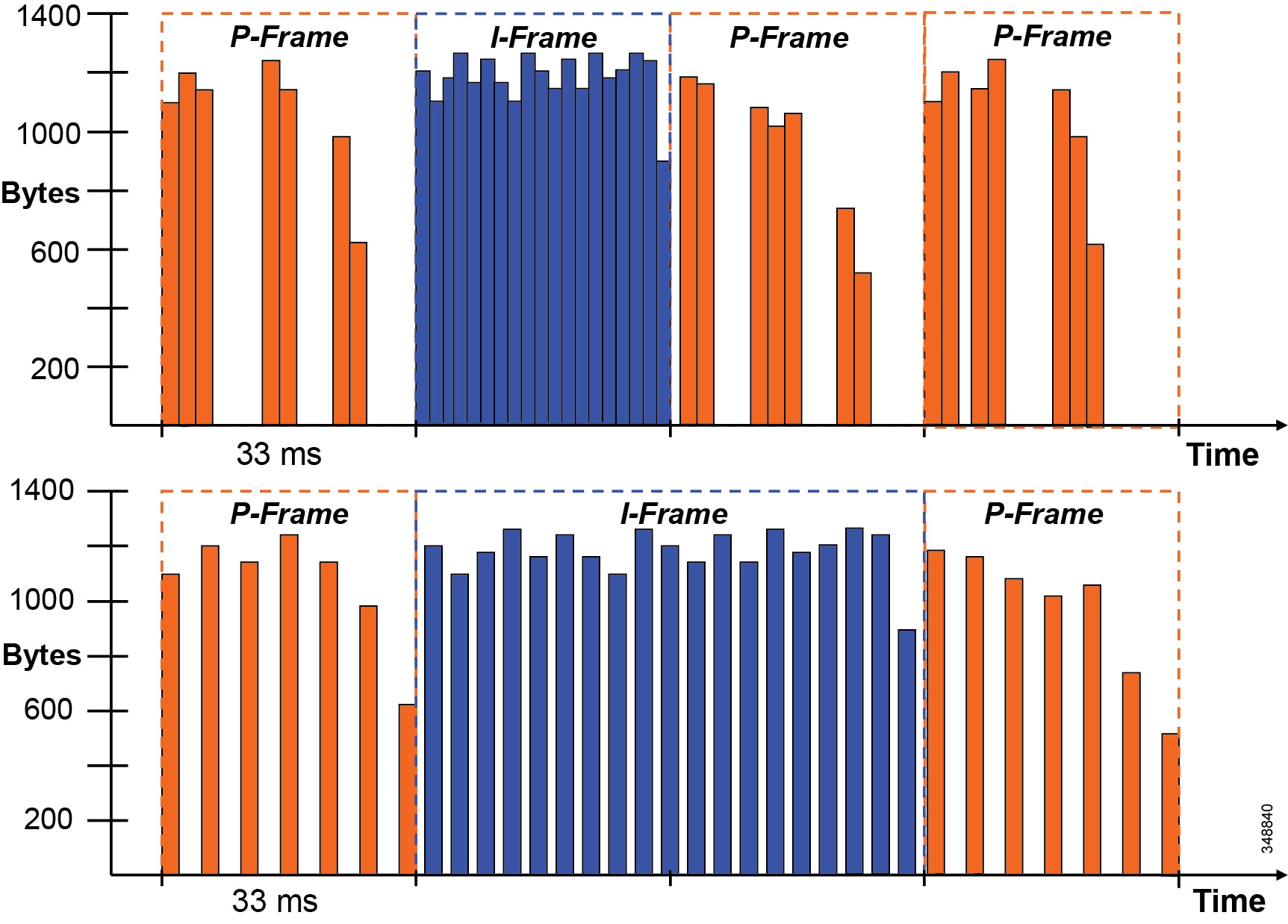
The top image in Figure 13-7 shows packets being placed on the wire without encoder pacing, and the bottom image is with encoder pacing. As each frame is packetized onto the wire in a 33 ms interval, an endpoint packet scheduler disperses packets as evenly as possible across that single interval. Large I-frames might have to be "spread" over two or three frame intervals, and the encoder might then skip one or two frames to stay within a bit rate budget. This smooths out the peaks in bandwidth utilization over the same time frame.
Gradual Decoder Refresh (GDR)
GDR provides a starting point or refresh of the encoded bit stream. GDR is a method of gradually refreshing the picture over a number of frames, giving a smoother and less bursty bit stream.
A new I-frame causes a traffic burst, which in turn can generate congestion, particularly in switched conferences. If one I-frame packet gets dropped, the whole frame needs to be retransmitted. As illustrated in Figure 13-8, Gradual Decoder Refresh spreads "intra"-encoded picture data over N frames. The GDR frames contain a portion of "intra" macroblocks and a portion of predicted macroblocks. Once all GDR frames have been received, the decoder can fully refresh the picture.
Figure 13-8 Gradual Decoder Refresh (GDR)

Long Term Reference Frame (LTRF)
A Long Term Reference Frame (LTRF) is a reference frame that is stored in the encoder and decoder until they receive an explicit signal to do otherwise. (Up to 15 LTRFs are supported by H.264.) Typically (without LTRF) an intra-frame is used for encoder/decoder resynchronization after packet loss.
LTRFs can provide benefits over normal infra-frames as an alternative method for encoder/decoder resynchronization. Typically, the encoder inserts LTRFs periodically and at the same time instructs the decoder to store one or more of those LTRFs (see Figure 13-9).
A repair P-frame uses a previous LTRF that has been decoded correctly as a reference. The repair P-frame is used in response to a missing frame or its reference frame. Because the acknowledged LTRF is known to have been correctly received at the decoder, the decoder is known to be back in-sync if it can correctly decode a repair P-frame.
Figure 13-9 Long Term Reference Frame (LTRF)

As Figure 13-9 illustrates, LTRFs keep the encoder and decoder in sync with active feedback messages. The encoder instructs the decoder to store raw frames at specific sync points as Long Term Reference Frames (part of the H.264 standard), and the decoder uses "back channel" (RTCP) to acknowledge the LTRFs. When a frame is lost, the encoder creates a Repair P-frame based on the last synchronized LTRF instead of generating a new I-frame, thus saving bandwidth.
Forward Error Correction (FEC)
Forward error correction (FEC) provides redundancy to the transmitted information by using a predetermined algorithm (see Figure 13-10). The redundancy allows the receiver to detect and correct a limited number of errors occurring anywhere in the message, without the need to ask the sender for additional data. FEC gives the receiver an ability to correct errors without needing a reverse channel to request retransmission of data, but this advantage is at the cost of a fixed higher forward channel bandwidth. FEC protects the most important data (typically the repair P-frames) to make sure the receiver is receiving those frames. The endpoints do not use FEC on bandwidths lower than 768 kbps, and there must also be at least 1.5% packet loss before FEC is introduced. Endpoints typically monitor the effectiveness of FEC, and if FEC is not efficient, they make a decision not to do FEC.
Figure 13-10 Forward Error Correction (FEC)
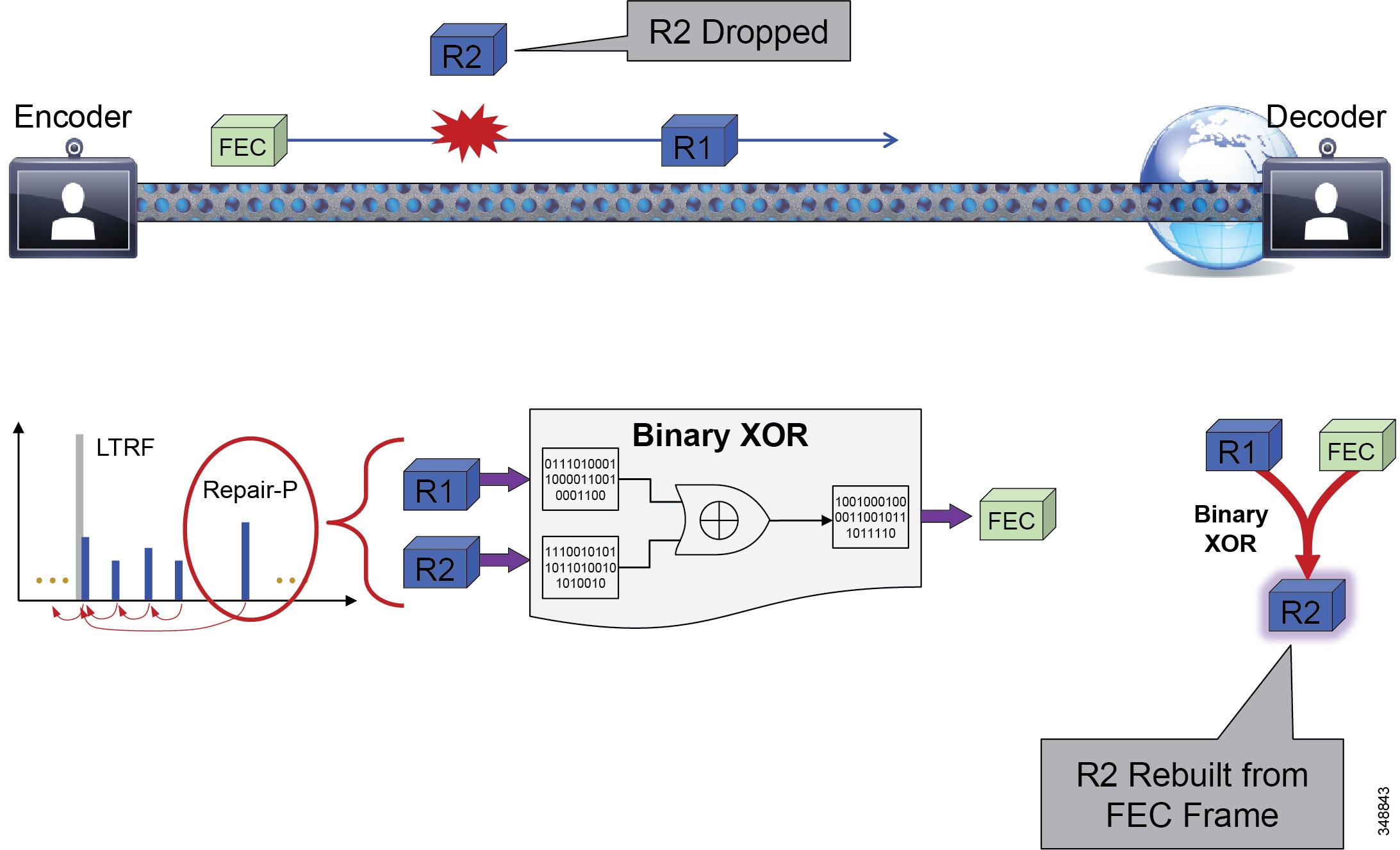
As Figure 13-10 illustrates, FEC enables the decoder to recover from a limited amount of packet loss without losing synchronization. It can be applied at different levels (for example, X FEC packets every N data packets) to protect "important" frames in lossy environments. The correction code can be basic (binary XOR) or more advanced (Reed-Solomon). The trade-off is increased bandwidth usage, therefore it is best suited for non-bursty loss.
Rate Adaptation
Rate adaptation, or dynamic bit rate adjustments, adapt the call rate to the variable bandwidth available, down-speeding or up-speeding the video bit rate based on the packet loss condition (see Figure 13-11). Once the packet loss has decreased, up-speeding will occur. Some endpoints use a proactive sender-initiated approach by utilizing RTCP. In this case the sender is constantly reviewing the RTCP receiver reports and adjusting its bit rate accordingly. Other endpoints use a receiver-initiated approach, adjusting via call signaling (H.323 flow control, TMBRR, SIP Re-invite) or an explicit request in the RTCP messages.
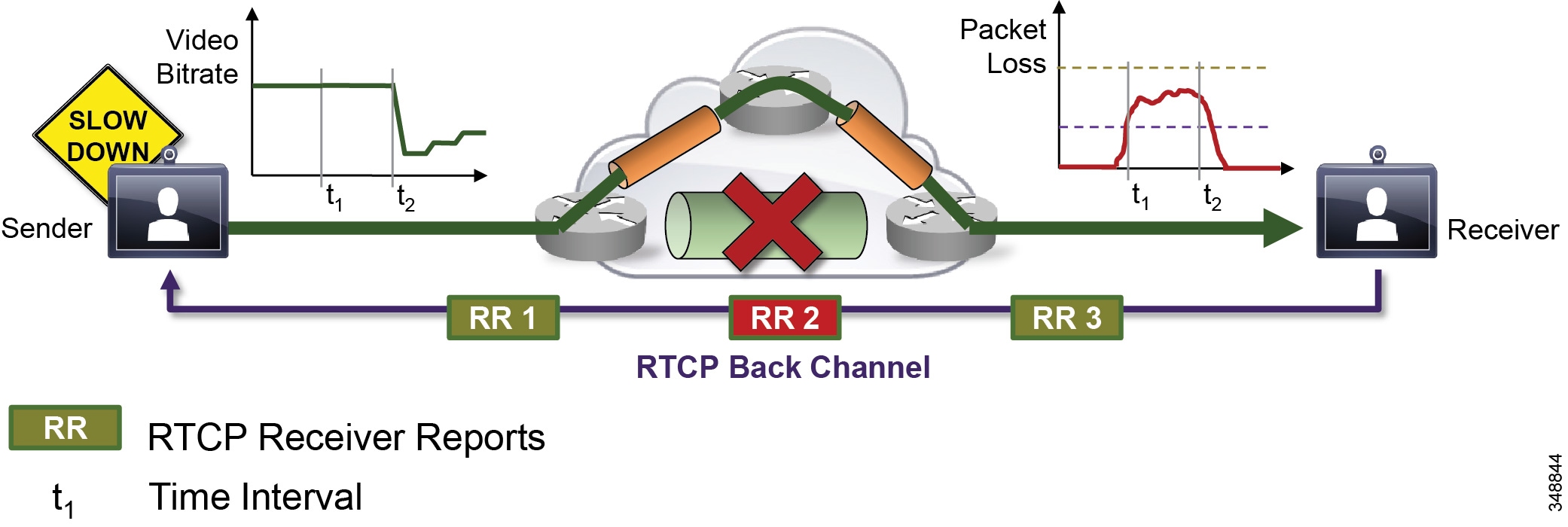
As illustrated in Figure 13-11, the receiver observes delay and packet loss over periods of time and signals back using RTCP Receiver Reports (RR). the reports cause the sender to adjust its bit rate to adapt to network conditions (down-speeding or up-speeding of bit rate).
Summary
- Burstiness of traffic and mobility of the endpoints make deterministic provisioning for interactive video difficult for network administrators.
- Media resiliency mechanisms help mitigate the impact of video traffic on the network and the impact of network impairments on video. (See Table 13-6 .)
- Dynamic rate adaptation creates an opportunity for more flexible provisioning models for interactive video in enterprise networks.
- Media resiliency and rate adaptation also help preserve the user experience when video traffic traverses the Internet or non-QoS-enabled networks.
|
|
|
|
|
|
|---|---|---|---|---|
QoS Architecture for Collaboration
Quality of Service (QoS) ensures reliable, high-quality voice and video by reducing delay, packet loss, and jitter for media endpoints and applications. QoS provides a foundational network infrastructure technology that is required to support the transparent convergence of voice, video, and data networks. With the increasing amount of interactive applications (particularly voice, video, and immersive applications), real-time services are often required from the network. Because these resources are finite, they must be managed efficiently and effectively. If the number of flows contending for such priority resources were not limited, then as these resources become oversubscribed, the quality of all real-time traffic flows would degrade, eventually to the point of become useless. "Smart" media techniques, QoS, and admission control ensure that real-time applications and their related media do not over-subscribe the network and the bandwidth provisioned for those applications. These smart media techniques coupled with QoS and, where needed, admission control, can be a powerful set of tools to protect real-time media from non-real-time network traffic and protect the network from over-subscription and the potential loss of quality of experience for all voice and video applications.
Admission control and QoS are complementary. Admission control requires QoS, but QoS may be deployed without admission control. Later in this chapter, admission control and its relationship to QoS are discussed further.
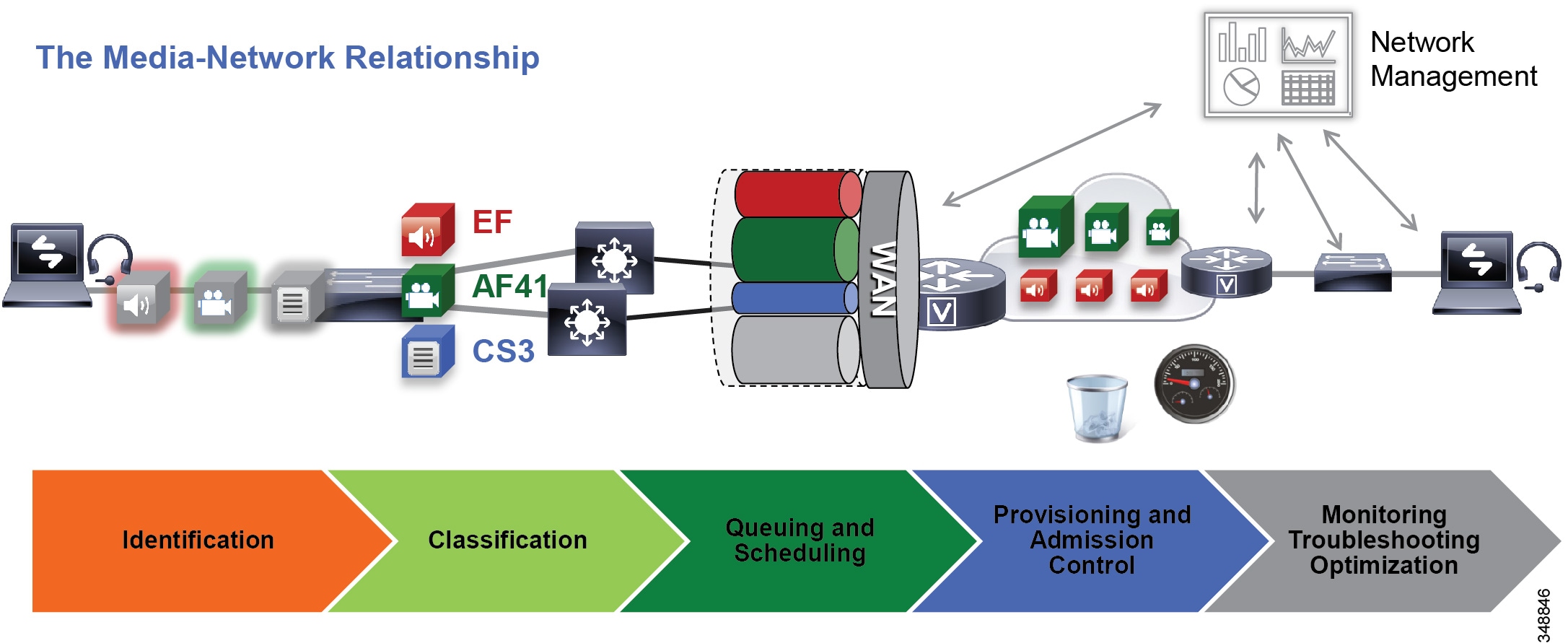
Figure 13-12 illustrates the approach to QoS used in this chapter. This approach consists of the following phases, discussed further in the sections that follow:
This phase involves the concepts of trust and techniques for identifying media and signaling for trusted and untrusted endpoints. It includes the process of mapping the identified traffic to the correct DSCP to provide the media and signaling with the correct per-hop behavior end-to-end across the network for both trusted and untrusted endpoints.
This phase consists of general WAN queuing and scheduling, the various types of queues, and recommendations for ensuring that collaboration media and signaling are correctly queued on egress to the WAN.
This phase involves provisioning of bandwidth in the network and determining the maximum bit rate that groups of endpoints will utilize. This is also where call admission control can be implemented in areas of the network where it is required.
This phase is crucial to the proper operation and management of voice and video across the network; however, it is not discussed in this chapter. For information on these tasks, see the chapter on Network Management.
Figure 13-12 Elements of the QoS Architecture for Collaboration
Identification and Classification
This section discusses the concepts of trust and techniques for identifying media and signaling for trusted and untrusted endpoints. It includes the process of mapping the identified traffic to the correct DSCP to provide the media and signaling with the correct per-hop behavior end-to-end across the network for both trusted and untrusted endpoints.
QoS Trust and Enforcement
The enforcement of QoS is crucial to any real-time audio, video, or immersive video experience. Without the proper QoS treatment (classification, prioritization, and queuing) through the network, real-time media can potentially incur excessive delay or packet loss, which compromises the quality of the real-time media flow. In the QoS enforcement paradigm, the issue of trust and the trust boundary is equally important. Trust refers to the endpoint or device permitting or "trusting" the QoS marking (Layer 2 CoS or Layer 3 IP DSCP) of the traffic and allowing it to continue through the network. The trust boundary is the place in the network where the trust occurs. It can occur at any place in the network, but we recommend enforcing trust at the network edge, such as the LAN access ingress or the WAN edge or both if feasible and applicable. The WAN edge is another area of traffic ingress, and sometimes service providers re-mark traffic for usage throughout their network (service provider network). Because of this situation, it is important to re-mark the traffic back to the appropriate values to ensure continuity through the enterprise network end-to-end.
In a Cisco converged network with Cisco IP phones and video endpoints, switches can be configured to detect the phones using Cisco Discovery Protocol (CDP), and the switch can then trust the Differentiated Services Code Point (DSCP) marking of packets that the Cisco IP phones and video endpoints send without trusting the markings of the PC connected to the switch port of the IP phone or video endpoint. This is referred to as conditional trust and is commonplace in protected VLANs where only Cisco IP phones are admitted (referred to as voice VLANs) and where their packet marking is trusted by the switches and passed through the network unchanged. Administrators generally do not trust the traffic that comes from VLANs where untrusted clients (such as PCs or Macs) are typically located (referred to as data VLANs). The packets that come from devices in the data VLAN or equivalent areas of the network typically get remarked to best effort (IP DSCP 0).
From a trust perspective, there are three main categories of endpoints:
- Untrusted endpoints — Unsecure PCs, Macs, or hand-held mobile devices
- Trusted endpoints — Secure PCs and servers, video conferencing endpoints, access points, analog and video conferencing gateways, and other similar devices where CDP is not available
- Conditionally trusted endpoints — Cisco IP phones as well as Cisco TelePresence endpoints that support CDP
Figure 13-13 illustrates these three types of devices.
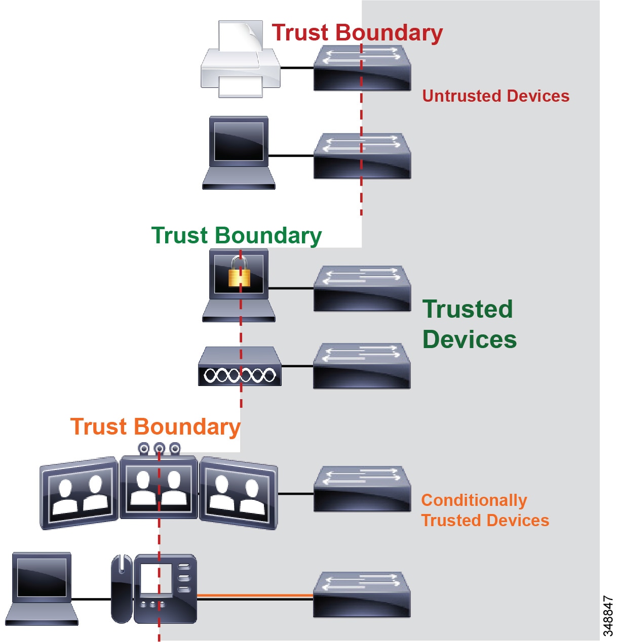
The trust boundary should be set as close to the endpoints as technically and administratively feasible. The recommendation is to set trust on the switch and use voice VLANs for collaboration media and signaling, and use data VLANs for non-collaboration data traffic. See the section on Campus Access Layer, for more information on Layer 2 access design.
Classification and Marking
Once the trust boundary is established, QoS enforcement can be put into place for two categories of devices: trusted and untrusted. This section discuss classification and marking for trusted and untrusted devices.
For trusted and conditionally trusted endpoints, the DSCP marking of packets on ingress into the switch are trusted and rewritten to the same value on egress. Figure 13-14 illustrates marking of audio, video, and signaling traffic for trusted endpoints, and the switch trusting these markings.
Figure 13-14 Trusted Endpoint Re-marking
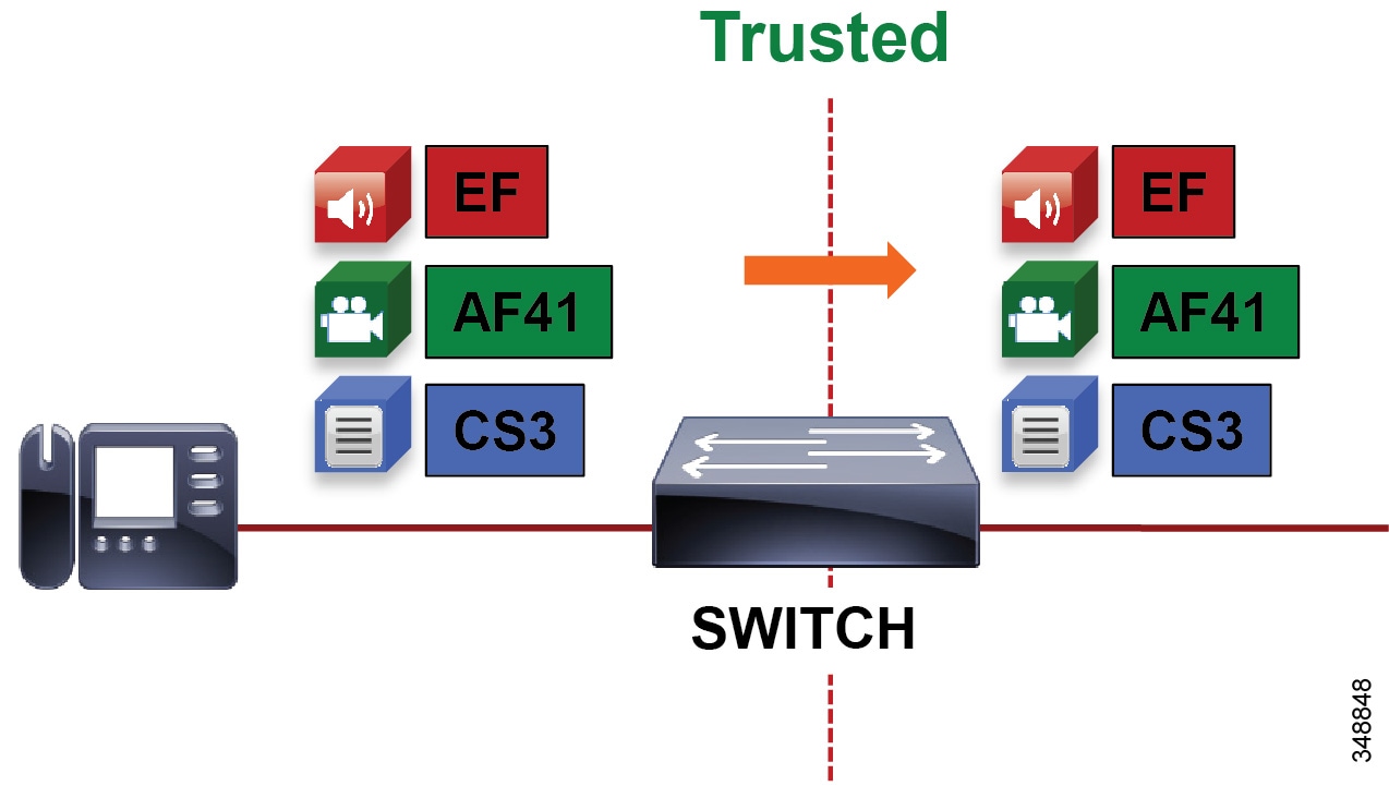
For Cisco switches configured with trusted or conditionally trusted ports, the switch either uses CoS to map to DSCP or it uses the original DSCP and maps it to the outbound packet IP header DSCP. Figure 13-15 illustrates the inbound packet marking at Layer 2 (CoS) and Layer 3 (DSCP); the type of trust – trusted (CoS Trust or DSCP Trust) or untrusted; and the internal switch packet rewriting process based on CoS trust or DSCP trust.
Figure 13-15 Inbound and Outbound Switch Packet Marking
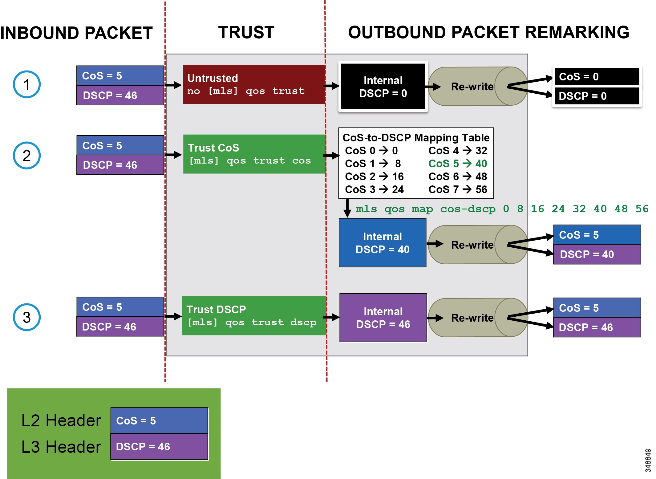
Multi-Layer Switching (MLS) commands are used in Figure 13-15 as an example only. MLS platforms include the Cisco 2960, 3560, and 3750 Series switch platforms. On all other currently shipping switch platforms (including the Cisco 3650, 3850, 4500, 6500, and 6800 Series switch platforms) trust is enabled by default.
Figure 13-15 shows three events:
1.![]() A packet marked CoS 5 and DSCP 46 comes inbound on an untrusted port. An internal DSCP of 0 (BE) is used to rewrite the outbound packet CoS and DSCP to 0.
A packet marked CoS 5 and DSCP 46 comes inbound on an untrusted port. An internal DSCP of 0 (BE) is used to rewrite the outbound packet CoS and DSCP to 0.
2.![]() A packet marked CoS 5 and DSCP 46 comes inbound on a trusted port (CoS trust). A lookup is done on a CoS-to-DSCP mapping table to map CoS 5 to an internal DSCP of 40. An internal DSCP of 40 is used to rewrite the outbound packet CoS to 5 and DSCP to 40. Note that the CoS-to-DSCP map table has defaults but can be modified to any static CoS-to-DSCP mapping. For example, CoS 5 could be mapped to DSCP 46.
A packet marked CoS 5 and DSCP 46 comes inbound on a trusted port (CoS trust). A lookup is done on a CoS-to-DSCP mapping table to map CoS 5 to an internal DSCP of 40. An internal DSCP of 40 is used to rewrite the outbound packet CoS to 5 and DSCP to 40. Note that the CoS-to-DSCP map table has defaults but can be modified to any static CoS-to-DSCP mapping. For example, CoS 5 could be mapped to DSCP 46.
3.![]() A packet marked CoS 5 and DSCP 46 comes inbound on a trusted port (DSCP trust). An internal DSCP of 46 (EF) is used to rewrite the outbound packet CoS to 5 and DSCP to 46 (EF).
A packet marked CoS 5 and DSCP 46 comes inbound on a trusted port (DSCP trust). An internal DSCP of 46 (EF) is used to rewrite the outbound packet CoS to 5 and DSCP to 46 (EF).
For CDP-capable Cisco IP Phones, Cisco CTS, Cisco IP Video Surveillance cameras, and Cisco Digital Media Players (as opposed to software clients such as Jabber), we recommend using the CDP conditional trust and passing the marking of the trusted endpoint through the network. When electing to trust Cisco IP Phones, you must trust CoS because the phones can re-mark only PC traffic at Layer 2. Trusted endpoints derive their DSCP marking from Unified CM. DSCP for endpoints is configured in the Unified CM service parameters under Clusterwide Parameters (System - QoS).
Unified CM houses the QoS configuration for endpoints in two places: in the service parameters for the CallManager service and in the SIP Profile applicable only to SIP devices. The SIP Profile configuration of QoS settings overrides the service parameter configuration. This allows the Unified CM administrator to set different QoS policies for groups of endpoints (see Bandwidth Management Design Examples). During endpoint registration, Unified CM passes this QoS configuration to the endpoints in a configuration file over TFTP. This configuration file contains the QoS parameters as well as a number of other endpoint specific parameters. For QoS purposes there are two categories of video endpoints: TelePresence endpoints (any endpoint with TelePresence in the phone type name) and all other non-TelePresence video endpoints referred to as "UC Video Endpoints" in this document. Figure 13-16 illustrates how the two categories of Cisco video endpoints derive DSCP. Keep in mind that these categories apply only to QoS and call admission control (see the section on Enhanced Location CAC for TelePresence Immersive Video).
Figure 13-16 How Cisco Endpoints Derive DSCP
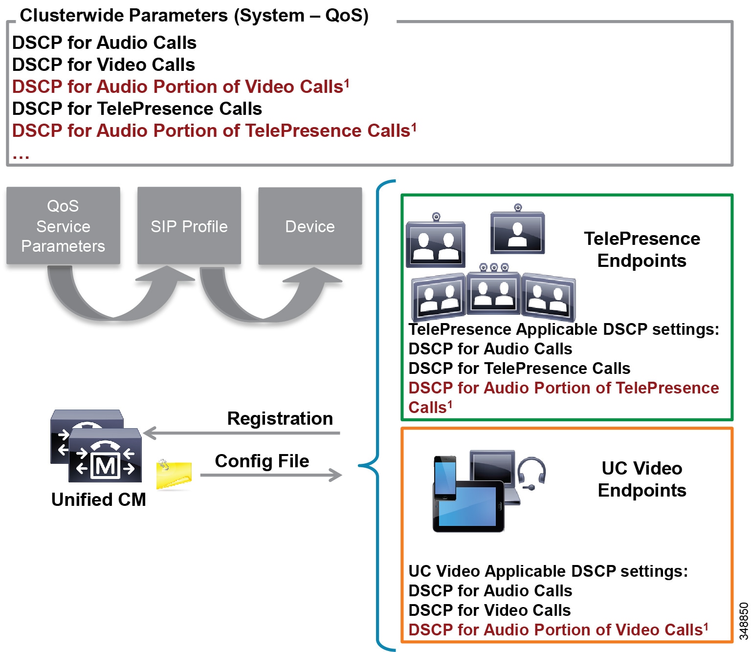
The parameters DSCP for Audio Portion of Video Calls and DSCP for Audio Portion of TelePresence Calls, shown in Figure 13-16, currently are not supported on all video endpoints. See Table 13-8 for information on which endpoint types support these parameters.
The configuration file is populated with the QoS parameters from the CallManager service parameters or the SIP Profile, when configured, and sent to the endpoint upon registration. The endpoint then uses the correct DSCP parameters for each type of media stream, depending on which category of endpoint it is. Table 13-7 lists the DSCP parameter, the type of endpoint, and the type of call flow determining the DSCP marking of the stream.
|
|
|
|
|
|---|---|---|---|
Video – Audio and video stream of a video call, unless the endpoint supports the DSCP for Audio Portion of Video Calls parameter |
|||
DSCP for Audio Portion of Video Calls5 |
Audio stream of a video call – Applicable only to endpoints that support this parameter |
||
Immersive video – Audio and video of an immersive video call, unless the endpoint supports the DSCP for Audio Portion of TelePresence Calls parameter. |
|||
DSCP for Audio Portion of TelePresence Calls 2 |
Audio stream of a video call – Applicable only to endpoints that support this parameter |
|
4.The DSCP settings for Multi-Level Priority and Preemption (MLPP) are not discussed here. For more information about MLPP and QoS settings, refer to the latest version of the System Configuration Guide for Cisco Unified Communications Manager. 5.This parameter is not currently supported on all video endpoints. See Table 13-8 for information on which endpoint types support this parameter. |
|
|
|
|
|---|---|---|
Yes6 |
||
Yes7 |
||
CE 8.x Software Series (DX70, DX80, SX Series, MX Series G2, MX700, MX800) |
||
| TC 7.1.4 Software Series (C Series, Profile Series, EX Series, MX Series G1) |
||
Due to these new features and system-wide capabilities, the current DSCP defaults are not always the recommended values. This is discussed in further detail in the Bandwidth Management Design Examples.
Untrusted Endpoints and Clients
For untrusted endpoints the DSCP marking of packets on ingress into the switch is untrusted and rewritten to 0 (BE). Figure 13-17 illustrates untrusted endpoints marking audio, video, and signaling traffic, and the switch rewriting this value on the outbound packet.
Figure 13-17 Untrusted Endpoint Re-marking
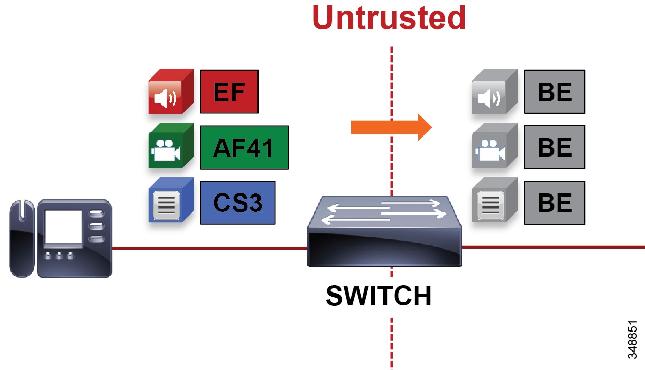
In general, trusting markings that can be set by users on their PCs, Macs, or hand-held mobile devices is not recommended. Users can abuse provisioned QoS policies if permitted to mark their own traffic (have administrative control of the OS). For example, if a DSCP of EF has been provisioned over the network, a PC user can configure all their traffic to be marked to EF, which will hijack network priority queues to service non-real-time traffic. Such abuse could easily ruin the service quality of real-time applications throughout the enterprise. On the other hand, if enterprise controls are in place that centrally administer PC QoS markings, such as Global Policy Objects in Windows environments, then it may be possible to trust the PC markings. For Macs running OSX and hand-held mobile clients, the question remains whether to trust the markings from them or not. This method is covered in more detail in the section "Utilizing the Operating System for QoS Trust, Classification and Marking". The general rule is not to trust any of these personal computing devices, and a method for re-marking traffic is required.
A different method from trust is required to ensure that the media and signaling streams from the software clients such as Jabber are able to get classified and marked appropriately. One method consists of mapping identifiable media and signaling streams based on specific protocol ports, such as UDP and TCP ports, then making use of network access lists to remark QoS of the signaling and media streams based on those protocol port ranges. This method applies to all Cisco Jabber clients because they all behave similarly when allocating media and signaling port ranges. This method ranges from using the network to create policies based on access lists to accomplish packet DSCP remarking, to using the Windows OS itself (Jabber for Windows clients only apply here) and then trusting the marking from the PC in the network.
This method is the most widely deployed and recommended method to achieve QoS with Cisco Jabber clients simply because of the trust issue. The Jabber clients are Cisco Jabber for Windows, Cisco Jabber for Mac OS, Cisco Jabber for iPhone, Cisco Jabber for iPad and Cisco Jabber for Android.
The concept is simple. As all of the traffic from the PC cannot be trusted, an access list is used in the network access layer equipment to identify the media and signaling streams based on UDP port ranges and to re-mark them to appropriate values. Although this technique is easy to implement and can be widely deployed, it is not a secure method.
Figure 13-18 illustrates using network access control lists (ACLs) to map identifiable media and signaling streams to DSCP.
Figure 13-18 Mapping UDP/TCP Port Ranges to DSCP
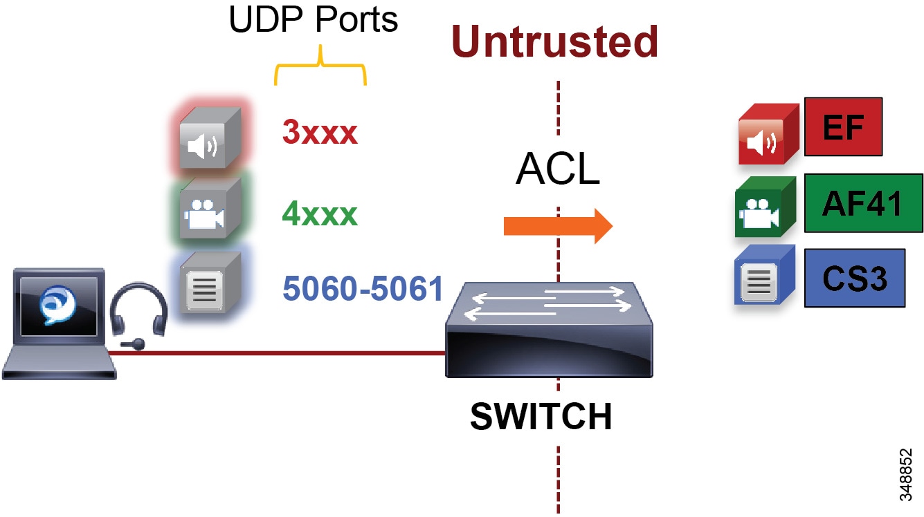
Figure 13-18 illustrates the following example ACL-based QoS policy for Jabber clients:
- UDP Port Range 3xxx Mark to DSCP EF
- UDP Port Range 4xxx Mark to DSCP AF41
- TCP Port 5060-5061 Mark to DSCP CS3

Note![]() The following example access control list is based on the Cisco Common Classification Policy Language (C3PL). Refer to your specific switch or router configuration guides to achieve the same policy on a Cisco device that does not support C3PL or for any updated commands in C3PL. This configuration is portable to all currently shipping switches including Modular QoS CLI-MQC, Multi-Layer Switching (MLS), and C3PL.
The following example access control list is based on the Cisco Common Classification Policy Language (C3PL). Refer to your specific switch or router configuration guides to achieve the same policy on a Cisco device that does not support C3PL or for any updated commands in C3PL. This configuration is portable to all currently shipping switches including Modular QoS CLI-MQC, Multi-Layer Switching (MLS), and C3PL.
QoS for Cisco Jabber Clients
As discussed, this method involves classifying media and signaling by identifying the various streams from the Jabber client based on IP address, protocol, and/or protocol port range. Once identified, the signaling and media streams can be classified and remarked with a corresponding DSCP. The protocol port ranges are configured in Unified CM and are passed to the endpoint to use during device registration. The network can then be configured via access control lists (ACLs) to classify traffic based on IP address, protocol, and protocol port range and then re-mark the classified traffic with the appropriate DSCP as discussed above.
Cisco Jabber provides identifiable media streams based on UDP protocol port ranges and identifiable signaling streams based on TCP protocol port ranges. In Unified CM, the signaling port for endpoints is configured in the SIP Security Profile, while the media port range is configured in the SIP Profile of the Cisco Unified CM administration pages.
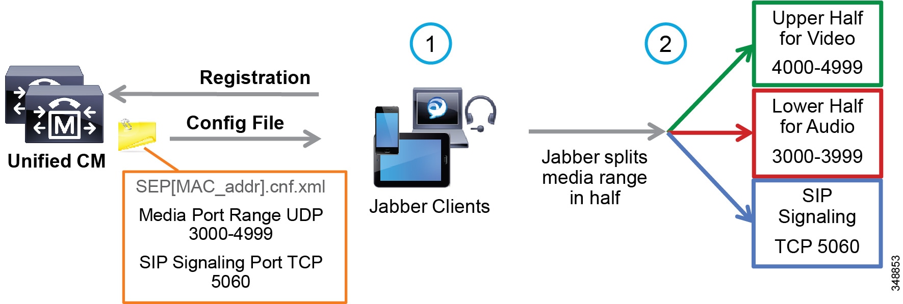
For the media port range, all endpoints and clients use the SIP profile parameter Media Port Range to derive the UDP ports used for media. By default media port ranges are configured with Common Port Range for Audio and Video. When Jabber clients receive this port range in their Config file, they split the port range in half and use the lower half for the audio streams of both voice and video calls and the upper half for the video streams of video calls. Jabber does not place the audio of a video call in the video UDP port range when using the Media Port Range > Common Port Range for Audio and Video configuration. This is illustrated in Figure 13-19.
Figure 13-19 Media and Signaling Port Range – Common
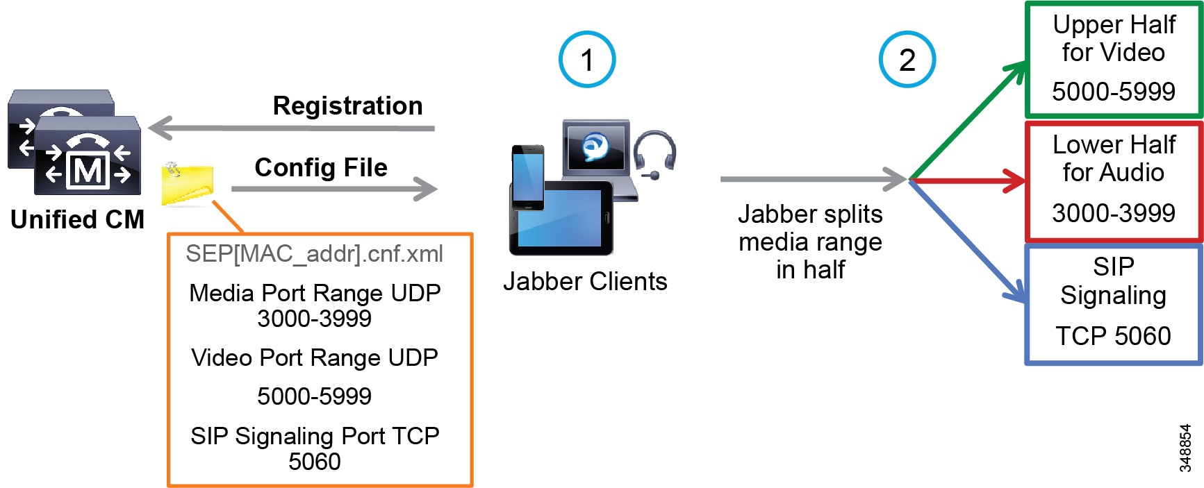
Jabber can also use the Media Port Range > Separate Port Range for Audio and Video configuration. In this configuration the Unified CM administrator can configure a non-contiguous audio and video port range as illustrated in Figure 13-20.
Figure 13-20 Media and Signaling Port Range – Separate
Due to the behavior of Jabber clients regarding UDP port range assignment, it is often not possible to map Enhanced Locations Call Admission Control (EL-CAC) bandwidth deductions correctly with QoS markings. CAC deducts bandwidth for audio-only calls out of the voice pool, while both audio and video bandwidth of a video call is deducted out of the video pool. To be consistent with the admission control logic, audio streams of voice-only calls would need to be marked as EF while both audio and video streams of video calls would need to be marked AF41. The differentiation of audio between audio of voice-only calls and audio of video calls is not possible when using Cisco Jabber clients and UDP port ranges to map identifiable media streams. As a result, this technique is effective to achieve QoS only. Therefore, we recommend over-provisioning the priority queue for EF traffic to account for the audio of video sessions from Jabber clients that will send audio as EF, or using an alternate DSCP. Some strategies are discussed in the Bandwidth Management Design Examples.

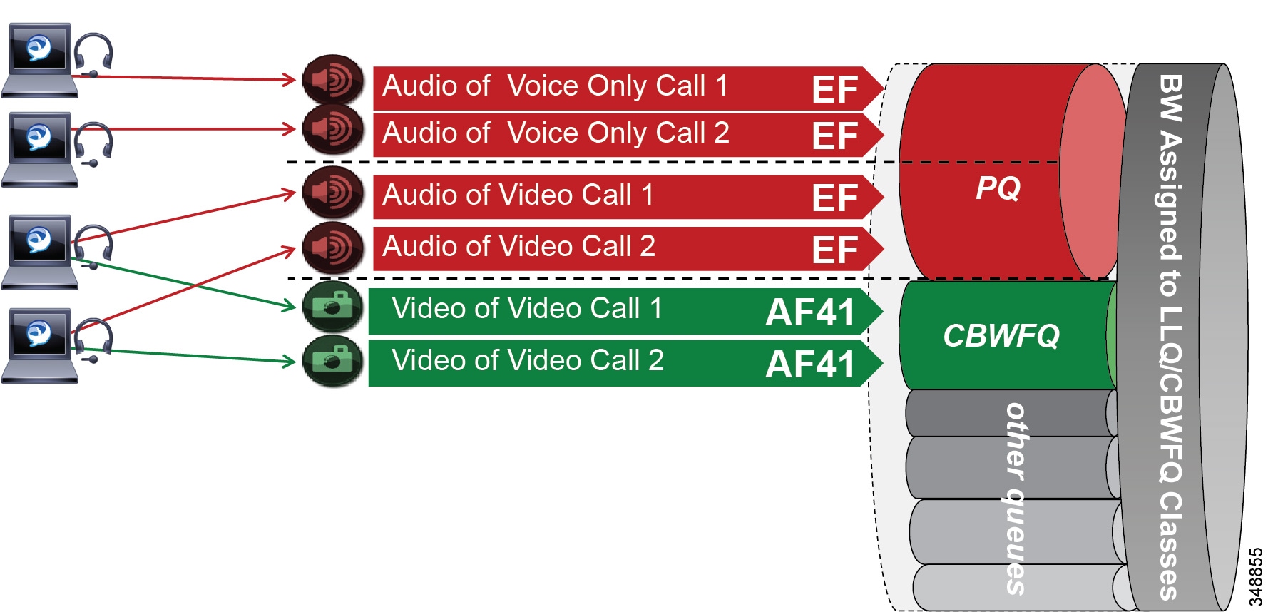
When utilizing this technique, it is important to ensure that the audio portion of these video calls that will be re-marked to the audio traffic class (EF) and the video portions re-marked to the video traffic class (AF4) are provisioned in the network accordingly. Figure 13-21 is an example of placing audio traffic into a Priority Queue (PQ) and video traffic into a Class Based Weighted Fair-Queue (CBWFQ). Note that, because it is not possible to differentiate the audio from voice-only calls versus the audio from video calls with port ranges in Cisco Jabber endpoints, all audio using this technique will be re-marked to EF. It is important to provision the PQ adequately to support voice-only and the audio portion of video calls. An example of such provisioning is illustrated in Figure 13-21. For more information on the design and deployment recommendations for provisioning queuing and scheduling in the network, see the section on WAN Queuing and Scheduling.
Figure 13-21 Provisioning Jabber QoS in the Network
According to RFC 3551, when RTCP is enabled on the endpoints, it uses the next higher odd port. For example, a device that establishes an RTP stream on port 3500 would send RTCP for that same stream on port 3501. This function of RTCP is also true with all Jabber clients. RTCP is common in most call flows and is commonly used for statistical information about the streams and to synchronize audio and video in video calls to ensure proper lip-sync. In most cases, video and RTCP can be enabled or disabled on the endpoint itself or in the common phone profile settings.
Utilizing the Network for Classification and Marking
Based on the identifiable media and signaling streams created by the Jabber client, common network QoS tools can be utilized to create traffic classes and re-mark packets according to these classes.
These QoS mechanisms can be applied at different layers, such as the access layer (access switch), which is closest to the endpoint and the router level in the distribution, core, or services WAN edge. Regardless of where classification and re-marking occur, we recommend using DSCP to ensure end-to-end per-hop behaviors.
As previously mentioned, Cisco Unified CM allows the port range utilized by SIP endpoints to be configured in the SIP profile. As a general rule, a port range of a minimum of 100 ports (for example, 3000 to 3099) is sufficient for most scenarios. A smaller range could be configured, as long as there are enough ports for the various audio, video, and associated RTCP ports (RTCP runs over the odd ports in the range).

Note![]() When deploying Jabber clients in networks where SCCP voice-only endpoints are deployed, the SCCP endpoints use a non-configurable hard-coded range of 16384 to 32767 for voice-only calls. Due to this, SCCP voice-only calls could run over the same range as SIP video-enabled endpoint calls if you do not change the media port range for SIP devices. If you are deploying a collaboration solution with endpoints that are configured to use SCCP, then we recommend setting the media port range of Jabber clients outside of the 16384 to 32767 range. The above examples of 3000 to 4999 for video-enabled Jabber clients and 3000 to 3999 for voice-only Jabber clients work very well to avoid overlap with SCCP endpoints.
When deploying Jabber clients in networks where SCCP voice-only endpoints are deployed, the SCCP endpoints use a non-configurable hard-coded range of 16384 to 32767 for voice-only calls. Due to this, SCCP voice-only calls could run over the same range as SIP video-enabled endpoint calls if you do not change the media port range for SIP devices. If you are deploying a collaboration solution with endpoints that are configured to use SCCP, then we recommend setting the media port range of Jabber clients outside of the 16384 to 32767 range. The above examples of 3000 to 4999 for video-enabled Jabber clients and 3000 to 3999 for voice-only Jabber clients work very well to avoid overlap with SCCP endpoints.
The recommendation to avoid overlap applies to other SIP-based video endpoints as well. To avoid overlap with SCCP-based audio endpoint ranges, the SIP-based video endpoints should also be allocated a port range that does not overlap with SCCP-based audio port range (16384 to 32767) or the Jabber clients’ media port range.
Access Layer (Layer 2 Definitions)
When using the access layer to classify traffic, the classification occurs at the ingress of traffic into the network, allowing the flows to be identified as they enter. In environments where QoS policies are applied not only in the WAN but also within the LAN, all upstream components can rely on traffic markings when processing. Classification at the ingress allows different methods to be utilized based on different types of endpoints. Physical endpoints such as IP phones can rely on mechanisms such as the Cisco Discovery Protocol (CDP) or Link Layer Discovery Protocol-Media Endpoint Discovery (LLDP-MED) to establish a trust relationship. Once the device is identified as trusted, QoS markings received from the device are trusted throughout the network.
Configuring QoS policies in the access layer of the network could result in a significant number of devices that require configuration, which can create additional operational overhead. The QoS policy configurations should be standardized across the various switches of the access layer through templates. You can use configuration deployment tools to relieve the burden of manual configuration.
Distribution, Core, and Services WAN Edge (Layer 3 Definitions)
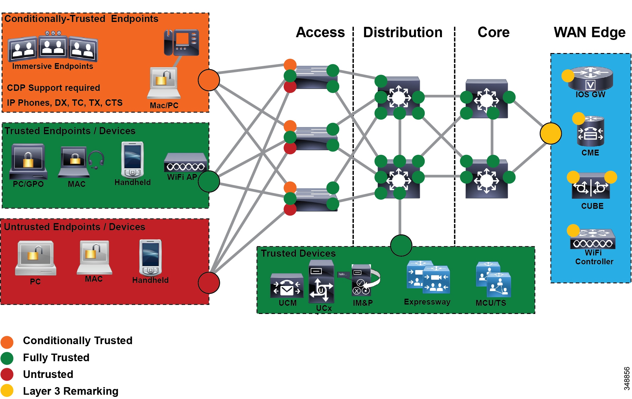
Another location where QoS marking can take place is at the Layer 3 routed boundary. In a campus network, Layer 3 could be in the access, distribution, core, or services WAN edge layer. The recommendation is to build the trust boundary and classify and re-mark at the access. Then trust through the distribution and core of the network, and finally re-classify and re-mark at the WAN edge. For smaller networks such as branch offices where there no Layer 3 switching components are deployed, QoS marking can be applied at the WAN edge router. At Layer 3, QoS policies are applied to the Layer 3 routing interfaces. In most campus networks these would be VLAN interfaces, but they could also be Fast Ethernet or Gigabit Ethernet interfaces. Figure 13-22 illustrates the areas of the network where the various types of trust are applied in relation to the places in the network – access, distribution, core, and WAN Edge.
Figure 13-22 Trust and Enforcement – Places in the Network
Utilizing the Operating System for QoS Trust, Classification, and Marking
Another method of QoS trust for Cisco Jabber clients is to allow the operating system on which the applications run to mark the QoS of the media and signaling at the request of the application. The benefit of this method is that it allows the network operators to extend the QoS trust model to the operating system itself, and then they can configure the network to "trust" the QoS markings and pass them through the network. It is not a common enterprise practice to extend QoS trust to the Windows PCs, Mac OS, and hand-held devices. The reason for this is that this method trusts all traffic from the device, not just traffic from authenticated application communication. These applications can be installed and used on these devices to "hijack" a priority QoS and defeat the original purpose of deploying QoS in the first place. Through administrative global policies, administrators can manage some operating systems such as Windows OS or user access controls to ensure that the OS does not accept unwanted applications or configurations. In these cases, it might be acceptable to use this method of QoS trust.
On Windows 7 and 8 operating systems it is necessary to configure specific policies, while in Mac OS, Apple iOS, and Android devices the OS natively marks at the request of the application without any specific configuration necessary.
The following sections discuss the Cisco Jabber clients and describe how each operating system functions with regard to application QoS classification and marking. Everything described in these sections relates to Layer 3 DSCP marking and not Layer 2 Class of Service (CoS):
Classification in Windows 7 and 8
Microsoft Windows 7 and Windows 8 take a different approach when it comes to QoS marking by the operating system because Microsoft's security enhancement, User Account Control (UAC), does not allow a regular application to set DSCP markings on IP packets, which is considered to be a security issue. The recommended option to allow for QoS/DSCP marking is by utilizing Microsoft Group Policies, called Group Policy Objects (GPOs), to allow certain applications to mark traffic based on protocol numbers and port ranges. As described earlier in this document, the identifiable traffic streams created by Cisco Jabber can be used in conjunction with GPOs to instruct the Windows operating system to mark traffic sent by a specific application (for example, CiscoJabber.exe). Like all GPOs, QoS GPOs can be configured only by an administrator, and therefore only the applications permitted by the GPOs are allowed to mark QoS via the operating system.
In most enterprises, the network administrators do not trust the QoS markings of devices that come from the data VLAN, such as PCs. Typically all traffic from the data VLANs is re-marked to a DSCP of 0 (best effort) on ingress into the access layer and then re-marked to DSCP based on other criteria such as UCP port ranges or protocol. Some enterprises with very strict OS policies and network access policies might trust the markings from operating systems over which they have full control. In this case, a QoS GPO can benefit by allowing Windows 7 or 8 operating systems to mark QoS traffic for specific applications such as a Cisco Jabber client.
For enterprises that deploy Cisco Jabber for Windows and that prefer to use GPOs to provide this level of QoS trust, this method may be an option.

GPOs are very similar to network access lists in how they allow the operating system to mark a specific application's QoS based on protocols, ports, and application executable. Figure 13-23 illustrates the process of QoS re-marking in Windows 7 and 8 with Jabber for Windows.
Figure 13-23 Group Policy Objects
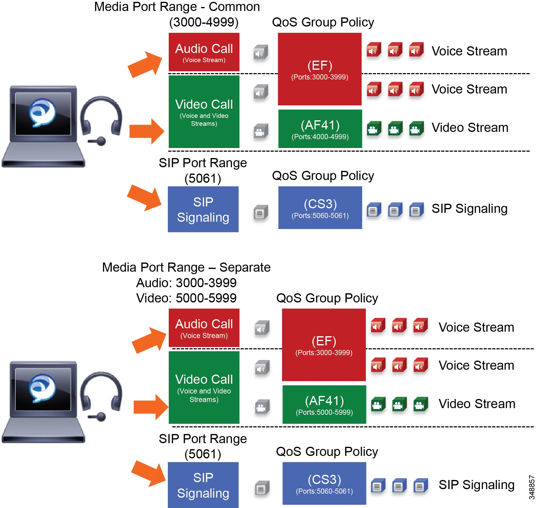
The process illustrated in Figure 13-23 starts with a QoS Group Policy that defines the IP address range (or any), the protocol (UDP), and port ranges (audio 3000 to 3999 and video 4000 to 4999). Once configured and applied to the OS, the Jabber for Windows client downloads its configuration from Unified CM on registration and applies the SIP Profile media port range - common. From there, when a Jabber for Windows client makes a call, it utilizes the media port ranges provided from Unified CM. The GPO applied to the Windows OS, however, applies its policy to take the media traffic for audio over UDP ports 3000 to 3999 and re-mark them to EF, and over UDP ports 4000 to 4999 and re-mark them to AF41. As the traffic leaves the OS, the packets will contain the applied markings. It will be up to the network to trust these markings and allow them to progress through the network. Figure 13-23 also illustrates a similar GPO when using non-contiguous port ranges in the SIP Profile for media port range - separated ports.
Classification in Mac OS
Cisco Jabber for Mac natively requests DSCP QoS marking to the operating system, which then marks traffic without the need to configure any specific policies.
Classification in Apple iOS (iPhone and iPad)
Cisco Jabber for iPad and iPhone natively requests DSCP QoS marking to the operating system, which then marks traffic without the need to configure any specific policies.
Classification in Android
Cisco Jabber for Android natively requests DSCP QoS marking to the operating system, which then marks traffic without the need to configure any specific policies.
Endpoint Identification and Classification Considerations and Recommendations
Design and deployment considerations and recommendations:
- Use DSCP markings whenever possible because they apply to the IP layer end-to-end and are more granular and more extensible than Layer 2 markings.
- Mark as close to the endpoint as possible, preferably at the LAN switch level.
- When deploying Jabber for voice and video in an environment where SCCP-based audio endpoints are deployed, change the media port range of the Cisco Jabber endpoints to use a range outside of 16384 to 32767 (which is a hard-coded range for SCCP devices). This is to avoid any potential overlap when creating network policies to re-mark DSCP based on the UDP port range. For example, use ports 3000 to 3999 for voice-only (video disabled) Jabber clients and 3000 to 4999 for video-enabled Cisco Jabber endpoints.
- When trying to minimize the number of media ports used by the Cisco Jabber client, use a minimum range of 100 ports. This is to ensure that there are enough ports for all of the streams, such as RTCP, RTP for audio and video, BFCP, and RTP for secondary video for desktop sharing sessions, as well as to avoid any overlap with other applications on the same computer.
- When deploying Enhanced Locations CAC, over-provision the audio class (EF) to account for the audio of video from Jabber clients that will be marked EF and not AF41.
Deploying QoS for Cisco Jabber clients can be achieved by mapping identifiable media and signaling streams with Layer 4 port ranges to Layer 3 DSCP values. Mapping identifiable media and signaling streams can be done for any Jabber client by using network access control lists (ACLs) or by using the operating system and then allowing the PC, Mac, or hand-held device’s QoS markings to pass through the network by trusting the QoS markings. Combining both methods is not advisable because the network ACL method will simply override the OS trust method and force the re-marking of all audio, thus rendering useless the goal of using the trust method.
WAN Queuing and Scheduling
Cisco's recommendations on QoS have evolved slightly over the past few years with regards to video. Historically two types of video have been classified: desktop video and immersive TelePresence video. As discussed in the section on Identification and Classification, Unified CM has the ability to differentiate the video endpoint types and the video streams from these endpoints. This provides the network administrator the ability to treat the video from these two types of endpoints differently. Historically the recommended DSCP markings have been AF41 for desktop video and CS4 for TelePresence video (immersive video). These values were in line with RFC 4594. Figure 13-24 illustrates a typical approach to classification and scheduling in the WAN. This identification and classification approach has been employed for a number of years but has some shortcomings when these two classes of traffic are applied to separate rate-based queues such as Class Based Weighted Fair Queues in Cisco IOS.

Note![]() This section discusses different Cisco IOS queuing and scheduling technologies that are covered in more detail in the section on WAN Quality of Service (QoS). This section discusses some of these technologies with the assumption that they are well understood technologies, and the discussion herein focuses on the best practices and recommendations for using these various Cisco IOS queuing and scheduling mechanisms.
This section discusses different Cisco IOS queuing and scheduling technologies that are covered in more detail in the section on WAN Quality of Service (QoS). This section discusses some of these technologies with the assumption that they are well understood technologies, and the discussion herein focuses on the best practices and recommendations for using these various Cisco IOS queuing and scheduling mechanisms.
Dual Video Queue Approach
In this approach to scheduling and queuing the traffic in the WAN, audio of a voice call is marked as EF and placed into a Priority Queue (PQ) with a strict policer on how much bandwidth the PQ can allocate to this traffic. Video calls are separated into two classes, an AF41 class for desktop type video and a CS4 class for TelePresence video (immersive). Each of these classes is put into a separate Class Based Weighted Fair Queue.
Figure 13-24 Dual Video Queue Approach
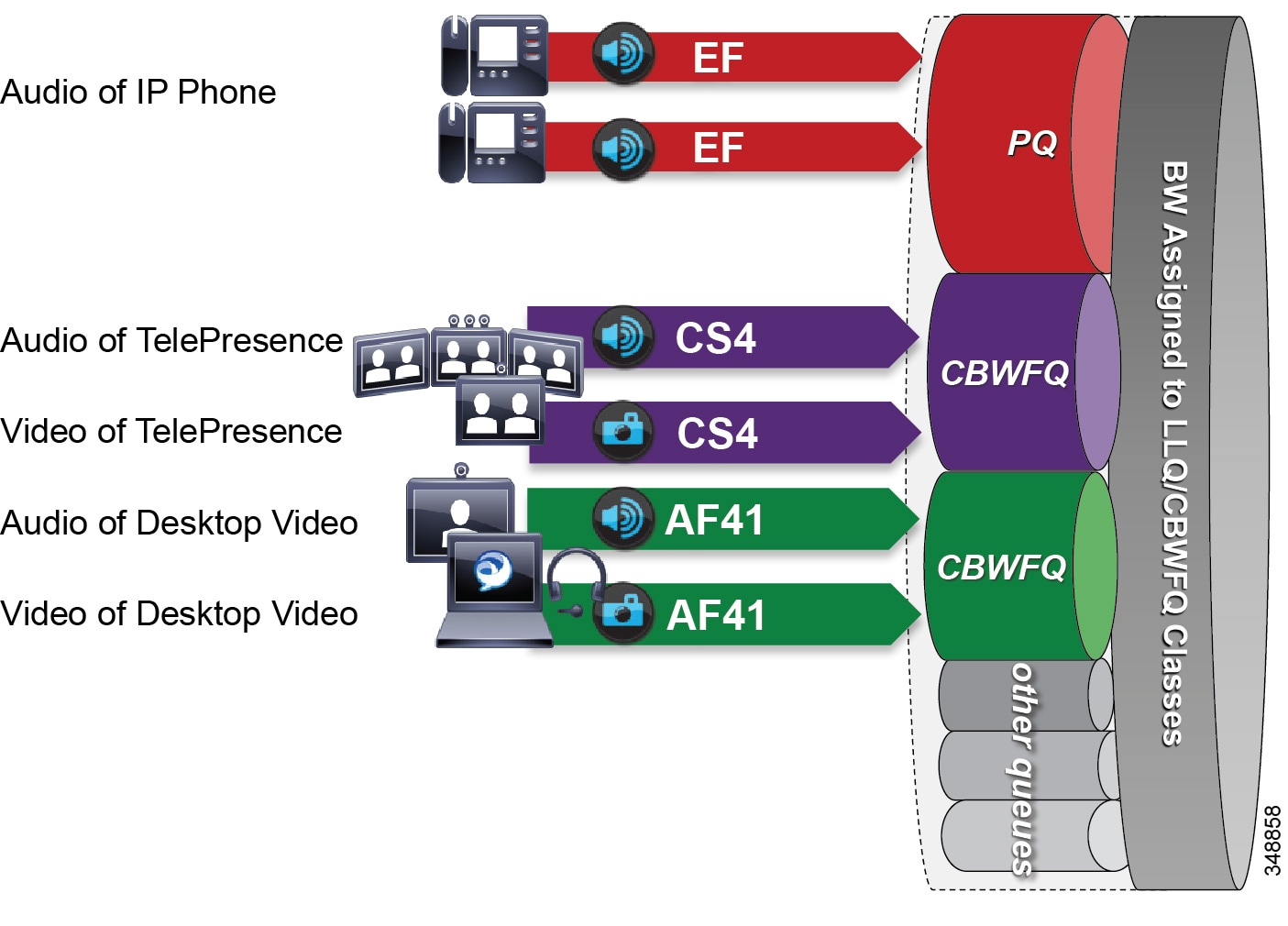
The dual video queue approach has the following shortcomings:
- Different queues for TelePresence (immersive) video and desktop video
- Complex provisioning — Requires managing multiple video queues and separating bandwidth allocations for each type of video rather than for video as a whole
- Sub-optimal bandwidth usage — When video for one class is not using all of its bandwidth, the remainder of the bandwidth becomes available to all of the other queues on the interface and not just the other video queue. Thus, it is not optimal for two different classes of video to share the total video bandwidth allocation effectively.
Other considerations of this approach with regard to the audio portion of a video call:
–![]() Same DSCP for audio and video streams of a video call
Same DSCP for audio and video streams of a video call
By default both audio and video of a video call are marked with the same DSCP value. As a result, both audio and video streams are equally impacted during congestion of the video queue. When video experiences packet loss, some video quality degradation can take place during the time that it takes for the video endpoints to rate adapt down to an acceptable level until packet loss is no longer experienced. Audio is a constant bit rate medium and does not have the same abilities for rate adaptation as video does. Thus, for audio this degradation can mean that the users are no longer able to communicate until the packet loss in the video queue is under control. Impacting audio has a greater effect on user experience than does impacting video. When video is impacted, users can still carry on a meeting or conversation while video is experiencing packet loss. See the section on Audio versus Video, for more information on the characteristics of both media.
–![]() Audio and video streams of a video call were traditionally marked with the same DSCP value in order to ensure that there was not a large delay variance between the two streams, otherwise video endpoints would not be able to sync audio and video correctly. With the implementation of RTCP in all Cisco endpoints, this is no longer a concern because RTCP can ensure the proper sync between audio and video of a video call. Of course, this requires RTCP to be enabled on the video endpoints.
Audio and video streams of a video call were traditionally marked with the same DSCP value in order to ensure that there was not a large delay variance between the two streams, otherwise video endpoints would not be able to sync audio and video correctly. With the implementation of RTCP in all Cisco endpoints, this is no longer a concern because RTCP can ensure the proper sync between audio and video of a video call. Of course, this requires RTCP to be enabled on the video endpoints.
- Audio stream classification for untrusted devices cannot be distinguished between voice-only calls and video calls.
–![]() Media stream identification is difficult for untrusted endpoints and clients. As discussed earlier, when the endpoint or client is not trusted, alternative methods for identification are required. With alternative methods such as access lists, it is difficult if not impossible in most cases to differentiate the audio of a voice-only call from the audio of a video call to classify those two types of audio differently. Therefore, all audio from both types of calls would have to be marked with a single DSCP value. This makes creating a holistic approach to uniform marking more difficult.
Media stream identification is difficult for untrusted endpoints and clients. As discussed earlier, when the endpoint or client is not trusted, alternative methods for identification are required. With alternative methods such as access lists, it is difficult if not impossible in most cases to differentiate the audio of a voice-only call from the audio of a video call to classify those two types of audio differently. Therefore, all audio from both types of calls would have to be marked with a single DSCP value. This makes creating a holistic approach to uniform marking more difficult.
Single Video Queue Approach
A newer recommendation for managing multiple types of video across an integrated collaboration media and data network is to use a single rate-based queue with multiple DSCPs with differing drop probabilities. In this new approach to scheduling video traffic in the WAN, the single video queue is configured with 2 or 3 AF4 drop probabilities using AF41, AF42, and AF43 – where AF43 has a higher drop precedence or probability than AF42, and AF42 has a higher drop precedence or probability than AF41. The premise behind a single video queue with this service class with hierarchical drop precedence is that, when one class of video is not using the bandwidth within the queue, the rest of the queue bandwidth is available for the other DSCP. This solves one of the major shortcoming of sub-optimal bandwidth utilization of the previous queuing approach with CS4 TelePresence video and AF41 desktop video in two separate rate-based queues.
Many different strategies for optimized video bandwidth utilization can be designed based on this single video queue with hierarchical DSCP drop probabilities. A simple example of this new QoS queuing approach can be illustrated by using the same two types of video, TelePresence video and desktop video, with two DSCP values of AF41 and AF42 in a single Class Based Weighted Fair Queue (CBWFQ). Figure 13-25 illustrates this approach.
Figure 13-25 Single Video Queue Approach
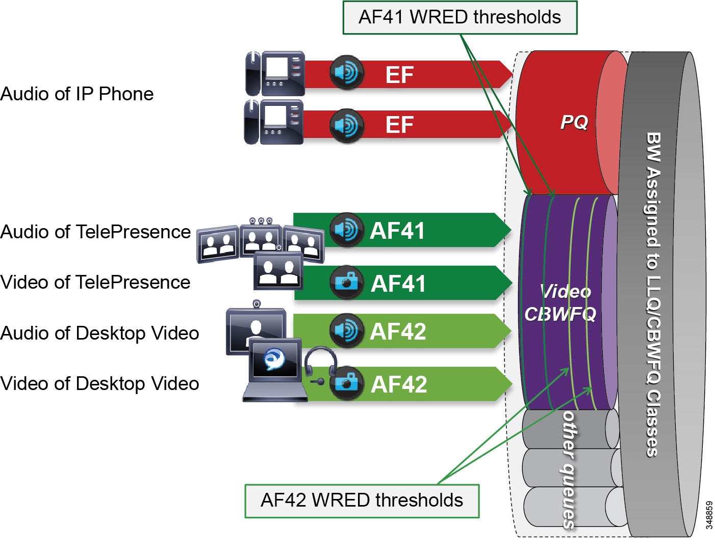
In Figure 13-25 the audio of a voice call is marked as EF and placed into a Priority Queue (PQ) with a strict policer on how much bandwidth the PQ can allocate to this traffic. Video calls are separated into two classes, AF41 for TelePresence video and AF42 for Desktop video. Using a CBWFQ with Weighted Random Early Detection (WRED), the administrator can adjust the drop precedence of AF42 over AF41, thus ensuring that during times of congestion when the queue is filling up, AF42 packets are dropped from the queue at a higher probability than AF41. See the section on WAN Quality of Service (QoS), for more detail on the function of WRED.
This example illustrates how an administrator using a single CBWFQ with DSCP-based WRED for all video can protect one type of video (TelePresence video) from packet loss over another type of video (Desktop) during periods of congestion. With this "single video queue approach," unlike the dual video queue approach, when one type of video is not using bandwidth in the queue, the other type of video gains full access to the entire queue bandwidth if and when needed. This is a significant point when looking to deploy pervasive video.
Considerations for Audio of Video Calls
The above single video queue example simply illustrates a point about how unused bandwidth from one class of video can be used fully by another class of video if both classes are in the same CBFWQ. This solves one of the shortcomings of the dual video queue approach. However, this does not address the other considerations for the audio portion of a video call, which as mentioned, has two main shortcomings:
- Audio of a video call can be impacted by packet loss in the video queue.
- Audio stream classification for untrusted devices cannot be distinguished between voice-only calls and video calls.
A strategy to address these deficiencies is to ensure that all audio is marked with a single value of Expedited Forwarding (EF) across the solution. In this way, whether the audio stream is associated to a voice-only call or a video call, it is always marked to the same single value. In this way, audio of a video call will be prioritized above the video and not subject to any packet loss in the video queue. It also solves the identification issue with untrusted devices such as Jabber clients. Because the marking of the client is not trusted by the network access layer, there is no effective way of distinguishing the audio stream of a voice-only call from the audio of a video call in the network. Thus, moving to this new model where all audio is marked with the same single value simplifies the network prioritization and treatment of the traffic.

Note![]() See the section on Trusted Endpoints, for information on how trusted endpoints acquire DSCP and how to set the DSCP for the audio portion of a video or TelePresence endpoint, and for information on which endpoints support this differentiation. Also, the section on Untrusted Endpoints and Clients, shows how to set DSCP for Jabber clients.
See the section on Trusted Endpoints, for information on how trusted endpoints acquire DSCP and how to set the DSCP for the audio portion of a video or TelePresence endpoint, and for information on which endpoints support this differentiation. Also, the section on Untrusted Endpoints and Clients, shows how to set DSCP for Jabber clients.
Achieving this holistically across the entire solution depends on a number of conditions that are required to achieve marking all audio to a DSCP of EF:
- The endpoint must support the DSCP for Audio Portion of Video/TelePresence Call QoS setting in Unified CM to be able to mark all audio as EF. See Table 13-8 for details on endpoint support.
- Jabber clients can support marking all audio as EF in a trusted or untrusted implementation.
- Enhanced Locations CAC can be implemented in conjunction with marking all audio as EF. ELCAC relies on the correct DSCP setting to ensure protection of the queues that voice and video CAC pools represent. Changing the DSCP of audio streams of the video calls requires updating how ELCAC deducts bandwidth for video calls. This can be done by setting the service parameter under the Call Admission Control section of the CallManager service, called Deduct Audio Bandwidth from Audio Pool for Video Call. This parameter can be set to true or false:
–![]() True : Cisco Unified CM splits the audio and video bandwidth allocations for video calls into separate pools. The bandwidth allocation for the audio portion of a video call is deducted from the audio pool, while the video portion of a video call is deducted from the video pool.
True : Cisco Unified CM splits the audio and video bandwidth allocations for video calls into separate pools. The bandwidth allocation for the audio portion of a video call is deducted from the audio pool, while the video portion of a video call is deducted from the video pool.
–![]() False : Cisco Unified CM applies the legacy behavior, which is to deduct the audio and video bandwidth allocations of a video call from the video pool. This is the default setting.
False : Cisco Unified CM applies the legacy behavior, which is to deduct the audio and video bandwidth allocations of a video call from the video pool. This is the default setting.
For more information on the admission control aspects of marking all audio of video to EF, see the ELCAC section on Deducting all Audio from the Voice Pool.
Opportunistic Video
When attempting to deploy video pervasively across the organization, bandwidth constraints typically determine the level of video resolution can be achieved during the busiest hour of the day based on the bandwidth available and the number of video calls during that busy hour. To address this challenge, a type of video can be targeted as opportunistic video using a single video queue with DSCP-based WRED coupled with a strategy for identification and classification of collaboration media.
Opportunistic video means achieving the best video quality based on the WAN bandwidth resources available at any given time. To achieve this, a number of requirements must be met:
- Selecting a group of video endpoints to be opportunistic
- Ensuring the WAN is configured with a single video queue using DSCP-based WRED with AF4 DSCP class servicing with drop precedence of AF41, AF42, and AF43 (only two DSCPs are required)
- Identifying and classifying the video of opportunistic endpoints with AF42
- Identifying and classifying all other video endpoints with AF41
Provisioning and Admission Control
Provisioning bandwidth and ensuring the correct bit rate is negotiated between various groups of endpoints, are important aspects of bandwidth management. In a Unified CM environment, bit rate is negotiated via Unified CM, which uses a concept of regions to set the maximum audio and maximum video bit rates for any given call flow. This section focuses on the maximum bit rate for video and TelePresence.
Unified CM Regions
Unified CM locations (see Enhanced Locations Call Admission Control) work in conjunction with regions to define the characteristics of a call flow. Regions define the type of compression or bit rate (8 kbps or G.729, 64 kbps or G.722/G.711, and so forth) that is used between any two devices. Location links define the amount of available bandwidth for the path between devices. Each device and trunk in the system is assigned to both a region (by means of a device pool) and a location (by means of a device pool or by direct configuration on the device itself):
- Regions allow the bandwidth of video calls to be set. The audio limit on the region can result in filtering out codecs with higher bit rates. However, for video calls, the video limit constrains the quality (resolution and transmission rate) of the video.
- Locations define the amount of total bandwidth available for all calls on that link. When a call is made on a link, the regional value for that call must be subtracted from the total bandwidth allowed for that link.
Building a region matrix to manage maximum video bit rate (video resolution) for groups of devices can assist in ensuring that certain groups of devices do not over-saturate the network bandwidth. Some guidelines for creating a region matrix include:
- Group devices into maximum video bit rate categories.
- The smaller the number of groups, the easier it is to calculate bandwidth requirements.
- Consider the default region settings to simplify the matrix and provide intra-region and inter-region defaults.
For more about region settings, see the section on Enhanced Locations Call Admission Control.
Table 13-9 shows an example of a maximum video bit rate region matrix for four groups of devices.

Note![]() Table 13-9 is only an example of how to group devices and what maximum bit rate might be suggested for a general resolution between the groups of devices.
Table 13-9 is only an example of how to group devices and what maximum bit rate might be suggested for a general resolution between the groups of devices.
|
|
|
|
|
|
|---|---|---|---|---|
|
|
||||
|
|
||||
|
|
||||
|
|
In Table 13-9 the four groups are:
- Legacy (Small Screen) — These could be legacy endpoints with smaller low-resolution screens or other devices to be capped at 800 kbps bit rate.
- Jabber — These would typically make up the largest group of deployed video-capable endpoints and thus benefit from the opportunistic video approach. When classified as opportunistic video, they can go up to a maximum of 1,500 kbps (720p@30fps) and would rate adapt downward based on packet loss.
- Room System + Smart Desktop — These would be room systems such as Cisco MX, SX, C, or Profile Series. Also, smart desktop endpoints would be Cisco DX and EX Series. At 2,500 kbps maximum video bit rate, these endpoints would typically be capable of 720p@30fps
- Immersive + MCU — These would be the larger Cisco TX or IX Series endpoints as well as MCUs set to a maximum of 12 Mbps, which roughly translates to 1080p@30fps with other TelePresence devices and MCUs.
Other region considerations for bandwidth provisioning:
- The first consideration is whether to have different intra-region settings versus inter-region settings. This will determine whether per-site regions are required or not. The concept here is that if intra- and inter-regional audio or video bit rates are to be different, then per-site regions will be required. This augments the configuration of regions to the number of sites (N) multiplied by the number of video groups (X): N∗X = number of regions required on average. If intra- and inter-region audio and video bit rates will be the same, then only the regions for the video groups are required (X).
- Reuse regions configured for audio-only IP phones when possible.
–![]() Audio codec configuration is shared, so if video calls need to use different audio codecs, you need to configure new regions. For example, if voice-only devices use the G.729 audio codec over the WAN and G.711 or G.722 on the LAN, while video devices always use G7.11 or G.722, then the voice-only and video endpoints cannot share a region. Thus, each site would require a region per group of devices. Sites = N, and video region groups = 4 + voice-only region group; then N*4 is the number of regions required. Use the Prime Collaboration Provisioning tool or the Bulk Administration tool as configuration aids.
Audio codec configuration is shared, so if video calls need to use different audio codecs, you need to configure new regions. For example, if voice-only devices use the G.729 audio codec over the WAN and G.711 or G.722 on the LAN, while video devices always use G7.11 or G.722, then the voice-only and video endpoints cannot share a region. Thus, each site would require a region per group of devices. Sites = N, and video region groups = 4 + voice-only region group; then N*4 is the number of regions required. Use the Prime Collaboration Provisioning tool or the Bulk Administration tool as configuration aids.
–![]() Per-site regions might not be needed if a single audio codec is used for both intra-region and inter-region calls as well as voice-only calls. If both audio and video endpoints use G.711 or G.722 over the WAN and LAN for voice-only or video calls, then voice-only IP phones and video endpoints could use the same region.
Per-site regions might not be needed if a single audio codec is used for both intra-region and inter-region calls as well as voice-only calls. If both audio and video endpoints use G.711 or G.722 over the WAN and LAN for voice-only or video calls, then voice-only IP phones and video endpoints could use the same region.
- Consider the default region settings to simplify the matrix. The following example illustrates possible default settings based on the region groupings in Figure 13-25. If it is desired to have the intra-region bit rate be larger than the inter-region bit rate, then per-site regions are required.
–![]() Default Intraregion Max Video Call Bit Rate (Includes Audio): Set to 768, sets the maximum video bit rate capability of devices for calls within a region to 768 kbps.
Default Intraregion Max Video Call Bit Rate (Includes Audio): Set to 768, sets the maximum video bit rate capability of devices for calls within a region to 768 kbps.
–![]() Default Interregion Max Video Call Bit Rate (Includes Audio): Set to 768, sets the maximum video bit rate capability of devices for calls between regions to 768 kbps.
Default Interregion Max Video Call Bit Rate (Includes Audio): Set to 768, sets the maximum video bit rate capability of devices for calls between regions to 768 kbps.
–![]() Default Intraregion Max Immersive Video Call Bit Rate (Includes Audio): Set to 12000, sets the maximum video bit rate capability of devices for calls within a region to 12,000 kbps.
Default Intraregion Max Immersive Video Call Bit Rate (Includes Audio): Set to 12000, sets the maximum video bit rate capability of devices for calls within a region to 12,000 kbps.
–![]() Default Interregion Max Immersive Video Call Bit Rate (Includes Audio): Set to 12000, sets the maximum video bit rate capability of devices for calls between regions to 12,000 kbps.
Default Interregion Max Immersive Video Call Bit Rate (Includes Audio): Set to 12000, sets the maximum video bit rate capability of devices for calls between regions to 12,000 kbps.
–![]() In addition to the defaults, 4 regions should be set up, one for each group of video endpoints.
In addition to the defaults, 4 regions should be set up, one for each group of video endpoints.
Enhanced Locations Call Admission Control
The call admission control function can be an important component of a Collaboration system, especially when multiple sites are connected through an IP WAN and limited bandwidth resources are available for audio and video calls. To better understand what call admission control does and why it is needed, consider the example in Figure 13-26.
Figure 13-26 Why Call Admission Control is Needed
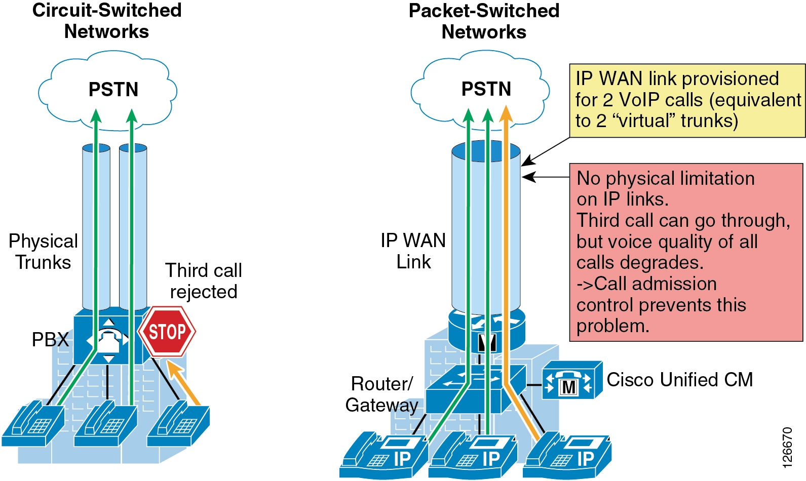
As shown on the left side of Figure 13-26, traditional TDM-based PBXs operate within circuit-switched networks, where a circuit is established each time a call is set up. As a consequence, when a legacy PBX is connected to the PSTN or to another PBX, a certain number of physical trunks must be provisioned. When calls have to be set up to the PSTN or to another PBX, the PBX selects a trunk from those that are available. If no trunks are available, the call is rejected by the PBX and the caller hears a network-busy signal.
Now consider the IP connected Unified Communications system shown on the right side of Figure 13-26. Because it is based on a packet-switched network (the IP network), no circuits are established to set up an IP telephony call. Instead, the IP packets containing the voice samples are simply routed across the IP network together with other types of data packets. Quality of Service (QoS) is used to differentiate the voice packets from the data packets, but bandwidth resources, especially on IP WAN links, are not infinite. Therefore, network administrators dedicate a certain amount of "priority" bandwidth to voice traffic on each IP WAN link. However, once the provisioned bandwidth has been fully utilized, the IP telephony system must reject subsequent calls to avoid oversubscription of the priority queue on the IP WAN link, which would cause quality degradation for all voice calls. This function is known as call admission control, and it is essential to guarantee good voice and video quality in a multisite deployment involving an IP WAN.
To preserve a satisfactory end-user experience, the call admission control function should always be performed during the call setup phase so that, if network resources are not available, a message can be presented to the end-user or the call can be rerouted across a different network (such as the PSTN).
This chapter discusses the following main topics:
This section describes the call admission control mechanism available through Cisco Unified Communications Manager called Enhanced Location Call Admission Control. For information regarding Cisco IOS gatekeeper, RSVP, and RSVP SIP Preconditions, refer to the Call Admission Control chapter of the Cisco Unified Communications System 9.0 SRND, available at
http://www.cisco.com/en/US/docs/voice_ip_comm/cucm/srnd/9x/cac.html
This section shows how to apply Enhanced Location Call Admission Control based on the IP WAN topology.
Call Admission Control Architecture
This section provides design and configuration guidelines for Enhanced Location Call Admission Control based on Cisco Unified CM.
Unified CM Enhanced Location Call Admission Control
Cisco Unified CM provides Enhanced Location Call Admission Control (ELCAC) to support complex WAN topologies as well as distributed deployments of Unified CM for call admission control where multiple clusters manage devices in the same physical sites using the same WAN uplinks. The Enhanced Location CAC feature also supports immersive video, allowing the administrator to control call admissions for immersive video calls such as TelePresence separately from other video calls.
To support more complex WAN topologies Unified CM has implemented a location-based network modeling functionality. This provides Unified CM with the ability to support multi-hop WAN connections between calling and called parties. This network modeling functionality has also been incrementally enhanced to support multi-cluster distributed Unified CM deployments. This allows the administrator to effectively "share" locations between clusters by enabling the clusters to communicate with one another to reserve, release, and adjust allocated bandwidth for the same locations across clusters. In addition, an administrator has the ability to provision bandwidth separately for immersive video calls such as TelePresence by allocating a new field to the Location configuration called immersive video bandwidth.
There are also tools to administer and troubleshoot Enhanced Location CAC. The CAC enhancements and design are discussed in detail in this chapter, but the troubleshooting and serviceability tools are discussed in separate product documentation.
Network Modeling with Locations, Links, and Weights
Enhanced Location CAC is a model-based static CAC mechanism. Enhanced Location CAC involves using the administration interface in Unified CM to configure Locations and Links to model the "Routed WAN Network" in an attempt to represent how the WAN network topology routes media between groups of endpoints for end-to-end audio, video, and immersive calls. Although Unified CM provides configuration and serviceability interfaces in order to model the network, it is still a "static" CAC mechanism that does not take into account network failures and network protocol rerouting. Therefore, the model needs to be updated when the WAN network topology changes. Enhanced Location CAC is also call oriented, and bandwidth deductions are per-call not per-stream, so asymmetric media flows where the bit-rate is higher in one direction than in the other will always deduct for the highest bit rate. In addition, unidirectional media flows will be deducted as if they were bidirectional media flows.
Enhanced Location CAC incorporates the following configuration components to allow the administrator to build the network model using Locations and Links:
- Locations — A Location represents a LAN. It could contain endpoints or simply serve as a transit location between links for WAN network modeling. For example, an MPLS provider could be represented by a Location.
- Links — Links interconnect locations and are used to define bandwidth available between locations. Links logically represent the WAN link and are configured in the Location user interface (UI).
- Weights — A weight provides the relative priority of a link in forming the effective path between any pair of locations. The effective path is the path used by Unified CM for the bandwidth calculations, and it has the least cumulative weight of all possible paths. Weights are used on links to provide a "cost" for the "effective path" and are pertinent only when there is more than one path between any two locations.
- Path — A path is a sequence of links and intermediate locations connecting a pair of locations. Unified CM calculates least-cost paths (lowest cumulative weight) from each location to all other locations and builds a map of the various paths. Only one "effective path" is used between any pair of locations.
- Effective Path — The effective path is the path with the least cumulative weight.
- Bandwidth Allocation — The amount of bandwidth allocated in the model for each type of traffic: audio, video, and immersive video (TelePresence).
- Location Bandwidth Manager (LBM) — The active service in Unified CM that assembles a network model from configured location and link data in one or more clusters, determines the effective paths between pairs of locations, determines whether to admit calls between a pair of locations based on the availability of bandwidth for each type of call, and deducts (reserves) bandwidth for the duration of each call that is admitted.
- Location Bandwidth Manager Hub — A Location Bandwidth Manager (LBM) service that has been designated to participate directly in intercluster replication of fixed locations, links data, and dynamic bandwidth allocation data. LBMs assigned to an LBM hub group discover each other through their common connections and form a fully-meshed intercluster replication network. Other LBM services in a cluster with an LBM hub participate indirectly in intercluster replication through the LBM hubs in their cluster.
Locations and Links
Unified CM uses the concept of locations to represent a physical site and to create an association with media devices such as endpoints, voice messaging ports, trunks, gateways, and so forth, through direct configuration on the device itself, through a device pool, or even through device mobility. Unified CM also uses a new location configuration parameter called links. Links interconnect locations and are used to define bandwidth available between locations. Links logically represent the WAN links. This section describes locations and links and how they are used.
The location configuration itself consists of three main parts: links, intra-location bandwidth parameters, and RSVP locations settings. The RSVP locations settings are not considered here for Enhanced Location CAC because they apply only to RSVP implementations. In the configuration, the link bandwidth parameters are displayed first while the intra-location bandwidth parameters are hidden and displayed by selecting the Show advanced link.
The intra-location bandwidth parameters allow the administrator to configure bandwidth allocations for three call types: audio, video, and immersive. They limit the amount of traffic within, as well as to or from, any given location. When any device makes or receives a call, bandwidth is deducted from the applicable bandwidth allocation for that call type. This feature allows administrators to limit the amount of bandwidth used on the LAN or transit location. In most networks today that consist of Gigabit LANs, there is little or no reason to limit bandwidth on those LANs.
The link bandwidth parameters allow the administrator to characterize the provisioned bandwidth for audio, video, and immersive calls between "adjacent locations" (that is, locations that have a link configured between them). This feature offers the administrator the ability to create a string of location pairings in order to model a multi-hop WAN network. To illustrate this, consider a simple three-hop WAN topology connecting four physical sites, as shown in Figure 13-27. In this topology we want to create links between San Jose and Boulder, between Boulder and Richardson, and between Richardson and RTP. Note that when we create a link from San Jose to Boulder, for example, the inverse link (Boulder to San Jose) also exists. Therefore, the administrator needs to create the link pairing only once from either location configuration page. In the example in Figure 13-27, each of the three links has the same settings: a weight of 50, 240 kbps of audio bandwidth, 500 kbps of video bandwidth, and 5000 kbps (or 5 Mbps) of immersive bandwidth.
Figure 13-27 Simple Link Example with Three WAN Hops
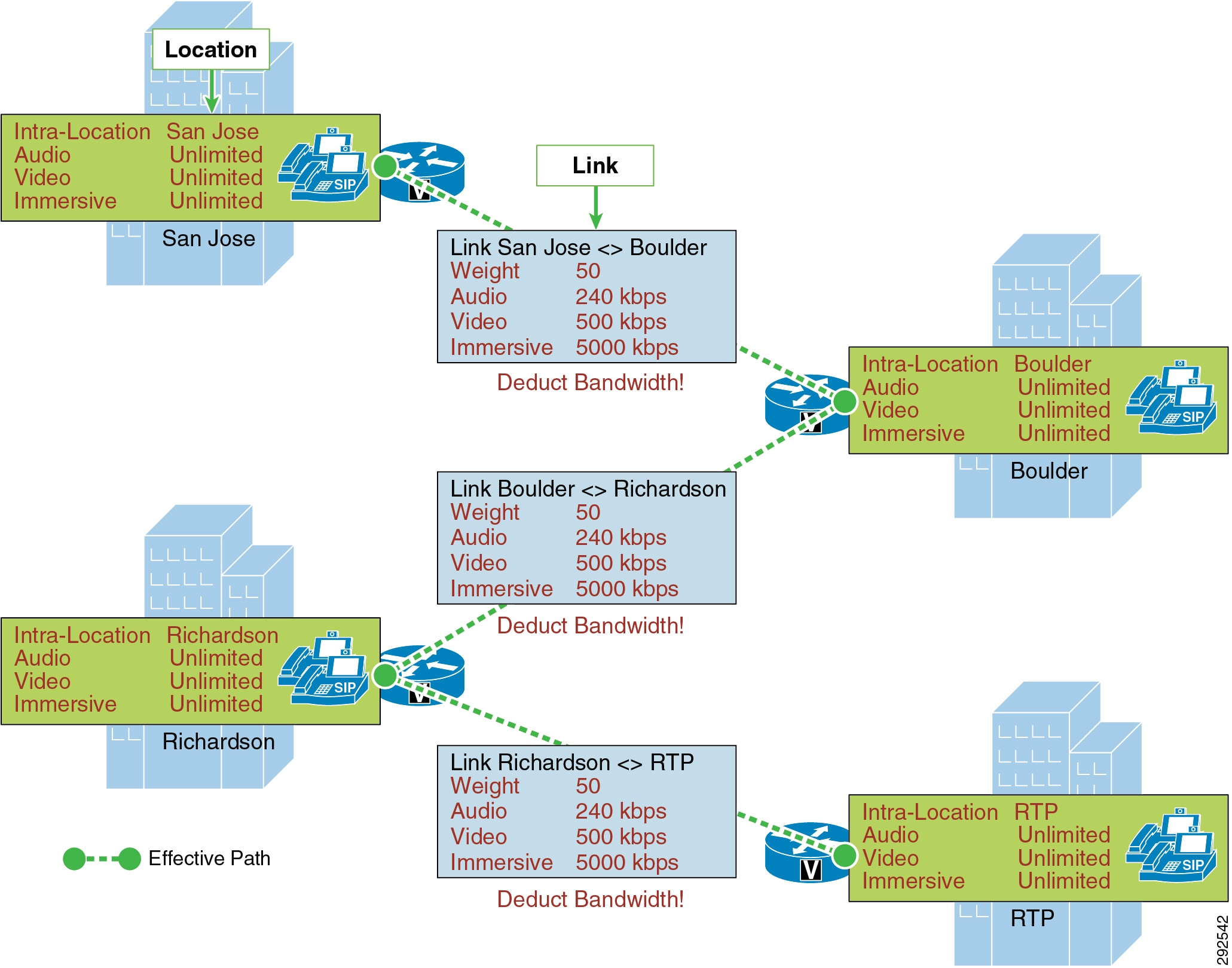
When a call is made between San Jose and RTP, Unified CM calculates the bandwidth of the requested call, which is determined by the region pair between the two devices (see Locations, Links, and Region Settings) and verifies the effective path between the two locations. That is to say, Unified CM verifies the locations and links that make up the path between the two locations and accordingly deducts bandwidth from each link and (if applicable) from each location in the path. The intra-location bandwidth also is deducted along the path if any of the locations has configured a bandwidth value other than unlimited.
Weight is configurable on the link only and provides the ability to force a specific path choice when multiple paths between two locations are available. When multiple paths are configured, only one will be selected based on the cumulative weight, and this path is referred to as the effective path. This weight is static and the effective path does not change dynamically. Figure 13-28 illustrates weight configured on links between three locations: San Jose, Boulder, and Seattle.
Figure 13-28 Cumulative Path Weights
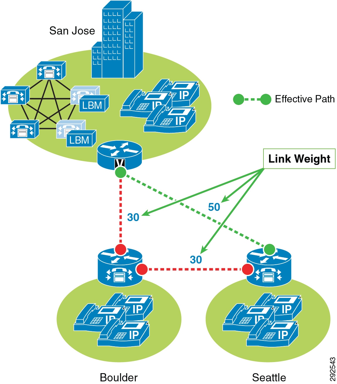
San Jose to Seattle has two paths, one direct link between the locations and another path through the Boulder location (link San Jose/Boulder and link Boulder/Seattle). The weight configured on the direct link between San Jose and Seattle is 50 and is less than the cumulative weight of links San Jose/Boulder and Boulder/Seattle which is 60 (30+30). Thus, the direct link is chosen as the effective path because the cumulative link weight is 50.
When you configure a device in Unified CM, the device can be assigned to a location. A location can be configured with links to other locations in order to build a topology. The locations configured in Unified CM are virtual locations and not real, physical locations. As mentioned, Unified CM has no knowledge of the actual physical topology of the network. Therefore, any changes to the physical network must be made manually in Unified CM to map the real underlying network topology with the Unified CM locations model. If a device is moved from one physical location to another, the system administrator must either perform a manual update on its location configuration or else implement the device mobility feature so that Unified CM can correctly calculate bandwidth allocations for calls to and from that device. Each device is in location Hub_None by default. Location Hub_None is an example location that typically serves as a hub linking two or more locations, and it is configured by default with unlimited intra-location bandwidth allocations for audio, video, and immersive bandwidth.
Unified CM allows you to define separate voice, video, and immersive video bandwidth pools for each location and link between locations. Typically the locations intra-location bandwidth configuration is left as a default of Unlimited while the link between locations is set to a finite number of kilobits per second (kbps) to match the capacity of a WAN links between physical sites. If the location's intra-location audio, video, and immersive bandwidths are configured as Unlimited, there will be unlimited bandwidth available for all calls (audio, video, and immersive) within that location and transiting that location. On the other hand, if the bandwidth values are set to a finite number of kilobits per second (kbps), Unified CM will track all calls within the location and all calls that use the location as a transit location (a location that is in the calculation path but is not the originating or terminating location in the path).
For video calls, the video location bandwidth takes into account both the audio and the video portions of the video call. Therefore, for a video call, no bandwidth is deducted from the audio bandwidth pool. The same applies to immersive video calls.
The devices that can specify membership in a location include:
- IP phones
- CTI ports
- H.323 clients
- CTI route points
- Conference bridges
- Music on hold (MoH) servers
- Gateways
- Trunks
- Media termination point (via device pool)
- Trusted relay point (via device pool)
- Annunciator (via device pool)
The Enhanced Location Call Admission Control mechanism also takes into account the mid-call changes in call type. For example, if an inter-site video call is established, Unified CM will subtract the appropriate amount of video bandwidth from the respective locations and links in the path. If this video call changes to an audio-only call as the result of a transfer to a device that is not capable of video, Unified CM will return the allocated bandwidth to the video pool and allocate the appropriate amount of bandwidth from the audio pool along the same path. Calls that change from audio to video will cause the opposite change of bandwidth allocation.
Table 13-10 lists the amount of bandwidth requested by the static locations algorithm for various call speeds. For an audio call, Unified CM counts the media bit rates plus the IP and UDP overhead. For example, a G.711 audio call consumes 80 kbps (64k bit rate + 16k IP/UDP headers) deducted from the location's and link's audio bandwidth allocation. For a video call, Unified CM counts only the media bit rates for both the audio and video streams. For example, for a video call at a bit rate of 384 kbps, Unified CM will allocate 384 kbps from the video bandwidth allocation.
|
|
|
|---|---|
For a complete list of codecs and location and link bandwidth values, refer to the bandwidth calculations information in the Call Admission Control section of the Cisco Unified Communications Manager System Guide, available at
http://www.cisco.com/en/US/products/sw/voicesw/ps556/prod_maintenance_guides_list.html
For example, assume that the link configuration for the location Branch 1 to Hub_None allocates 256 kbps of available audio bandwidth and 384 kbps of available video bandwidth. In this case the path from Branch 1 to Hub_None can support up to three G.711 audio calls (at 80 kbps per call) or ten G.729 audio calls (at 24 kbps per call), or any combination of both that does not exceed 256 kbps. The link between locations can also support different numbers of video calls depending on the video and audio codecs being used (for example, one video call requesting 384 kbps of bandwidth or three video calls with each requesting 128 kbps of bandwidth).
When a call is placed from one location to the other, Unified CM deducts the appropriate amount of bandwidth from the effective path of locations and links from one location to another. Using Figure 13-27 as an example, a G.729 call between San Jose and RTP locations causes Unified CM to deduct 24 kbps from the available bandwidth at the links between San Jose and Boulder, between Boulder and Richardson, and between Richardson and RTP. When the call has completed, Unified CM returns the bandwidth to those same links over the effective path. If there is not enough bandwidth at any one of the links over the path, the call is denied by Unified CM and the caller receives the network busy tone. If the calling device is an IP phone with a display, that device also displays the message "Not Enough Bandwidth."
When an inter-location call is denied by call admission control, Unified CM can automatically reroute the call to the destination through the PSTN connection by means of the Automated Alternate Routing (AAR) feature. For detailed information on the AAR feature, see Automated Alternate Routing.

Note![]() AAR is invoked only when Enhanced Location Call Admission Control denies the call due to a lack of network bandwidth along the effective path. AAR is not invoked when the IP WAN is unavailable or other connectivity issues cause the called device to become unregistered with Unified CM. In such cases, the calls are redirected to the target specified in the Call Forward No Answer field of the called device.
AAR is invoked only when Enhanced Location Call Admission Control denies the call due to a lack of network bandwidth along the effective path. AAR is not invoked when the IP WAN is unavailable or other connectivity issues cause the called device to become unregistered with Unified CM. In such cases, the calls are redirected to the target specified in the Call Forward No Answer field of the called device.
It is also worth noting that video devices can be enabled to Retry Video Call as Audio if a video call between devices fails CAC. This option is configured on the video endpoint configuration page in Unified CM and is applicable to video endpoints or trunks receiving calls. It should also be noted that for some video endpoints Retry Video Call as Audio is enabled by default and not configurable on the endpoint.
Locations, Links, and Region Settings
Locations work in conjunction with regions to define the characteristics of a call over the effective path of locations and links. Regions define the type of compression or bit rate (8 kbps or G.729, 64 kbps or G.722/G.711, and so forth) that is used between devices, and location links define the amount of available bandwidth for the effective path between devices. You assign each device in the system to both a region (by means of a device pool) and a location (by means of a device pool or by direct configuration on the device itself).
You can configure locations in Unified CM to define:
- Physical sites (for example, a branch office) or transit sites (for example, an MPLS cloud) — A location represents a LAN. It could contain endpoints or simply serve as a transit location between links for WAN network modeling.
- Link bandwidth between adjacent locations — Links interconnect locations and are used to define bandwidth available between locations. Links logically represent the WAN link between physical sites.
–![]() Audio Bandwidth — The amount of bandwidth that is available in the WAN link for voice and fax calls being made from devices in the location to the configured adjacent location. Unified CM uses this bandwidth value for Enhanced Location Call Admission Control.
Audio Bandwidth — The amount of bandwidth that is available in the WAN link for voice and fax calls being made from devices in the location to the configured adjacent location. Unified CM uses this bandwidth value for Enhanced Location Call Admission Control.
–![]() Video Bandwidth — The amount of video bandwidth that is available in the WAN link for video calls being made from devices in the location to the configured adjacent location. Unified CM uses this bandwidth value for Enhanced Location Call Admission Control.
Video Bandwidth — The amount of video bandwidth that is available in the WAN link for video calls being made from devices in the location to the configured adjacent location. Unified CM uses this bandwidth value for Enhanced Location Call Admission Control.
–![]() Immersive Video Bandwidth — The amount of immersive bandwidth that is available in the WAN link for TelePresence calls being made from devices in the location to the configured adjacent location. Unified CM uses this bandwidth value for Enhanced Location Call Admission Control.
Immersive Video Bandwidth — The amount of immersive bandwidth that is available in the WAN link for TelePresence calls being made from devices in the location to the configured adjacent location. Unified CM uses this bandwidth value for Enhanced Location Call Admission Control.
–![]() Audio Bandwidth — The amount of bandwidth that is available in the LAN for voice and fax calls being made from devices within the location. Unified CM uses this bandwidth value for Enhanced Location Call Admission Control.
Audio Bandwidth — The amount of bandwidth that is available in the LAN for voice and fax calls being made from devices within the location. Unified CM uses this bandwidth value for Enhanced Location Call Admission Control.
–![]() Video Bandwidth — The amount of video bandwidth that is available in the LAN for video calls being made from devices within the location. Unified CM uses this bandwidth value for Enhanced Location Call Admission Control.
Video Bandwidth — The amount of video bandwidth that is available in the LAN for video calls being made from devices within the location. Unified CM uses this bandwidth value for Enhanced Location Call Admission Control.
–![]() Immersive Video Bandwidth — The amount of immersive bandwidth that is available in the LAN for TelePresence calls being made from devices within the location. Unified CM uses this bandwidth value for Enhanced Location Call Admission Control.
Immersive Video Bandwidth — The amount of immersive bandwidth that is available in the LAN for TelePresence calls being made from devices within the location. Unified CM uses this bandwidth value for Enhanced Location Call Admission Control.
You can configure regions in Unified CM to define:
- The Maximum Audio Bit Rate used for intraregion and interregion calls
- The Maximum Session Bit Rate for Video Calls (Includes Audio) used for intraregion and interregion calls
- The Maximum Session Bit Rate for Immersive Video Calls (Includes Audio) used for intraregion and interregion calls
- Audio codec preference lists
Unified CM Support for Locations and Regions
Cisco Unified Communications Manager supports 2,000 locations and 2,000 regions per cluster. To deploy up to 2,000 locations and regions, you must configure the following service parameters in the Clusterwide Parameters > (System - Location and Region) and Clusterwide Parameters > (System - RSVP) configuration menus:
- Default Intraregion Max Audio Bit Rate
- Default Interregion Max Audio Bit Rate
- Default Intraregion Max Video Call Bit Rate (Includes Audio)
- Default Interregion Max Video Call Bit Rate (Includes Audio)
- Default Intraregion Max Immersive Call Bit Rate (Includes Audio)
- Default Interregion Max Immersive Video Call Bit Rate (Includes Audio)
- Default Audio Codec Preference List between Regions
- Default Audio Codec Preference List within Regions
When adding regions, you should select Use System Default for the Maximum Audio Bit Rate and Maximum Session Bit Rate for Video Call values.
Changing these values from the default for individual regions has an impact on server initialization and publisher upgrade times. Hence, with a total of 2,000 regions and 2,000 locations, you can modify up to 200 regions to use non-default values. With a total of 1,000 or fewer regions and locations, you can modify up to 500 regions to use non-default values. Table 13-11 summarizes these limits.
|
|
|
|
|---|---|---|

Note![]() The Maximum Audio Bit Rate is used by both voice calls and fax calls. If you plan to use G.729 as the interregion codec, use T.38 Fax Relay for fax calls. If you plan to use fax pass-through over the WAN, use audio preference lists to prefer G.729 for audio-only calls and G.711 for fax calls.
The Maximum Audio Bit Rate is used by both voice calls and fax calls. If you plan to use G.729 as the interregion codec, use T.38 Fax Relay for fax calls. If you plan to use fax pass-through over the WAN, use audio preference lists to prefer G.729 for audio-only calls and G.711 for fax calls.
Location Bandwidth Manager
The Location Bandwidth Manager (LBM) is a Unified CM Feature Service managed from the serviceability web pages and is responsible for all of the Enhanced Location CAC bandwidth functions. The LBM can run on any Unified CM subscriber node or as a standalone service on a dedicated Unified CM node in the cluster. A minimum of one instance of LBM must run in each cluster to enable Enhanced Location CAC in the cluster. However, Cisco recommends running LBM on each subscriber node in the cluster that is also running the Cisco CallManager service.
The LBM performs the following functions:
- Assembles topology of locations and links
- Calculates the effective paths across the topology
- Services bandwidth requests from the Cisco CallManager service (Unified CM call control)
- Replicates the bandwidth information to other LBMs
- Provides configured and dynamic information to serviceability
- Updates Location Real-Time Monitoring Tool (RTMT) counters
The LBM Service is enabled by default when upgrading Cisco Unified CM from earlier releases that support only traditional Location CAC. For new installations, the LBM service must be activated manually.
During initialization, the LBM reads local locations information from the database, such as: locations audio, video, and immersive bandwidth values; intra-location bandwidth data; and location-to-location link audio, video, and immersive bandwidth values and weight. Using the link data, each LBM in a cluster creates a local assembly of the paths from one location to every other location. This is referred to as the assembled topology. In a cluster, each LBM accesses the same data and thus creates the same local copy of the assembled topology during initialization.
At runtime, the LBM applies reservations along the computed paths in the local assembled topology of locations and links, and it replicates the reservations to other LBMs in the cluster. If intercluster Enhanced Location CAC is configured and activated, the LBM can be configured to replicate the assembled topology to other clusters (see Intercluster Enhanced Location CAC, for more details).
By default the Cisco CallManager service communicates with the local LBM service; however, LBM groups can be used to manage this communication. LBM groups provide an active and standby LBM in order to create redundancy for Unified CM call control. Figure 13-29 illustrates LBM redundancy.
Figure 13-29 Location Bandwidth Manager Redundancy
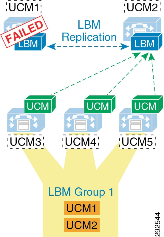
Figure 13-29 shows five Unified CM servers: UCM1 and UCM2 are dedicated LBM servers (only LBM service enabled); UCM3, UCM4, and UCM5 are Unified CM subscribers (Cisco CallManager service enabled). An LBM Group has been configured with UCM1 as active and UCM2 as standby, and it is applied to subscribers UCM3, UCM4, and UCM5. This configuration allows for UCM3, UCM4, and UCM5 to query UCM1 for all bandwidth requests. If UCM1 fails for any reason, the subscribers will fail-over to the standby UCM2. This example is used to illustrate how the LBM Group configuration functions and is not a recommended configuration (see recommendations below).
Because LBM is directly involved in processing requests for every call that is processed by the CallManager service that it is serving, it is important to follow these simple design recommendations in order to ensure optimal functionality of the LBM.
The recommended configuration is to run LBM co-resident with the Cisco CallManager service (call processing). If redundancy of the LBM service is required, it is important not to over-subscribe any given LBM. It is also important to make sure that LBM is no more than a primary and secondary in any given deployment. This means that LBM should not have the load of more than 2 CallManager services during failure scenarios, and the load of only one CallManager service during normal operation. The LBM group can be used to configure a co-resident LBM as the primary, another local (on the same LAN) LBM as secondary, and lastly the service parameter as a failsafe mechanism to ensure that all calls processed by that CallManager service do not fail. There are many reasons for these recommendations. It is difficult, at best, to determine the load of any LBM because it is directly related to the call-processing load of the CallManager service that it is serving. There are also considerations for delay. As soon as an LBM is off-box from a CallManager service, there is an added delay caused by packetization and processing for every call serviced by the CallManager service. Compounding call-processing delay can bring the overall delay budget to an unacceptable level for any given call flow to a ringing state, and result in a poor user experience. Following these design recommendations will reduce the overall call-processing delay.
The order in which the Unified CM Cisco CallManager service uses the LBM is as follows:
Enhanced Location CAC Design and Deployment Recommendations and Considerations
- The Location Bandwidth Manager (LBM) is a Unified CM Feature Service. It is responsible for modeling the topology and servicing Unified CM bandwidth requests.
- LBMs within the cluster create a fully meshed communications network via XML over TCP for the replication of bandwidth change notifications between LBMs.
- Cisco recommends deploying the LBM service co-resident with a Unified CM subscriber running the Cisco CallManager call processing service.
- If redundancy is required for the LBM service, create an LBM Group for each Unified CM subscriber running the Cisco CallManager call processing service. Add the co-resident LBM service as the primary LBM, and the LBM from another Unified CM subscriber on the same LAN as a secondary LBM. This will ensure that the Cisco CallManager call processing service uses the co-resident LBM as primary, the LBM on another local (same LAN) Unified CM subscriber as secondary, and the service parameter Call Treatment when no LBM available as tertiary source for LBM requests.

Note![]() Cisco recommends having LBM back up more than one Cisco CallManager service. Assuming that the LBM is handling the load of the co-resident CallManager service, and during failure of another CallManager service, this would equate to the load of 2 call processing servers on a single LBM.
Cisco recommends having LBM back up more than one Cisco CallManager service. Assuming that the LBM is handling the load of the co-resident CallManager service, and during failure of another CallManager service, this would equate to the load of 2 call processing servers on a single LBM.
- For deployments with cluster over the WAN and local failover, intracluster LBM traffic is already calculated into the WAN bandwidth calculations. See the section on clustering over the WAN Local Failover Deployment Model, for details on bandwidth calculations.
Deducting all Audio from the Voice Pool
Unified CM now has a feature that allows the administrator to deduct the audio bandwidth of video and TelePresence calls from the voice pool. Because ELCAC relies on the correct DSCP setting in order to ensure the protection of the queues that voice and video CAC pools represent, changing how Unified CM deducts bandwidth from the video pool requires the DSCP of audio streams of the video calls to be marked the same as the audio streams of audio-only calls. See the section on Considerations for Audio of Video Calls, for information about aligning admission control with QoS.
In Unified CM this feature is enabled by setting the service parameter Deduct Audio Bandwidth from Audio Pool for Video Call to True under the Call Admission Control section of the CallManager service. False is the default setting, and by default Unified CM deducts both audio and video streams of video calls from the video pool.
Intercluster Enhanced Location CAC
Intercluster Enhanced Location CAC extends the concept of network modeling across multiple clusters. In intercluster Enhanced Location CAC, each cluster manages its locally configured topology of locations and links and then propagates this local topology to other remote clusters that are part of the LBM intercluster replication network. Upon receiving a remote cluster’s topology, the LBM assembles this into its own local topology and creates a global topology. Through this process the global topology is then identical across all clusters, providing each cluster a global view of enterprise network topology for end-to-end CAC. Figure 13-30 illustrates the concept of a global topology with a simplistic hub-and-spoke network topology as an example.
Figure 13-30 Example of a Global Topology for a Simple Hub-and-Spoke Network
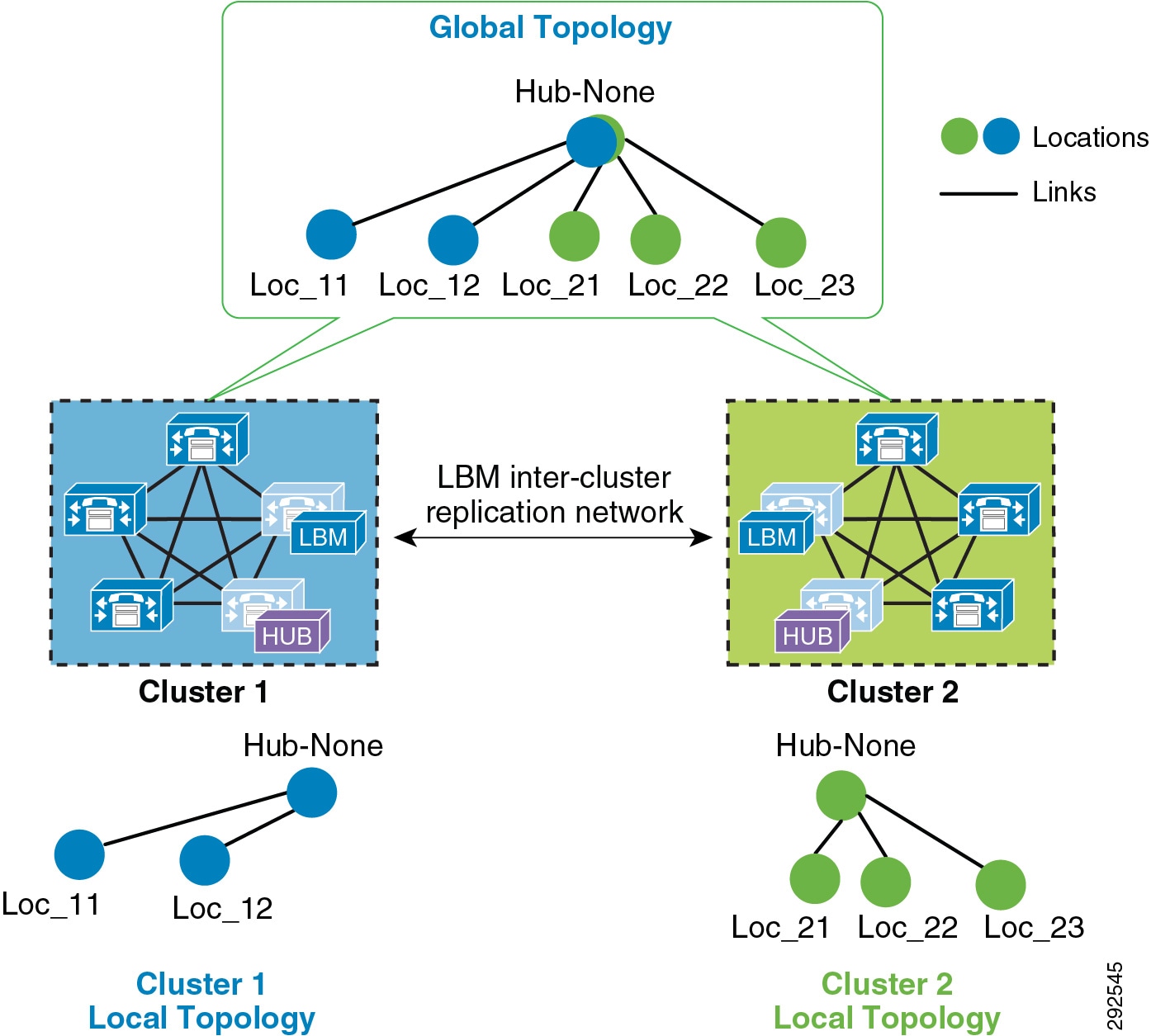
Figure 13-30 shows two clusters, Cluster 1 and Cluster 2, each with a locally configured hub-and-spoke network topology. Cluster 1 has configured Hub_None with links to Loc_11 and Loc_12, while Cluster 2 has configured Hub_None with links to Loc_21, Loc_22, and Loc_23. Upon enabling intercluster Enhanced Location CAC, Cluster 1 sends its local topology to Cluster 2, as does Cluster 2 to Cluster 1. After each cluster obtains a copy of the remote cluster’s topology, each cluster overlays the remote cluster’s topology over their own. The overlay is accomplished through common locations, which are locations that are configured with the same name. Because both Cluster 1 and Cluster 2 have the common location Hub_None with the same name, each cluster will overlay the other's network topology with Hub_None as a common location, thus creating a global topology where Hub_None is the hub and Loc_11, Loc_12, Loc_21, Loc_22 and Loc_23 are all spoke locations. This is an example of a simple network topology, but more complex topologies would be processed in the same way.
LBM Hub Replication Network
The intercluster LBM replication network is a separate replication network of designated LBMs called LBM hubs. LBM hubs create a separate full mesh with one another and replicate their local cluster's topology to other remote clusters. Each cluster effectively receives the topologies from every other remote cluster in order to create a global topology. The designated LBMs for the intercluster replication network are called LBM hubs. The LBMs that replicate only within a cluster are called LBM spokes. The LBM hubs are designated in configuration through the LBM intercluster replication group. The LBM role assignment for any LBM in a cluster can also be changed to a hub or spoke role in the intercluster replication group configuration (For further information on the LBM hub group configuration, refer to the Cisco Unified Communications Manager product documentation available at http://www.cisco.com/en/US/products/sw/voicesw/ps556/tsd_products_support_series_home.html.)
In the LBM intercluster replication group, there is also a concept of bootstrap LBM. Bootstrap LBMs are LBM hubs that provide all other LBM hubs with the connectivity details required to create the full-mesh hub replication network. Bootstrap LBM is a role that any LBM hub can have. If all LBM hubs point to a single LBM hub, that single LBM hub will tell all other LBM hubs how to connect to one another. Each replication group can reference up to three bootstrap LBMs.
Once the LBM hub group is configured on each cluster, the designated LBM hubs will create the full-mesh intercluster replication network. Figure 13-31 illustrates an intercluster replication network configuration with LBM hub groups set up between three clusters (Leaf Cluster 1, Leaf Cluster 2, and a Session Management Edition (SME) cluster) to form the intercluster replication network. The SME cluster is used here only as an example and is not required for this specific setup. The SME cluster could simply be another regular cluster handling endpoint registrations.
Figure 13-31 Example Intercluster Replication Network for Three Clusters
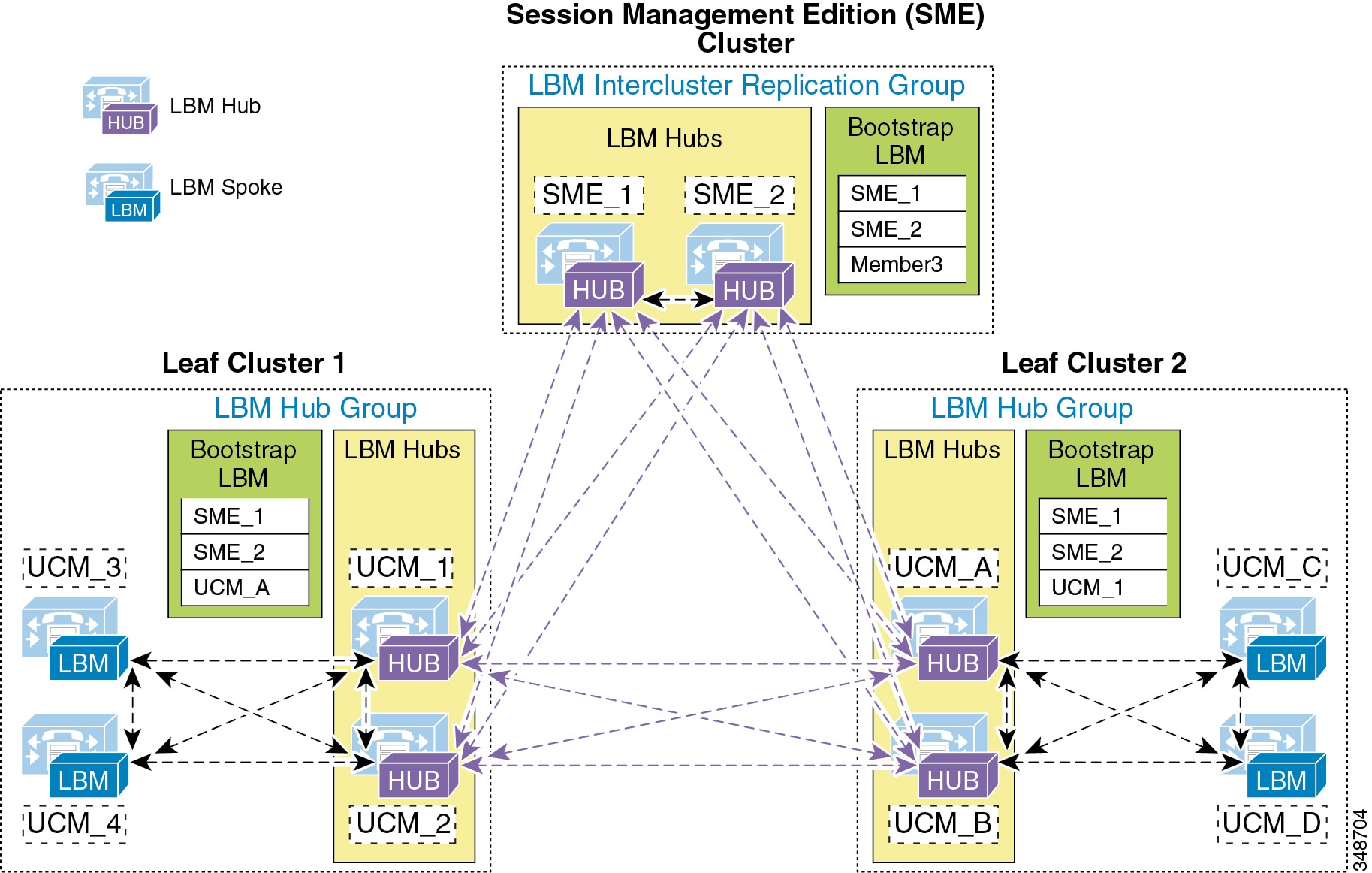
In Figure 13-31, two LBMs from each cluster have been designated as the LBM hubs for their cluster. These LBM hubs form the intercluster LBM replication network. The bootstrap LBMs configured in each LBM intercluster replication group are designated as SME_1 and SME_2. These two LBM hubs from the SME cluster serve as points of contact or bootstrap LBMs for the entire intercluster LBM replication network. This means that each LBM in each cluster connects to SME_1, replicates its local topology to SME_1, and gets the remote topology from SME_1. They also get the connectivity information for the other leaf clusters from SME_1, connect to the other remote clusters, and replicate their topologies. This creates the full-mesh replication network. If SME_1 is unavailable, the LBM hubs will connect to SME_2. If SME_2 is unavailable, Leaf Cluster 1 LBMs will connect to UCM_A and Leaf Cluster 2 LBMs will connect to UCM_1 as a backup measure in case the SME cluster is unavailable. This is just an example configuration to illustrate the components of the intercluster LBM replication network.
The LBM has the following roles with respect to the LBM intercluster replication network:
–![]() Remote LBM hubs responsible for interconnecting all LBM hubs in the replication network
Remote LBM hubs responsible for interconnecting all LBM hubs in the replication network
–![]() Can be any hub in the network
Can be any hub in the network
–![]() Can indicate up to three bootstrap LBM hubs per LBM intercluster replication group
Can indicate up to three bootstrap LBM hubs per LBM intercluster replication group
–![]() Communicate directly to other remote hubs as part of the intercluster LBM replication network
Communicate directly to other remote hubs as part of the intercluster LBM replication network
–![]() Communicate directly to local LBM hubs in the cluster and indirectly to the remote LBM hubs through the local LBM hubs
Communicate directly to local LBM hubs in the cluster and indirectly to the remote LBM hubs through the local LBM hubs
–![]() LBM optimizes the LBM messages by choosing a sender and receiver from each cluster.
LBM optimizes the LBM messages by choosing a sender and receiver from each cluster.
–![]() The LBM sender and receiver of the cluster is determined by lowest IP address.
The LBM sender and receiver of the cluster is determined by lowest IP address.
–![]() The LBM hubs that receive messages from remote clusters, in turn forward the received messages to the LBM spokes in their local cluster.
The LBM hubs that receive messages from remote clusters, in turn forward the received messages to the LBM spokes in their local cluster.
LBM hubs can also be configured to encrypt their communications. This allows intercluster ELCAC to be deployed in environments where it is critical to encrypt traffic between clusters because the links between clusters might reside over unprotected networks. For further information on configuring encrypted signaling between LBM hubs, refer to the Cisco Unified Communications Manager product documentation available at
http://www.cisco.com/en/US/products/sw/voicesw/ps556/tsd_products_support_series_home.html
Common Locations (Shared Locations) and Links
As mentioned previously, common locations are locations that are named the same across clusters. Common locations play a key role in how the LBM creates the global topology and how it associates a single location across multiple clusters. A location with the same name between two or more clusters is considered the same location and is thus a shared location across those clusters. So if a location is meant to be shared between multiple clusters, it is required to have exactly the same name. After replication, the LBM will check for configuration discrepancies across locations and links. Any discrepancy in bandwidth value or weight between common locations and links can be seen in serviceability, and the LBM calculates the locations and link paths with the most restrictive values for bandwidth and the lowest value (least cost) for weight.
Common locations and links can be configured across clusters for a number of different reasons. You might have a number of clusters that manage devices in the same physical site and use the same WAN uplinks, and therefore the same location needs to be configured on each cluster in order to associate that location to the local devices on each cluster. You might also have clusters that manage their own topology, yet these topologies interconnect at specific locations and you will have to configure these locations as common locations across each cluster so that, when the global topology is being created, the clusters have the common interconnecting locations and links on each cluster to link each remote topology together effectively. Figure 13-32 illustrates linking topologies together and shows the common topology that each cluster shares.
Figure 13-32 Using Common Locations and Links to Create a Global Topology
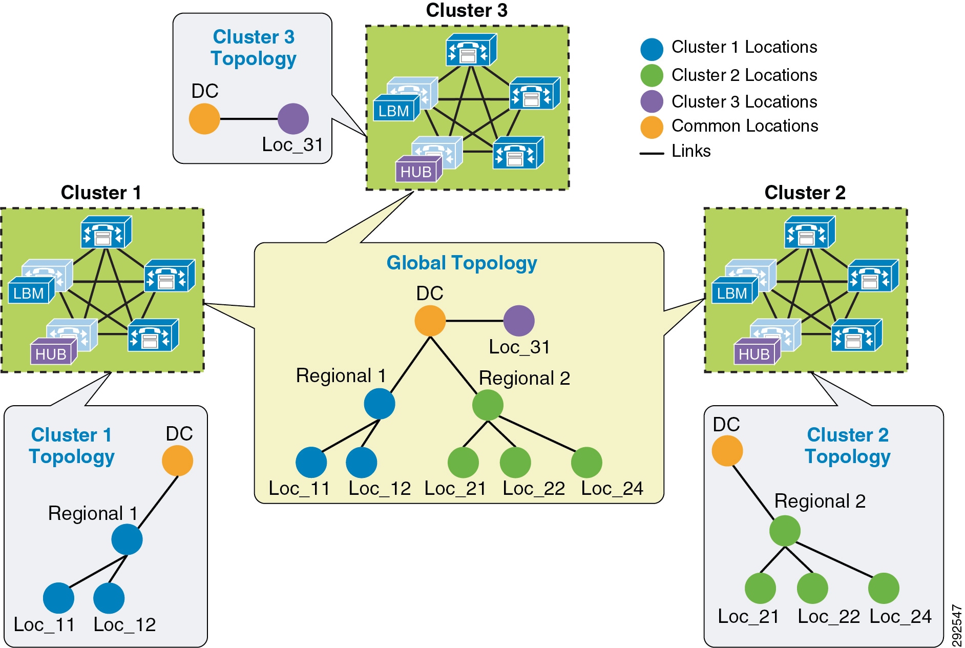
In Figure 13-32, Cluster 1 has devices in locations Regional 1, Loc_11, and Loc_12, but it requires configuring DC and a link from Regional 1 to DC in order to link to the rest of the global topology. Cluster 2 is similar, with devices in Regional 2 and Loc_21, Loc_22, and Loc_23, and it requires configuring DC and a link from DC to Regional 2 to map into the global topology. Cluster 3 has devices in Loc_31 only, and it requires configuring DC and a link to DC from Loc_31 to map into Cluster 1 and Cluster 2 topologies. Alternatively, Regional 1 and Regional 2 could be the common locations configured on all clusters instead of DC, as is illustrated in Figure 13-33.
Figure 13-33 Alternative Topology Using Different Common Locations
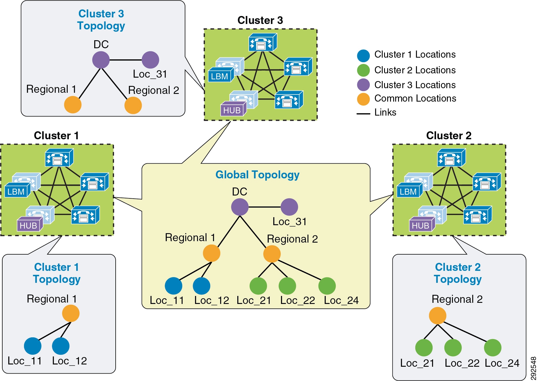
The key to topology mapping from cluster to cluster is to ensure that at least one cluster has a common location with another cluster so that the topologies interconnect accordingly.
Shadow Location
The shadow location is used to enable a SIP trunk to pass Enhanced Location CAC information such as location name and Video-Traffic-Class (discussed below), among other things, required for Enhanced Location CAC to function between clusters. In order to pass this location information across clusters, the SIP intercluster trunk (ICT) must be assigned to the "shadow" location. The shadow location cannot have a link to other locations, and therefore no bandwidth can be reserved between the shadow location and other locations. Any device other than a SIP ICT that is assigned to the shadow location will be treated as if it was associated to Hub_None. That is important to know because if a device other than a SIP ICT ends up in the shadow location, bandwidth deductions will be made from that device as if it were in Hub_None, and that could have varying effects depending on the location and links configuration.
When the SIP ICT is enabled for Enhanced Location CAC, it passes information in the SIP Call-Info header that allows the originating and terminating clusters to process the location bandwidth deductions end-to-end. Figure 13-34 illustrates an example of a call between two clusters and some details about the information passed. This is only to illustrate how location information is passed from cluster to cluster and how bandwidth deductions are made.
Figure 13-34 Location Information Passed Between Clusters over SIP
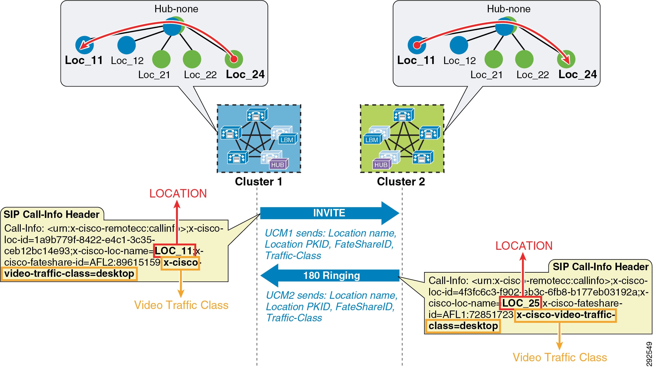
In Figure 13-34, Cluster 1 sends an invite to Cluster 2 and populates the call-info header with the calling parties location name and Video-Traffic-Class, among other pertinent information such as unique call-ID. When Cluster 2 receives the invite with the information, it looks up the terminating party and performs a CAC request on the path between the calling party’s and called party’s locations from the global topology that it has in memory from LBM replication. If it is successful, Cluster 2 will replicate the reservation and extend the call to the terminating device and return a 180 ringing with the location information of the called party back to Cluster 1. When Cluster 1 receives the 180 ringing, it gets the terminating device’s location name and goes through the same bandwidth lookup process using the same unique call-ID that it calculates from the information passed in the call-info header. If it is successful, it too continues with the call flow. Because both clusters use the same information in the call-info header, they will deduct bandwidth for the same call using the same call-ID, thus avoiding any double bandwidth deductions.
Location and Link Management Cluster
In order to avoid configuration overhead, a Location and Link Management Cluster can be configured to manage all locations and links in the global topology. All other clusters uniquely configure the locations that they require for location-to-device association and do not configure links or any bandwidth values other than unlimited. It should be noted that the Location and Link Management Cluster is a design concept and is simply any cluster that is configured with the entire global topology of locations and links, while all other clusters in the LBM replication network are configured only with locations set to unlimited bandwidth values and without configured links. When intercluster Enhanced Location CAC is enabled and the LBM replication network is configured, all clusters replicate their view of the network. The designated Location and Link Management Cluster has the entire global topology with locations, links, and bandwidth values; and once those values are replicated, all clusters use those values because they are the most restrictive. This design alleviates configuration overhead in deployments where a large number of common locations are required across multiple clusters.
–![]() One cluster should be chosen as the management cluster (the cluster chosen to manage locations and links).
One cluster should be chosen as the management cluster (the cluster chosen to manage locations and links).
–![]() The management cluster should be configured with the following:
The management cluster should be configured with the following:
All locations within the enterprise will be configured in this cluster.
All bandwidth values and weights for all locations and links will be managed in this cluster.
–![]() All other clusters in the enterprise should configure only the locations required for association to devices but should not configure the links between locations. This link information will come from the management cluster when intercluster Enhanced Location CAC is enabled.
All other clusters in the enterprise should configure only the locations required for association to devices but should not configure the links between locations. This link information will come from the management cluster when intercluster Enhanced Location CAC is enabled.
–![]() When intercluster Enhanced Location CAC is enabled, all of the locations and links will be replicated from the management cluster and LBM will use the lowest, most restrictive bandwidth and weight value.
When intercluster Enhanced Location CAC is enabled, all of the locations and links will be replicated from the management cluster and LBM will use the lowest, most restrictive bandwidth and weight value.
- LBM will always use the lowest most restrictive bandwidth and lowest weight value after replication.
- Manage enterprise CAC topology from a single cluster.
- Alleviates location and link configuration overhead when clusters share a large number of common locations.
- Alleviates configuration mistakes in locations and links across clusters.
- Other clusters in the enterprise require the configuration only of locations needed for location-to-device and endpoint association.
- Provides a single cluster for monitoring of the global locations topology.
Figure 13-35 illustrates Cisco Unified Communications Manager Session Management Edition (SME) as a Location and Link Management Cluster for three leaf clusters.

Note![]() As mentioned, any cluster can act as the Location and Link management cluster. In this example SME is the Location and Link management cluster.
As mentioned, any cluster can act as the Location and Link management cluster. In this example SME is the Location and Link management cluster.
Figure 13-35 Example of SME as a Location and Link Management Cluster
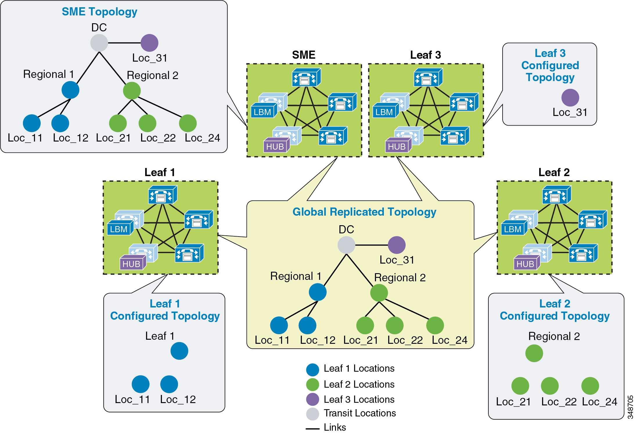
In Figure 13-35 there are three leaf clusters, each with devices in only a regional and remote locations. SME has the entire global topology configured with locations and links, and intercluster LBM replication is enabled between all four clusters. None of the clusters in this example share locations, although all of the locations are common locations because SME has configured the entire location and link topology. Note that Leaf 1, Leaf 2, and Leaf 3 configure only locations that they require to associate to devices and endpoints, while SME has the entire global topology configured. After intercluster replication, all clusters will have the global topology.
Intercluster Enhanced Location CAC Design and Deployment Recommendations and Considerations
- A cluster requires the location to be configured locally for location-to-device association.
- Each cluster should be configured with the immediately neighboring locations so that each cluster’s topology can inter-connect. This does not apply to Location and Link Management Cluster deployments.
- Links need to be configured to establish points of interconnect between remote topologies. This does not apply to Location and Link Management Cluster deployments.
- Discrepancies of bandwidth limits and weights on common locations and links are resolved by using the lowest bandwidth and weight values.
- Naming locations consistently across clusters is critical. Follow the practice, "Same location, same name; different location, different name."
- The Hub_None location should be renamed to be unique in each cluster or else it will be a common (shared) location by other clusters.
- Cluster-ID should be unique on each cluster for serviceability reports to be usable.
- All LBM hubs are fully meshed between clusters.
- An LBM hub is responsible for communicating to hubs in remote clusters.
- An LBM spoke does not directly communicate with other remote clusters. LBM spokes receive and send messages to remote clusters through the Local LBM Hub.
- LBM Hub Groups
–![]() Used to assign LBMs to the Hub role
Used to assign LBMs to the Hub role
–![]() Used to define three remote hub members that replicate hub contact information for all of the hubs in the LBM hub replication network
Used to define three remote hub members that replicate hub contact information for all of the hubs in the LBM hub replication network
–![]() An LBM is a hub when it is assigned to an LBM hub group.
An LBM is a hub when it is assigned to an LBM hub group.
–![]() An LBM is a spoke when it is not assigned to an LBM hub group.
An LBM is a spoke when it is not assigned to an LBM hub group.
Enhanced Location CAC for TelePresence Immersive Video
Since TelePresence endpoints now provide a diverse range of collaborative experiences from the desktop to the conference room, Enhanced Location CAC includes support to provide CAC for TelePresence immersive video calls. This section discusses the features in Enhanced Location CAC that support TelePresence immersive video CAC.
Video Call Traffic Class
Video Call Traffic Class is an attribute that is assigned to all endpoints, and that can also be enabled on SIP trunks, to determine the video classification type of the endpoint or trunk. This enables Unified CM to classify various call flows as either immersive, desktop video, or both, and to deduct accordingly from the appropriate location and/or link bandwidth allocations of video bandwidth, immersive bandwidth, or both. For TelePresence endpoints there is a non-configurable Video Call Traffic Class of immersive assigned to the endpoint. A SIP trunk can be classified as desktop, immersive, or mixed video in order to deduct bandwidth reservations of a SIP trunk call. All other endpoints and trunks have a non-configurable Video Call Traffic Class of desktop video. More detail on endpoint and trunk classification is provided in the subsections below.
TelePresence immersive endpoints mark their media with a DSCP value of CS4 by default, and desktop video endpoints mark their media with AF41 by default, as per recommended QoS settings. For Cisco endpoints this is accomplished through the configurable Unified CM QoS service parameters DSCP for Video calls and DSCP for TelePresence calls. When a Cisco TelePresence endpoint registers with Unified CM, it downloads a configuration file and applies the QoS setting of DSCP for TelePresence calls. When a Unified Communications video-capable endpoint registers with Unified CM, it downloads a configuration file and applies the QoS setting of DSCP for Video calls. All third-party video endpoints require manual configuration of the endpoints themselves and are statically configured, meaning they do not change QoS marking depending on the call type; therefore, it is important to match the Enhanced Location CAC bandwidth allocation to the correct DSCP. Unified CM achieves this by deducting desktop video calls from the Video Bandwidth location and link allocation for devices that have a Video Call Traffic Class of desktop. End-to-end TelePresence immersive video calls are deducted from the Immersive Video Bandwidth location and link allocation for devices or trunks with the Video Call Traffic Class of immersive. This ensures that end-to-end desktop video and immersive video calls are marked correctly and counted correctly for call admission control. For calls between desktop devices and TelePresence immersive devices, bandwidth is deducted from both the Video Bandwidth and the Immersive Video Bandwidth location and link allocations.
Endpoint Classification
Cisco TelePresence endpoints have a fixed non-configurable Video Call Traffic Class of immersive and are identified by Unified CM as immersive. Telepresence endpoints are defined in Unified CM by the device type. When a device is added in Unified CM, any device with TelePresence in the name of the device type is classified as immersive, as are the generic single-screen and multi-screen room systems. Another way to check the capabilities of the endpoints in the Unified CM is to go to the Cisco Unified Reporting Tool > System Reports > Unified CM Phone Feature List. In the feature drop down list, select Immersive Video Support for TelePresence Devices ; in the product drop down list, select All. This will display all of the device types that are classified as immersive. All other endpoints have a fixed Video Call Traffic Class of desktop due to their lack of the non-configurable immersive attribute.
Bandwidth reservations are determined by the classification of endpoints in a video call, and they deduct bandwidth from the locations and links bandwidth pools as listed in Table 13-12 .
|
|
|
|
|---|---|---|
SIP Trunk Classification
A SIP trunk can also be classified as desktop, immersive, or mixed video in order to deduct bandwidth reservations of a SIP trunk call, and the classification is determined by the calling device type and Video Call Traffic Class of the SIP trunk. The SIP trunk can be configured through the SIP Profile trunk-specific information as:
- Immersive — High-definition immersive video
- Desktop — Standard desktop video
- Mixed — A mix of immersive and desktop video
A SIP trunk can be classified with any of these three classifications and is used primarily to classify Video or TelePresence Multipoint Control Units (MCUs), a video device at a fixed location, a Unified CM cluster supporting traditional Location CAC, or a Cisco TelePresence System Video Communications Server (VCS).
Bandwidth reservations are determined by the classification of an endpoint and a SIP trunk in a video call, and they deduct bandwidth from the locations and links bandwidth pools as listed in Table 13-13 .
|
|
|
|
|---|---|---|
By default, all video calls from either immersive or desktop endpoints are deducted from the locations and links video bandwidth pool. To change this behavior, set Unified CM’s CallManager service parameter Use Video BandwidthPool for Immersive Video Calls to False, and this will enable the immersive video bandwidth deductions. After this is enabled, immersive and desktop video calls will be deducted out of their respective pools.
As described earlier, a video call between a Unified Communications video endpoint (desktop Video Call Traffic Class) and a TelePresence endpoint (immersive Video Call Traffic Class) will mark their media asymmetrically and, when immersive video CAC is enabled, will deduct bandwidth from both video and immersive locations and links bandwidth pools. Figure 13-36 illustrates this.
Figure 13-36 Enhanced Location CAC Bandwidth Deductions and Media Marking for a Multi-Site Deployment
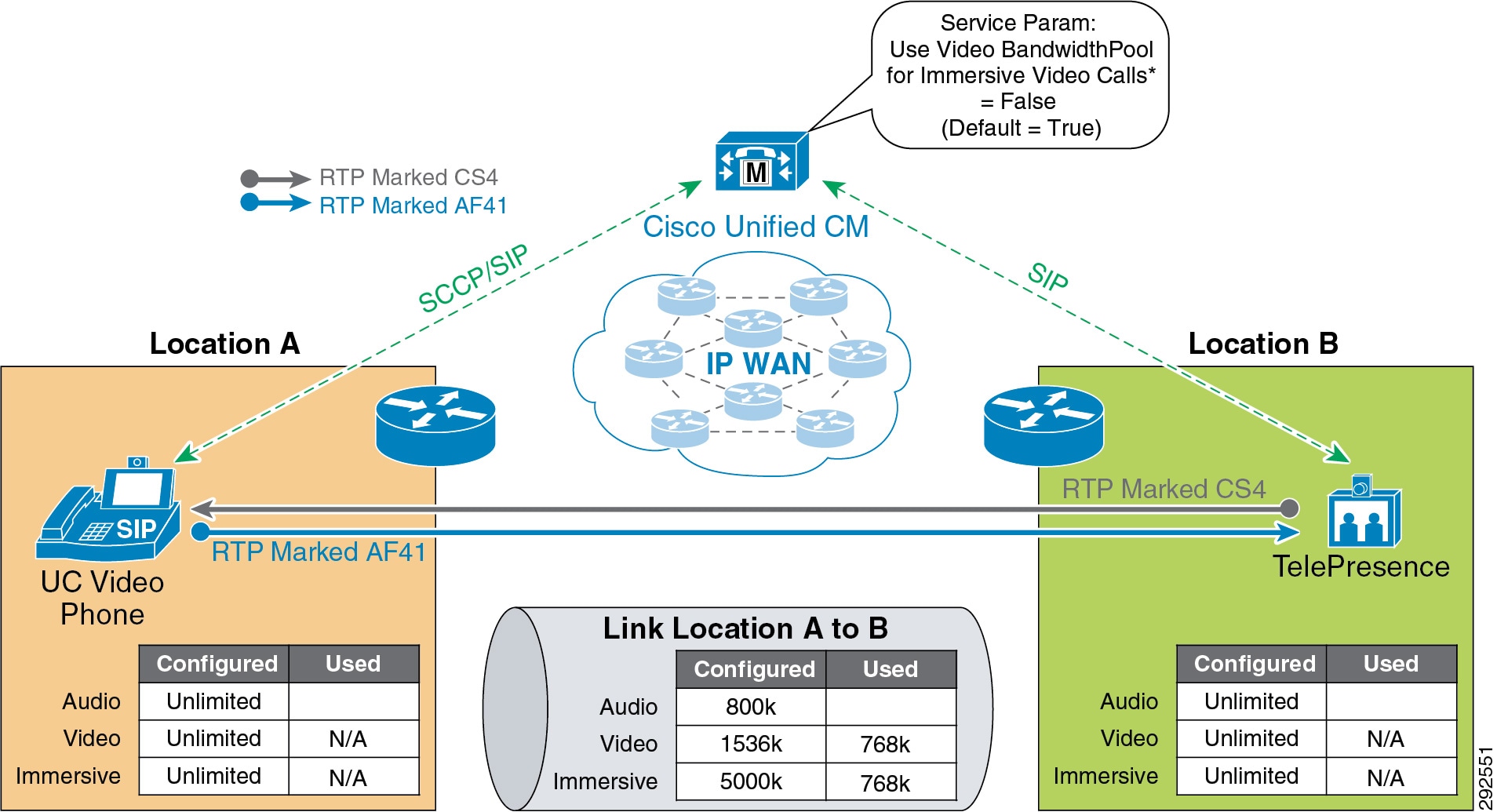
Examples of Various Call Flows and Location and Link Bandwidth Pool Deductions
The following call flows depict the expected behavior of locations and links bandwidth deductions when the Unified CM service parameter Use Video BandwidthPool for Immersive Video Calls is set to False.
Figure 13-37 illustrates an end-to-end TelePresence immersive video call between TP-A in Location L1 and TP-B in Location L2. End-to-end immersive video endpoint calls deduct bandwidth from the immersive bandwidth pool of the locations and the links along the effective path.
Figure 13-37 Call Flow for End-to-End TelePresence Immersive Video
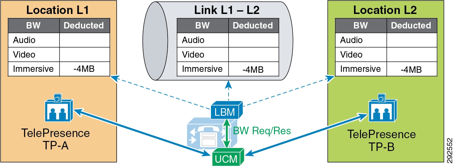
Figure 13-38 illustrates an end-to-end desktop video call between DP-A in Location L1 and DP-B in Location L2. End-to-end desktop video endpoint calls deduct bandwidth from the video bandwidth pool of the locations and the links along the effective path.
Figure 13-38 Call Flow for End-to-End Desktop Video
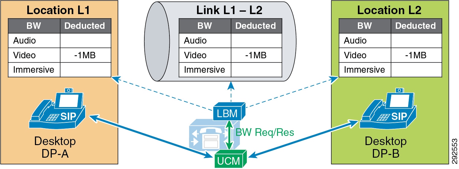
Figure 13-39 illustrates a video call between desktop video endpoint DP-A in Location L1 and TelePresence video endpoint TP-B in Location L2. Interoperating calls between desktop video endpoints and TelePresence video endpoints deduct bandwidth from both video and immersive locations and the links bandwidth pools along the effective path.
Figure 13-39 Call Flow for Desktop-to-TelePresence Video
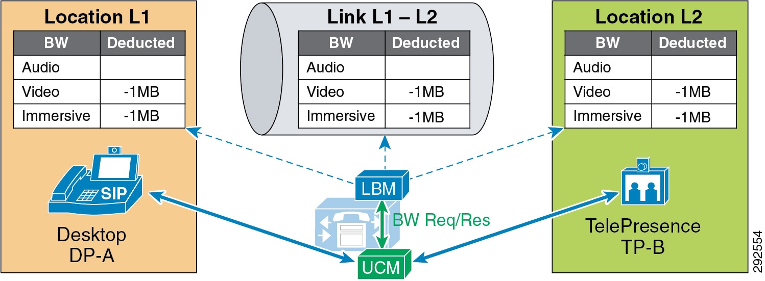
In Figure 13-40, a desktop video endpoint and two TelePresence endpoints call a SIP trunk configured with a Video Traffic Class of immersive that points to a TelePresence MCU. Bandwidth is deducted along the effective path from the immersive locations and the links bandwidth pools for the calls that are end-to-end immersive and from both video and immersive locations and the links bandwidth pools for the call that is desktop-to-immersive.
Figure 13-40 Call Flow for a Video Conference with an MCU
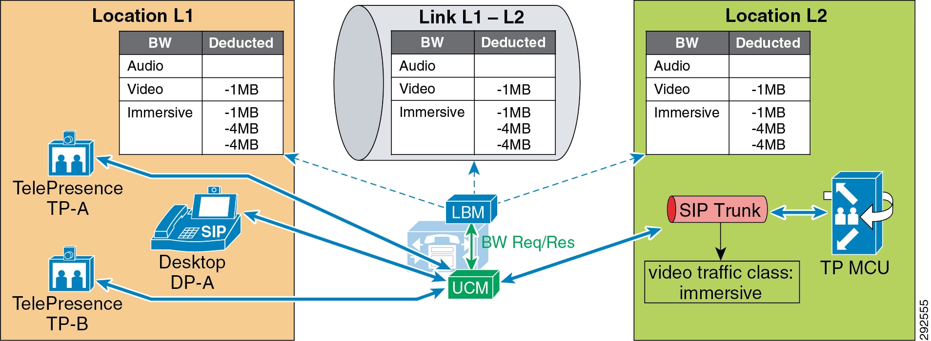
Figure 13-41 illustrates an end-to-end immersive video call across clusters, which deducts bandwidth from the immersive bandwidth pool of the locations and links along the effective path.
Figure 13-41 Call Flow for End-to-End TelePresence Immersive Video Across Clusters

Figure 13-42 illustrates an end-to-end desktop video call across clusters, which deducts bandwidth from the video bandwidth pool of the locations and links along the effective path.
Figure 13-42 Call Flow for End-to-End Desktop Video Call Across Clusters

Figure 13-43 illustrates a desktop video endpoint calling a TelePresence endpoint across clusters. the call deducts bandwidth from both video and immersive bandwidth pools of the locations and links along the effective path.
Figure 13-43 Call Flow for Desktop-to-TelePresence Video Across Clusters

Video Bandwidth Utilization and Admission Control
When Unified CM negotiates an audio or video call, a number of separate streams are established between the endpoints involved in the call. For video calls with content sharing, this can result in as many as 8 (or possibly more) unidirectional streams. For an audio-only call typically the bare minimum is 2 streams, one in each direction. This section discusses bandwidth utilization on the network and how Unified CM accounts for this in admission control bandwidth accounting.
For the purpose of the discussion in this section, please note the following:
- The figures in this section use a bidirectional arrow (<-->) to represent two unidirectional streams.
- The following points summarize how Unified CM Enhanced Location CAC deducts bandwidth from the configured audio, video, and immersive allocations. For more information, see the section on Locations and Links:
–![]() Audio (audio-only calls): RTP bit rate + IP and UDP header overhead
Audio (audio-only calls): RTP bit rate + IP and UDP header overhead
–![]() Video (video calls): RTP bit rate only
Video (video calls): RTP bit rate only
–![]() Immersive (video calls by Cisco TelePresence endpoints): RTP bit rate only
Immersive (video calls by Cisco TelePresence endpoints): RTP bit rate only
–![]() Bandwidth deductions are made for bidirectional RTP streams and are assumed to be symmetrically routed (both streams routed over the same path). For example, a G.711 audio call of 80 kbps is 80 kbps in each direction over a full-duplex network; that is 80 kbps on the transmit pair of wires and 80 kbps on the receive pair of wires, equating to 80 kbps full-duplex. (See Figure 13-44.) Note that traffic is not always routed symmetrically in the WAN. Check with your network administrator when necessary to ensure that admission control is correctly accounting for the media as it is routed in the network over the WAN.
Bandwidth deductions are made for bidirectional RTP streams and are assumed to be symmetrically routed (both streams routed over the same path). For example, a G.711 audio call of 80 kbps is 80 kbps in each direction over a full-duplex network; that is 80 kbps on the transmit pair of wires and 80 kbps on the receive pair of wires, equating to 80 kbps full-duplex. (See Figure 13-44.) Note that traffic is not always routed symmetrically in the WAN. Check with your network administrator when necessary to ensure that admission control is correctly accounting for the media as it is routed in the network over the WAN.
–![]() Real-Time Transport Control Protocol (RTCP) bandwidth overhead is not part of Unified CM bandwidth allocation and should be part of network provisioning. RTCP is quite common in most call flows and is commonly used for statistical information about the streams. It is also used to synchronize audio in video calls to ensure proper lip-sync. In some cases it can be enabled or disabled on the endpoint. RFC 3550 recommends that the fraction of the session bandwidth added for RTCP should be fixed at 5%. What this means is that it is common practice for the RTCP session to be up to 5% of the associated RTP session. So when calculating bandwidth consumption on the network, you should add the RTCP overhead for each RTP session. For example, if you have a G.711 audio call of 80 kbps with RTCP enabled, you will be using up to 84 kbps per session (4 kbps RTCP overhead) for both RTP and RTCP. This calculation is not part of Enhanced Location CAC deductions but should be part of network provisioning.
Real-Time Transport Control Protocol (RTCP) bandwidth overhead is not part of Unified CM bandwidth allocation and should be part of network provisioning. RTCP is quite common in most call flows and is commonly used for statistical information about the streams. It is also used to synchronize audio in video calls to ensure proper lip-sync. In some cases it can be enabled or disabled on the endpoint. RFC 3550 recommends that the fraction of the session bandwidth added for RTCP should be fixed at 5%. What this means is that it is common practice for the RTCP session to be up to 5% of the associated RTP session. So when calculating bandwidth consumption on the network, you should add the RTCP overhead for each RTP session. For example, if you have a G.711 audio call of 80 kbps with RTCP enabled, you will be using up to 84 kbps per session (4 kbps RTCP overhead) for both RTP and RTCP. This calculation is not part of Enhanced Location CAC deductions but should be part of network provisioning.

Note![]() There are, however, methods to re-mark this traffic to another Differentiated Services Code Point (DSCP). For example, RTCP uses odd-numbered UDP ports while RTP uses even-numbered UDP ports. Therefore, classification based on UDP port ranges is possible. Network-Based Application Recognition (NBAR) is another option as it allows for classification and re-marking based on the RTP header Payload Type field. For more information on NBAR, see http://www.cisco.com. However, if the endpoint marking is trusted in the network, then RTCP overhead should be provisioned in the network within the same QoS class as audio RTP (default marking is EF). It should also be noted that RTCP is marked by the endpoint with the same marking as RTP; by default this is EF (verify that RTCP is also marked as EF).
There are, however, methods to re-mark this traffic to another Differentiated Services Code Point (DSCP). For example, RTCP uses odd-numbered UDP ports while RTP uses even-numbered UDP ports. Therefore, classification based on UDP port ranges is possible. Network-Based Application Recognition (NBAR) is another option as it allows for classification and re-marking based on the RTP header Payload Type field. For more information on NBAR, see http://www.cisco.com. However, if the endpoint marking is trusted in the network, then RTCP overhead should be provisioned in the network within the same QoS class as audio RTP (default marking is EF). It should also be noted that RTCP is marked by the endpoint with the same marking as RTP; by default this is EF (verify that RTCP is also marked as EF).
Figure 13-44 A Basic Audio-Only Call with RTCP Enabled

In Figure 13-44 two desktop video phones have established an audio-only call. In this call flow four streams are negotiated: two audio streams illustrated by a single bidirectional arrow and two RTCP streams also illustrated by a bidirectional arrow. For this call, the Location Bandwidth Manager (LBM) deducts 80 kbps (bit rate + IP/UDP overhead) between location L1 and location L2 for a call established between desktop phones DP-A and DP-B. The actual bandwidth consumed at Layer 3 in the network with RTCP enabled would be between 80 kbps and 84 kbps, as discussed previously in this section.
In Figure 13-45 two desktop video phones have established a video call. In this call flow eight streams are negotiated: two audio streams, two audio-associated RTCP streams, two video streams, and two video-associated RTCP streams. Again for this illustration one bidirectional arrow is used to depict two unidirectional streams. This particular call is 1024 kbps, with 64 kbps of G.711 audio and 960 kbps of video (bit rate only for audio and video allocations of video calls). So in this case the LBM deducts 1024 kbps between locations L1 and L2 for a video call established between desktop phones DP-A and DP-B. RTCP is overhead that should be accounted for in provisioning, depending on how it is marked or re-marked by the network.
Figure 13-45 A Basic Video Call with RTCP Enabled
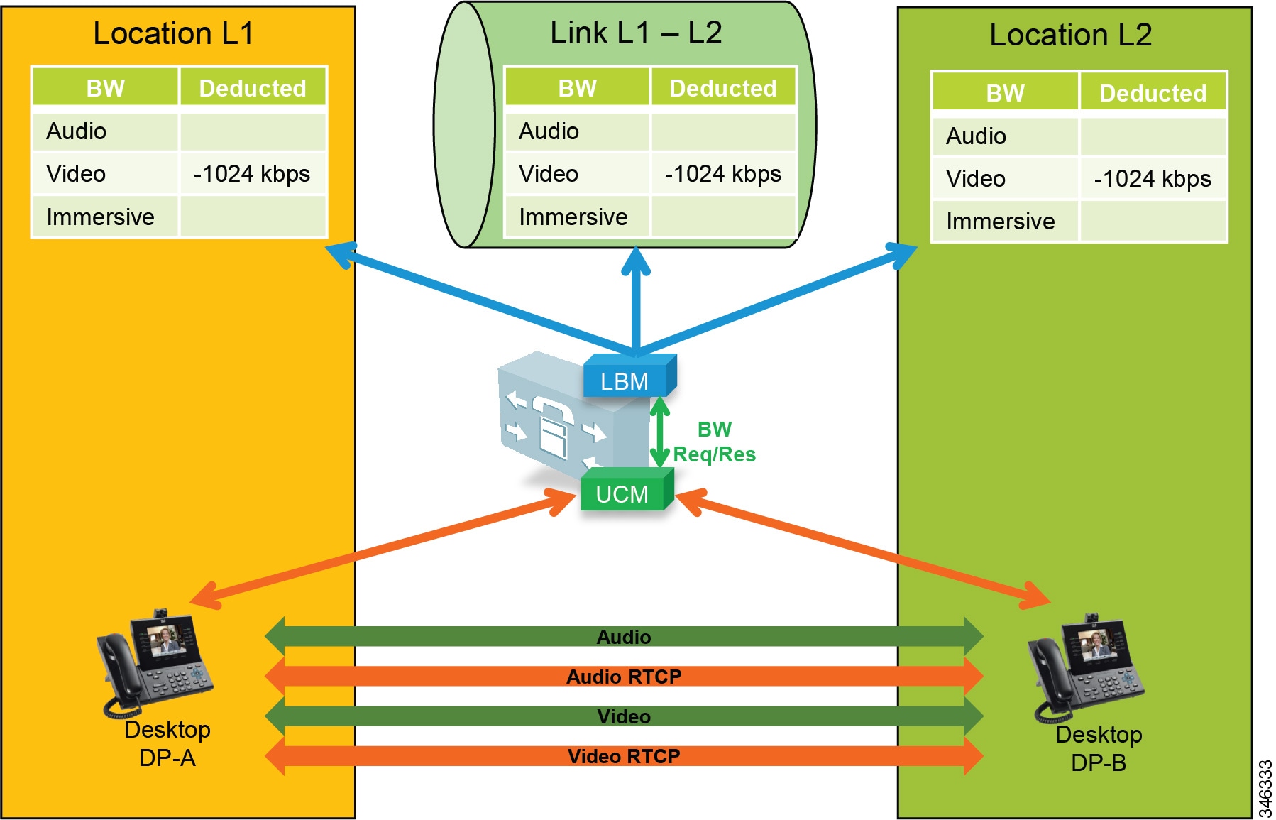
The example in Figure 13-46 is of a video call with presentation sharing. This is a more complex call with regard to the number of associated streams and bandwidth allocation when compared to bandwidth used on the network, and therefore it must be provisioned in the network. Figure 13-46 illustrates a video call with RTCP enabled and Binary Floor Control Protocol (BFCP) enabled for presentation sharing. All SIP-enabled telepresence multipurpose or personal endpoints such as a the Cisco TelePresence System EX, MX, SX, C, and Profile Series function in the same manner.
Figure 13-46 Video Call with RTCP and BFCP Enabled and Presentation Sharing
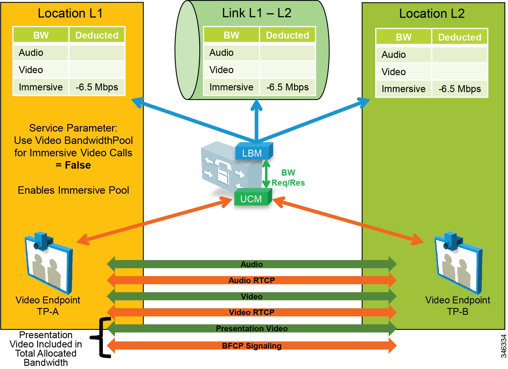
When a video call is established between two video endpoints, audio and video streams are established and bandwidth is deducted for the negotiated rate. Unified CM uses regions to determine the maximum bit rate for the call. For example, with a Cisco TelePresence System EX90 at the highest detail of 1080p at 30 frames per second (fps), the negotiated rate between regions would have to be set at 6.5 Mbps. EX90s used in this scenario would average around 6.1 Mbps for this session. When the endpoints start presentation sharing during the session, BFCP is negotiated between the endpoints and a new video stream is enabled at either 5 fps or 30 fps, depending on endpoint configuration. When this occurs, the endpoints will throttle down their main video stream to include the presentation video so that the entire session does not use more than the allocated bandwidth of 6.5 Mbps. Thus, the average bandwidth consumption remains the same with or without presentation sharing.

Note![]() The presentation video stream is typically unidirectional in the direction of the person or persons viewing the presentation.
The presentation video stream is typically unidirectional in the direction of the person or persons viewing the presentation.
Telepresence immersive and office endpoints such as the Cisco TelePresence System 500, 1000, 3000, and TX9000 Series that negotiate a call between one another function a little differently in the sense that the video for presentation sharing is an additional bandwidth above and beyond what is allocated for the main video session, and thus it is not deducted from Enhanced Location CAC. Figure 13-47 illustrates this.
Figure 13-47 Video Call with RTCP and BFCP Enabled and Presentation
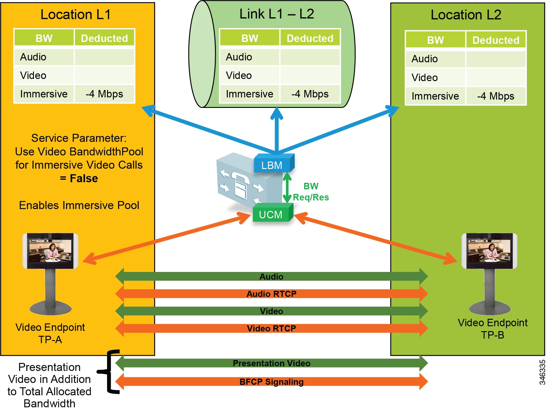
In Figure 13-47 the telepresence immersive video endpoints establish a video call and enable presentation sharing. The LBM deducts 4 Mbps for the main audio and video session from the immersive pool for the call, and video is established between the endpoints. When presentation sharing is activated, the two endpoints exchange BFCP and negotiate a presentation video stream at 5 fps or 30 fps in one direction, depending on the endpoint configuration. At 5 fps the average bandwidth used is approximately 500 kbps of additional bandwidth overhead. This bandwidth is above and beyond the 4 Mbps that was allocated for the video call and should be provisioned in the network. At 30 fps the average bit rate of the presentation video is approximately 1.5 Mbps.

Note![]() The Cisco TelePresence System endpoints use Telepresence Interoperability Protocol (TIP) to multiplex multiple screens and audio into two audio and video RTP streams in each direction. Therefore the actual streams on the wire may be different than what is expressed in the illustration, but the concept of additional bandwidth overhead for the presentation video is the same.
The Cisco TelePresence System endpoints use Telepresence Interoperability Protocol (TIP) to multiplex multiple screens and audio into two audio and video RTP streams in each direction. Therefore the actual streams on the wire may be different than what is expressed in the illustration, but the concept of additional bandwidth overhead for the presentation video is the same.
Upgrade and Migration from Location CAC to Enhanced Location CAC
Upgrading to Cisco Unified CM from a previous release that supports only traditional Location CAC, will result in the migration of Location CAC to Enhanced Location CAC. The migration consists of taking all previously defined locations bandwidth limits of audio and video bandwidth and migrating them to a link between the user-defined location and Hub_None. This effectively recreates the hub-and-spoke model that previous versions of Unified CM Location CAC supported. Figure 13-48 illustrates the migration of bandwidth information.
Figure 13-48 Migration from Location CAC to Enhanced Location CAC After Unified CM Upgrade

Settings after an upgrade to a Cisco Unified CM release that supports Enhanced Location CAC:
- The LBM is activated on each Unified CM subscriber running the Cisco CallManager service.
- The Cisco CallManager service communicates directly with the local LBM.
- No LBM group or LBM hub group is created.
- All LBM services are fully meshed.
- Intercluster Enhanced Location CAC is not enabled.
- All intra-location bandwidth values are set to unlimited.
- Bandwidth values assigned to locations are migrated to a link connecting the user-defined location and Hub_None.
- Immersive bandwidth is set to unlimited.
- A shadow location is created.
- Phantom and shadow locations have no links.
- Enhanced Location CAC bandwidth adjustment for MTPs and transcoders:
For transcoding insertion, the bit rate is different on each leg of the connection. Figure 13-49 illustrates this.
Figure 13-49 Example of Different Bit Rate for Transcoding
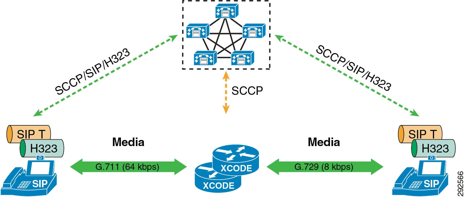
For dual stack MTP insertion, the bit rate is different on each connection but the bandwidth is different due to IP header overhead. Figure 13-50 illustrates the difference in bandwidth used for IPv4 and IPv6 networks with dual stack MTP insertion.
Figure 13-50 Bandwidth Differences for Dual Stack MTP Insertion
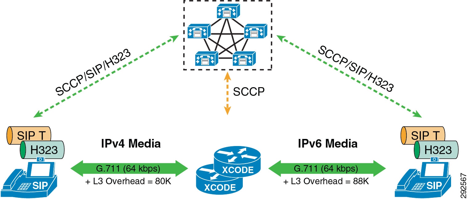
Enhanced Location CAC does not account for these differences in bandwidth between MTPs and transcoders. The service parameter Locations Media Resource Audio Bit Rate Policy determines whether the largest or smallest bandwidths should be used along the locations and links path. Lowest Bit Rate (default) or Highest Bit Rate can be used to manage these differences in bandwidth consumption.
Extension Mobility Cross Cluster with Enhanced Location CAC
Enhanced Location CAC supports designs using Extension Mobility Cross Cluster (EMCC). Unified CM provides the ability to perform Extension Mobility logins between clusters within an enterprise with a feature called Extension Mobility Cross Cluster (EMCC). For further information, see the section on Extension Mobility Cross Cluster (EMCC).
With Enhanced Location CAC in EMCC designs, the visiting cluster passes the location of the visiting phone to the home cluster. This allows the home cluster to associate the correct location to the visiting phone during registration. The following requirements must be met for Enhanced Location CAC to function in EMCC designs:
- Cisco Unified CM 10.0 or a later release required on both home and visiting clusters
- The visiting and home clusters must be in the same intercluster LBM replication network
Both Enhanced Location CAC and EMCC can be designed and deployed according to the guidelines in the product documentation and this SRND. There are no other requirements or any specific configuration aspects to employ.
Design Considerations for Call Admission Control
This section describes how to apply the call admission control mechanisms to various IP WAN topologies. With Unified CM Enhanced Location CAC network modeling support, Unified CM is no longer limited to supporting simple hub-and-spoke or MPLS topologies but, together with intercluster enhanced locations, can now support most any network topology in any Unified CM deployment model. Enhanced Location CAC is still a statically defined mechanism that does not query the network, and therefore the administrator still needs to provision Unified CM accordingly whenever network changes affect admission control. This is where a network-aware mechanism such as RSVP can fill that gap and provide support for dynamic changes in the network, such as when network failures occur and media streams take different paths in the network. This is often the case in designs with load-balanced dual or multi-homed WAN uplinks or unequally sized primary and backup WAN uplinks.
To learn how Enhanced Location CAC functions and how to design and deploy Enhanced location CAC, see the section on Unified CM Enhanced Location Call Admission Control.
In this section explores a few typical topologies and explains how Enhanced Location CAC can be designed to manage them.
Dual Data Center Design
Figure 13-51 illustrates a simple dual data center WAN network design where each remote site has a single WAN uplink to each data center. The data centers are interconnected by a high-speed WAN connection that is over-provisioned for data traffic.
Figure 13-51 Dual Data Center WAN Network
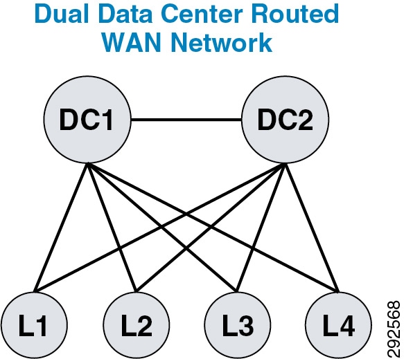
Typically these WAN uplinks from the remote sites to the data centers are load-balanced or in a primary/backup configuration, and there are limited ways for a static CAC mechanism to handle these scenarios. Although you could configure this multi-path topology in Enhanced Location CAC, only one path would be calculated as the effective path and would remain statically so until the weight metric was changed. A better way to support this type of network topology is to configure the two data centers as one data center or hub location in Enhanced Location CAC and configure a single link to each remote site location. Figure 13-52 illustrates an Enhanced Location (E-L) CAC locations and links overlay.
Figure 13-52 Enhanced Location CAC Topology Model for Dual Data Centers
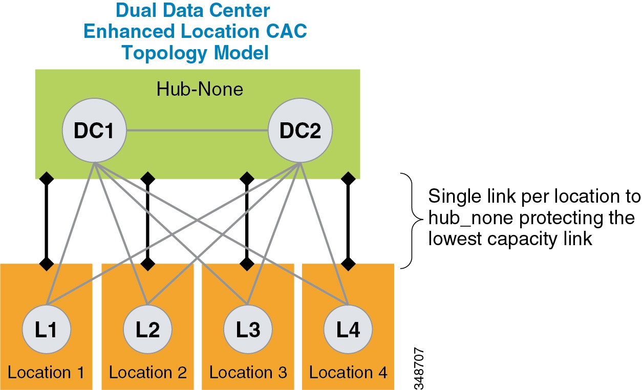
The following design recommendations for dual data centers with remote dual or more links to remote locations apply to both load-balanced and primary/backup WAN designs:
- A single location (Hub_None) represents both data centers.
- A single link between the remote locations and Hub_None protects the remote site uplinks from over-subscription during normal conditions or failure of the highest bandwidth capacity links.
- The capacity of link bandwidth allocation between the remote site and Hub_None should be equal to the lowest bandwidth capacity for the applicable Unified Communications media for a single link. For example, if each WAN uplink can support 2 Mbps of audio traffic marked EF, then the link audio bandwidth value should be no more than 2 Mbps to support a failure condition or equal-cost path routing.
MPLS Clouds
When designing for Multiprotocol Label Switching (MPLS) any-to-any connectivity type clouds in the Enhanced Location CAC network model, a single location can serve as the MPLS cloud. This location will not have any devices associated to it, but all of the sites that have uplinks to this cloud will have links configured to the location. In this way the MPLS cloud serves as a transit location for interconnecting multiple variable-sized bandwidth WAN uplinks to other remote locations. The illustrations in this section depict a number of different MPLS networks and their equivalent locations and links model.
In Figure 13-53, Hub_None represents the MPLS cloud serving as a transit location interconnecting the campus location where servers, endpoints, and devices are located, with remote locations where only endpoints and devices are located. Each link to Hub_None from the remote location may be sized according to the WAN uplink bandwidth allocated for audio, video, and immersive media.
Figure 13-53 Single MPLS Cloud
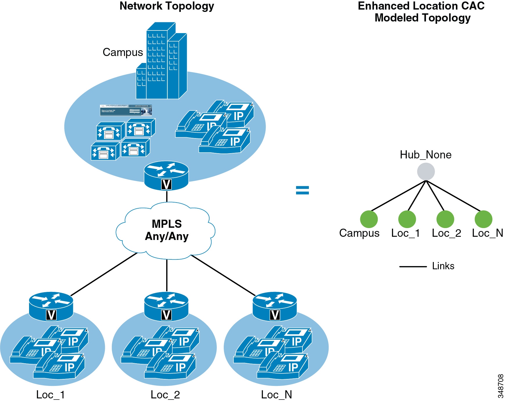
Figure 13-54 shows two MPLS clouds that serve as transit locations interconnecting the campus location where servers, endpoints, and devices are located, with remote locations where only endpoints and devices are located. The campus also connects to both clouds. Each link to the MPLS cloud from the remote location may be sized according to the WAN uplink bandwidth allocated for audio, vide, and immersive media. This design is typical in enterprises that span continents, with a separate MPLS cloud from different providers in each geographical location.
Figure 13-54 Separate MPLS Clouds

Figure 13-55 shows multiple MPLS clouds from different providers, where each site has one connection to each cloud and uses the MPLS clouds in either an equal-cost load-balanced manner or in a primary/backup scenario. In any case, this design is equivalent to the dual data center design where a single location represents both clouds and a single link represents the lowest capacity link of the two.
Figure 13-55 Remote Sites Connected to Dual MPLS Clouds

- The MPLS cloud should be configured as a location that does not contain any endpoints but is used as a hub to interconnect locations.
- The MPLS cloud serves as a transit location for interconnecting multiple variable-sized bandwidth WAN uplinks to other remote locations.
- Remote sites with connectivity to dual MPLS clouds should treat those connections as a single link and size to the lowest capacity of the links in order to avoid oversubscription during network failure conditions.
Call Admission Control Design Recommendations for Video Deployments
This section discusses Enhanced Location CAC and the design considerations and recommendations applicable to Quality of Service (QoS) when designing video deployments.
Admission control and QoS are complementary and in most cases co-dependent. Current Cisco product offerings such as audio and video endpoints, voice and video gateways, voice messaging, and conferencing all support native QoS packet marking based on IP Differentiated Services Code Point (IP DSCP). Note, however, that Jabber for Windows clients specifically do not follow the same native marking ability that other clients do, due to how the Windows operating systems requires the use of Group Policy Objects (GPO) using application, IP addresses, and UDP/TCP port ranges to mark traffic with DSCP. Group Policy Objects are very similar in function to network access lists in their ability to mark traffic.
QoS is critical to admission control because without it the network has no way of prioritizing the media to ensure that admitted traffic gets the network resources that it requires above that of non-admitted or other traffic classifications. In Unified CM's CallManager service parameters for QoS, there are five main QoS settings that are applicable to endpoint media classification and that also allow immersive and desktop classified endpoints (see the section on Enhanced Location CAC for TelePresence Immersive Video) to have different QoS markings for their media based on their video classification of immersive or desktop. Table 13-14 shows the five main DSCP settings along with their default settings and Per Hop Behavior (PHB) equivalents.
|
|
|
|
|---|---|---|
The DSCP for Audio Calls setting is used for any device that makes an audio-only call. The DSCP for Video Calls setting is used for the audio and video traffic of any device that is classified as "desktop." DSCP for TelePresence Calls is used for the audio and video traffic of any device that is classified as "immersive." The DSCP for Audio Portion of Video Calls and DSCP for Audio Portion of TelePresence Calls are currently applicable to a subset of video endpoints and differentiate only the audio portion of video calls dependent on the video call type based on classification. See the section on Trusted Endpoints, for more information.
As mentioned in the section on Enhanced Location CAC for TelePresence Immersive Video, Cisco Unified CM E-LCAC has the ability to perform admission control for TelePresence calls separately from other video calls. E-LCAC does this through a classification of endpoints and SIP trunks as "immersive" or "desktop." This classification gives Unified CM the ability to deduct bandwidth from a separate immersive bandwidth pool for those devices and trunks classified as immersive. By default LBM deducts ALL video, no matter the classification, from the video bandwidth pool (Unified CM's CallManager service parameter Use Video BandwidthPool for Immersive Video Calls set to True).
Also by default, all immersive classified endpoints have a DSCP set to CS4 (DSCP 32; DSCP for TelePresence Calls), while desktop endpoints have a DSCP set to AF41 (DSCP 34; DSCP for Video Calls). The default settings for QoS and E-LCAC differentiate DSCP but deduct all video from the same E-LCAC bandwidth pool. Figure 13-56 illustrates the QoS and E-LCAC bandwidth pool associations and defaults for immersive and desktop classified devices.
Figure 13-56 Default QoS Settings for CAC Bandwidth Pools
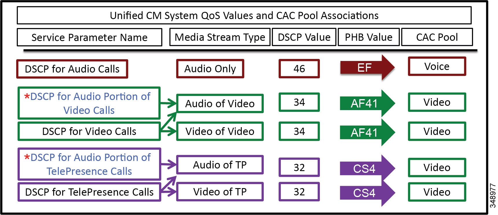
DSCP for TelePresence Calls is the immersive classification, and DSCP for Video Calls is the desktop classification.
Enhanced Location CAC Design Considerations and Recommendations
When designing Enhanced Location CAC for video, follow the design recommendations and considerations listed in this section.
Design Recommendations
The following design recommendations apply to video solutions that employ Enhanced Location CAC:
- If you are deploying Unified Communications video (desktop classification) and TelePresence video (immersive classification) where differentiation between desktop video and TelePresence video is a requirement, then ensure that the Unified CM service parameter Use Video Bandwidth Pool for Immersive Video Calls is set to false. This enables the immersive bandwidth pool for TelePresence calls.
- In Enhanced Location CAC, TelePresence endpoints can be managed in the same location as Unified Communications video endpoints. If TelePresence calls are not to be tracked through Enhanced Location CAC, then set the immersive location and links bandwidth pool to unlimited. This will ensure that CAC will not be performed on TelePresence or SIP trunks classified as immersive. If TelePresence calls are to be tracked through Enhanced Location CAC, then set immersive location and links bandwidth pool to a value according to the bit rate used and the number of calls to be allowed over the locations and link paths.
- Intercluster SIP trunks should be associated with the shadow location.
- Cisco Unified CM uses two different cluster-wide QoS service parameter to differentiate between the Differentiated Services Code Point (DSCP) settings of UC video endpoints and TelePresence endpoints. TelePresence endpoints use the DSCP for Telepresence calls QoS parameter while the Cisco UC video endpoints use the DSCP for video calls QoS service parameter.
- When marking video with the default QoS markings, the following recommendations apply:
–![]() For sites that deploy only UC endpoints and no TelePresence endpoints, ensure that the CS4 DSCP class is added to the AF41 QoS traffic class on inbound WAN QoS configurations to account for the inbound CS4 marked traffic, thus ensuring QoS treatment of CS4 marked media.
For sites that deploy only UC endpoints and no TelePresence endpoints, ensure that the CS4 DSCP class is added to the AF41 QoS traffic class on inbound WAN QoS configurations to account for the inbound CS4 marked traffic, thus ensuring QoS treatment of CS4 marked media.
–![]() For sites that deploy only UC TelePresence endpoints and no UC endpoints, ensure that the AF41 DSCP class is added to the CS4 QoS traffic class on inbound WAN QoS configurations to account for the inbound AF41 marked traffic, thus ensuring QoS treatment of AF41 marked media.
For sites that deploy only UC TelePresence endpoints and no UC endpoints, ensure that the AF41 DSCP class is added to the CS4 QoS traffic class on inbound WAN QoS configurations to account for the inbound AF41 marked traffic, thus ensuring QoS treatment of AF41 marked media.
Design Considerations
When deploying Enhanced Location CAC for immersive video calls, consider the effects of DSCP marking for both QoS classes, as the interoperable calls where an immersive classified endpoint is connected with a desktop classified endpoint are by default asymmetrically marked.
DSCP QoS Marking
The Differentiated Services Code Point (DSCP) QoS markings for TelePresence video interoperable calls are asymmetric, with AF41 used for the UC endpoints and CS4 for the TelePresence endpoints. AF41 and CS4 are default configurations in Unified CM, and changes to these defaults should align with the QoS configuration in the network infrastructure, as applicable. TelePresence endpoints mark video calls with a DSCP value of CS4, which is consistent with the default DSCP for Telepresence calls setting. UC endpoints mark calls with a DSCP value of AF41, which is consistent with the default DSCP for Video calls setting. Figure 13-57 illustrates the media marking and bandwidth accounting.
Figure 13-57 Bandwidth Deductions and Media Marking in a Multi-Site Deployment with Enhanced Location CAC
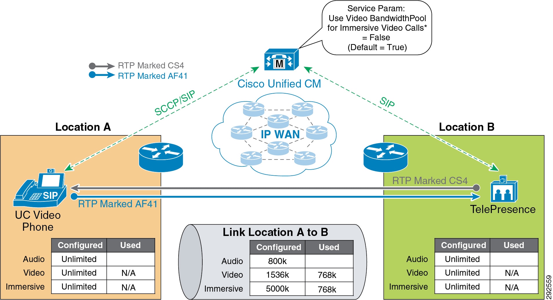
Bandwidth Accounting for TelePresence Video Interoperability Calls
Enhanced Location CAC for TelePresence-to-UC video interoperable calls deducts bandwidth from both the video and immersive locations and links bandwidth pools, as illustrated in Figure 13-57. This is by design to ensure that both types of QoS classified streams have the bandwidth required for media in both directions of the path between endpoints.
Enhanced Location CAC accounts for the bidirectional media of both AF41 and CS4 class traffic. In asymmetrically marked flows, however, the full allocated bit rate of the AF41 class is used in one direction but not the other. In the other direction, the full allocated bit rate is marked CS4. This does not represent additional bandwidth consumption but simply a difference in marking and queuing in the network for each QoS class. This manner of bandwidth accounting is required to protect each flow in each direction.
If TelePresence video (CS4) has been provisioned in the network paths separately from Unified Communications video (AF41) and TelePresence is largely scheduled and in environments where the scheduling of calls is controlled and the utilization of TelePresence is deterministic, then immersive video bandwidth for locations and links can be set to unlimited to avoid the double bandwidth CAC calculations. This ensures that TelePresence-to-TelePresence calls always go through unimpeded and will not be subject to admission control, while desktop video and TelePresence-to-desktop video calls will be subject to admission control and accounted for in the video bandwidth allocation.
For more information on the call flows for Enhanced Location CAC and TelePresence interoperable calls, see the section on Enhanced Location CAC for TelePresence Immersive Video.
Design Recommendations for Unified CM Session Management Edition Deployments with Enhanced Location CAC
Unified CM Session Management Edition (SME) is typically used for interconnecting multiple Unified CM clusters, third-party UC systems (IP- and TDM-based PBXs), PSTN connections, and centralized UC applications as well as for dial-plan and trunk aggregation. The following is a list of recommendations and design considerations to follow when deploying Unified CM SME with Enhanced Location CAC. For more information on Unified CM SME, see the chapter on Collaboration Deployment Models.
Recommendations and Design Considerations
- All leaf clusters that support Enhanced Location CAC should be enabled for intercluster Enhanced Location CAC with SME.
- SME can be used as a centralized bootstrap hub for the Enhanced Location CAC intercluster hub replication network. See LBM Hub Replication Network, for more information.
- All trunks to leaf clusters supporting Enhanced Location CAC should be SIP trunks placed in the shadow location to enable Enhanced Location CAC on the trunk between SME and the leaf clusters supporting Enhanced Location CAC.
- For TelePresence video interoperability, see the section on Call Admission Control Design Recommendations for Video Deployments.
- Connectivity from SME to any trunk or device other than a Unified CM that supports Enhanced Location CAC (some examples are third-party PBXs, gateways, Unified CM clusters that support only traditional Location CAC, voice messaging ports or trunks to conference bridges, Cisco Video Communications Server, and so forth) should be configured in a location other than a phantom or shadow location. The reason for this is that both phantom and shadow locations are non-terminating locations; that is, they relay information about locations and are effectively placeholders for user-defined locations on other clusters. Phantom locations are legacy locations that allow for the transmission of location information in versions of Unified CM that support only traditional Location CAC, but they are not supported with Unified CM Enhanced Location CAC. Shadow locations are special locations that enable trunks between Unified CM clusters that support Enhanced Location CAC to accomplish it end-to-end.
- SME can be used as a locations and link management cluster. See Figure 13-58 as an example of this.
- SME can support a maximum of 2,000 locations configured locally.
Figure 13-58 Unified CM SME as a Location and Link Management Cluster
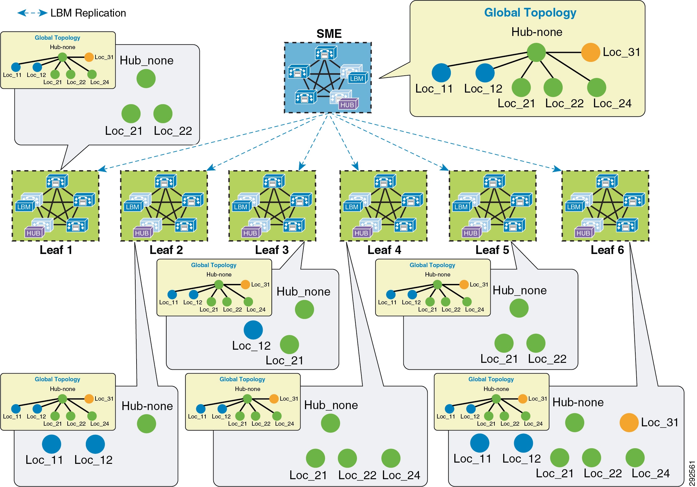
Figure 13-58 illustrates SME as a location and link management cluster. The entire location and link global topology is configured and managed in SME, and the leaf clusters configure locally only the locations that they require to associate with the end devices. When intercluster Enhanced Location CAC is enabled and locations and links are replicated, each leaf cluster will receive the global topology from SME and overlay this on their configured topology and use the global topology for call admission control. This simplifies configuration and location and link management across multiple clusters, and it diminishes the potential for misconfiguration across clusters. For more information and details on the design and deployment see the section on Location and Link Management Cluster.
Figure 13-59 illustrates an SME design where intercluster Enhanced Location CAC has been enabled on one or more leaf clusters (right) and where one or more leaf clusters are running a version of Unified CM that supports only traditional Location CAC (left). In this type of a deployment the locations managed by traditional Location CAC cannot be common or shared locations between clusters enabled for Enhanced Location CAC. Leaf 1 has been configured in a traditional hub and spoke, where devices are managed at various remote sites. SME and the other leaf clusters that are enabled for intercluster Enhanced Location CAC share a global topology, as illustrated in the E-L CAC Modeled Topology. Leaf1_Hub is a user-defined location in SME assigned to the SIP or H.323 intercluster trunk that represents the hub of the Leaf 1 topology. This allows SME to deduct bandwidth for calls to and from Leaf 1 up to the Leaf1_Hub. In this way SME and Leaf 2 manage the Enhanced Location CAC locations and links while Leaf 1 manages its remote locations with traditional Location CAC.
Figure 13-59 SME Design with Enhanced Location CAC and Traditional Location CAC in Leaf Clusters
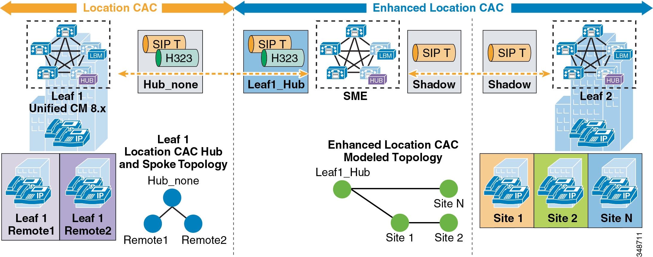
Design Recommendations for Cisco Expressway Deployments with Enhanced Location CAC
Cisco Expressway mobile and remote access capabilities provide registration of Internet-based devices to Unified CM without the use of a VPN, otherwise known as VPN-less enterprise access. This allows the endpoint or client application to register securely to Unified CM without the need for the entire operating system hosting the application to have access to the enterprise network. The following section lists the recommendations and design considerations for deploying mobile and remote access with Enhanced Location Call Admission Control (ELCAC). For more information on mobile and remote access, refer to the section on VPN-less Enterprise Access.
Recommendations and Design Considerations
In the Cisco Expressway VPN-less mobile and remote access solution, endpoints supporting the feature can register to Unified CM through a Cisco Expressway deployment without the use of a VPN. Cisco Expressway C and Expressway E servers are deployed, each with redundancy for high availability. Expressway E is placed in the DMZ between the firewall to the Internet (outside) and the firewall to the enterprise (inside), while Expressway C is placed inside the enterprise. Figure 13-60 illustrates this deployment. It also illustrates the following media flows:
1.![]() For Internet-based endpoints calling one another, the media is routed through Cisco Expressway E and Expressway C back out to the Internet, as is illustrated between endpoints B and C in Figure 13-60.
For Internet-based endpoints calling one another, the media is routed through Cisco Expressway E and Expressway C back out to the Internet, as is illustrated between endpoints B and C in Figure 13-60.
2.![]() For Internet-based endpoints calling internal endpoints, the media flows through the Expressway E and Expressway C, as is illustrated between endpoints A and C in Figure 13-60.
For Internet-based endpoints calling internal endpoints, the media flows through the Expressway E and Expressway C, as is illustrated between endpoints A and C in Figure 13-60.
Figure 13-60 Deployment of Cisco Expressway for VPN-less Access
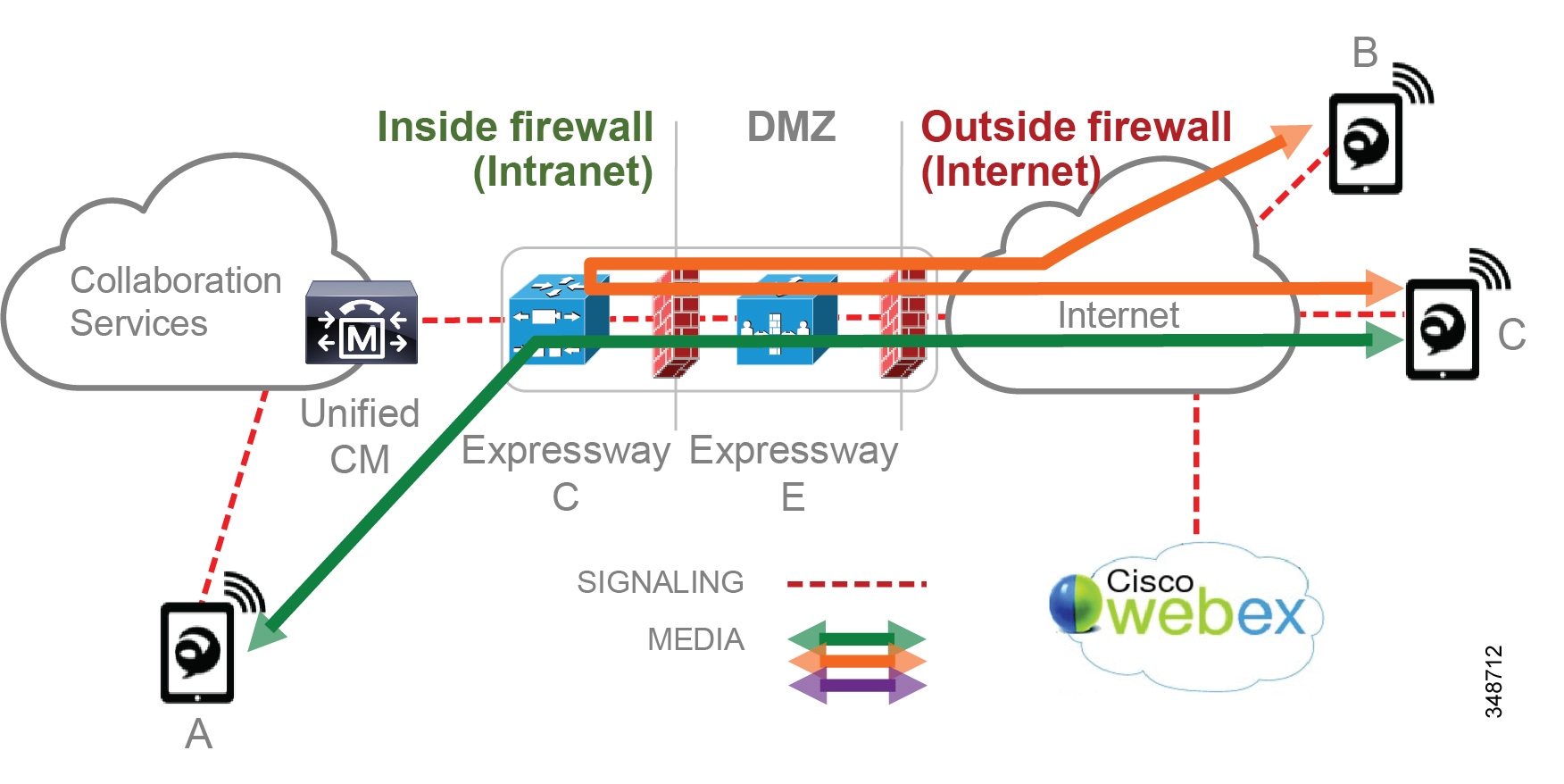
For multiple deployments of Cisco Expressway for VPN-less access in the same enterprise, with the Internet-based endpoints registered through one Expressway pair calling Internet-based endpoints registered through another Expressway pair, the media will be routed through the enterprise. This is illustrated in Figure 13-61 with a call between endpoint D and endpoint C, both registered from the Internet but through two different Expressway pairs. The media flow will be the same whether the endpoints are registered to the same Unified CM cluster or to different Unified CM clusters.
Figure 13-61 Media Flow for a Deployment of Multiple Cisco Expressway Pairs

Figure 13-62 illustrates an example configuration for locations and links that integrate bandwidth tracking for media flows that traverse the enterprise, while still allowing media flows over the Internet without admission control.
Figure 13-62 Locations and Links for Remote and Mobile Access
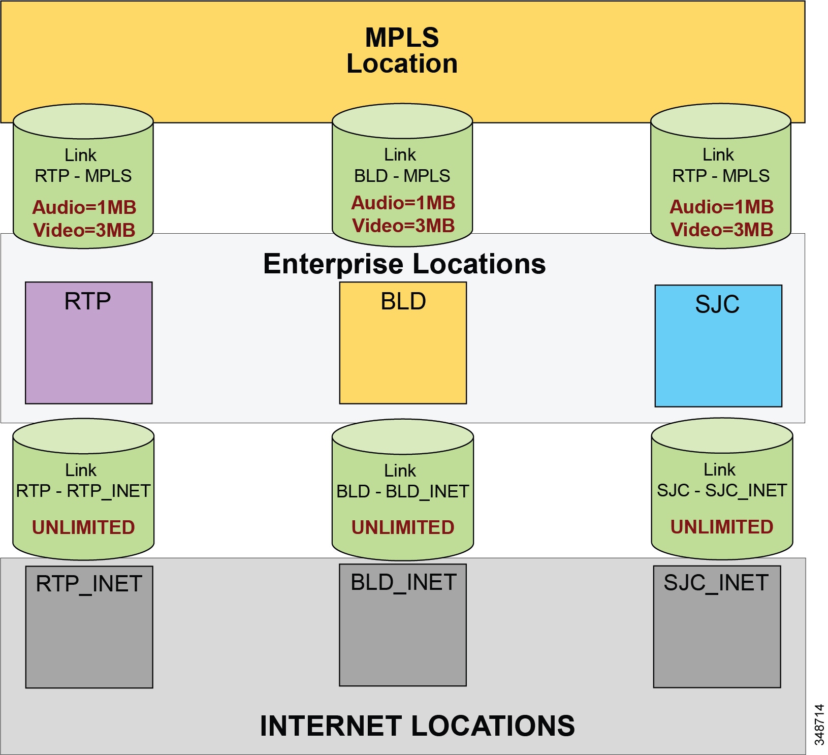
Figure 13-62 illustrates an example deployment of ELCAC consisting of three main sites: RTP, BLD, and SJC. These sites are all connected to an MPLS provider and thus each has a separate WAN connection to the MPLS cloud. Locations and links are created accordingly so that the enterprise locations are linked directly to a location called MPLS, with bandwidth links limited for audio and video calls mapping to the network topology. Devices are located in one of the three sites when in the enterprise and thus have a location associated to them. Each of these sites has a Cisco Expressway solution for VPN-less remote and mobile access for Internet-based endpoints registering to Unified CM. Three new locations are configured for the Internet-based devices, one for each Expressway solution site, named RTP_INET, BLD_INET, and SJC_INET. These three locations represent "Internet locations" because they are locations for devices registering from the Internet to Unified CM through an Expressway pair. These locations are not interconnected with direct links. This is because calls between Expressways are routed through the enterprise and thus flow through the MPLS cloud. These Internet locations, instead, have a link to their associated enterprise location. For example, RTP_INET has a link to RTP, BLD_INET has a link to BLD, and so forth. These links between the Internet locations and the enterprise locations should be set to unlimited bandwidth.
As mentioned, Enhanced Location CAC for Cisco Expressway deployments requires the use of a feature in Unified CM called Device Mobility. (For details about this feature, see the section on Device Mobility.) Enabling device mobility on the endpoints allows Unified CM to know when the device is registered through the Cisco Expressway or when it is registered from within the enterprise. Device mobility also enables Unified CM to provide admission control for the device as it roams between the enterprise and the Internet. Device mobility is able to do this by knowing that, when the endpoints register to Unified CM with the IP address of Expressway C, Unified CM will associate the applicable Internet location. However, when the endpoint is registered with any other IP address, Unified CM will use the enterprise location that is configured directly on the device (or from the device pool directly configured on the device). It is important to note that device mobility does not have to be deployed across the entire enterprise for this function to work. Configuration of Device Mobility in Unified CM is required only for the Expressway IP addresses, and the feature is enabled only on the devices that require the function (that is to say, those devices registering through the Internet). Figure 13-63 illustrates an overview of the device mobility configuration. Although this is a minimum configuration requirement for Device Mobility for ELCAC to function for internet-based devices, Device Mobility can be configured to support mobility for these same endpoints within the enterprise. (See the section on Device Mobility, for more information.)
Figure 13-63 Device Mobility Configuration and Location Association
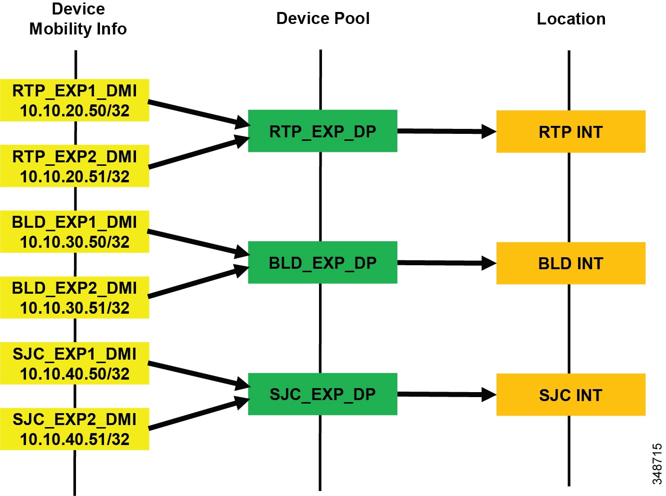
Figure 13-63 shows a simplified version of device mobility for the example deployment of ELCAC as described in Figure 13-62. The IP addresses of the Expressway C servers are configured in the device mobility information. In this example there is a redundant pair of Expressway C servers for each of the three sites, RTP, BLD, and SJC. RTP_EXP1_DMI and RTP_EXP2_DMI are configured respectively with the server IP addresses of the RTP Expressway C servers. These two are associated to a new device pool called RTP_EXP_DP, which has the location RTP_INET configured on it. Each site is configured similarly. With this configuration, when any device enabled for device mobility registers to Unified CM with the IP Address that corresponds to the device mobility information in RTP_EXP1_DMI or RTP_EXP2_DMI, it will be associated with the RTP_EXP_DP device pool and thus with the RTP_INET location.
With the above configuration, when an Internet-based device registers through the Expressway to Unified CM, it will register with the IP address of Expressway C. Unified CM then uses the IP address configured in the device mobility information and associates the device pool and thus the Internet location associated to this device pool. This process is illustrated in Figure 13-64.
Figure 13-64 Association of Device Pool and Location Based on Expressway IP Address

In Figure 13-64 the client registers with Unified CM through the Expressway in RTP. Because the signaling is translated at the Expressway C in RTP, the device registers with the IP address of the Expressway C. The device pool RTP_EXP_DP is associated to the device based on this IP address. The RTP_EXP_DP pool is configured with the RTP_INET location, and therefore that location is associated to the device. Thus, when devices register to the Expressway, they get the correct location association through device mobility. When the endpoint relocates to the enterprise, it will return to its static location configuration. Also, if the endpoint relocates to another Expressway in SJC, for example, it will get the correct location association through device mobility.
Design and Deployment Best Practices for Cisco Expressway VPN-less Access with Enhanced Location CAC
- Each site with Internet access, where a Cisco Expressway solution resides, requires an Internet location and an enterprise location. Each Cisco Expressway deployment requires these location pairs. The enterprise location is associated to devices when they are in the enterprise (see locations RTP, BLD, and SJC in Figure 13-62). The Internet location is associated to the endpoints through the Device Mobility feature when the endpoints are registering from the Internet (see locations RTP_INET, BLD_INET, and SJC_INET in Figure 13-62). For example, in Figure 13-62, RTP and RTP_INET form a location pair for the physical site RTP.
- Enterprise locations are configured according to applicable enterprise ELCAC design.
- Internet locations will always have a single link to the enterprise location that they are paired with. For example, in Figure 13-62, RTP and RTP_INET form an enterprise location and internet location pair.
- Links from Internet locations to enterprise locations are set to unlimited bandwidth. Unlimited bandwidth between these location pairs ensures that bandwidth is not counted for calls from the Internet location to the local enterprise location, and vice versa (for example, calls from RTP to RTP_INET in Figure 13-62).
- In a Cisco Expressway solution where more than one Cisco Expressway site is deployed, and requiring multiple Internet locations, ensure that Internet locations do not have direct links between one another. Direct links between Internet locations will create multiple paths in ELCAC, and for that reason they are not recommended.
- When configuring DSCP on Cisco Expressway, ensure that it is consistent with your endpoint marking policy. Starting with Cisco Expressway Release 8.9, DSCP can be configured separately for signaling, audio, video, and XMPP. Thus, it is possible to configure signaling as CS3 (24), audio as EF (46), video as AF41 (32), and XMPP as CS3 (24), and the Expressway-C will appropriately mark the media and signaling traffic coming from the Internet into the Enterprise. When you upgrade an Expressway server from a release prior to 8.9, the single configured DSCP value used in the earlier release will be populated across all 4 values in the new Expressway release.
Bandwidth Management Design Examples
This section covers design examples and explores all aspects discussed in this chapter – identification and classification, WAN queuing and scheduling, provisioning and resource control, and bandwidth allocation guidelines – with details for each site in the examples.
Example Enterprise #1
Example Enterprise #1 is a large enterprise with users across a large geographic area, with a data center (DC) at the headquarters site as well as multiple large, small, and micro-sized branches with roughly 500, 50, 15, and 5 users in each branch type, respectively. To simplify the illustration of the network, these categories of sites (HQ, large, small and micro) are used as a template to size bandwidth considerations for each site that has a similar user base and endpoint density. Figure 13-65 illustrates each type of site. The enterprise has deployed Jabber with video to ensure that users have access to a video terminal for conferencing. The TelePresence video conferencing resources are located in the DC at HQ. IP phones are for voice-only communications; video endpoints are Jabber clients, Collaboration desktop endpoints (DX Series), and room endpoints (MX, Profile, and SX Series); and the HQ and large sites have immersive TelePresence units such as the IX Series.
Figure 13-65 Example Enterprise #1
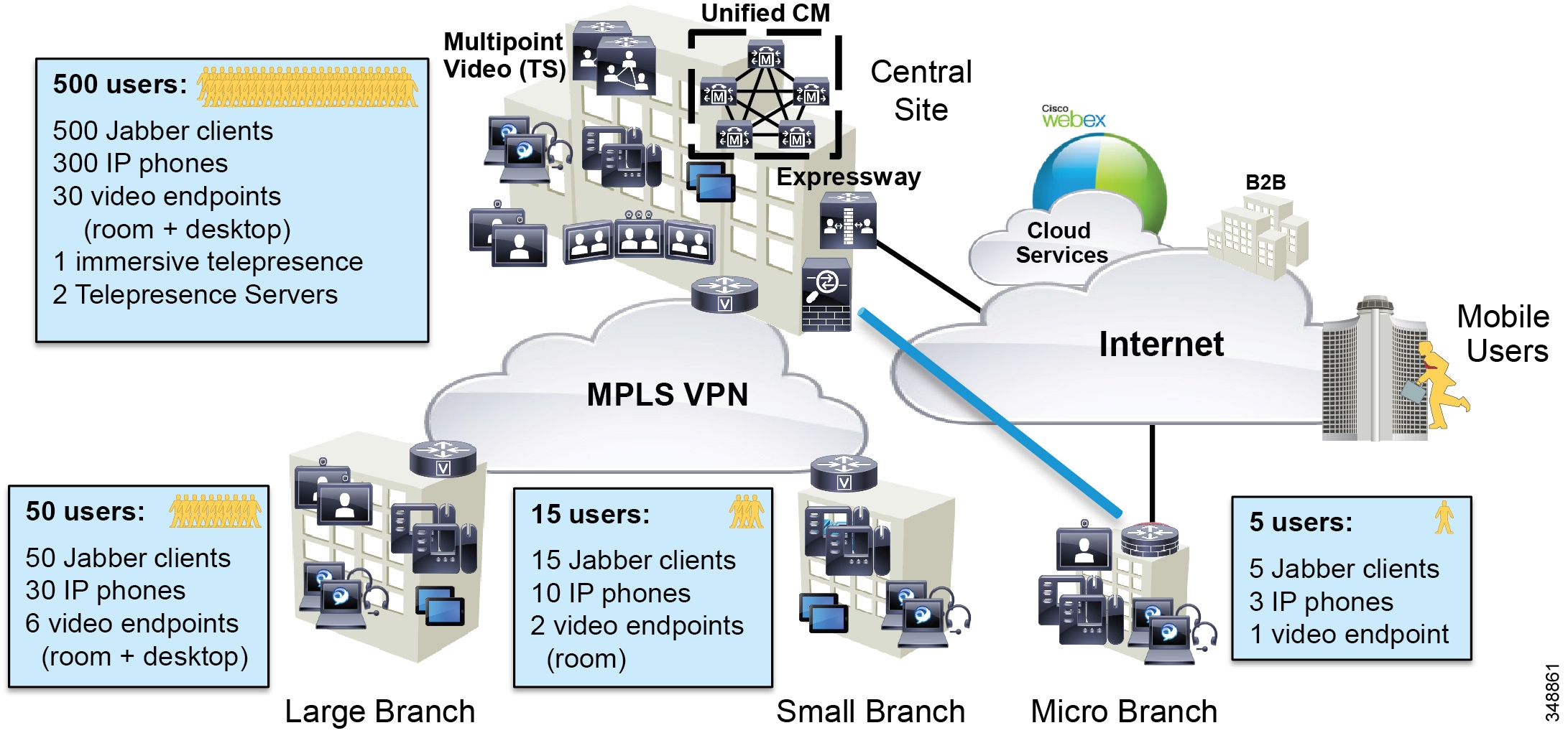
The IT department is tasked with determining the bandwidth requirements for the WAN edge for each type of site in Example Enterprise #1. The following sections list the requirements and illustrate a methodology for applying QoS and for determining bandwidth and queuing requirements as well as admission control requirements.
Identification and Classification
In this phase the QoS requirements are established across the enterprise.
Untrusted Endpoints (Jabber)
Jabber endpoints are untrusted and sit in the data VLAN. Specific UDP port ranges will be used to re-mark signaling and media at the access layer switch. In this case Unified CM is configured with a SIP Profile specifically for all Jabber clients to use the Common Media and Signaling Port Range of 3000 to 4999. This sets all Jabber endpoints to use a source UDP port of 3000 to 3999 for audio streams and 4000 to 4999 for video streams. The default SIP port of 5060 is used for SIP signaling (configured in the SIP Security Profile). This is illustrated in Figure 13-66.
Figure 13-66 Untrusted (Jabber) Endpoint QoS

The administrator creates an ACL for the access switches for the data VLAN to re-mark UDP ports to the following DSCP values:
- Audio: UDP Ports 3000 to 3999 marked to AF41
- Video: UDP Ports 4000 to 4999 marked to AF42
- Signaling: TCP Port 5060 marked to CS3
Jabber classification summary:
- Audio streams of all Jabber calls (voice-only and video calls) are marked AF41.
- Video streams of Jabber video calls are marked AF42.
For the Jabber endpoints, we also recommend changing the default QoS values in the Jabber SIP profile. This is to ensure that, if for any reason the QoS of a Jabber client is trusted via a wireless route or any other wired route, the correct trusted values will be coherent between the trusted QoS and the QoS that is re-marked with the ACLs. Therefore, the QoS parameters in the SIP Profile for Jabber clients need to be set as shown in Table 13-15 .
|
|
|
|
|---|---|---|
The configuration settings in Table 13-15 ensure that video of Jabber clients will be set to AF42 if for any reason the traffic follows a trusted network path and is not re-marked via UDP port ranges as in the untrusted network path. The DSCP for Audio Portion of Video Calls is left at the default setting of AF41. This is simply to ensure a consistent configuration across Jabber endpoints, whether trusted or re-marked via the network using UDP port ranges.
Trusted Endpoints
For the trusted endpoints, Cisco Discovery Protocol (CDP) is used and the QoS of the IP phones and video endpoints is trusted using the conditional trust mechanism configured at the access switch. The configuration uses the Unified CM default system settings of audio for voice-only calls as EF, audio and video for video calls as AF41, audio and video for TelePresence as CS4, and signaling as CS3. Therefore, the administrator must change the QoS defaults in Unified CM for the trusted endpoints with a SIP Profile to ensure that the QoS of the TelePresence endpoints is adjusted accordingly.
Figure 13-67 illustrates the conditional trust (CDP based) and packet marking at the access switch.
Figure 13-67 Trusted Endpoint QoS
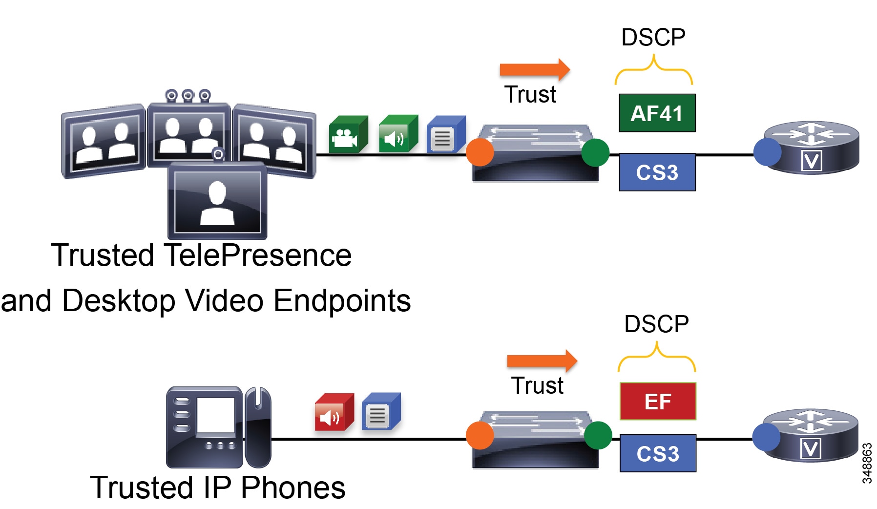
The administrator configures all access switches with a conditional QoS trust for IP phones and video and TelePresence endpoints, classified as follows:
The administrator must also change the QoS defaults in Unified CM for the trusted endpoints with a SIP Profile using the values in Table 13-16 .
|
|
|
|
|---|---|---|
On ingress at the WAN edge, it is expected that the packets arriving with a specific DSCP value have been trusted at the access layer or re-marked accordingly if they were not trusted at the access switch. As a failsafe practice, on ingress it is important to re-mark any untrusted traffic at the WAN edge that could not be re-marked at the access layer. While QoS is important in the LAN, it is paramount in the WAN; and as routers assume a trust on ingress traffic, it is important to configure the correct QoS policy that aligns with the business requirements and user experience. The WAN edge re-marking is always done on the ingress interface into the router, while the queuing and scheduling is done on the egress interface. The following example walks through the WAN ingress QoS policy as well as the egress queuing policy. Figure 13-68 illustrates the configuration and the re-marking process.
In Figure 13-68 the packets from both the trusted and untrusted areas of the network are identified and classified with the appropriate DSCP marking via the trust methods discussed or via a simple ACL matching on UDP port ranges. Keep in mind that this ACL could also match more granularly on IP addresses or some other attributes that would further limit the scope of the marking.
Figure 13-68 Example Router Ingress QoS Policy Process – 1
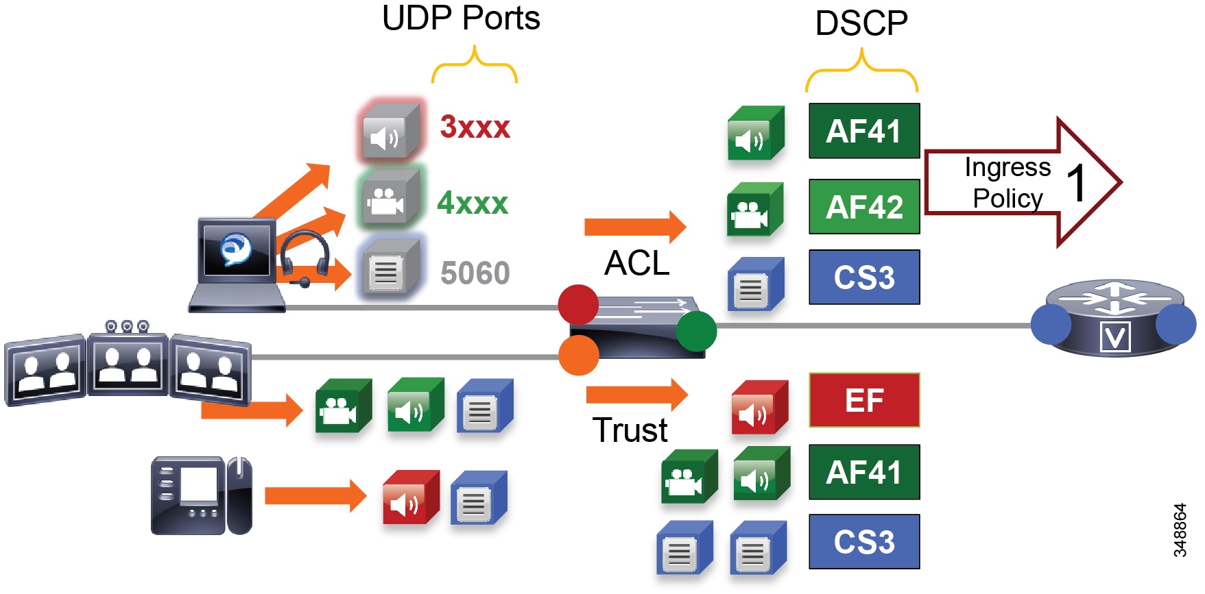
Figure 13-69 through Figure 13-73 illustrate the ingress QoS policy matching criteria and DSCP re-marking. The process involves the following steps shown in the figures:
1.![]() Packets arrive into the router ingress interface, which is configured with an input service policy (Figure 13-69).
Packets arrive into the router ingress interface, which is configured with an input service policy (Figure 13-69).
2.![]() The policy-map is configured with 4 classes of traffic setting the appropriate DSCP: Voice setting a DSCP of EF, Prioritized-Video (includes Jabber audio) setting a DSCP of AF41, Jabber-Video setting a DSCP of AF42, and Signaling setting a DSCP of CS3 (Figure 13-69).
The policy-map is configured with 4 classes of traffic setting the appropriate DSCP: Voice setting a DSCP of EF, Prioritized-Video (includes Jabber audio) setting a DSCP of AF41, Jabber-Video setting a DSCP of AF42, and Signaling setting a DSCP of CS3 (Figure 13-69).
3.![]() Each one of these classes matches a class-map of the same name configured with match-any criteria and a DSCP match as well as an ACL match (Figure 13-69). This match-any criteria means that the process will start top-down, and the first matching criteria will be executed and thus set the DSCP according to each class in the policy-map statements. Another option is match-all, which would require all criteria to be matched and thus would match DSCP and ACL. This, however, would not provide the intended functionality of re-marking either marked or unmarked traffic.
Each one of these classes matches a class-map of the same name configured with match-any criteria and a DSCP match as well as an ACL match (Figure 13-69). This match-any criteria means that the process will start top-down, and the first matching criteria will be executed and thus set the DSCP according to each class in the policy-map statements. Another option is match-all, which would require all criteria to be matched and thus would match DSCP and ACL. This, however, would not provide the intended functionality of re-marking either marked or unmarked traffic.
Figure 13-69 Example Router Ingress QoS Policy Process – 2

4.![]() The first match statement in the class-map is match dscp, If the traffic matches the DSCP, then DSCP is set again to the same value that was matched, as is configured in the policy-map statements (Figure 13-70).
The first match statement in the class-map is match dscp, If the traffic matches the DSCP, then DSCP is set again to the same value that was matched, as is configured in the policy-map statements (Figure 13-70).
Figure 13-70 Example Router Ingress QoS Policy Process – 3

5.![]() If DSCP was not matched, then the next line in the class-map statement is parsed, which is the ACL that matches the UDP ports set in Unified CM for the Jabber clients (see Identification and Classification). When the ACL criteria (protocol and port range) are met, then the traffic is set as is configured in the corresponding policy-map statements (Figure 13-71).
If DSCP was not matched, then the next line in the class-map statement is parsed, which is the ACL that matches the UDP ports set in Unified CM for the Jabber clients (see Identification and Classification). When the ACL criteria (protocol and port range) are met, then the traffic is set as is configured in the corresponding policy-map statements (Figure 13-71).
Figure 13-71 Example Router Ingress QoS Policy Process – 4


Note![]() This is an example QoS ingress marking policy based on the Modular QoS CLI (MQC). Refer to your specific router configuration guide for information on how to achieve a similar policy on a Cisco router supporting MQC and for any updated commands.
This is an example QoS ingress marking policy based on the Modular QoS CLI (MQC). Refer to your specific router configuration guide for information on how to achieve a similar policy on a Cisco router supporting MQC and for any updated commands.
6.![]() The traffic goes to an outbound interface to be queued and scheduled by an output service policy that has 3 queues created: a Priority Queue called VOICE, a CBWFQ called VIDEO, and another CBWFQ called SIGNALING (Figure 13-72). This highlights the fact that this egress queuing policy is based only on DSCP as network marking occurring at the access switch and/or on ingress into the WAN router ingress interface. This is an example simply to illustrate the matching criteria and queues, and it does yet not contain the WRED functionality (covered in the next subsection). For more information on WRED, see the next section on WAN Queuing and Scheduling.
The traffic goes to an outbound interface to be queued and scheduled by an output service policy that has 3 queues created: a Priority Queue called VOICE, a CBWFQ called VIDEO, and another CBWFQ called SIGNALING (Figure 13-72). This highlights the fact that this egress queuing policy is based only on DSCP as network marking occurring at the access switch and/or on ingress into the WAN router ingress interface. This is an example simply to illustrate the matching criteria and queues, and it does yet not contain the WRED functionality (covered in the next subsection). For more information on WRED, see the next section on WAN Queuing and Scheduling.
Figure 13-72 Example Router Egress Queuing Policy Process – 1

7.![]() The traffic is matched against the class-map match statements, and all traffic marked EF goes to the VOICE PQ, AF41 and AF42 traffic goes to the VIDEO CBWFQ, and CS3 traffic goes to the SIGNALING CBWFQ (Figure 13-73).
The traffic is matched against the class-map match statements, and all traffic marked EF goes to the VOICE PQ, AF41 and AF42 traffic goes to the VIDEO CBWFQ, and CS3 traffic goes to the SIGNALING CBWFQ (Figure 13-73).
Figure 13-73 Example Router Egress Queuing Policy Process – 2


Note![]() This is an example egress queuing policy based on the Cisco Common Classification Policy Language (C3PL). Refer to your specific router configuration guide for information on how to achieve a similar policy on a Cisco router supporting C3PL and for any updated commands.
This is an example egress queuing policy based on the Cisco Common Classification Policy Language (C3PL). Refer to your specific router configuration guide for information on how to achieve a similar policy on a Cisco router supporting C3PL and for any updated commands.
WAN Queuing and Scheduling
This section discusses the interface queuing. Figure 13-74 illustrates the voice PQ, the video CBWFQ, and the WRED thresholds used for the CBWFQ:
- Voice-only calls from trusted endpoints (EF) are mapped to the PQ.
- Prioritized video calls and Jabber share the same CBWFQ:
–![]() AF41 for audio and video streams of video calls from trusted endpoints
AF41 for audio and video streams of video calls from trusted endpoints
–![]() AF41 for audio streams of all calls from Jabber clients
AF41 for audio streams of all calls from Jabber clients
–![]() AF42 for video streams of video calls from Jabber clients
AF42 for video streams of video calls from Jabber clients
–![]() Minimum and maximum thresholds for AF42:
Minimum and maximum thresholds for AF42:
Approximately 10% to 30% of queue limit
–![]() Minimum and maximum thresholds for AF41:
Minimum and maximum thresholds for AF41:
Approximately 45% to 100% of queue limit
Figure 13-74 Queuing and Scheduling Collaboration Media
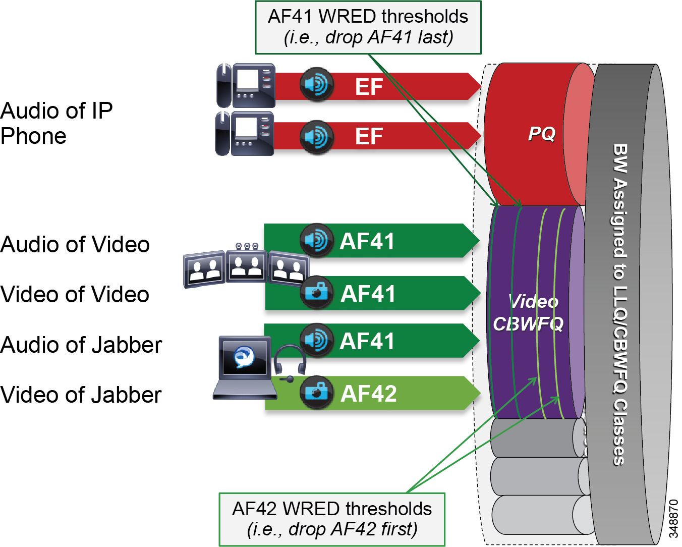
Weighted Random Early Detection (WRED) minimum and maximum thresholds are also configured in the Video CBWFQ. To illustrate how the WRED thresholds are configured, assume that the interface had been configured with a queue depth of 256 packets. Then following the guidelines listed above, the WRED minimum and maximum thresholds for AF42 and AF41 would be configured as illustrated in Figure 13-75.
Figure 13-75 Example of Video CBWFQ with WRED Thresholds
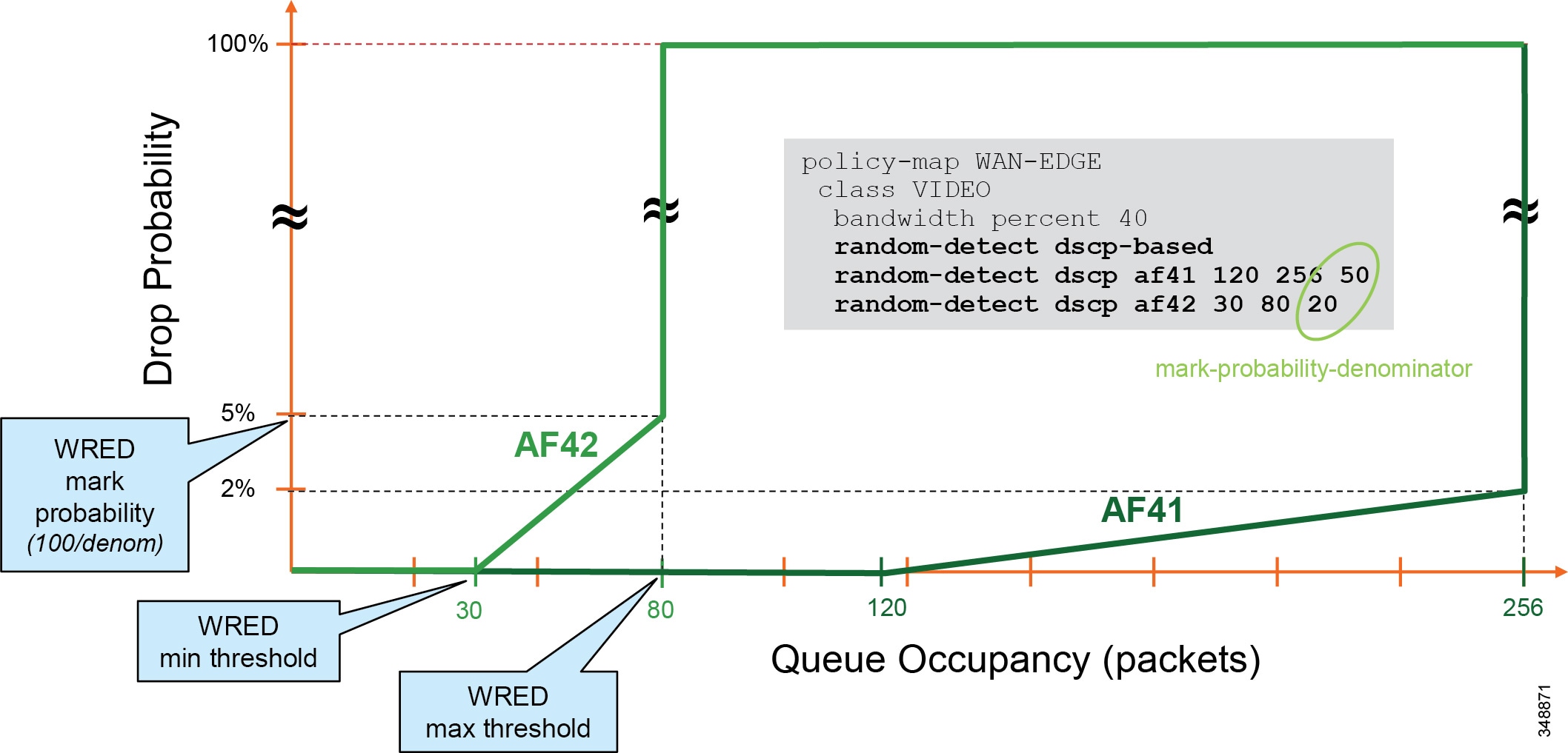
Provisioning and Admission Control
This section addresses admission control and provisioning bandwidth to the queues for each site type.
As mentioned previously, admission control is not used in this example case to manage the video bandwidth but instead to manage the audio traffic to ensure that the PQ is not over-subscribed. This is for voice-only calls.
Figure 13-76 illustrates the various call flows, their corresponding audio and video streams, and the queues to which they are directed.
Figure 13-76 Provisioning and Admission Control
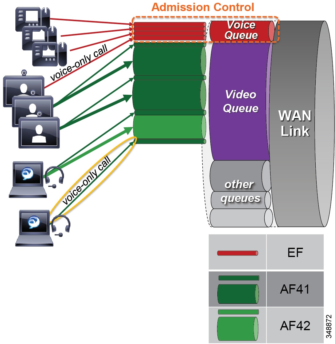
The example in Figure 13-76 uses the following configuration:
- Priority queue is provisioned for voice calls from trusted endpoints and is protected by admission control (ELCAC voice bandwidth pool).
- Video queue is over-provisioned for room-based video systems:
–![]() Ratios are applied to bandwidth usage for desktop video endpoints.
Ratios are applied to bandwidth usage for desktop video endpoints.
–![]() Jabber video calls can use any bandwidth unused by video room systems.
Jabber video calls can use any bandwidth unused by video room systems.
–![]() During congestion, video streams of Jabber calls are subject to WRED drops and dynamically reduce video bit rate.
During congestion, video streams of Jabber calls are subject to WRED drops and dynamically reduce video bit rate.
Bandwidth Allocation Guidelines
The bandwidth allocations in Figure 13-77 are guidelines based solely on this Example Enterprise #1. They provide some guidance on percentages of available bandwidth for various common classes of Collaboration traffic. It is important to understand that bandwidth provisioning is highly dependent on utilization, and this will be different for each deployment and the user base being served at each site. The following examples provide a process to utilize for bandwidth provisioning. After provisioning the bandwidth, monitoring it and readjusting it are always necessary to ensure the best possible bandwidth provisioning and allocation necessary for an optimal user experience.
Figure 13-77 Bandwidth Allocation Guidelines
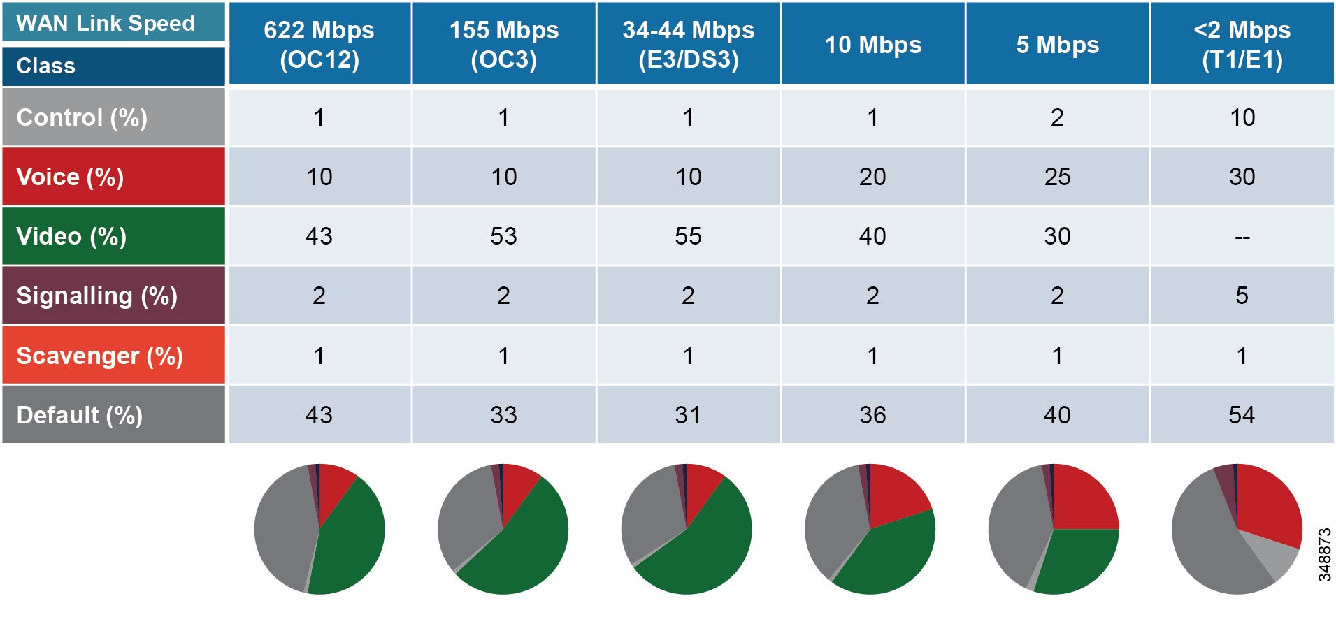
The following sections cover each site (Central, Large Branch, Small Branch, Micro Branch) and the link bandwidth provisioned for each class based on the number of users and available bandwidth for each class. Keep in mind that these values are based on bandwidth calculated for Layer 3 and above. Therefore, they do not include the Layer 2 overhead, which is dependent on the link type (Ethernet, Frame-relay, MPLS, and so forth). See the chapter on Network Infrastructure, for more information on Layer 2 overhead.
Central Site Link (100 Mbps) Bandwidth Calculation
As illustrated in Figure 13-78, the Central Site has the following bandwidth requirements:
–![]() Immersive endpoint: 2 Mbps ∗ 1 call = 2 Mbps
Immersive endpoint: 2 Mbps ∗ 1 call = 2 Mbps
–![]() Video endpoints: 1.2 Mbps ∗ 30 calls ∗ 0.2 = 7.2 Mbps
Video endpoints: 1.2 Mbps ∗ 30 calls ∗ 0.2 = 7.2 Mbps
–![]() TelePresence Servers: 1.5 Mbps ∗ 40 calls ∗ 0.5 = 30 Mbps
TelePresence Servers: 1.5 Mbps ∗ 40 calls ∗ 0.5 = 30 Mbps
–![]() 55 Mbps – (2 Mbps + 7.2 Mbps + 30 Mbps) = 15.8 Mbps for Jabber media
55 Mbps – (2 Mbps + 7.2 Mbps + 30 Mbps) = 15.8 Mbps for Jabber media
18 Jabber video calls @ 576p, or 50 @ 288p
Immersive endpoints are sized for the busy hour. One endpoint is expected to be in a call across the WAN. This would be for a point-to-point call, since any conference call would terminate locally at the TelePresence server. It is important to take into account the worst-case scenario for the busy hour.
Video endpoints are sized for 20% WAN utilization (∗0.2). A possible total of 30 calls at 1.2 Mbps is based on the number of endpoints. But assuming only 20% WAN utilization in active calls over the WAN, compared to active local calls, gives the WAN utilization rate of above 7.2 Mbps.
TelePresence Servers are sized at an average bit rate of 1.5 Mbps to account for the average of various endpoint resolutions from remote sites. The TelePresence Server would then be able to support up to 40 calls total (local and remote), and this is multiplied by 50% (0.5) to account for the possibility of half of the TelePresence calls going over the WAN while the other half might be serving local endpoints.
In addition there is 15.8 Mbps for Jabber calls, which could be 18 calls at 576p, or 50 calls at 288p, or variations thereof. This gives an idea of what the Jabber video calls have available for bandwidth. When more Jabber video calls occur past the 15.8 Mbps, packet loss will occur and will force all Jabber clients to adjust their bit rates down. This can be either a very subtle process with no visible user experience implications if the loss rate is low as new calls are added, or it can be very disruptive to the Jabber video if there is an immediate and sudden loss of packets. The expected packet loss rate as new video calls are added is helpful in determining the level of disruption in the user experience for this opportunistic class of video.
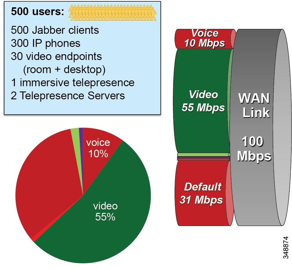
Large Branch Link (34 Mbps) Bandwidth Calculation
As illustrated in Figure 13-79, the Large Branch site has the following bandwidth requirements:
–![]() Video endpoints: 1.2 Mbps ∗ 6 calls = 7.2 Mbps
Video endpoints: 1.2 Mbps ∗ 6 calls = 7.2 Mbps
–![]() 18.7 Mbps – 7.2 Mbps = 11.5 Mbps for Jabber media
18.7 Mbps – 7.2 Mbps = 11.5 Mbps for Jabber media
13 Jabber video calls @ 576p, or 36 @ 288p
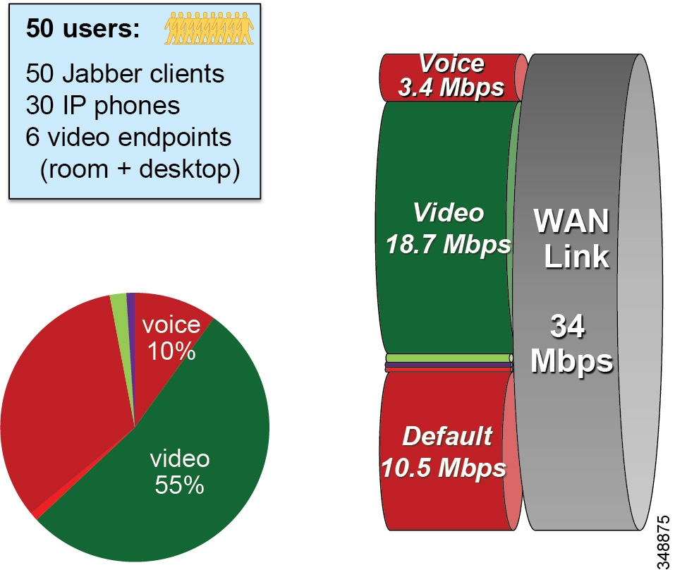
Small Branch Link (10 Mbps) Bandwidth Calculation
As illustrated in Figure 13-80, the Small Branch site has the following bandwidth requirements:
–![]() Video endpoints: 1.2 Mbps * 2 calls = 2.4 Mbps
Video endpoints: 1.2 Mbps * 2 calls = 2.4 Mbps
–![]() 4 Mbps – 2.4 Mbps = 1.6 Mbps for Jabber media
4 Mbps – 2.4 Mbps = 1.6 Mbps for Jabber media
2 Jabber video calls @ 576p, or 5 @ 288p
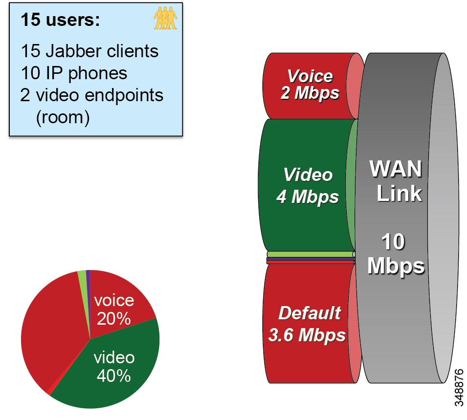
Micro Branch Broadband Internet Connectivity (5 Mbps) Bandwidth Calculation
As illustrated in Figure 13-81, the Micro Branch site has the following bandwidth requirements:
- Broadband Internet connectivity + DMVPN to central site
- Configure interface of VPN router to match broadband uplink speed
- Enable QoS on VPN router to prevent bufferbloat from TCP flows
- Asymmetric download/upload broadband: consider limiting transmit bit rate on video endpoint
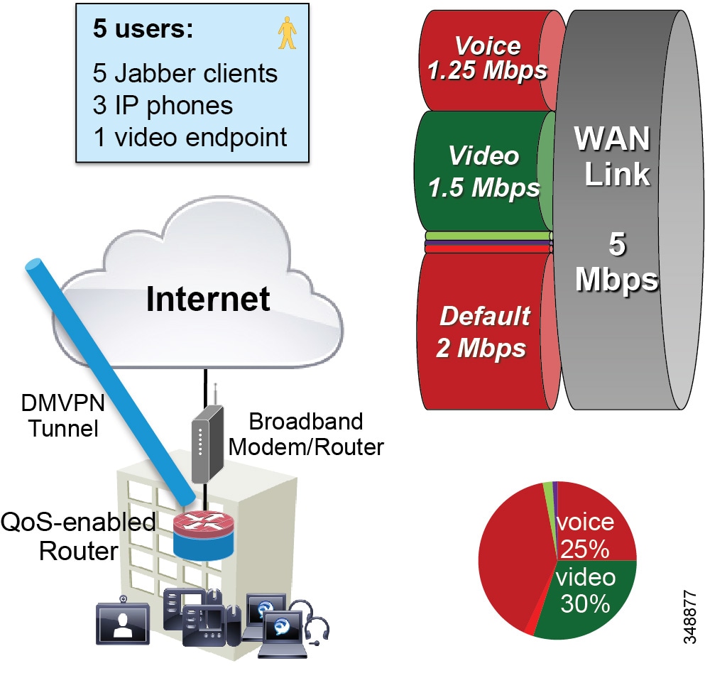
Large Branch with Constrained WAN Link (Enhanced Locations CAC Enabled for Video)
In specific branch sites with lower-speed WAN links, over-provisioning the video queue is not feasible (see Figure 13-82). ELCAC can be applied to these Location links for video to ensure that video calls do not over-subscribe the link bandwidth. This template requires using site-specific region configuration to limit maximum bandwidth used by video endpoints and Jabber clients. Also keep in mind that device mobility is required if Jabber users roam across sites.

Note![]() Bandwidth for voice-only Jabber calls is subtracted from "voice" ELCAC, but it impacts the video queue (since it is marked AF41). Adjust the delta between video ELCAC bandwidth and video queue size.
Bandwidth for voice-only Jabber calls is subtracted from "voice" ELCAC, but it impacts the video queue (since it is marked AF41). Adjust the delta between video ELCAC bandwidth and video queue size.
Figure 13-82 Large Branch with Constrained WAN Link (Enhanced Locations CAC Enabled for Video)
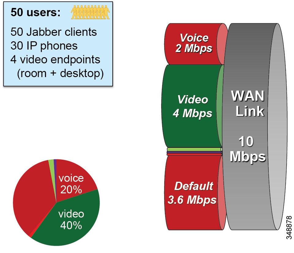
As illustrated in Figure 13-82, a Large Branch site with a constrained WAN link (10 Mbps) has the following bandwidth requirements:
–![]() Possible usage: 2 calls @ 576p (768 kbps) + 5 calls @ 288p (320 kbps) = 3,136 kbps
Possible usage: 2 calls @ 576p (768 kbps) + 5 calls @ 288p (320 kbps) = 3,136 kbps
–![]() Unified CM Location link bandwidth for video calls: 3.2 Mbps (L3 bandwidth)
Unified CM Location link bandwidth for video calls: 3.2 Mbps (L3 bandwidth)
–![]() Leaves room for L2 overhead, burstiness, and Jabber audio-only calls marked AF41
Leaves room for L2 overhead, burstiness, and Jabber audio-only calls marked AF41
Example Enterprise #2
Example Enterprise #2 is a large enterprise with users across a large geographic area, with a data center (DC) at the headquarters site as well as multiple large, small, and micro-sized branches with roughly 500, 50, 15, and 5 users in each branch type, respectively. To simplify the illustration of the network, these categories of sites (HQ, large, small, and micro) are used as a template to size bandwidth considerations for each site that has a similar user base and endpoint density. Figure 13-83 illustrates each type of site. The enterprise has deployed Jabber with video to ensure that users have access to a video terminal for conferencing. The TelePresence video conferencing resources are located in the DC at HQ. IP phones are for voice-only communications; video endpoints are Jabber clients, Collaboration desktop endpoints (DX Series), and room endpoints (MX, Profile, and SX Series); and the HQ and large sites have immersive TelePresence units such as the IX Series.

Note![]() Example Enterprise #2 is markedly different from Example Enterprise #1 in the sense that all endpoints (trusted and untrusted) in Example Enterprise #2 are configured to mark EF for all audio (voice-only and video calls) and mark video AF41 or AF42 for Jabber video. Also, Example Enterprise #2 uses Enhanced Locations CAC to protect the voice queue for the audio portion. Cisco Collaboration System Release (CSR) 11.x provides a new feature whereby all audio can be deducted from the video pool. See the section on Enhanced Locations Call Admission Control, for more information.
Example Enterprise #2 is markedly different from Example Enterprise #1 in the sense that all endpoints (trusted and untrusted) in Example Enterprise #2 are configured to mark EF for all audio (voice-only and video calls) and mark video AF41 or AF42 for Jabber video. Also, Example Enterprise #2 uses Enhanced Locations CAC to protect the voice queue for the audio portion. Cisco Collaboration System Release (CSR) 11.x provides a new feature whereby all audio can be deducted from the video pool. See the section on Enhanced Locations Call Admission Control, for more information.
Figure 13-83 Example Enterprise #2

The IT department is tasked with determining the bandwidth requirements for the WAN edge for each type of site in Example Enterprise #2. The following sections list the requirements and illustrate a methodology for applying QoS, determining bandwidth and queuing requirements, and determining admission control requirements.
Identification and Classification
In this phase the QoS requirements are established across the enterprise.
Untrusted Endpoints (Jabber)
Jabber endpoints are untrusted and sit in the data VLAN. Example Enterprise #2 uses specific UDP port ranges to re-mark signaling and media at the access layer switch. In this case Unified CM is configured with a SIP Profile specifically for all Jabber clients to use the Separate Media and Signaling Port Range value of 3000 to 3999 for audio and 5000 to 5999 for video. The secure SIP signaling port of 5061 is used for Secure SIP signaling. This is illustrated in Figure 13-84.
Figure 13-84 Untrusted (Jabber) Endpoint QoS

The administrator creates an ACL for the access switches for the data VLAN to re-mark UDP ports to the following DSCP values:
- Audio: UDP Ports 3000 to 3999 marked to EF
- Video: UDP Ports 5000 to 5999 marked to AF42
- Signaling: TCP Ports 5060 to 5061 marked to CS3
Jabber classification summary:
- Audio streams of all Jabber calls (voice-only and video) are marked EF.
- Video streams of Jabber video calls are marked AF42.
For the Jabber endpoints we also recommend changing the default QoS values in the Jabber SIP profile. This is to ensure that, if for any reason the QoS is "trusted" via a wireless route or any other way, the correct "trusted" values will be the same as they would be for the re-marked value. Therefore, the QoS parameters in the SIP Profile need to be set as shown in Table 13-17 .
|
|
|
|
|---|---|---|
The configuration in Table 13-17 ensures that audio of Jabber clients will be set to EF and the video will be set to AF42, if for any reason they are trusted and not re-marked via UDP port range at the access switch. This is simply to ensure a consistent configuration across Jabber endpoints.
Trusted Endpoints
For the trusted endpoints, Cisco Discovery Protocol (CDP) is used and the QoS of the IP phones and video endpoint is trusted using the conditional trust mechanism configured at the access switch. The defaults need to be changed to ensure that all audio is set to EF for all endpoints. In this case Unified CM is configured with a SIP Profile that changes the audio of video and TelePresence calls to EF respectively.
Figure 13-85 illustrates the conditional trust (CDP based) and packet marking at the access switch.
Figure 13-85 Trusted Endpoint QoS
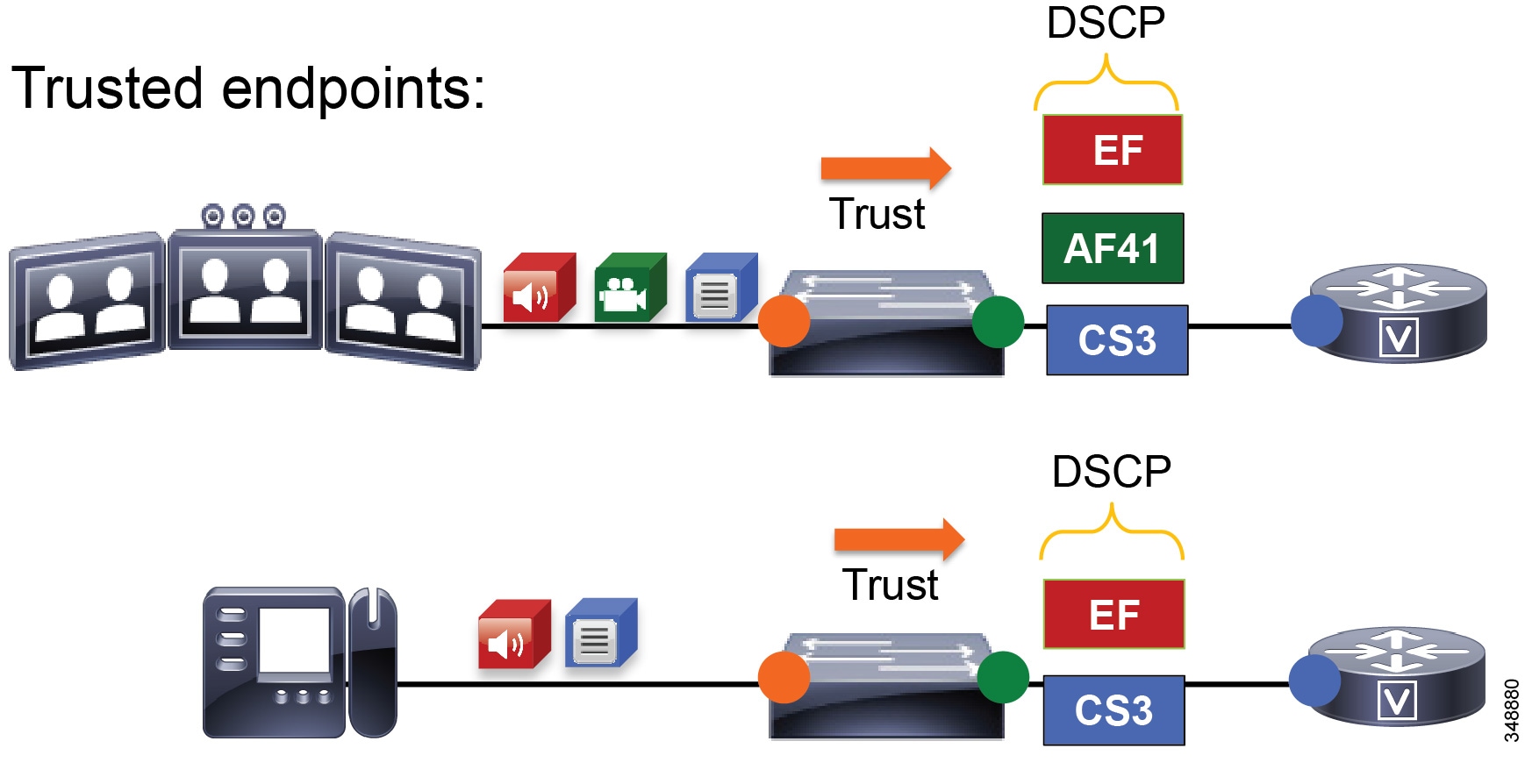
The administrator configures all access switches with a conditional QoS trust for IP phones and video and TelePresence endpoints, classified as follows:
- Audio streams of voice-only and video calls are marked EF.
- Video streams of video calls are marked AF41.
The administrator configures the Unified CM SIP Profile for trusted endpoints with the DSCP values listed in Table 13-18 .
|
|
|
|
|---|---|---|
At the WAN edge, on ingress it is expected that the packets arriving with a specific DSCP value have been trusted at the access layer or re-marked accordingly if they were not trusted at the access switch. As a failsafe practice, on ingress it is important to re-mark any untrusted traffic at the WAN edge that could not be re-marked at the access layer. While QoS is important in the LAN, it is paramount in the WAN; and as routers assume a trust on ingress traffic, it is important to configure the correct QoS policy that aligns with the business requirements and user experience. The WAN edge re-marking is always done on the ingress interface into the router, while the queuing and scheduling is done on the egress interface. The following example walks through the WAN ingress QoS policy as well as the egress queuing policy. Figure 13-86 illustrates the configuration and the re-marking process.
In Figure 13-86 the packets from both the trusted and untrusted areas of the network are identified and classified with the appropriate DSCP marking via the trust methods discussed or via a simple ACL matching on UDP port ranges. Keep in mind that this ACL could also match more granularly on IP address or some other attributes that would further limit the scope of the marking.
Figure 13-86 Example Router Ingress QoS Policy Process – 1
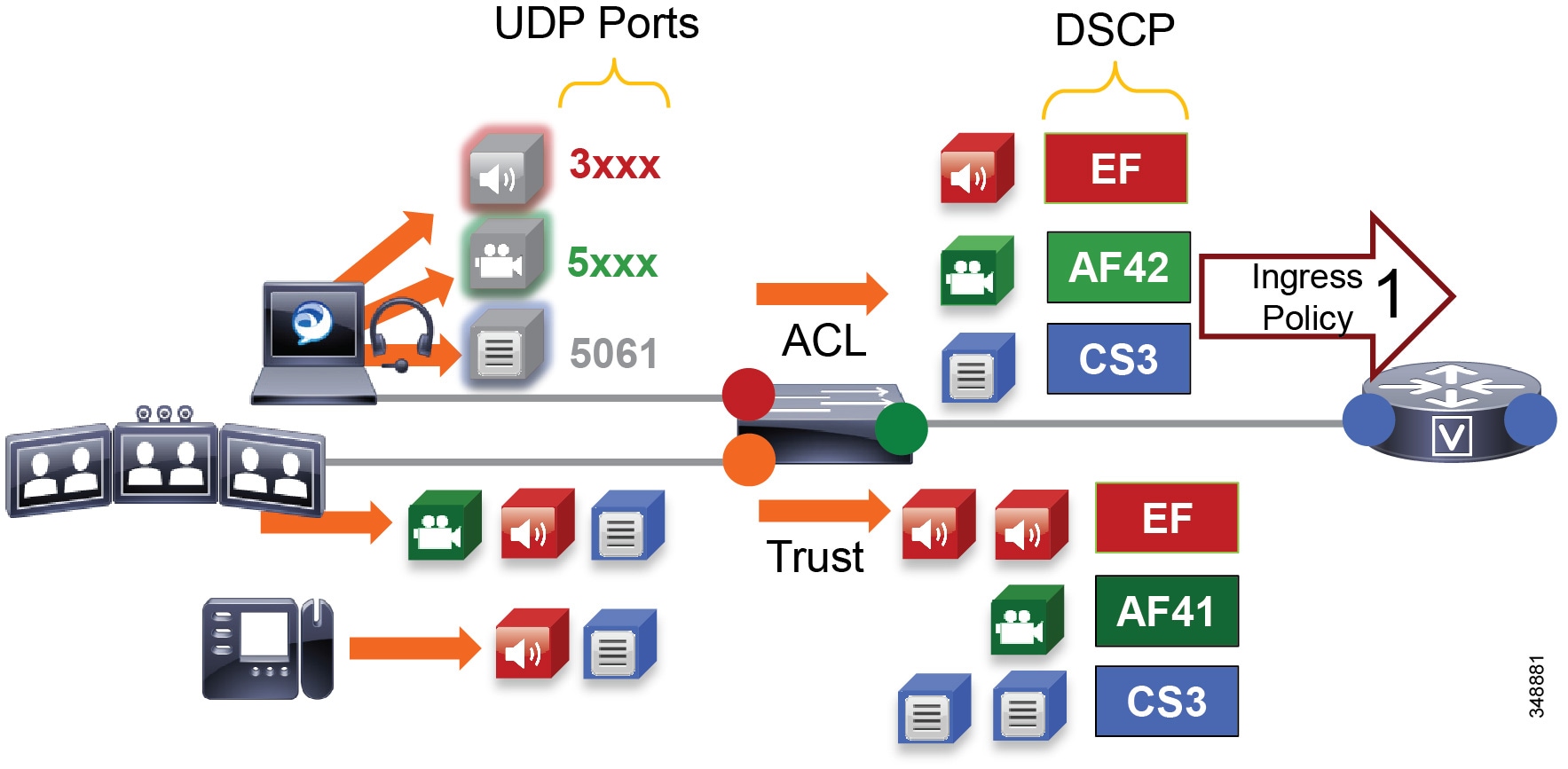
Figure 13-87 through illustrate the policy matching criteria and DSCP re-marking. The process involves the following steps shown in the figures:
1.![]() Packets arrive into the router ingress interface, which is configured with an input service policy (Figure 13-87).
Packets arrive into the router ingress interface, which is configured with an input service policy (Figure 13-87).
2.![]() The policy-map is configured with 4 classes of traffic setting the appropriate DSCP: Voice setting a DSCP of EF, Prioritized-Video setting a DSCP of AF41, Jabber-Video setting a DSCP of AF42, and Signaling setting a DSCP of CS3 (Figure 13-87).
The policy-map is configured with 4 classes of traffic setting the appropriate DSCP: Voice setting a DSCP of EF, Prioritized-Video setting a DSCP of AF41, Jabber-Video setting a DSCP of AF42, and Signaling setting a DSCP of CS3 (Figure 13-87).
3.![]() Each one of these classes matches a class-map of the same name configured with match-any criteria and a DSCP match as well as an ACL match. This match-any criteria means that the process will start top-down, and the first matching criteria will be executed and thus set the DSCP according to each class in the policy-map statements. Another option is match-all, which would require all criteria to be matched and thus would match DSCP and ACL. This, however, would not provide the intended functionality of re-marking either marked or unmarked traffic.
Each one of these classes matches a class-map of the same name configured with match-any criteria and a DSCP match as well as an ACL match. This match-any criteria means that the process will start top-down, and the first matching criteria will be executed and thus set the DSCP according to each class in the policy-map statements. Another option is match-all, which would require all criteria to be matched and thus would match DSCP and ACL. This, however, would not provide the intended functionality of re-marking either marked or unmarked traffic.
Figure 13-87 Example Router Ingress QoS Policy Process – 2

4.![]() The first match statement in the class-map is match dscp. If the traffic matches the DSCP, then DSCP is set again to the same value that was matched, as is configured in the policy map statements (Figure 13-88).
The first match statement in the class-map is match dscp. If the traffic matches the DSCP, then DSCP is set again to the same value that was matched, as is configured in the policy map statements (Figure 13-88).
Figure 13-88 Example Router Ingress QoS Policy Process – 3
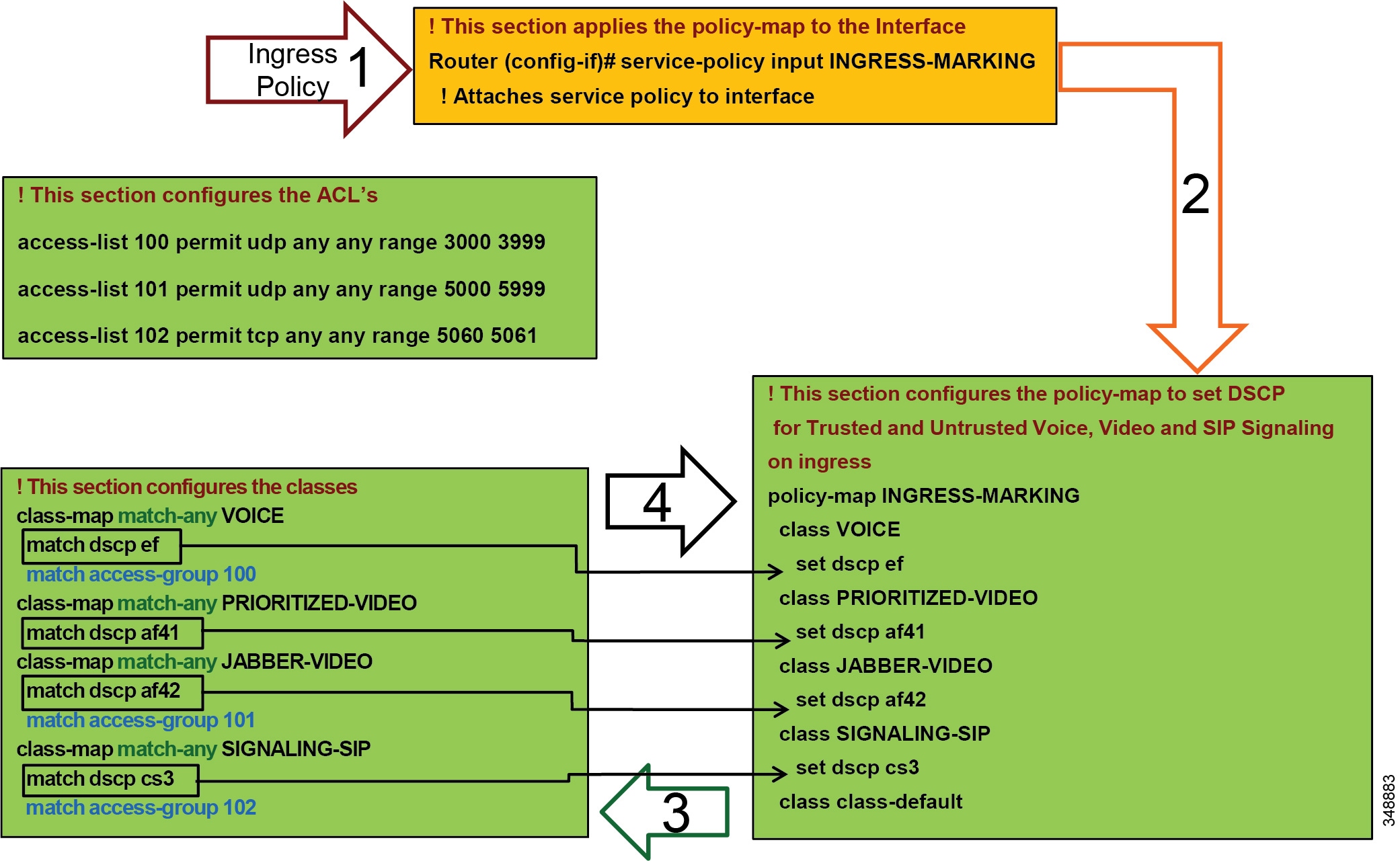
5.![]() If DSCP was not matched, then the next line in the class-map statement is parsed, which is the ACL that matches the UDP ports set in Unified CM for the Jabber clients (see Identification and Classification). When the ACL criteria (protocol and port range) are met, then the traffic is set as is configured in the corresponding policy map statements (Figure 13-89).
If DSCP was not matched, then the next line in the class-map statement is parsed, which is the ACL that matches the UDP ports set in Unified CM for the Jabber clients (see Identification and Classification). When the ACL criteria (protocol and port range) are met, then the traffic is set as is configured in the corresponding policy map statements (Figure 13-89).
Figure 13-89 Example Router Ingress QoS Policy Process – 4


Note![]() This is an example QoS ingress marking policy based on the Cisco Common Classification Policy Language (C3PL). Refer to your specific router configuration guide for information on how to achieve a similar policy on a Cisco router supporting C3PL and for any updated commands.
This is an example QoS ingress marking policy based on the Cisco Common Classification Policy Language (C3PL). Refer to your specific router configuration guide for information on how to achieve a similar policy on a Cisco router supporting C3PL and for any updated commands.
6.![]() The traffic goes to an outbound interface to be queued and scheduled by an output service policy that has 3 queues created: a Priority Queue called VOICE, a CBWFQ called VIDEO, and another CBWFQ called SIGNALING (Figure 13-90. This highlights the fact that this egress queuing policy is based only on DSCP as network marking occurring at the access switch and/or on ingress into the WAN router ingress interface. This is an example simply to illustrate the matching criteria and queues, and it does not yet contain the WRED functionality (covered in the next subsection). For more information on WRED, see the next section on WAN Queuing and Scheduling.
The traffic goes to an outbound interface to be queued and scheduled by an output service policy that has 3 queues created: a Priority Queue called VOICE, a CBWFQ called VIDEO, and another CBWFQ called SIGNALING (Figure 13-90. This highlights the fact that this egress queuing policy is based only on DSCP as network marking occurring at the access switch and/or on ingress into the WAN router ingress interface. This is an example simply to illustrate the matching criteria and queues, and it does not yet contain the WRED functionality (covered in the next subsection). For more information on WRED, see the next section on WAN Queuing and Scheduling.
Figure 13-90 Example Router Egress Queuing Policy Process – 1
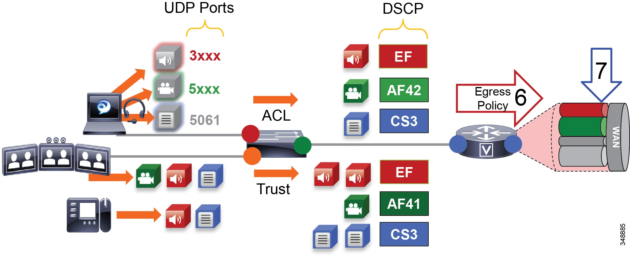
7.![]() The traffic is matched against the class-map match statements, and all traffic marked EF goes to the VOICE PQ, AF41 and AF42 traffic goes to the VIDEO CBWFQ, and CS3 traffic goes to the SIGNALING CBWFQ (Figure 13-91).
The traffic is matched against the class-map match statements, and all traffic marked EF goes to the VOICE PQ, AF41 and AF42 traffic goes to the VIDEO CBWFQ, and CS3 traffic goes to the SIGNALING CBWFQ (Figure 13-91).
Figure 13-91 Example Router Egress Queuing Policy Process – 2
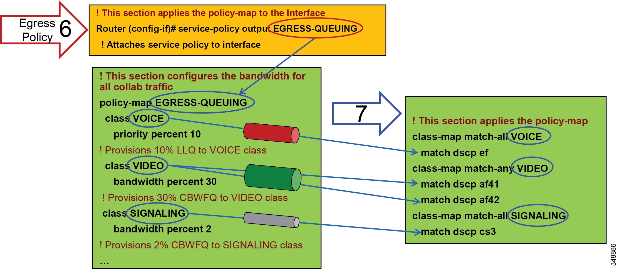

Note![]() This is an example egress queuing policy based on the Cisco Common Classification Policy Language (C3PL). Refer to your specific router configuration guide for information on how to achieve a similar policy on a Cisco router supporting C3PL and for any updated commands.
This is an example egress queuing policy based on the Cisco Common Classification Policy Language (C3PL). Refer to your specific router configuration guide for information on how to achieve a similar policy on a Cisco router supporting C3PL and for any updated commands.
WAN Queuing and Scheduling
This section discusses the interface queuing. Figure 13-92 illustrates the voice PQ, video CBWFQ, and WRED thresholds used for the CBWFQ:
- All audio from all endpoints (trusted and untrusted) marked EF is mapped to the PQ.
- Video calls and Jabber share the same CBWFQ:
–![]() EF for audio streams of video calls from trusted endpoints
EF for audio streams of video calls from trusted endpoints
–![]() AF41 for video streams of video calls from trusted endpoints
AF41 for video streams of video calls from trusted endpoints
–![]() EF for audio streams of all calls from Jabber clients
EF for audio streams of all calls from Jabber clients
–![]() AF42 for video streams of video calls from Jabber clients
AF42 for video streams of video calls from Jabber clients
–![]() Minimum and maximum thresholds for AF42:
Minimum and maximum thresholds for AF42:
Approximately 10% to 30% of queue limit
–![]() Minimum and maximum thresholds for AF41:
Minimum and maximum thresholds for AF41:
Approximately 45% to 100% of queue limit
Figure 13-92 Queuing and Scheduling Collaboration Media
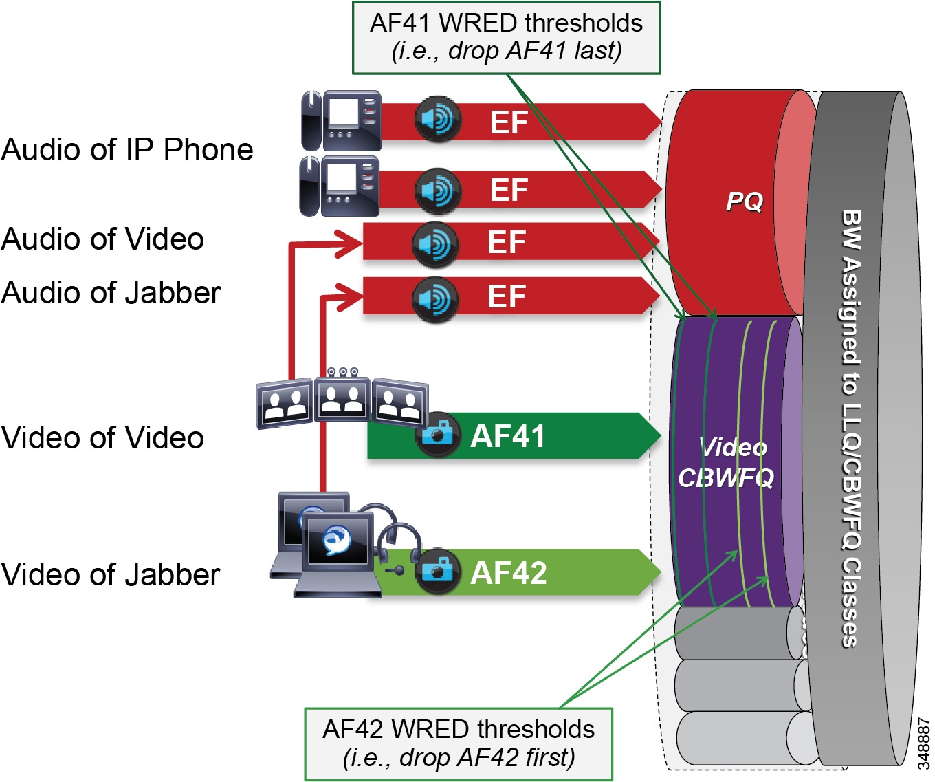
Weighted Random Early Detection (WRED) minimum and maximum thresholds are also configured in the Video CBWFQ. To illustrate how the WRED thresholds are configured, assume that the interface had been configured with a queue depth of 256 packets. Then following the guidelines listed above, the WRED minimum and maximum thresholds for AF42 and AF41 would be configured as illustrated in Figure 13-93.
Figure 13-93 Example of Video CBWFQ with WRED Threshold

Provisioning and Admission Control
This section addresses admission control and provisioning bandwidth to the queues for each site type.
As mentioned previously, admission control is not used in this example case to manage the video bandwidth but instead to manage the audio traffic to ensure that the PQ is not over-subscribed. And in this Example Enterprise #2, the voice pool in Enhanced Locations CAC will be admitting the audio for both the voice-only calls and the video calls.
In Unified CM this feature is enabled by setting the service parameter Deduct Audio Bandwidth from Audio Pool for Video Call to True under the Call Admission Control section of the CallManager service called. False is the default setting, and by default Unified CM deducts both audio and video streams of video calls from the video pool. This parameter will change that behavior and is key to the QoS alterations in Example Enterprise #2.
Figure 13-94 illustrates the various call flows, their corresponding audio and video streams, and the queues to which they are directed.
Figure 13-94 Provisioning and Admission Control
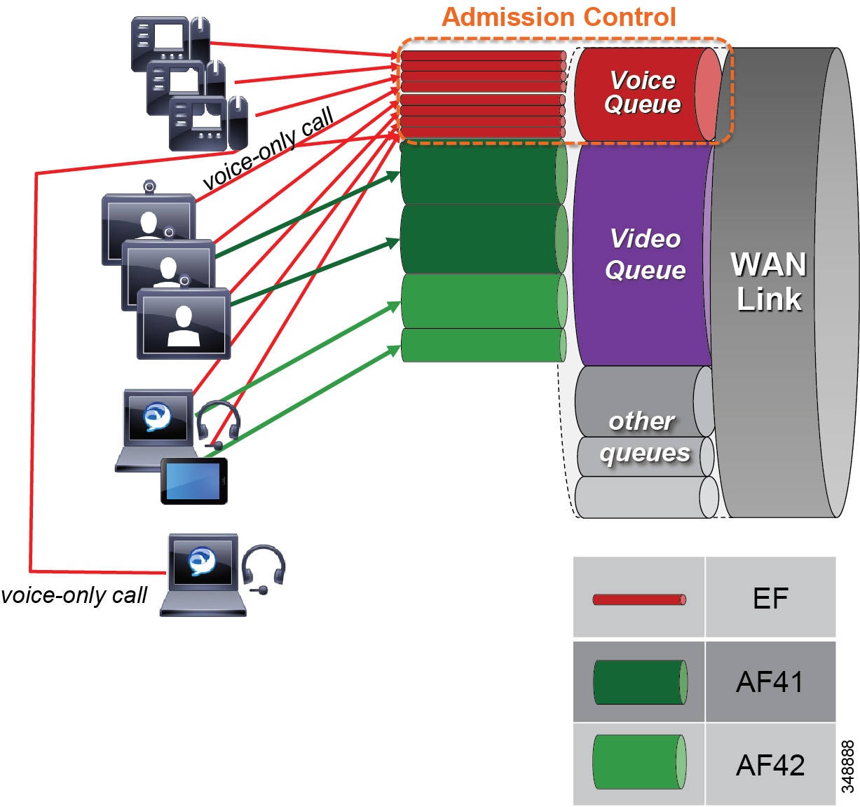
The example in Figure 13-94 uses the following configuration:
- Priority queue is provisioned for all calls from both trusted and untrusted endpoints, and it is protected by admission control (E-LCAC voice BW pool).
- Video queue is over-provisioned for room-based video systems:
–![]() Ratios are applied to bandwidth usage for desktop video endpoints.
Ratios are applied to bandwidth usage for desktop video endpoints.
–![]() Jabber video calls can use any bandwidth unused by video room systems.
Jabber video calls can use any bandwidth unused by video room systems.
–![]() During congestion, video streams of Jabber calls are subject to WRED drops and dynamically reduce video bit rate.
During congestion, video streams of Jabber calls are subject to WRED drops and dynamically reduce video bit rate.
Bandwidth Allocation Guidelines
The bandwidth allocations in Figure 13-95 are guidelines based solely on this Example Enterprise #2. They provide some guidance on percentages of available bandwidth for various common classes of Collaboration traffic. It is important to understand that bandwidth provisioning is highly dependent on utilization, and this will be different for each deployment and the user base being served at each site. The following examples provide a process to utilize for bandwidth provisioning. After provisioning the bandwidth, monitoring it and readjusting it are always necessary to ensure the best possible bandwidth provisioning and allocation necessary for an optimal user experience.
Figure 13-95 Bandwidth Allocation Guidelines

The following sections describe each site (Central, Large Branch, Small Branch, and Micro Branch) and the link bandwidth provisioned for each class based on the number of users and available bandwidth for each class. Keep in mind that these values are based on bandwidth calculated for Layer 3 and above. Therefore, they do not include the Layer 2 overhead, which is dependent on the link type (Ethernet, Frame-relay, MPLS, and so forth). See the chapter on Network Infrastructure, for more information on Layer 2 overhead.
Also, note that the audio portion of bandwidth for video calls is now deducted from the voice pool. So when provisioning the voice queue, this will include the audio bandwidth for both voice-only and video calls. These examples are the same as those for Example Enterprise #1. The only difference is that for Example Enterprise #2 the audio portion of bandwidth for video calls is deducted from the voice admission control pool, and the audio streams go into the voice queue.
Central Site Link (100 Mbps) Bandwidth Calculation
As illustrated in Figure 13-96, the Central Site has the following bandwidth requirements:
–![]() Immersive endpoint: 2 Mbps ∗ 1 call = 2 Mbps
Immersive endpoint: 2 Mbps ∗ 1 call = 2 Mbps
–![]() Video endpoints: 1.2 Mbps ∗ 30 calls ∗ 0.2 = 7.2 Mbps
Video endpoints: 1.2 Mbps ∗ 30 calls ∗ 0.2 = 7.2 Mbps
–![]() TelePresence Servers: 1.5 Mbps ∗ 40 calls ∗ 0.5 = 30 Mbps
TelePresence Servers: 1.5 Mbps ∗ 40 calls ∗ 0.5 = 30 Mbps
–![]() 55 Mbps – (2 Mbps + 7.2 Mbps + 30 Mbps) = 15.8 Mbps for Jabber media
55 Mbps – (2 Mbps + 7.2 Mbps + 30 Mbps) = 15.8 Mbps for Jabber media
18 Jabber video calls @ 576p, or 50 @ 288p
Immersive endpoints are sized for the busy hour. One endpoint is expected to be in a call across the WAN. This would be for a point-to-point call, since any conference call would terminate locally at the TelePresence server. It is important to take into account the worst-case scenario for the busy hour.
Video endpoints are sized for 20% WAN utilization (∗0.2). A possible total of 30 calls at 1.2 Mbps is based on the number of endpoints. But assuming only 20% WAN utilization in active calls over the WAN, compared to active local calls, gives the WAN utilization rate of above 7.2 Mbps.
TelePresence Servers are sized at an average bit rate of 1.5 Mbps to account for the average of various endpoint resolutions from remote sites. The TelePresence Server would then be able to support up to 40 calls total (local and remote), and this is multiplied by 50% (0.5) to account for the possibility of half of the TelePresence calls going over the WAN while the other half might be serving local endpoints.
In addition there is 15.8 Mbps for Jabber calls, which could be 18 calls at 576p, or 50 calls at 288p, or variations thereof. This gives an idea of what the Jabber video calls have available for bandwidth. When more Jabber video calls occur past the 15.8 Mbps, packet loss will occur and will force all Jabber clients to adjust their bit rates down. This can be either a very subtle process with no visible user experience implications if the loss rate is low as new calls are added, or it can be very disruptive to the Jabber video if there is an immediate and sudden loss of packets. The expected packet loss rate as new video calls are added is helpful in determining the level of disruption in the user experience for this opportunistic class of video.

Large Branch Link (34 Mbps) Bandwidth Calculation
As illustrated in Figure 13-97, the Large Branch site has the following bandwidth requirements:
–![]() Video endpoints: 1.2 Mbps ∗ 6 calls = 7.2 Mbps
Video endpoints: 1.2 Mbps ∗ 6 calls = 7.2 Mbps
–![]() 18.7 Mbps – 7.2 Mbps = 11.5 Mbps for Jabber media
18.7 Mbps – 7.2 Mbps = 11.5 Mbps for Jabber media
13 Jabber video calls @ 576p, or 36 @ 288p

Small Branch Link (10 Mbps) Bandwidth Calculation
As illustrated in Figure 13-98, the Small Branch site has the following bandwidth requirements:
–![]() Video endpoints: 1.2 Mbps * 2 calls = 2.4 Mbps
Video endpoints: 1.2 Mbps * 2 calls = 2.4 Mbps
–![]() 4 Mbps – 2.4 Mbps = 1.6 Mbps for Jabber media
4 Mbps – 2.4 Mbps = 1.6 Mbps for Jabber media
2 Jabber video calls @ 576p, or 5 @ 288p

Micro Branch Broadband Internet Connectivity (5 Mbps) Bandwidth Calculation
As illustrated in Figure 13-99, the Micro Branch site has the following bandwidth requirements:
- Broadband Internet connectivity + DMVPN to central site
- Configure interface of VPN router to match broadband uplink speed
- Enable QoS on VPN router to prevent bufferbloat from TCP flows
- Asymmetric download/upload broadband: consider limiting transmit bit rate on video endpoint

Large Branch with Constrained WAN Link (Enhanced Locations CAC Enabled for Video)
In specific branch sites with lower-speed WAN links, over-provisioning the video queue is not feasible (see Figure 13-100). ELCAC can be applied to these Location links for video to ensure that video calls do not over-subscribe the link bandwidth. This template requires using site-specific region configuration to limit maximum bandwidth used by video endpoints and Jabber clients. Also keep in mind that device mobility is required if Jabber users roam across sites.

Note![]() Because audio bandwidth for both voice-only and video calls is deducted from the voice CAC pool, there is no need for any queue bandwidth adjustment as is the case in Example Enterprise #1.
Because audio bandwidth for both voice-only and video calls is deducted from the voice CAC pool, there is no need for any queue bandwidth adjustment as is the case in Example Enterprise #1.
Figure 13-100 Large Branch with Constrained WAN Link (Enhanced Locations CAC Enabled for Video)

As illustrated in Figure 13-100, a Large Branch site with a constrained WAN link (10 Mbps) has the following bandwidth requirements:
–![]() Possible usage: 2 calls @ 576p (768 kbps) + 5 calls @ 288p (320 kbps) = 3,136 kbps
Possible usage: 2 calls @ 576p (768 kbps) + 5 calls @ 288p (320 kbps) = 3,136 kbps
–![]() Unified CM Location link bandwidth for video calls: 3.2 Mbps (L3 bandwidth)
Unified CM Location link bandwidth for video calls: 3.2 Mbps (L3 bandwidth)
–![]() Leaves room for L2 overhead, burstiness, and Jabber audio-only calls marked AF41
Leaves room for L2 overhead, burstiness, and Jabber audio-only calls marked AF41
 Feedback