- Introduction
- Install Cisco Prime Collaboration Deployment
- Upgrade Cisco Prime Collaboration Deployment
- Cisco Prime Collaboration Deployment Features
- Cisco Prime Collaboration Deployment Administrative Interface Elements
- Cisco Prime Collaboration Deployment Configuration and Administration
- CLI Commands and Disaster Recovery System
- CLI Commands for EnhancedSecurityMode and FIPS Mode
- CTL Update
- Best Practices
- Cisco Prime Collaboration Deployment Troubleshooting
- Cisco Prime Collaboration Deployment Considerations
- Network Address Translation Support
- Supported Tasks for Applications and Versions
- Upgrade Paths for Export Restricted and Unrestricted Software
- Supported ESXi Server Versions
- Cluster Inventory
- Task Management
- Migration Task
- Before You Begin
- Create a Migration Task
- Run a Migration Task
- Postmigration Tasks for Cisco Unified Communication Manager Nodes in the Cluster
- Post Migration Tasks for IM and Presence Service
- Migration Procedure Flow Charts
- Simple Migration
- Pre Release 8.0.1 Unified CM Network Migration
- Release 8.0.1 And Later Unified CM Network Migration
- Recovery of Original Cluster
- Check the Status of the Cluster Manager Service on All Source Nodes
- Upgrade Task
- Reuse Sequence from Previous Task
- Switch Versions Task
- Server Restart Task
- Readdress Task
- Install Task
- Edit and Expand Cluster Support
- Monitor Task Status
- Migration Task
Cisco Prime Collaboration Deployment Features
- Cisco Prime Collaboration Deployment Considerations
- Network Address Translation Support
- Supported Tasks for Applications and Versions
- Upgrade Paths for Export Restricted and Unrestricted Software
- Supported ESXi Server Versions
- Cluster Inventory
- Task Management
- Administration Tools
- FIPS 140-2 Compliance
- EnhancedSecurityMode Support
- Re-encryption through AES
- Limited Number of Sign-in Sessions
Cisco Prime Collaboration Deployment Considerations
Cisco Prime Collaboration Deployment allows a user to perform tasks (such as migration or upgrade) on servers that are in the inventory.
|
Step |
Tasks |
||
|---|---|---|---|
|
Step 1: Inventory Creation |
To perform any tasks, you must first have clusters in your inventory. To add a UC cluster that is already running UC applications to your inventory, click the open and close navigation button and choose the feature. To migrate an existing cluster to new virtual machines, click the open and close navigation button and choose . (See Migration Task.) To install a new cluster, click the open and close navigation button and choose the feature. (See Install Task.) If you are migrating an existing cluster to a new virtual machine cluster, or installing a new cluster, you must first add the ESXi Hosts that contain those virtual machines to your inventory. To add an ESXi host, click the open and close navigation button and choose . (See Add an ESXi Host Server.) |
||
|
Step 2: Create a Task |
You can create a task to perform an operation on a cluster in your inventory. During task creation, options allow you to:
To perform one of the following actions, select from these procedures:
|
||
|
Step 3: Monitor Tasks |
After a task is created, you can use the Monitoring window to view or track any task. You can also use this page to cancel, pause, or resume tasks. To view the tasks you created, see Monitor Task Status. |
||
|
Step 4: Administrative Tasks |
You can set up email notification. See Email Notification. |
Network Address Translation Support
To support application nodes behind the NAT, Cisco Prime Collaboration Deployment tracks the private IP address and the NAT IP address. Use Cisco Prime Collaboration Deployment to specify the NAT IP address for deployment nodes and the application. Cisco Prime Collaboration Deployment uses the NAT IP address to communicate with the application node. However, when you configure a node using the platformConfig.xml file, the node uses its private address.
Configure Cisco Prime Collaboration Deployment Behind the NAT
When Cisco Prime Collaboration Deployment is behind the NAT and communicates with an application virtual machine or an ESXi host, the communication occurs using the NAT IP address.
 Note | When Cisco Prime Collaboration Deployment is behind the NAT and application nodes are in a private network, the application nodes communicate with the NAT IP address. |
Use the NAT Settings window in the Administration menu to set the NAT IP address for Cisco Prime Collaboration Deployment. The NAT IP address that you enter on this window does not appear on any window on the GUI.
Supported Tasks for Applications and Versions
You can use Cisco Prime Collaboration Deployment to perform various tasks for Unified Communications applications. The following tables list the tasks that Cisco Prime Collaboration Deployment supports for each application.
Note | The releases listed in the tables do not specify the Engineering Special (ES)/ Service Update (SU) versions. To identify supported ES/SU versions that you can upgrade or migrate to through Cisco Prime Collaboration Deployment, see the release notes of the corresponding product, such as IM and Presence, Cisco Unified Communications Manager, and Unity Connection. |
Note | Cisco Prime Collaboration Deployment supports the destination version 10.x and above for an upgrade or a migration. The application versions 10.x and above support virtualization. If the source version is 8.x or 9.x on virtual machine, the upgrade task can upgrade to 10.x and above. However, if the source version is 8.x or 9.x on MCS, the upgrade task is not supported. A migrate cluster task can migrate to any of releases listed in the tables, irrespective of whether on MCS 7800 or virtual machine, to 10.x or higher version on a virtual machine. |
|
Task |
Release |
|---|---|
|
Cluster Discovery |
6.1(5), 7.1(3), 7.1(5), 8.0(1), 8.0(2), 8.0(3), 8.5(1), 8.6(1), 8.6(2), 9.0.(1), 9.1(1), 9.1(2), 10.0(1), 10.5(1), 10.5(2), 11.0(1), 11.5(1) |
|
Migrate Cluster (Install Application and Import Data from Old System) |
From 6.1(5), 7.1(3), 7.1(5), 8.0(1), 8.0(2), 8.0(3), 8.5(1), 8.6(1), 8.6(2), 9.0.(1), 9.1(1), 9.1(2), 10.0(1), 10.5(1), 10.5(2), 11.0(1), 11.5(1) To 10.x or 11.x |
|
Upgrade Cluster (Upgrade Application Version or Install COP Files) |
From 8.6(1), 8.6(2), 9.0.(1), 9.1(1), 9.1(2), 10.0(1), 10.5(1), 10.5(2), 11.0(1), 11.5(1) To 10.x or 11.x |
|
Restart |
8.6(1), 8.6(2), 9.0.(1), 9.1(1), 9.1(2), 10.0(1), 10.5(1), 10.5(2), 11.0(1), 11.5(1) |
|
Switch Version |
8.6(1), 8.6(2), 9.0.(1), 9.1(1), 9.1(2), 10.0(1), 10.5(1), 10.5(2), 11.0(1), 11.5(1) |
|
Fresh Install New Cluster or Edit or Expand an Existing Cluster |
10.x, 10.5(1), 10.5(2), 11.0(1), 11.5(1) |
|
Readdress (Change Hostname or IP Addresses for One or More Nodes in a Cluster) |
10.x, 11.0(1), 11.5(1) |
|
Task |
Release |
|---|---|
|
Cluster Discovery |
8.5(x), 8.6(x) |
|
Migrate Cluster (Install Application and Import Data from Old System) |
From 8.5(4), 8.6(3), 8.6(4), 8.6(5) To 10.x or 11.x |
|
Upgrade Cluster (Upgrade Application Version or Install COP Files) |
From 8.6(3), 8.6(4), 8.6(5) To 10.x or 11.x |
|
Restart |
8.6(3), 8.6(4), 8.6(5) |
|
Switch Version |
8.6(3), 8.6(4), 8.6(5) |
|
Fresh Install New Cluster or Edit or Expand an Existing Cluster |
Not applicable |
|
Readdress (Change Hostname or IP Addresses for One or More Nodes in a Cluster) |
Not applicable |
|
Task |
Release |
|---|---|
|
Cluster Discovery |
9.0(1), 9.1(1), 10.x, 11.0(1), 11.5(1) |
|
Migrate Cluster (Install Application and Import Data from Old System) |
From 9.0(1), 9.1(1), 10.x, 11.0(1), 11.5(1) To 10.x or 11.x |
|
Upgrade Cluster (Upgrade Application Version or Install COP Files) |
From 9.0(1), 9.1(1), 10.x, 11.0(1), 11.5(1) To 10.x or 11.x |
|
Restart |
9.0(1), 9.1(1), 10.x, 11.0(1), 11.5(1) |
|
Switch Version |
9.0(1), 9.1(1), 10.x, 11.0(1), 11.5(1) |
|
Fresh Install New Cluster or Edit or Expand an Existing Cluster |
10.x, 10.5(1), 10.5(2), 11.0(1), 11.5(1) |
|
Readdress (Change Hostname or IP Addresses for One or More Nodes in a Cluster) |
Not Supported |
|
Task |
Release |
|---|---|
|
Cluster Discovery |
8.5(1), 9.0, 9.0(2), and 10.x, 11.x |
|
Migrate Cluster (Install Application and Import Data from Old System) |
Not Supported |
|
Upgrade Cluster (Upgrade Application Version or Install COP Files) |
From 9.0(2), 10.x, 11.x To 10.x or 11.x |
|
Restart |
9.0(2), 10.x, 11.x |
|
Switch Version |
9.0(2), 10.x, 11.x |
|
Fresh Install New Cluster or Edit or Expand an Existing Cluster |
10.5(x), 11.x |
|
Readdress (Change Hostname or IP Addresses for One or More Nodes in a Cluster) |
10.5(x), 11.x |
|
Task |
Release |
|---|---|
|
Cluster Discovery |
8.6.1, 8.6.2, 9.x, 10.x, 11.x |
|
Migrate Cluster (Install Application and Import Data from Old System) |
Not Supported |
|
Upgrade Cluster (Upgrade Application Version or Install COP Files) |
From 8.6(x) to 8.6(x) From 8.6(x) to 9.x From 9.x to 9.x From 10.0(1) to 10.x From 10.x to 11.0 From 11.0 to 11.x |
|
Restart |
8.6(1), 8.6(2), 9.x, 10.x, 11.x |
|
Switch Version |
8.6(1), 8.6(2), 9.x, 10.x, 11.x |
|
Fresh Install New Cluster or Edit or Expand an Existing Cluster |
10.5(x), 11.x |
|
Readdress (Change Hostname or IP Addresses for One or More Nodes in a Cluster) |
10.5(x), 11.x |
Upgrade Paths for Export Restricted and Unrestricted Software
|
From |
To |
Task Types Supported |
|---|---|---|
|
Export Restricted (K9) |
Export Restricted (K9) |
Supported for Upgrade paths Supported for Migration paths |
|
Export Restricted (K9) |
Export Unrestricted (XU) |
Not supported for Upgrade paths Supported for Migration paths |
|
Export Unrestricted (XU) |
Export Restricted (K9) |
Not supported for Upgrade paths Not supported for Migration paths |
|
Export Unrestricted (XU) |
Export Unrestricted (XU) |
Supported for Upgrade paths Supported for Migration paths |
Supported ESXi Server Versions
Following table lists the supported ESXi server versions for a Cisco Prime Collaboration Deployment virtual machine (VM). This VM integrates through the VMware APIs with a virtualization host that is running VMs for Cisco Unified Communications Manager or other applications. To view the list of compatible versions of VMware vSphere ESXi server for a Cisco Prime Collaboration Deployment virtual machine that runs on a virtualization host, see http://docwiki.cisco.com/wiki/Unified_Communications_in_a_Virtualized_Environment.
Cluster Inventory
You must add a cluster to the Cisco Prime Collaboration Deployment inventory before you can use it in a task. The Discover Cluster feature is used to add existing clusters to the inventory. To create a new cluster by migrating an old cluster to new virtual machines, click Define Migration Destination Cluster. To install a new cluster, click Define New UC Cluster.
- Discover a Cluster
- Modify and View a Cluster
- Add an ESXi Host Server
- Create a Migration Cluster
- Add New Cluster for Fresh Install
Discover a Cluster
With the Discover Cluster feature, Cisco Prime Collaboration Deployment communicates with the servers that are already running Unified Communications applications and adds that cluster information into the Cisco Prime Collaboration Deployment inventory.
When you perform the Discover Cluster operation, the Cisco Prime Collaboration Deployment server communicates with the publisher of the cluster and retrieves the cluster information. Then, it communicates with each server, installs the ciscocm.ucmap_platformconfig.cop file on the server (to retrieve configuration information), and collects information about the hostname, IP, product type, and both active and inactive versions for that server.
Note | When the publisher is behind the NAT, providing the private IP address of the publisher does not reach to the node. You must provide the proper IP address for successful node discovery. |
For details on the supported applications, see "Supported Upgrade and Migration Tasks" in the Related Topics section.
Note | If a cluster includes Cisco Unified Communications Manager and Cisco Unified Presence (Cisco Unified Communications and IM and Presence Service servers), the Cluster Discovery discovers the Cisco Unified Presence or IM and Presence Service nodes as part of the Cisco Unified Communications Manager cluster. |
-
If you are using the Unified CM OS Admin interface for upgrade, you must upgrade the Cisco Unified Communications Manager publisher node and then upgrade the IM and Presence Services nodes to an MR or an ES Release.
-
If you are using the Cisco Prime Collaboration Deployment migration task, choose the Cisco Unified Communications Manager publisher node in addition to the IM and Presence Services nodes.
-
If you are using the Cisco Prime Collaboration Deployment upgrade task, you do not need to select the Cisco Unified Communications Manager publisher node if the first three digits of new version of IM and Presence Services match the first three digits of the currently installed version of Cisco Unified Communications Manager.
| Step 1 | From the Cisco Prime Collaboration Deployment application, click the open and close navigation button and choose . The Clusters window appears. | ||||
| Step 2 | Click the Discover Cluster button to discover the existing clusters. The Discover Cluster wizard appears. | ||||
| Step 3 | Enter details
in the following fields:
| ||||
| Step 4 | (Optional)Check the
Enable
NAT check box, and then click
Next.
| ||||
| Step 5 | Click Edit to add NAT IP address, and click OK. The Nat IP address is set for the hostname. | ||||
| Step 6 | Click Resume Discovery to resume the discovery of unreachable nodes. Cisco Prime Collaboration Deployment retries to discover the cluster with the NAT IP address instead of the private IP address and to get the cluster details, such as version. The discovery is successful when the cluster details appear on the window. | ||||
| Step 7 | Click Next. | ||||
| Step 8 | (Optional)Click
Assign
Functions to assign functions to each of the cluster nodes.
| ||||
| Step 9 | Click
Finish.
The
cluster appears in the
Clusters window, showing the cluster name, the
product and version, the cluster type as
Discovered, and the discovery status.
|
Modify and View a Cluster
You can select one or multiple virtual machines that you have added as nodes in a cluster to view and modify them.
Note | The cluster nodes that you need to install appear as editable and have Edit and Delete links. The installed cluster nodes appear dimmed and you cannot edit or delete them. |
Note | When you add new nodes to the installed cluster, all fields on Configure NTP Settings page appear dimmed and are non-editable. The fields on the other pages will populate the values of the already installed nodes as the default. If needed, you can change the values for the newly added nodes. |
| Step 1 | Discover a cluster by following the Discover a Cluster procedure. See Discover a Cluster. |
| Step 2 | Check the check box of one of the discovered or newly installed clusters to choose a cluster, and click the Edit link. |
| Step 3 | On the Edit Link window, view the details in the fields, and modify the details, as required. |
| Step 4 | Click OK. |
Add an ESXi Host Server
When you add an ESXi host into Cisco Prime Collaboration Deployment, you mount the Cisco Prime Collaboration Deployment server as a network file system (NFS) mount on that host. In future, if you remove your Cisco Prime Collaboration Deployment machine, you should first delete the ESXi host from the Cisco Prime Collaboration Deployment so that it does not cause a stale NFS mount on that host.
To communicate with an ESXi host server, Cisco Prime Collaboration Deployment requires either root access to the ESXi software or a nonroot user with Host and Virtual Machine privileges enabled. The administrator creates a nonroot user with the specific permissions for Cisco Prime Collaboration Deployment tasks, such as power on and off and mounting ISO or floppy, for fresh install or migration. The length of the nonroot user password must be less than 16 characters.
Note | When you shut down a Cisco Prime Collaboration Deployment server, we recommend that you use the utils system shutdown CLI command. |
Note | Make sure that the host with the Cisco Prime Collaboration Deployment VM and the host with the application VMs use the required Virtualization Software License. See Virtualization Software License Types. |
Create a Migration Cluster
-
Discover the existing cluster you wish to migrate. See the "Discover a Cluster" procedure at Discover a Cluster.
-
Define a migration cluster.
Note | After you define the migration cluster, see "Migration Task" at Migration Task to define when and how to perform the migration. |
| Step 1 | From the Cisco Prime Collaboration Deployment application, select . | ||
| Step 2 | Click Define Migration Destination Cluster. The Define Migration Destination Cluster wizard appears. | ||
| Step 3 | In the Specify
Clusters section, specify the name of the cluster, select the source UC cluster
from the drop-down list. Enter a name in the Destination Cluster Name field and
select one of the following Destination Network Settings options:
| ||
| Step 4 | Click Next. The Assign Destination Cluster Nodes window appears. | ||
| Step 5 | Click the
Assign
Destination Cluster Nodes button to select the destination virtual
machine for each source node.
| ||
| Step 6 | Select a
virtual machine, click
Next
Node to go to the next node in the cluster, and select another
virtual machine for the destination virtual machine, and click
Done.
| ||
| Step 7 | Click Next. The Configure NTP/SMTP Settings window appears. | ||
| Step 8 | Enter the
Network Time Protocol (NTP) server settings to be applied to the migration
nodes when the migration task runs, and optionally, enter the SMTP server
settings.
In a proxy TFTP setup, if a network migration is performed "off-cluster", you need to manually configure the new hostname and IP address of that off-cluster in the proxy TFTP. Off-cluster refers to situations where TFTP functionality is being performed by a proxy that is not part of that specific Unified Communications Manager cluster. During a migration, that TFTP server (that is not part of the cluster) is not modified. If you want to change the hostname or IP address of that server, you must do it as a separate process and not with Cisco Prime Collaboration Deployment. | ||
| Step 9 | Click Next. The Define DNS Settings window appears. | ||
| Step 10 | To change the
DNS setting for a node, select the node or nodes from the table and click
Assign
DNS Settings. Enter the primary and secondary DNS, then click
OK to apply the changes.
You cannot change the domain name during a migration. | ||
| Step 11 | Click
Finish.
The changes are saved and a row is added to the clusters table to reflect the new migration cluster that you have created. |
Add New Cluster for Fresh Install
| Step 1 | From the Cisco Prime Collaboration Deployment application, select . | ||
| Step 2 | Click Define New UC Cluster. The Define Cluster wizard appears. | ||
| Step 3 | In the Specify Cluster Name section, enter the cluster name, and click Next. The Add Virtual Machines window appears. | ||
| Step 4 | Click Add Node to add nodes to the cluster. The Add Node dialog box appears showing the list of the available VMs that are sorted by name and by host. | ||
| Step 5 | On the
Add
Node window, enter the network settings for the node that you have
added, choose the functions for the node, and choose a VM for this node. Select
the VM that you wish to add and then enter the following information in the
sections below the VM table:
| ||
| Step 6 | Click OK. The VM is added and is listed in the Cluster Name table. | ||
| Step 7 | (Optional) To add more nodes to the cluster, repeat steps 4 through 6. | ||
| Step 8 | Click Next. The Configure Cluster Wide Settings window appears. | ||
| Step 9 | Enter the OS administration credentials, application credentials, security password, SMTP settings, and certificate information for this cluster, and click Next. The Configure DNS Settings window appears. | ||
| Step 10 | (Optional) Add a DNS setting for a node, select the node, and click Assign DNS Settings. The Cisco Unified Contact Center Express application must use DNS. The Configure NTP Settings window appears. | ||
| Step 11 | Enter IP
address of at least one NTP server.
| ||
| Step 12 | Click Next. The Configure NIC Settings window appears. | ||
| Step 13 | (Optional) Choose the server, and enter an MTU size between 552 and 1500, and click Apply to Selected. | ||
| Step 14 | Click Next. The Configure Time Zones window appears. | ||
| Step 15 | Select a node, choose the region and time zone from the Region and Time Zones list boxes, and click Apply to Selected. | ||
| Step 16 | Click Finish. The new install cluster is listed on the Clusters screen, with a Cluster Type as New Install. The cluster is defined but is yet to be created. To install the cluster, create an install task. The install task uses the install cluster you have defined, and creates the cluster. |
Task Management
After you add your clusters and ESXi hosts to the Cisco Prime Collaboration Development inventory, you can create tasks to manage your clusters. Each task has the following common features:
-
Each task is applied to a single cluster.
-
The default sequence for each task (for example, what servers are affected and when) is applied based on the server functions you defined.
-
The sequence of each task can be customized to fit your needs.
-
Each task can be scheduled to start immediately or at a later date.
-
Tasks can also be created without a specific start time. You can then manually start the task through the Monitoring page at the appropriate time.
Migration, install, and upgrade tasks require you to select one or more Cisco Option Packages (COP) or ISO files. You must download these files from Cisco.com and upload them to the Cisco Prime Collaboration Deployment server before you create the task. You can use any SFTP client to upload the files using the "adminsftp" account and the OS Administation password. Upload migration and .iso install files into the /fresh_install directory, and place upgrade .iso files or .cop files to be installed on an existing server in the /upgrade directory.
Note | Migration and install .iso files must be bootable. |
- Migration Task
- Recovery of Original Cluster
- Check the Status of the Cluster Manager Service on All Source Nodes
- Upgrade Task
- Reuse Sequence from Previous Task
- Switch Versions Task
- Server Restart Task
- Readdress Task
- Install Task
- Edit and Expand Cluster Support
- Monitor Task Status
Migration Task
Before You Begin
To perform cluster migration, the destination virtual machine must be ready for installation before you create the migration task. Be sure that the following steps are completed:
- VMware—Deploy
the hardware for the new cluster and install ESXi.
Note
Make sure that the host with the Cisco Prime Collaboration Deployment VM and the host with the application VMs use the required Virtualization Software License. See Virtualization Software License Types.
- ISO file—Download the recommended OVA and ISO images for the target release, and use SFTP to send the ISO file to the Cisco Prime Collaboration Deployment server, /fresh_install directory.
- VMware—Deploy the Cisco-recommended OVA to create the VMs for the destination nodes. Create the appropriate number of target virtual machines on your ESXi hosts (one new virtual machine for each server in the existing cluster) using the Cisco OVAs that you downloaded in Step 2. Configure the network settings on new VMs.
- Cisco Prime Collaboration Deployment GUI—Add the ESXi Hosts that contain your virtual machines to the Cisco Prime Collaboration Deployment inventory. For information about adding an ESXi host to Cisco Prime Collaboration Deployment, see Add an ESXi Host Server.
- Cisco Prime Collaboration Deployment GUI—Ensure that you performed a cluster discovery for the existing cluster (source cluster) so that it appears in the Cluster Inventory. For information about cluster discovery, see Discover a Cluster.
- Cisco Prime Collaboration Deployment GUI—Create the
migration cluster (click the open and close navigation button and choose
) to define the mapping
between MCS source nodes and target virtual machines.
Important: When the migration cluster is created, you must indicate whether all destination nodes will maintain the same hostname or IP address, or whether some of these addresses will change. - Cisco Prime Collaboration Deployment GUI—Setup Email Notification (Optional)
- Cisco Prime Collaboration Deployment GUI—Create the migration task.
-
Install the ciscocm.migrate_export_10_0_1.sh_v1.1.cop.sgn cop file on both IM and Presence publisher and subscriber nodes.
Note | Cisco Prime Collaboration Deployment does not allow the change of host name during migration task. |
-
If you are migrating a cluster that is security enabled, see CTL Update for special instructions. If you are performing a migration with network migration (where one or more hostnames or IP addresses change between the source and destination nodes), update the IP addresses or hostnames of destination nodes in your DNS server before you begin the migration task.
-
You can specify a different NAT address for source and destination, so that the source is not abruptly shut down. If you want to perform a simple migration but need to specify different Network Address Translation (NAT) entries for source and destination, you must select "Network Migration" and provide the same details for source and destination (all hostnames and IP addresses).
Create a Migration Task
Follow these steps to create or edit a new migration task to simultaneously upgrade and migrate a cluster to new virtual machines.
Note the supported restricted and unrestricted paths. See "Supported Upgrade and Migration Tasks" and "Upgrade Paths for Export Restricted and Unrestricted Software" in the Related Topics section.
| Step 1 | Click the open and close navigation button and choose . | ||||||||||||
| Step 2 | Click the Add Migration Task. The Add Migration Task wizard appears. | ||||||||||||
| Step 3 | From the Source UC Cluster drop-down list, select the cluster on which the nodes to be migrated from are located. | ||||||||||||
| Step 4 | From the Destination Cluster drop-down list, select the destination cluster or migration map. The migration maps are associated with the source cluster you have selected. Click Next. | ||||||||||||
| Step 5 | In the
Choose
Migration Files section, choose the ISO file you wish to install on
the destination cluster by clicking
Browse. The
Choose
a Migration File window opens. Select the ISO file from the list and
click
OK.
| ||||||||||||
| Step 6 | Click Next. | ||||||||||||
| Step 7 | In the Set Start Time section, choose between scheduling a particular start time, starting the task immediately, or starting the task manually at some point in the future. Click Next. | ||||||||||||
| Step 8 | In the
Specify Migration Procedure section, you will see
the default sequence for the migration task. If you wish, you can change the
sequence of steps in the migration procedure. (For example, the default is to
install each subscriber individually. You might want to change this to install
more than one subscriber in a step.) You have the following options:
For more information about sequencing tasks, see the task management information at the beginning of this section. | ||||||||||||
| Step 9 | Click Next. | ||||||||||||
| Step 10 | In the Review section, you can review the selections that you made. You can also add notes to your new migration task. | ||||||||||||
| Step 11 | If there are no changes required, click Finish to add your new migration task. | ||||||||||||
| Step 12 | The new
migration task appears in the table on the Migrate screen.
|
Run a Migration Task
If you scheduled the task to start at a later date, or if you chose Manual Start, then the task is listed in the task list, but has not started yet. In this case, a validation button will be associated with the task. Click Validate to check the task before it runs. If there are any problems with the task (such as a missing ISO file, or VMs not in Off state), the validation will alert you, so the issues can be fixed before the task starts.
For a task that was scheduled to start, you can click the Start button to begin the task.
While the migration task is running, depending on the type of migration task, some user operations might be needed. For example, if you are performing a "migration with network migration," the sequence automatically inserts a "Forced Pause" into the sequence after all the servers have been installed. This will cause the migration task to pause after all the new servers are installed but before any of the source machines are shut down.
Consult the table below and the applicable Migration Procedure flow chart (see the "Migration Procedure Flow Charts" section) to determine if any user interaction will be needed during the migration task.
When the migration cluster is created, you must indicate whether all destination nodes will keep the same hostname or IP address, or if some of these addresses will be changing.
-
Using the source node settings for the all destination nodes option is referred to as a “simple migration” in the "Migration Procedure Flow Charts" section.
-
Entering new network settings for one or more destination nodes option is referred as "network migration" in the "Migration Procedure Flow Charts" section.
| Unified CM source cluster - from Release | Simple Migration or Network Migration | Unified CM source cluster - (secure or nonsecure) | User procedures to be performed during migration |
|---|---|---|---|
|
6.1(5), 7.1(3), 7.1(5) |
Simple migration | Secure | No steps are required during migration |
|
6.1(5), 7.1(3), 7.1(5) |
Simple migration | Nonsecure | No steps are required during migration |
|
6.1(5), 7.1(3), 7.1(5) |
Network migration | Secure | When migration task reaches the Forced Pause step, click the Resume button. |
|
6.1(5), 7.1(3), 7.1(5) |
Network migration | Nonsecure | When migration task reaches the Forced Pause step, click the Resume button. |
|
8.x, 9.x, and 10.x |
Simple migration | Secure | No steps required during migration |
|
8.x, 9.x, and 10.x |
Simple migration | Nonsecure | No steps required during migration |
|
8.x, 9.x, and 10.x |
Network migration | Secure |
When the migration task reaches the Forced Paused step, perform the following steps: |
|
8.x, 9.x, and 10.x |
Network migration | Nonsecure |
When the migration task reaches the Forced Paused step, perform the following steps: |
Postmigration Tasks for Cisco Unified Communication Manager Nodes in the Cluster
Consult the following table and the applicable migration Use Case flowchart to determine whether any user tasks must be performed after the migration task is successful.
| Unified CM source cluster - from Release | Simple Migration or Network Migration | Unified CM source cluster (Secure or Non-secure) | User procedures to be performed after migration |
|---|---|---|---|
|
6.1(5), 7.1(3), 7.1(5) |
Network migration | Secure | |
| Network migration | Nonsecure | ||
|
8.x, 9.x, and 10.x |
Network migration | Secure | |
| Network migration | Nonsecure |
Post Migration Tasks for IM and Presence Service
If the migrated cluster contains IM and Presence Service nodes, and you are performing a network migration, these postinstallation tasks must be performed for any pre-Release 10.x IM and Presence Service cluster.
| Command or Action | Purpose | |
|---|---|---|
| Step 1 | Configure certificates and certificate trust stores. | If the old cluster had
CA-signed certificates in any of the component trust stores, be aware that the
components contain self-signed certificates on the migrated Release 10.x
cluster.
Also, the
root and intermediate certificates of the Certificate Authority are not
preserved in their respective trust stores. You should sign the certificates
with the old Certificate Authority, similar to how it would have been done
initially.
For more information, see the Administration Guide for Cisco Unified Communications Manager Guide. |
| Step 2 | Configure intercluster peers. | If the old cluster had an intercluster peer relationship, you need to delete the configuration from all peer clusters. Once this is done, add the appropriate interclustering based on the network details of the new cluster. For example, Cluster A, Cluster B, and Cluster C are all intercluster peers. If Cluster A was migrated, then you should delete all interclustering configuration from the old Cluster A and likewise Cluster A from Cluster B and Cluster C and then add interclustering with the network details of the new Cluster A. You do not need to configure anything from the new Cluster A since the migration brings over the old data. For more information, see Deployment Guide for IM and Presence Service on Cisco Unified Communications Manager. |
| Step 3 | Re-publish SIP Federation. | If the old cluster was front-ending SIP Interdomain with Microsoft OCS/Lync/AOL or SIP Intradomain federation with OCS/Lync, then your enterprise will need to re-publish the DNS-SRV of your federating domain to reflect the new network details. If the far side has SIP static routes configured instead of DNS-SRV based routing, then the SIP static routes need to be changed to reflect the new network address. Similarly, all intermediate network elements (including ASA or any other similar components that route or inspect traffic to the old cluster from the external federation entities) need to be re-configured for successful routing to the new cluster. For Interdomain configuration, see Interdomain Federation for IM and Presence Service on Cisco Unified Communications Manager. For Intradomain federation, see Partitioned Intradomain Federation for IM and Presence Service on Cisco Unified Communications Manager. |
| Step 4 | Re-publish XMPP Federation. | If the old cluster was front-ending XMPP Interdomain federation to any external XMPP servers, then your enterprise will need to republish your federating domain's DNS-SRV records to reflect the new network details. Refer to Interdomain Federation for IM and Presence Service on Cisco Unified Communications Manager. |
| Step 5 | Configure Cisco Jabber/Cisco Unified Personal Communicator connectivity. | Jabber or Unified Personal Communicator caches the hostname information from the old cluster and does not have new hostname information unless you are able to push the configuration to the desktop of the user, or that user manually enters one of the node names. A fail safe approach for users that are unassigned from the old cluster, and as a result are unable to log in, involves the user manually entering the hostname or IP address of one of the nodes in the new cluster (of which they were informed of prior to migration). In this scenario, the user's client finds the right home node by way of redirected login. |
Migration Procedure Flow Charts
Use the following task flows as a guide to perform migration tasks.
Simple Migration
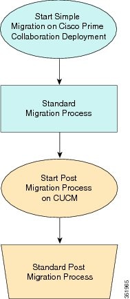
Note | Cisco Prime Collaboration Deployment does not support migration of Business Edition 5000 Appliance running on MCS 7828H3. |
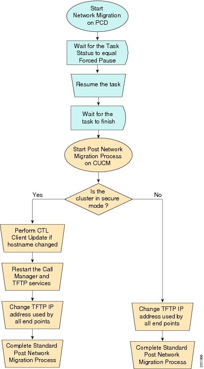
Pre Release 8.0.1 Unified CM Network Migration
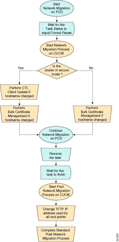
Release 8.0.1 And Later Unified CM Network Migration
Recovery of Original Cluster
Use the following procedure when a cluster fails to migrate successfully, and some nodes are installed on the new cluster.
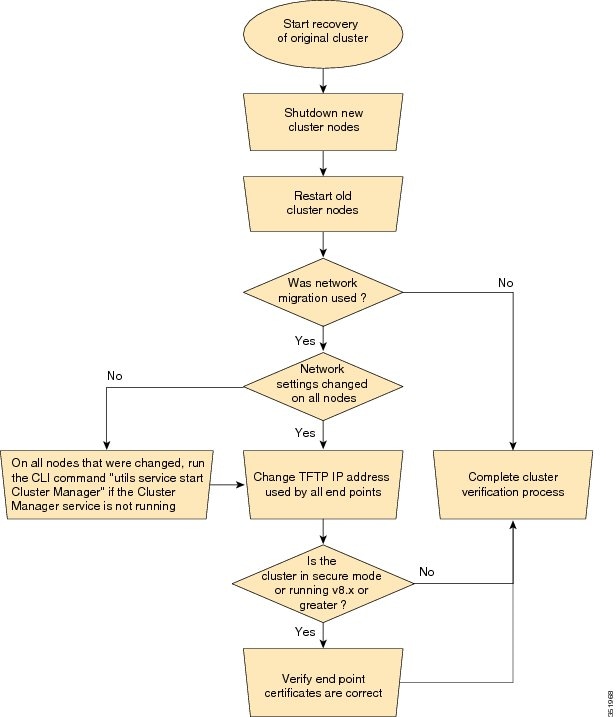
Check the Status of the Cluster Manager Service on All Source Nodes
The steps below are used if a migration task fails when there were network migration changes on one or more nodes. Following the failure, you may need to perform some steps to get the old cluster nodes running again. See the flow chart above for all steps to be followed. Below are detailed steps for running the CLI command to restart cluster manager on old nodes.
Perform the following steps manually on all subscriber nodes that were supposed to have network changes (for example, hostname, IP address, or both) after all old cluster nodes are up and running.
Use cases that may require the restart of Cluster manager on source nodes are:
Use Case 1
No hostname and no IP address change on Publisher, host name change on Subscriber
The user is required to check Cluster Manager service on source Subscriber
Use Case 2
No hostname and no IP address change on Publisher, IP address change on Subscriber
The user is required to check Cluster Manager service on source Subscriber
Use Case 3
No hostname and no IP address change on Publisher, hostname and IP address change on Subscriber
The user is required to check Cluster Manager service on source Subscriber
Use Case 4
No hostname change on Publisher, IP address change on Publisher, no hostname and no IP Subscriber
The user is required to check Cluster Manager service on source Publisher
| Step 1 | Enter the following CLI
command at the command prompt:
utils service list. The following output appears: Requesting service status, please wait... System SSH [STARTED] Cluster Manager [STOPPED] |
| Step 2 | If Cluster Manager Service status is STOPPED, type the following command to start the service on the old subscriber node: utils service start Cluster Manager |
Upgrade Task
Create an Upgrade Task
Use the upgrade task to perform software version upgrades on a cluster. You can also use an upgrade task to install .cop files on all or a subset of servers in a cluster.
To know the supported applications, releases, and versions, see the see "Supported Upgrade and Migration Tasks" and "Upgrade Paths for Export Restricted and Unrestricted Software" in the Related Topics section.
Note | Cisco Prime Collaboration Deployment uses the standard upgrade process, and therefore the standard validation rules are applied. For more information, see the application-specific documentation. |
Note |
|
Use the Add Upgrade Task wizard to create and edit upgrade tasks.
To create or edit a new upgrade task to automatically run on one or more clusters at scheduled times, follow these steps.
-
Note the supported restricted and unrestricted paths. See "Supported Upgrade and Migration Tasks" and "Upgrade Paths for Export Restricted and Unrestricted Software" in the Related Topics section.
-
Perform a cluster discovery for the cluster that you wish to upgrade, so it appears in the Cluster Inventory. See Discover a Cluster.
-
Download the ISO files you wish to upgrade to, and use SFTP to send this file to Cisco Prime Collaboration Deployment in the upgrade folder. If you are using the upgrade task to install a .cop file, upload the .cop file to the /upgrade folder using an SFTP client.
-
For the application servers in the cluster to be upgraded, ensure that the Platform Administrative Web Service is active on that server.
| Step 1 | Click the open and close navigation button and choose from the main menu. | ||||||||||||
| Step 2 | Click Add Upgrade Task. | ||||||||||||
| Step 3 | From the Cluster drop-down list, select the cluster on which the nodes to be upgraded are located. | ||||||||||||
| Step 4 | From the Products drop-down list, select the products to be upgraded. | ||||||||||||
| Step 5 | Select the nodes that are part of the upgrade from the list of nodes. | ||||||||||||
| Step 6 | Click
Next.
| ||||||||||||
| Step 7 | Click the
respective
Browse buttons to select the upgrade files from the
file server.
| ||||||||||||
| Step 8 | Select a valid
upgrade file or files.
| ||||||||||||
| Step 9 | Click Choose File. | ||||||||||||
| Step 10 | Click
Next.
| ||||||||||||
| Step 11 | Select the
date and time when you want the upgrade task to begin. You have the following
options to schedule upgrades:
| ||||||||||||
| Step 12 | Click Next. | ||||||||||||
| Step 13 | Specify the
sequence of steps to complete the task. You have the following options:
| ||||||||||||
| Step 14 | Click OK. | ||||||||||||
| Step 15 | Click
Next.
| ||||||||||||
| Step 16 | See the Review section to verify the details of the task you created. You can add notes for the task, if necessary. The notes are saved with the task and are visible if the task is edited before completion. | ||||||||||||
| Step 17 | Click Finish to schedule the task. |
Reuse Sequence from Previous Task
The Reuse Sequence from Previous Task feature uses a previously defined task sequence in the task you are currently creating. This feature is useful for upgrade, restart, switch version, migration, and readdress tasks. It allows you to reuse a previously configured task sequence as opposed to having to rescript the sequence from scratch.
During task creation, the task wizard progresses to the sequence pane where a user can configure the ordering and pause characteristics. If there is a task in the system of similar type, the sequence from that task is presented as the default sequence.
In this case, a check box labeled Use Last Configured Run Sequence is visible just above the sequence table. You can check the check box to use the sequence from the previous task or leave the check box unchecked to use the default sequence that the system generates.
To be considered a task of similar type, the selected cluster, task type, and nodes in the task must match exactly. If multiple tasks meet the similar type criteria, the most recently created task is used and its sequence is presented as the default to the user.
In the case of an upgrade task, there is an additional requirement. The type of installation must be either ISO based or COP based. The COP and ISO installations can be performed with different sequencing.
Switch Versions Task
Create a Switch Versions Task
Use the switch versions task to automatically switch one or more nodes in a cluster to the upgraded or inactive version.
Use the Switch Versions Task wizard to create and edit switch versions tasks.
To know which applications and releases are supported for upgrade tasks, see "Supported Upgrade and Migration Tasks" and "Upgrade Paths for Export Restricted and Unrestricted Software" in the Related Topics section.
To create or edit a switch versions task to automatically switch one or more nodes in a cluster to the upgraded or inactive version at scheduled times, follow this procedure.
Note | The Automatic Switch version option is not available on clusters which contain Unity Connection nodes. For clusters with Cisco Unity Connection, create an upgrade task and then create a switch version task to switch to the new version. You can create the switch version task after the upgrade task runs successfully. |
-
Perform a cluster discovery for the cluster on which you want to switch versions, so that the cluster appears in the Cluster inventory. See Discover a Cluster. If you previously used Cisco Prime Collaboration Deployment to upgrade or migrate a cluster, the cluster should already be in the inventory.
-
For each application server in the cluster, ensure that the Platform Administrative Web Service is active on that server.
| Step 1 | Click the open and close navigation button and choose from the main menu. | ||||||||||||
| Step 2 | Click Add Switch Versions Task. | ||||||||||||
| Step 3 | From the Cluster drop-down list, select the cluster on which you want to switch the versions. | ||||||||||||
| Step 4 | Select the
version to which you want all the nodes to be switched.
| ||||||||||||
| Step 5 | Click Next. | ||||||||||||
| Step 6 | Select the
date and time when you want the switch versions task to begin. You have the
following options to schedule switch versions task:
| ||||||||||||
| Step 7 | Click Next. | ||||||||||||
| Step 8 | Specify the
sequence of steps to complete the task. You have the following options:
| ||||||||||||
| Step 9 | Click OK. | ||||||||||||
| Step 10 | Click
Next.
| ||||||||||||
| Step 11 | Use the Review section to verify the details of the task that you created. You can add notes for the task if required. The notes are saved with the task and are visible if the task is edited before completion. | ||||||||||||
| Step 12 | Click Finish to schedule the task. |
Server Restart Task
To know which applications and releases are supported for upgrade tasks, see "Supported Upgrade and Migration Tasks" and "Upgrade Paths for Export Restricted and Unrestricted Software" in the Related Topics section.
Create a Server Restart Task
Use the Restart Task wizard to create and edit restart tasks.
To create or edit a restart task to automatically restart one or more nodes in a cluster at scheduled times, follow this procedure.
-
Perform a cluster discovery for the cluster you wish to restart, so that it appears in the Cluster inventory. See Discover a Cluster.
-
For each application server in the cluster, ensure that the Platform Administrative Web Service is active on that server.
-
If you are using Cisco Prime Collaboration Deployment Readdress Task with virtual machine of an application, ensure that you follow the application's rules for changing IP and hostname—either one at a time or simultaneously.
| Step 1 | Click the open and close navigation button and choose from the main menu. | ||||||||||||
| Step 2 | Click Add Server Restart Task. The Add Restart Task wizard appears. | ||||||||||||
| Step 3 | From the Clusters drop-down list, select the cluster on which you want to restart the nodes. | ||||||||||||
| Step 4 | From the table, select the nodes to be restarted. If you do not select any nodes, you cannot continue. | ||||||||||||
| Step 5 | Click Next. | ||||||||||||
| Step 6 | Select the
date and time when you want the server restart task to begin. You have the
following options to schedule restart tasks:
| ||||||||||||
| Step 7 | Click Next. | ||||||||||||
| Step 8 | Specify the
sequence of steps to complete the task. You have the following options:
| ||||||||||||
| Step 9 | Click OK. | ||||||||||||
| Step 10 | Click
Next.
| ||||||||||||
| Step 11 | See the Review section to verify the details of the task you created. You can add notes for the task if required. The notes are saved with the task and are visible if the task is edited before completion. | ||||||||||||
| Step 12 | Click Finish to schedule the task. |
Readdress Task
Create a Readdress Task
Use the readdress task change the hostname or IP address for one or more nodes in a cluster. To use the readdress feature, the servers must be Release 10.0 or later.
Note the difference between a hostname and a fully qualified domain name (FQDN) The network-level DNS default domain name of the node is combined with the hostname to form the FQDN for the node. For example, a node with hostname "cucm-server" and domain "example.com" has an FQDN of "imp-server.example.com."
Note | Cisco Prime Collaboration Deployment does not support changing the FQDN, only hostnames. |
Use the Readdress Task wizard to create and edit readdress tasks.
-
If you have not already done so, perform a cluster discovery for the cluster you wish to readdress, so that it appears in the Cluster inventory. See Discover a Cluster.
-
If you are using Cisco Prime Collaboration Deployment Readdress Task with virtual machine of an application, ensure that you follow the application's rules for changing IP and hostname—either one at a time or simultaneously.
| Step 1 | Click the open and close navigation button and choose from the main menu. | ||||||||||||
| Step 2 | Click Add Readdress Task. | ||||||||||||
| Step 3 | From the Cluster drop-down list, select the cluster on which you want to change the address of the nodes. Click View Nodes to view the Cluster nodes. | ||||||||||||
| Step 4 | Click Next. | ||||||||||||
| Step 5 | Click
Edit next to a node to enter an alternate Hostname,
IP Address, Subnet Mask or Gateway.
| ||||||||||||
| Step 6 | Click OK. | ||||||||||||
| Step 7 | Click
Next.
When you click Next, Cisco Prime Collaboration Deployment performs a validation test automatically. If the test on a cluster fails, the error message describes the failed test. You can continue to create the tasks, but you must resolve the errors described or the task will fail. | ||||||||||||
| Step 8 | Select the
date and time when you want the readdress task to begin. You have the following
options to schedule readdress tasks:
| ||||||||||||
| Step 9 | Click Next. | ||||||||||||
| Step 10 | Specify the
sequence of steps to complete the task. You have the following options here:
| ||||||||||||
| Step 11 | Click OK. | ||||||||||||
| Step 12 | Click
Next.
| ||||||||||||
| Step 13 | See the Review section to verify the details of the task you created. You can add notes for the task if required. The notes are saved with the task and are visible if the task is edited before completion. | ||||||||||||
| Step 14 | Click Finish to schedule the task. |
Run a Readdress Task
If you scheduled the task to start at a later date, or if you chose Manual Start, then the task will be listed in the task list but will not start yet.
For a task that was scheduled for manual start, click the Start button that is associated with this task to begin the task.
While the readdress task is running, if there is more than one server to be readdressed in the task, some user operations are needed. The readdress task sequence automatically inserts a Forced Pause into the sequence after the address of a server is changed.
The forced pause allows you to perform manual steps, such as updating DNS entries and server entries on the Unified Communications publisher node interface (). It also allows you to check the phones associated with the server successfully registered. User needs to perform these steps before resuming the readdress task in the interface for other Unified Communications nodes as well. After the readdress task resumes, the system replicates the updates successfully.
For more information, see Administration Guide for Cisco Unified Communications Manager.
Before running a readdress task, you may need to perform certain steps (for example, updating entries on the DNS server).
It is very important that you read Administration Guide for Cisco Unified Communications Manager before you run the readdress task.
Post Readdress Task
When you determine that the server successfully changed the address, go to the Cisco Prime Collaboration Deployment GUI and click Resume to resume the task.
The Cisco Prime Collaboration Deployment server proceeds to the next server in the sequence to be readdressed. Repeat the steps of waiting for the forced pause, checking the server state, and resuming the task, when the server readdress is verified.
Install Task
Create an Install Task
-
VMware—Deploy the hardware for the new cluster and install ESXi
Note
Make sure that the host with the Cisco Prime Collaboration Deployment VM and the host with the application VMs use the required Virtualization Software License. See Virtualization Software License Types.
-
ISO files—Download the necessary OVA and ISO images for target release, and use SFTP transfer the ISO files to the /fresh_install directory of Cisco Prime Collaboration Deployment.
Note
The ISO file must be bootable.
Note
Do not edit the file name of the bootable ISO that is being used for a PCD task.
-
VMware—Deploy Cisco-recommended OVA to create the VMs for the nodes to be installed. Create the appropriate number of target virtual machines on your ESXi hosts (one new virtual machine for each server to be installed in the cluster) using the Cisco OVAs that you downloaded in Step 2. Configure the network settings on new VMs.
-
Cisco Prime Collaboration Deployment GUI—Add the ESXi Hosts that contain your virtual machines to the Cisco Prime Collaboration Deployment inventory. For information about adding and ESXi host to Cisco Prime Collaboration Deployment, see Add an ESXi Host Server.
-
Cisco Prime Collaboration Deployment GUI—Define the new installation cluster (click the open and close navigation button and choose ) to define the nodes to be installed, and their associated virtual machines. (See Add New Cluster for Fresh Install.)
- Cisco Prime Collaboration Deployment GUI—Setup Email Notification (Optional)
- Cisco Prime Collaboration Deployment GUI—Create the Install task.
-
Be sure to enter the IP addresses or hostnames of the cluster nodes to be installed into your DNS server before you create the install task.
Add Install Task
Follow this procedure to automatically install one or more nodes in a cluster at scheduled times.
| Step 1 | Click the open and close navigation button and choose from the main menu. | ||||||||||||
| Step 2 | Click
Add
Install Task.
| ||||||||||||
| Step 3 | From the Installation Cluster drop-down list, select the cluster on which the nodes to be installation are located. | ||||||||||||
| Step 4 | Click Next. | ||||||||||||
| Step 5 | Click the
respective
Browse buttons to select the Unified Communications
Manager Installation file and the Cisco Unified Presence Installation file from
the server.
| ||||||||||||
| Step 6 | Click Choose File. | ||||||||||||
| Step 7 | Click
Next.
| ||||||||||||
| Step 8 | Select the
date and time when you want the upgrade task to begin. You have the following
options to schedule upgrades:
| ||||||||||||
| Step 9 | Click Next. | ||||||||||||
| Step 10 | Specify the
sequence of steps to complete the task. You have the following options:
| ||||||||||||
| Step 11 | Click OK. | ||||||||||||
| Step 12 | Click
Next.
| ||||||||||||
| Step 13 | See the Review section to verify the details of the task you created. You can add notes for the task if required. The notes are saved with the task and are visible if the task is edited before completion. | ||||||||||||
| Step 14 | ClickFinish to schedule the install task.
|
Run an Install Task
If you scheduled a task to start at a later date or if you chose Manual Start, the task is listed in the Task list, but has not started yet. In this case, a validation button is associated with the install task. Click Validation to check the task before you run it. By running validation before you start the task, you are alerted to any potential problems with the task (such as a missing ISO file or VMs not in the Off state). You can then fix these issues before you start the task.
Note | Clicking the Validation button will not start the task; this button only checks the resources to be used when the task starts. |
For a task that was scheduled for manual start, click the Start button that is associated with this task to begin the task.
When a fresh install task includes more than just one server, some user interaction is required while the task is running. The installation task automatically installs the Unified Communications Manager publisher first, and then the task sequence will have a forced pause. This forced pause stops the install task to allow the user to go to the Unified Communications Manager GUI of the newly installed publisher, and add the other servers in the cluster into the window. To define the subsequent nodes, click Add New and configure the server.
After all the subscribers to be installed in this cluster (Unified Communications Manager subscribers, IM and Presence Service publisher and IM and Presence Service subscribers) are added to the Unified Communications Manager publisher GUI, return to the Monitoring page in the Cisco Prime Collaboration Deployment GUI and click the Resume button for the install task to resume. The install task continues and installs the Unified Communications Manager or IM and Presence Service software on the subsequent server (or servers).
Cancel Install Task
Use this procedure to cancel a fresh install task or an existing installation in a migration task.
| Step 1 | From the Cisco Prime Collaboration Deployment application, click the open and close navigation button and choose from the main menu. The existing install tasks appear in the Task List section. | ||
| Step 2 | Select an
existing install task and click
Cancel.
|
Post-Install Task
After the install task, no further actions are required. The new cluster is ready for use.
Edit and Expand Cluster Support
If you deployed a Cisco Unified Communications Manager cluster, the Edit and Expand Cluster support feature in Cisco Prime Collaboration Deployment eliminates migration issues and barriers. You can perform the following actions:
-
Add IM and Presence Service to an existing Unified Communications Manager cluster.
-
Add new nodes to the existing cluster—for example, add subscriber nodes.
-
Select nodes from a cluster to perform installation.
This feature works with only a previously installed 10.x or later system and uses the Fresh Install Task to add the nodes.
Note | After you add and install new nodes to an existing cluster, if you later perform the Discovery task, the entire cluster with the new nodes is discovered. |
Edit or Delete a New Install Cluster
Edit or delete an added new node that has not yet been installed. A node that has not been installed appears active.
| Step 1 | From the Cisco Prime Collaboration Deployment application, click the open and close navigation button and choose . | ||
| Step 2 | Click a cluster that has the cluster type as New Install and click Edit. | ||
| Step 3 | In the Specify Cluster Name section, view the pre-populated cluster name, and click Next. | ||
| Step 4 | In the Add Virtual Machines section, select a node from the existing nodes, and click Edit. The Add Node window appears. | ||
| Step 5 | In the Add Node window, edit the node details, and click OK. | ||
| Step 6 | In the Configure Cluster Wide Settings section, edit the OS administration credentials, application credentials, security password, SMTP settings, and certificate information for all nodes of a cluster, as required, and click Next. | ||
| Step 7 | (Optional) In
the Configure DNS Settings section, edit the DNS settings for the migration
cluster nodes, and click
Next.
| ||
| Step 8 | In the
Configure NTP Settings section, edit the configuration of the NTP servers for
the nodes in a cluster, and click
Next.
| ||
| Step 9 | (Optional) In the Configure NIC Settings section, choose a server, and enter an MTU size between 552 and 1500, click Apply to Selected, and then click Next. | ||
| Step 10 | In the
Configure Time Zones section, select a node, edit the region and time zone from
the Region and Time Zones list boxes, click
Apply
to Selected, and then click
Finish.
|
Edit or Delete a Discovered Cluster
You can edit or delete a node that has not yet been installed. A node that has not been installed appears active and the installed nodes appear inactive.
Note | After you add or install a new node, you cannot delete the node with this feature. You must delete the node from an existing installed cluster by using your application administration web page or the CLI. |
| Step 1 | From the Cisco Prime Collaboration Deployment application, click the open and close navigation button and choose . | ||
| Step 2 | From the Cisco Prime Collaboration Deployment application, select . | ||
| Step 3 | Click a cluster that has the cluster type as Discovered and click Edit. | ||
| Step 4 | In the Specify
Cluster Name section, enter the cluster name, and click
Next.
| ||
| Step 5 | In the Add Virtual Machines section, select a node from the existing nodes that has not been installed, and click Edit. The Add Node window appears. | ||
| Step 6 | In the
Add
Node window, edit the node details, and click
OK, and then click
Next in the Add Virtual Machines section.
| ||
| Step 7 | In the
Configure Cluster Wide Settings section, view the OS administration
credentials, application credentials, security password, SMTP settings, and
certificate information for all nodes of a cluster and click
Next.
| ||
| Step 8 | (Optional) In
the Configure DNS Settings section, edit the DNS settings for the migration
cluster nodes, and click
Next.
| ||
| Step 9 | In the
Configure NTP Settings section, view the configuration of the NTP servers for
the nodes in a cluster, and click
Next.
| ||
| Step 10 | (Optional) In the Configure NIC Settings section, edit the server details for the uninstalled nodes, enter an MTU size between 552 and 1500, and then click Next. | ||
| Step 11 | In the
Configure Time Zones section, select a node, edit the region and time zone from
the Region and Time Zones list boxes, click
Apply
to Selected, and then click
Finish.
|
Monitor Task Status
Use the Monitoring page to view the status of tasks in Cisco Prime Collaboration Deployment.
Note | For a description of the information that is available through the Monitoring page, see Monitoring View Elements. |
| Step 1 | Click the Monitoring link on the main menu to view the Monitoring page. | ||
| Step 2 | The column on
the left side of the Monitoring page lists each task and an icon that shows its
current status. Also shown is the type of task (Migrate, Upgrade, Install,
and so on), and the cluster nickname for the task.
The task start time is also shown. Click the task in this left column to view the detailed data for that task in the panel on the right. | ||
| Step 3 | The upper
right section of the page provides the following data:
Click View Log to see the detailed log messages for the task. If you see any errors or warnings in this log, refer to the Troubleshooting section more information. In the upper right are buttons that you use to perform various operations on the task. For example, if the task is paused, click the Resume button to resume the task. A button will appear if it is valid for the current state of the task. For example, after a task is finished, it will not have a Cancel button, but instead will have a Delete button (if you wish to remove the data for the task). | ||
| Step 4 | The bottom
right section of the page provides detailed steps for the task, along with the
status for that step. Click on the triangle that corresponds to a step to
expand the step description.
Each step also has a View Log link, to show the log messages for that step.
|
Action Buttons on the Monitoring Page
Start—This button appears if a task is created with the "Start Task Manually" option. The task starts after you click the Start button.
Cancel—Cancel the task. This button appears when a task is in the scheduled or running state. If the task has already started, this button does not undo any steps that are already complete, but it will stop the task as soon as possible.
Delete—Delete the task from the system. This removes the task and all its history.
Resume—This button appears when a task is in a paused state. It allows the user to resume the task at the next step.
Retry—This button appears when the task is in a "Paused due to error" state. Clicking this button retries the last step of the task that failed because of an error.
Automatic Refresh
The Monitoring page refreshes automatically every 3 minutes. To deactivate automatic refresh, click the Disable button in the top left corner of the Monitoring page.
Administration Tools
Email Notification
The Email Notification feature sends email notifications to you that contain details about certain task events. You can choose whether the system sends emails for all standard task events (such as when task is scheduled, started, successful, paused, failed and canceled), or for only task errors. Emails are sent for all types of tasks—cluster discovery, upgrade, migration, switch version, restart, fresh install, and readdress.
You can choose to send an email notification to a user after the value that is configured in the Warning Threshold for Approaching Log Rotation Overwrite(%) field from the Audit Log Configuration window is reached. The email notification informs the user to take back up of the audit log files because they will be deleted or overwritten.
When Email Is Sent
If you choose to receive email notifications in Standard mode, an email message is sent when a task enters any of the following states:
- Scheduled
- Failed to Schedule
- Started
- Successful
- Failed
- Canceled
- Canceling
- Failed to Cancel
- Paused on Error
- Paused
- Paused – Required
If you choose to receive email notifications in Error only mode, an email message is sent when the task enters the following states:
SFTP Datastore
The Cisco Prime Collaboration Deployment server serves as a local SSH File Transfer Protocol or Secure File Transfer Protocol (SFTP) server that is used to store the ISO and COP files to be used by upgrade, fresh install, and migrate tasks.
Note | These procedures describe how to place files on the Cisco Prime Collaboration Deployment server using Linux. You can push a file from a Linux machine for SFTP client. |
Migration or Fresh Install Tasks
Follow this procedure to send the ISO file to the Cisco Prime Collaboration Deployment server using the adminsftp account and Cisco Prime Collaboration Deployment GUI (or CLI password with any SFTP client).
| Step 1 | From a Linux shell, type sftp adminsftp@<Cisco Prime Collaboration Deployment server> and then provide the password (the same in both the CLI and GUI). |
| Step 2 | Change the
directory to the
fresh_install directory.
Example: From a Linux shell, type cd fresh_install and press Return. |
| Step 3 | Upload the
ISO file.
Example: Type put UCSInstall_UCOS_10.0.x.xxx.sgn.iso. |
Upgrade Task
Follow this procedure to use SFTP to upload ISO or COP files that will be used for upgrade tasks on the Cisco Prime Collaboration Deployment server.
| Step 1 | From a Linux shell, type sftp adminsftp@<Cisco Prime Collaboration Deployment server> and then provide the password (the same in both the CLI and GUI). |
| Step 2 | Change the
directory to the
upgrade
directory.
Example: From a Linux shell, type cd upgrade and press Return. |
| Step 3 | Upload the
ISO file or COP file.
Example:Type put UCSInstall_UCOS_10.0.x.xxx.sgn.iso. |
Verify or View an ISO Filename
| Step 1 | From the Cisco Prime Collaboration Deployment application, click the open and close navigation button and choose . |
| Step 2 | On this page, you can view and manage files that are stored on the SFTP datastore of this Cisco Prime Collaboration Deployment server. It displays the filename of the ISO and COP files that are stored on the server, and where they are located in the directory (for example: fresh_install or upgrade). |
Delete ISO or COP Files
Use the following procedure to delete ISO or COP files on a Cisco Prime Collaboration Deployment SFTP server using the Cisco Prime Collaboration Deployment GUI.
| Step 1 | Log in to Cisco Prime Collaboration Deployment. |
| Step 2 | From the Cisco Prime Collaboration Deployment application, click the open and close navigation button and choose . |
| Step 3 | Check the check box next to the ISO or COP file. |
| Step 4 | Click
Delete.
We recommend that you periodically delete ISO or COP files that are no longer needed to save space, especially before upgrading the Cisco Prime Collaboration Deployment server software. |
Remote SFTP Server Support
The remote SFTP server support feature leverages Cisco Prime Collaboration Deployment for upgrades. Use of this feature avoids the issues that are caused by large application image files streamed over WAN that are only supported by Cisco Prime Collaboration Deployment 11.0(1) and later.
-
Geographically distributed deployments, such as multi-site distributed IP Telephony with multiple clusters at separate sites from the Cisco Prime Collaboration Deployment virtual machine.
-
Clustering over WAN (CoW), where the application virtual machines are at different sites than the Cisco Prime Collaboration Deployment virtual machine.
-
Deployments where Cisco Prime Collaboration Deployment is in central data center; however Cisco Unified Communications Manager clusters are remote over the WAN.
Note | The remote SFTP server support is available for upgrade task only and no other task types, including the migration task. |
- Add Remote SFTP server
- Associate Nodes to Remote SFTP Server
- Edit Remote SFTP Server
- Delete Remote SFTP Server
- Delete Local SFTP/Datastore ISO files
Add Remote SFTP server
| Step 1 | From the Cisco Prime Collaboration Deployment application, click the open and close navigation button and choose . The SFTP Servers/Datastore table on this window shows the PCD details by default. | ||
| Step 2 | From the SFTP Servers/Datastore table, click Add Server. The Add SFTP Server window appears. | ||
| Step 3 | In the Address and access credentials section, enter values in the IP / Host Name, Username, and Password fields. | ||
| Step 4 | In the
Path
to Datastore Directory on Server section, click a
Add
Directory button to add a value in the
Directory field.
| ||
| Step 5 | (Optional) In the Additional Information section, enter description in the Description field. | ||
| Step 6 | Click
Add.
|
Associate Nodes to Remote SFTP Server
| Step 1 | From the Cisco Prime Collaboration Deployment application, click the open and close navigation button and choose . The Clusters window appears. |
| Step 2 | Click Discover Cluster button to search for the existing clusters. To discover a cluster, see the Discover a Cluster procedure. |
| Step 3 | From the available cluster nodes in the Cluster Nodes table, click Edit for a cluster node. The Edit Node window appears. |
| Step 4 | From the
SFTP
Server drop-down list, choose an SFTP server.
By default, this field shows the localhost option as the SFTP Server. |
| Step 5 | Click OK. The SFTP server is associated with the cluster node that you selected and the details appear in the SFTP Server column of the Cluster Nodes table. |
Edit Remote SFTP Server
For the existing remote SFTP server, you can edit the details, such as username, password, or description. You can also add multiple directories to the remote SFTP server while editing other field values.
| Step 1 | From the Cisco Prime Collaboration Deployment application, click the open and close navigation button and choose . The SFTP Servers/Datastore table on this window shows the PCD details by default. |
| Step 2 | From the available SFTP servers in the SFTP Servers/Datastore table, click Edit for an SFTP server. The Edit SFTP Server window appears. |
| Step 3 | Edit the
values for the fields in the
Address and access credentials,
Path
to Datastore Directory on Server, and
Additional Information sections.
In Path to Datastore Directory on Server section, by clicking the Add Directory button, you can edit an existing directory and also add multiple directories. |
| Step 4 | Click Save. |
Delete Remote SFTP Server
You can delete one or multiple remote SFTP servers that are available in the Cisco Prime Collaboration Deployment application. However, you cannot delete any datastore.
-
Ensure that no upgrade task is associated and running with the cluster node that uses the SFTP server that you choose to delete.
-
Disassociate the cluster nodes from the SFTP server that you choose to delete.
Note
You can disassociate a cluster node even if no upgrade task is associated and running with the cluster node that uses the SFTP server that you selected to delete.
-
Ensure to change the node association of the SFTP server, which you choose to delete, from remote/external SFTP server to the localhost SFTP server.
Note
If you do not change the node association from remote/external SFTP server to the localhost SFTP server, the association of cluster nodes changes to the localhost SFTP server from the remote SFTP server and the remote SFTP server that you selected is deleted.
| Step 1 | From the Cisco Prime Collaboration Deployment application, click the open and close navigation button and choose . The SFTP Servers/Datastore table on this window shows the PCD details by default. |
| Step 2 | From the available SFTP servers in the SFTP Servers/Datastore table, check the check box of one or multiple remote SFTP servers that you want to delete. |
| Step 3 | Click Delete. |
Delete Local SFTP/Datastore ISO files
You can delete ISO and COP files from the SFTP server running locally in the Cisco Prime Collaboration Deployment virtual machine. However, you cannot delete ISO files from the remote SFTP server.
Ensure that the SFTP and datastore ISO files that you choose to delete are not associated with the upgrade in these states—Scheduled, Running, or Wait_for_manual_start.
| Step 1 | From the Cisco Prime Collaboration Deployment application, click the open and close navigation button and choose . The SFTP Servers/Datastore table on this window shows the PCD details by default. | ||
| Step 2 | From the
available SFTP and datastore files in the
SFTP/Datastore Files table, check the check box of
one or multiple remote SFTP and datastore files that you want to delete.
| ||
| Step 3 | Click Delete. |
Disk Space Warning Level
Use this feature to view and configure a disk space warning level for tasks through the Disk Space Warning Level Configuration window. When the available disk space value drops below the value that you assign as the warning level disk space, the system warns you that it is running out of disk space to perform tasks.
Configure Disk Space Warning Level
Use this procedure to configure the available disk space threshold where the system warns you that it is running out of disk space to perform tasks.
Note | Disk space warning level is applicable and is validated for migration and install tasks. This level is also validated each time you log in to Cisco Prime Collaboration Deployment. |
| Step 1 | From the Cisco Prime Collaboration Deployment application, click the open and close navigation button and choose . The Disk Space Warning Level window appears showing the total disk space and the available disk space. |
| Step 2 | View the total disk space and the available disk space in the Total Disk Space (GB) and Available Disk Space (GB) fields. |
| Step 3 | Enter the
value that you want to assign for the
Warning Level Disk Space (GB) field.
You can click the information link to check if the space value you entered is available for use on the server. |
| Step 4 | Click Save. |
| Step 5 | (Optional)Click Reset. The page is reset with the default values. |
Audit Log Configuration
Configure Audit Logs
Use this procedure to configure audit logs for local and remote syslog server through the Cisco Prime Collaboration Deployment application.
| Step 1 | From the Cisco Prime Collaboration Deployment application, click the open and close navigation button and choose . | ||
| Step 2 | Choose one of the options from the Application Audit Event Level drop down list to configure an audit level. | ||
| Step 3 | Enter the name of remote syslog server or the IP address for the Remote Syslog Server Name / IP field so that the audit logs are logged into this remote server. | ||
| Step 4 | (Optional) Check or uncheck the Enable Local Audit Log check box to enable or disable the local audit log. | ||
| Step 5 | (Optional) Check or uncheck the
Enable Log Rotation check box to enable or
disable the log rotation.
| ||
| Step 6 | Enter an integer value for the Maximum No of Files field to configure the maximum number of files that can be created on the server. | ||
| Step 7 | Enter a value for the Maximum File Size (MB) field to configure the maximum file size of each log that is created on the server. | ||
| Step 8 | Enter the warning threshold value for the Warning Threshold for Approaching Log Rotation Overwrite(%) field. | ||
| Step 9 | Click Save. | ||
| Step 10 | (Optional)Click Reset. The page is reset with the default values. |
Customized Logon Message
Configure Customized Logon Message
Use this procedure to configure customized logon messages when a user signs into the Cisco Prime Collaboration Deployment application.
| Step 1 | From the Cisco Prime Collaboration Deployment application, click the open and close navigation button and choose . |
| Step 2 | For the Upload File field, browse to the location of file that includes the customized logon message. |
| Step 3 | (Optional) Check or uncheck the Require User Acknowledgement check box to enable or disable user acknowledgment for the file that the user receives. If this field is enabled, users get an acknowledgment as an alert message on the Cisco Prime Collaboration Deployment sign-in page after they sign out for the first time from the same web browser instance. |
| Step 4 | Click Upload File. The file with the customized logon message is uploaded and a pop-up appears showing the file upload status. |
| Step 5 | (Optional)Click Delete. The file with the customized logon message is deleted and a pop-up appears showing the file deletion status. |
FIPS 140-2 Compliance
FIPS, or Federal Information Processing Standard, is a U.S. and Canadian government certification standard that defines requirements that cryptographic modules must follow. A cryptographic module is a set of hardware, software, and/or firmware that implements approved security functions (including cryptographic algorithms and key generation) and is contained within the cryptographic boundary.
Certain versions of Unified Communications Manager are FIPS 140-2 compliant, in accordance with the U.S. National Institute of Standards (NIST), and can operate in FIPS mode, level 1 compliance. Cisco Prime Collaboration Deployment meets FIPS 140-2 requirements by using Cisco-verified libraries.
For information about which releases are FIPS-compliant and to view their certifications, see http://www.cisco.com/c/en/us/solutions/industries/government/global-government-certifications/fips-140.html.
For details on EnhancedSecurityMode, see EnhancedSecurityMode Support.
Note |
|
EnhancedSecurityMode Support
Enabling EnhancedSecurityMode does not enable these features by default and you have to configure them separately.
- Credential Policy for EnhancedSecurityMode
- EnhancedSecurityMode Requirements for Platform Cisco Prime Collaboration Deployment
- EnhancedSecurityMode Requirements for Platform Cisco Prime Collaboration Deployment
Credential Policy for EnhancedSecurityMode
-
Password length should be between 14 to 127 characters.
-
Password should have at least 1 lowercase, 1 uppercase, 1 digit and 1 special character.
-
Any of the previous 24 passwords cannot be reused.
-
Minimum age of the password is 1 day and Maximum age of the password is 60 days.
-
Any newly generated password's character sequence should differ by at least 4 characters from the old password's character sequence.
Once this mode is enabled, the system enforces a stricter credential policy for all password changes automatically.
EnhancedSecurityMode Requirements for Platform Cisco Prime Collaboration Deployment
As part of EnhancedSecurityMode requirement, audit framework is introduced in Cisco Prime Collaboration Deployment. The audit framework includes audit activities, which are both in local server and remote server. The login sessions are limited for each user based on the CLI command configuration in the EnhancedSecurityMode.
Note | By default, auditing is not enabled in Cisco Prime Collaboration Deployment. If you wish to have audit logs, you can enable auditing with or without being in FIPS mode or EnhancedSecurityMode. |
Audit Framework and Audit Activities
As part of audit framework, you can configure logging audit details from the Cisco Prime Collaboration Deployment application.
If you configure audit logs for any of the above options, the updates made in the field values trigger an audit log into the local server or remote syslog server. Examples of audit log activities include enabling log rotation, configuring maximum number of files and file size, and configuring addition and modification of log files.
EnhancedSecurityMode Requirements for Platform Cisco Prime Collaboration Deployment
You can use the command line interface (CLI) to enable EnhancedSecurityMode in Cisco Prime Collaboration Deployment. To enable this mode, create a status file and run the scripts for applications. The applications read the status file and respond accordingly when the system is restarted.
-
Sign in banner appears prior to interface sign-in prompt
-
The Department of Defense (DoD) sign-in banner appears prior to console sign-in prompts
-
File Transfer Protocol Secure (FTPS) or File Transfer Protocol (FTP) service and SSH are configured with the DoD sign-in banner
-
The banner appears on the screen until a user signs on for further access
-
Audit tools are secured from unauthorized modification
-
Audit records are used through reports
-
New password is verified, as per EnhancedSecurityMode credential policy, when a user changes password
Note
For credential policy for EnhancedSecurityMode, see Credential Policy for EnhancedSecurityMode.
Re-encryption through AES
The encryption and decryption of application passwords is done in the platformConfig.xml file. During installation, the application password is re-encrypted through the Advanced Encryption Standard (AES) algorithm and is saved in the platformConfig.xml file.
Limited Number of Sign-in Sessions
An administrator can configure the sign-in session limit for each user. A user can sign in to the Cisco Prime Collaboration Deployment application through multiple windows and web browsers up to the configured number of sign-in sessions. If a user exceeds the limit of configured the number of sign-in sessions, an error message appears on the sign-in page and the user is not allowed to sign in.
An administrator can configure the limit of sign-in sessions through the following CLI command:
set session maxlimit <value>
Where the default value is 10 and maximum value is 100.
Note | When users exceed the limit of configured number of sign-in sessions, they must sign out from the application in that session and sign in to another session. In case the session closes due to abrupt exit from web browser, users need to restart the Tomcat server on Cisco Prime Collaboration Deployment to allow sign-in to the new session. |
 Feedback