- Installation Overview
- Installation Task Flow
- Configure Cisco Integrated Management Controller
- Configure ESXi Virtualization Hypervisor
- Delete Unused Pre-configured VMs
- Deploy Virtual Machine OVAs
- Customize VM for Cisco Unity Connection
- Associate Application ISO Files to VM
- Install UC Applications Using Touchless Installation
- Install UC Applications Manually
- Complete Packed Virtual Machine (OVA) Installation
Installation
Installation Overview
This chapter describes the tasks that you must perform to install software on your Business Edition 6000 server. It contains two main task flows that describe how to install software on the server.
For Customized deployments, use the tasks in this chapter to configure VMware and install application software on your server.
For Pre-configured deployments, and if your server was ordered via the Config To Order Portal, your server is already installed with VMware and UC applications. Complete only those tasks that are required to install your additional UC applications.
Preloaded File Types in the Datastore
In addition to pre-configured virtual machines, Cisco Business Edition servers are shipped with selected Collaboration application software that is pre-loaded on the datastore. Following is a breakdown of the file types for application installs:
-
ISO Files—An ISO file is a DVD image containing application install files (for example, Bootable_UCSInstall_UCOS_11.0.1.20000-2.sgn.iso). An ISO file is present for a UC application only if the OVA file for that application does not include the application software.
-
OVA Files—Each UC application has an associated Open Virtualization Archive (OVA) file, which is used to package and deploy the virtual machine. There are two types of OVAs for Business Edition servers:
Some OVAs deploy the VM, but do not include any application software. For those applications, there is an associated ISO file in the datastore (for example, cucm_11.0_vmv8_v1.0.ova and associated ISO file Bootable_UCSInstall_UCOS_11.0.1.20000-2.sgn.iso). For the installation, you must deploy the OVA template and install the software using the associated ISO file.
Other OVA files deploy the VM and install the application software (for example, cpc-provisioning-11.0.0-815-small.ova). For these applications, there is no ISO file. You can deploy the VM and install the software using the OVA file.
For information on which ISO and OVA files are pre-loaded in your server's datastore, refer to the preload summary for your server at http://www.cisco.com/c/en/us/support/unified-communications/business-edition-6000/products-release-notes-list.html.
Installation Task Flow
Perform the following tasks to install software on your Cisco Business Edition 6000 server.
| Command or Action | Purpose | |||
|---|---|---|---|---|
| Step 1 | Configure Cisco Integrated Management Controller
|
Configure CIMC for your Business Edition 6000 server. | ||
| Step 2 | Configure ESXi Virtualization Hypervisor
|
Configure the ESXi Virtualization Hypervisor host on the Business Edition 6000 server. | ||
| Step 3 | Delete Unused Pre-configured VMs
|
Delete any pre-configured VMs that you do not require.
| ||
| Step 4 | Deploy Virtual Machine OVAs
|
Deploy virtual machine OVAs for each UC application that you want to install. | ||
| Step 5 | Customize VM for Cisco Unity Connection
|
If your Business Edition 6000 deployment includes Cisco Unity Connection, customize the Unity Connection VM. | ||
| Step 6 | Associate Application ISO Files to VM
|
For UC application installations that require an ISO file, mount the ISO file on the application VM.
| ||
| Step 7 | Install UC Applications Using Touchless Installation
|
Optional. Use touchless installation to install any of the following core UC applications:
| ||
| Step 8 | Install UC Applications Manually
|
Use the manual interactive process to install any remaining UC applications. |
Configure Cisco Integrated Management Controller
Cisco Integrated Management Controller (CIMC) is the management interface for the Cisco UCS Server. CIMC runs within the server, allowing remote administration, configuration, and monitoring of the server via web or SSH command line access.
Complete the following tasks to configure CIMC on a Business Edition 6000 server for customized and pre-configured deployments.
 Note | If you ordered your server via the Config To Order Portal, CIMC is already set up on your server. Skip to Configure ESXi Virtualization Hypervisor. |
| Command or Action | Purpose | |
|---|---|---|
| Step 1 | Power On and Initial CIMC Setup
|
Power on the server and configure basic CIMC IP addressing details. |
| Step 2 | Complete the CIMC Configuration
|
Configure DNS and NTP settings for the CIMC interface. |
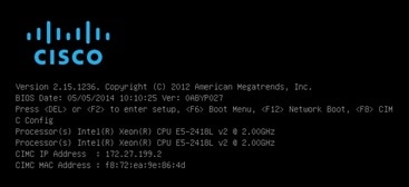
Power On and Initial CIMC Setup
Use this procedure to power on the server and begin basic Cisco Integrated Management controller (CIMC) configuration.
Ensure that the BE6000 server has been rack-mounted, connected to a power supply, connected to the data network, and that a monitor and keyboard are connected to the server, as described in the Quick Start Guide.
What to Do Next
Complete the CIMC Configuration
Use this procedure to configure DNS and NTP settings in the CIMC interface.
Configure ESXi Virtualization Hypervisor
Complete the following tasks to set up ESXi Virtualization Hypervisor.
| Command or Action | Purpose | |
|---|---|---|
| Step 1 | Customize Virtualization Hypervisor Remote Access | Customize your Virtualization Hypervisor to allow remote access using vSphere client. |
| Step 2 | Access and Configure Virtualization Hypervisor | Configure your Virtualization Hypervisor with NTP settings and fault tolerance. |
Customize Virtualization Hypervisor Remote Access
Follow this procedure to customize the Virtualization Hypervisor (VMware vSphere Hypervisor) to enable remote access from your PC using the vSphere client.
Note | For servers ordered via the Config To Order Portal, skip to Step step 5. |
| Step 1 | When the
hypervisor boots, the ESXi Direct Console User Interface displays on the
monitor as shown in the following figure
 |
| Step 2 | Press
F2 to enter the System Customization menu as shown
in the following figure.
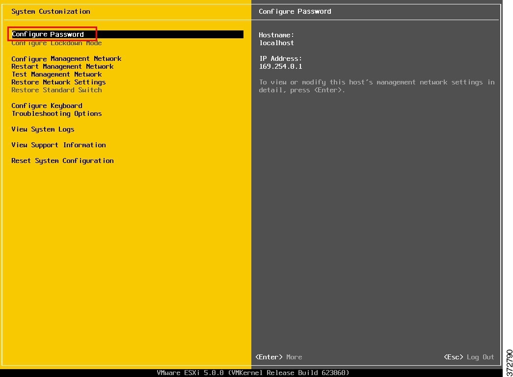 |
| Step 3 | Choose
Configure Password to change the password.
If your applications are preconfigured, skip to Step step 5. |
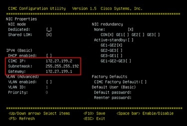
| Step 4 | To assign a
static IP address, select the
Configure Management Network menu, and follow the
instructions on screen to change
"IP
Configuration" as shown in the figure below.
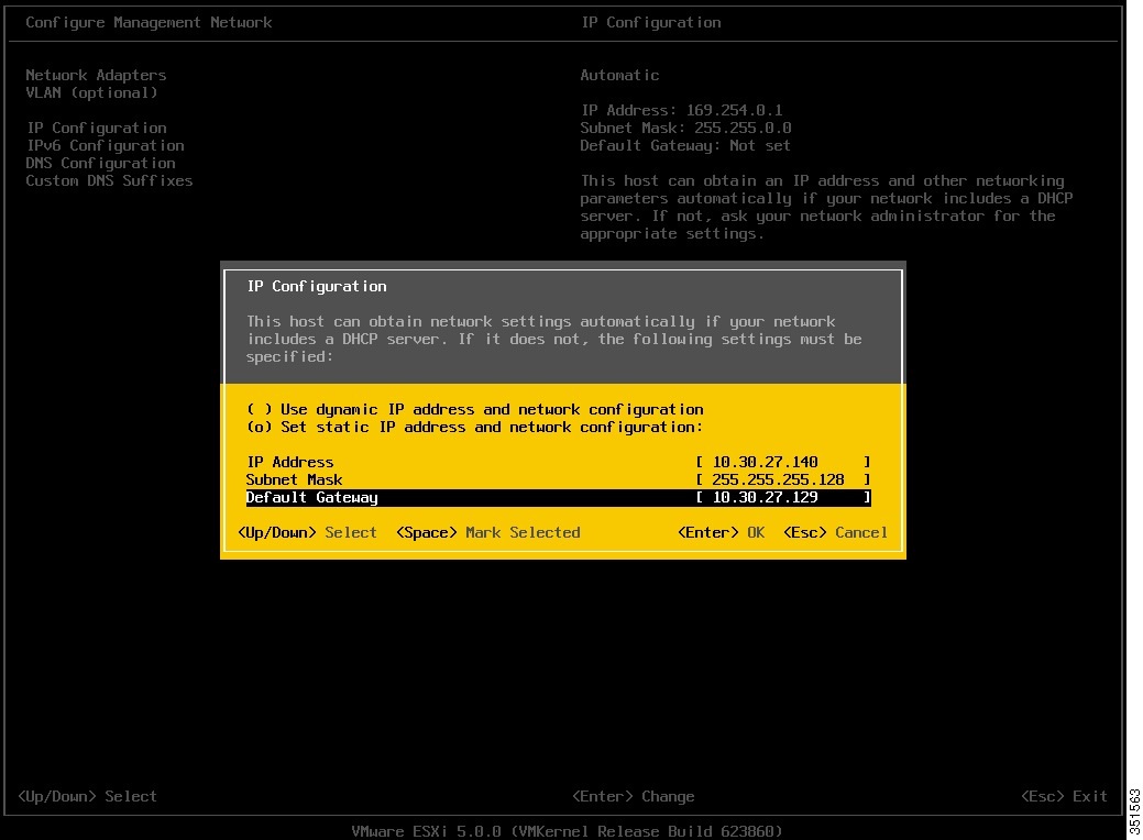 |
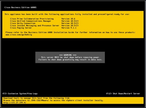
| Step 5 | Connect your
PC to the data network, and browse to the new hypervisor IP address. Verify the
web page as shown in the figure below.
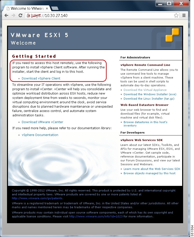 |
| Step 6 | If not already installed on your PC, download and install the vSphere client. The vSphere client can be downloaded from the internet, or accessed in the datastore. |
What to Do Next
Access and Configure Virtualization Hypervisor
Some Business Edition applications require the host to have a valid time reference. Follow these steps to access the ESXi host to configure NTP as well as configure fault tolerance for network interface cards (NICs) using the NIC teaming feature, view preinstalled applications, and browse the datastore to verify the preloaded collaboration application software.
| Step 1 | Launch the
vSphere client application and type the IP address of the Virtualization
Hypervisor.
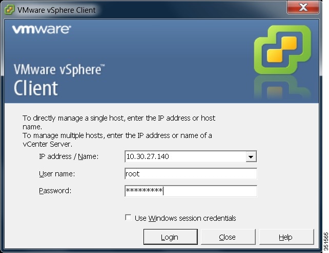 | ||||
| Step 2 | Use the login credentials that you previously configured. | ||||
| Step 3 | (Optional) The
BE6000 Virtualization Hypervisor license is preinstalled and is therefore ready
for use on delivery. If you need to reapply or upgrade the license, follow
these steps:
| ||||
| Step 4 | Configure NTP
settings:
| ||||
| Step 5 | Optional.
Configure fault tolerance by using the NIC teaming feature in VMware:
| ||||
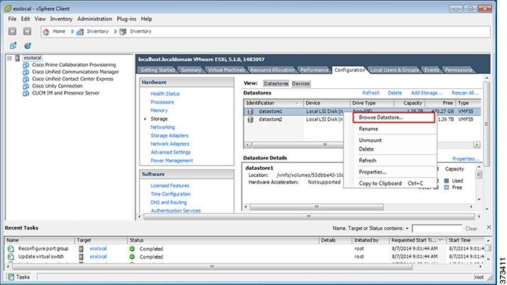
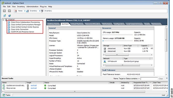
| Step 6 | Browse the
datastore:
 | ||||
| Step 7 | (Optional) Cisco recommends that you archive the OVA-ISO directory locally. If a server fails, the replacement product does not include preloaded content. |
What to Do Next
Delete Unused Pre-configured VMs
If you want a custom install of a pre-configured application, you must delete the pre-configured image before you can install that application. Use this procedure to delete any pre-configured images that you are not using.
Note | If your server was ordered via the Config To Order Portal, you can skip this step as your server does not have pre-configured images. |
What to Do Next
Deploy Virtual Machine OVAs
For each application that you want to install, deploy the appropriate virtual machine OVA file.
For Customized deployments, you must deploy separate VMs for each application. For Pre-configured and Config To Order deployments, you need only deploy VMs for the additional applications that you want to install.
Note | The OVA template file defines the virtual machine for specific applications. OVA templates are deployed in seconds, while a packaged OVA may take longer to deploy. |
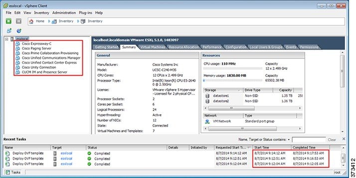
| Step 1 | On the vSphere
Client, navigate to
.
The Deploy OVF Template screen is launched. |
| Step 2 | Browse and select the source OVA template file on your PC. For application and filename mapping, see the Build summaries here: http://www.cisco.com/c/en/us/support/unified-communications/business-edition-6000/products-release-notes-list.html. |
| Step 3 | If prompted to accept license agreements, continue to click Next. |
| Step 4 | Specify a meaningful name for the virtual machine. |
| Step 5 | Select the appropriate virtual machine size for your deployment. |
| Step 6 | Set the remaining parameters, as required. |
| Step 7 | If prompted for the Disk Format, specify Thick Provision Lazy Zero. |
| Step 8 | Deploy VMs for all of your UC applications before proceeding to the next task. |
What to Do Next
If your system includes Cisco Unity Connection, Customize VM for Cisco Unity Connection
Otherwise, Associate Application ISO Files to VM
Customize VM for Cisco Unity Connection
For Customized installations, use this procedure to configure your Cisco Unity Connection virtual machine settings to ensure optimum performance.
For Customized installations of Cisco Unity Connection, you must deploy the VM with high latency sensitivity and configure VM parameters. If the server is a BE6000S, you must also set your resource reservations.
Note | If using two CPUs for Unity Connection, you may need to disable, or not use one of the other supported applications. The total number of CPUs used by active virtual machines must not exceed six. |
What to Do Next
Associate Application ISO Files to VM
If you have deployed a new VM template for any of the following applications, use this procedure to associate the ISO installation files that will be used to complete the installation. Otherwise, you can proceed to the installation tasks.
Cisco Unified Communications Manager
IM and Presence Service
Cisco Unity Connection
Cisco Unified Contact Center Express
Cisco Emergency Responder
Note | For an up to date list of installation files for your server, see the Preload Summary for your server at: http://www.cisco.com/c/en/us/support/unified-communications/business-edition-6000/products-release-notes-list.html |
What to Do Next
Install your UC applications using either of the following procedures:
Install UC Applications Using Touchless Installation
Touchless installation allows you to install multiple UC applications simultaneously, across hosts if required, without having to interact with the system while the install process runs. While you must prepare the system, touchless installation can save time, particularly if you want to install multiple applications. If you are installing only one or two applications, you may prefer to follow the manual procedure in the following section.
Use touchless installation to install the following applications:
| Command or Action | Purpose | |
|---|---|---|
| Step 1 | Generate Answer Files | Generate answer files (AFG files) for UC applications. |
| Step 2 | Create Virtual Floppy Images | Use your AFG files to create virtual floppy images. |
| Step 3 | Upload Virtual Floppy Images to Datastore | Upload your virtual floppy images to the datastore. |
| Step 4 | Mount Virtual Floppy on VM | Mount each virtual floppy on the corresponding UC application VM. |
| Step 5 | Run Touchless Installation | Run the touchless installation of your UC applications. We recommend that you run your installations simultaneously. |
Generate Answer Files
Use this procedure to generate answer files for the touchless installation of your UC applications.
 Tip | We recommend that you create application-specific folders (for example, UCM, IMP, CUC, CCX) in which to save the generated files so that you do not get the files mixed up. |
| Step 1 | Go to the online answer file generator at: www.cisco.com/web/cuc_afg/. |
| Step 2 | From the Product drop-down menu, select the UC application for which you want to generate answer files. |
| Step 3 | Select the Version that you want to install. |
| Step 4 | Complete the remaining fields with the installation details that you want to configure on the server. For example, you can assign items such as passwords, IP addressing, and DNS settings. |
| Step 5 | Click Generate Answer Files to generate the platformConfig.xml file for that UC application. Each UC application generates a platformConfig.xml file. Cisco Unified Communications Manager also generates a clusterConfig.xml file. |
| Step 6 | Save the generated answer files as follows: |
| Step 7 | Repeat these steps for each UC application for which you want to use touchless installation. |
What to Do Next
Create Virtual Floppy Images
Use this procedure to create virtual floppy images from the answer files. You will use the virtual floppy images in your touchless installation.
Tip | We recommend that you follow the recommended naming conventions for your .flp files. |
You can use Winimage to create the virtual floppy images. You can download Winimage from http://www.winimage.com/download.htm. You can also use other tools, such as BFI, to create virtual floppy images.
What to Do Next
Upload Virtual Floppy Images to Datastore
Use this procedure to upload the virtual floppy images to the datastore.
What to Do Next
Mount Virtual Floppy on VM
Use this procedure to mount the UC application virtual floppy images on their corresponding VM.
What to Do Next
Run Touchless Installation
What to Do Next
Use the manual method to install any remaining UC applications:
Install UC Applications Manually
Use this procedure to follow the interactive install process to install any UC applications that do not have a touchless install option such as Cisco Emergency Responder.
Note | For details specific to Cisco Prime Collaboration Provisioning or Cisco TelePresence Video Communications Server installations, refer to: |
Note | If you want to use this method to install both Cisco Unified Communications Manager and IM and Presence Service, you must first complete installation of the Unified Communications Manager publisher. |
Complete Packed Virtual Machine (OVA) Installation
- Complete Prime Collaboration Provisioning Installation
- Complete Cisco Video Communications Server Installation
Complete Prime Collaboration Provisioning Installation
Use this procedure to complete installation of Cisco Prime Collaboration Provisioning.
Complete Cisco Video Communications Server Installation
Use this procedure to complete installation of Cisco Video Communications Server.
Note | For detailed documentation on installing and setting up Cisco Video Communication Server, refer to http://www.cisco.com/c/en/us/support/unified-communications/telepresence-video-communication-server-vcs/products-installation-guides-list.html. |
 Feedback