Your Analog Telephone Adapter
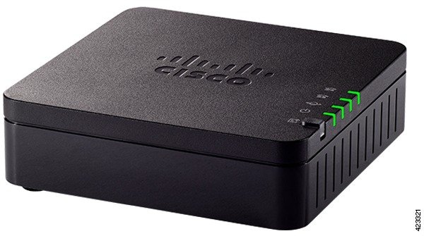
The ATA 191 and ATA 192 analog telephone adapters are telephony-device-to-Ethernet adapters that allow regular analog phones to operate on IP-based telephony networks. Both models support two voice ports, each with an independent phone number. Both have an RJ-45 10/100BASE-T data port while the ATA 192 has an additional Ethernet port.
The ATA connects to the Internet through a broadband (DSL or cable) modem or router. The ATA can be used with an on-site call-control system or an Internet-based call-control system.
The ATA is an intelligent low-density Voice over IP (VoIP) gateway that enables carrier-class residential and business IP Telephony services delivered over broadband or high-speed Internet connections. An ATA maintains the state of each call it terminates and reacts appropriately to user input events (such as on/off hook or hook flash). The ATAs use the Session Initiation Protocol (SIP) open standard so there is on/off hook or hook flash. The ATAs use the Session Initiation Protocol (SIP) open standard so there is little or no involvement by a “middle-man” server or media gateway controller. SIP allows inter-operation with all ITSPs that support SIP.
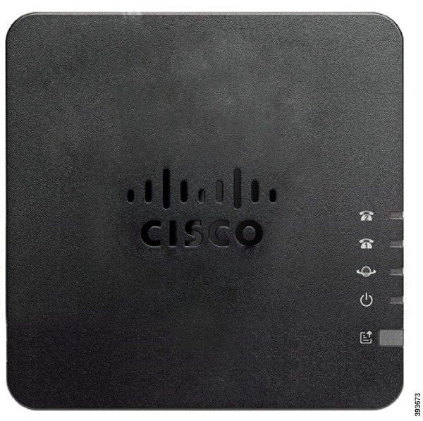
ATA 191 and ATA 192 Top Panel
The following figure shows the different LEDs and buttons found on the top of your ATA.
|
Item |
Description |
||
|---|---|---|---|
|
Power LED
|
Steady green: System booted up successfully and is ready for use. Slow flashing green: System is booting up. Fast flashing green three times, then repeats: System failed to boot up. Fast flashing green: The LED behaviour occurs in the following situations:
Off: Power is off. |
||
|
Network LED
|
Flashing green: Data transmission or reception is in progress through the WAN port. Off: No link. |
||
|
Phone 1 LED Phone 2 LED
|
Steady green: On hook. Slow flashing green: Off hook. Fast flashing green three times, then repeats: The analog device failed to register. Fast flashing green: A factory reset is performed successfully. Off: The port is not configured. |
||
|
Problem Report Tool (PRT) Button
|
Press this button to create a problem report using the Problem Report Tool.
|
||
|
Problem Report Tool (PRT) LED
|
Flashing amber: The PRT is preparing the data for the problem report. Fast Flashing amber: The PRT is sending the problem report log to the HTTP server. Solid amber: The activation of the FIPS mode failed. Press the PRT button to turn off the PRT LED. Solid green for five seconds, then off: The PRT report was sent successfully. Fast flashing green: A factory reset is performed successfully. Flashing red: The PRT report failed. Press the PRT button once to cancel the flashing, then press again to trigger a new PRT. |


Problem Report Tool Button
The Problem Report Tool (PRT) button is on the ATA top panel. Press the PRT button, and a log file is prepared and uploaded to the server for troubleshooting your network.
You can instruct your analog phone users to press the PRT button on the ATA device to start the PRT log file process.
-
Set up the HTTP server to upload the PRT log file from the ATA.
-
Configure the customer support upload URL to best suit your needs, and apply it to the ATA.
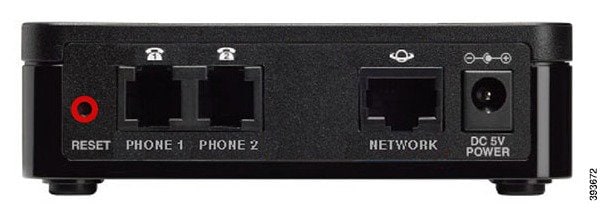
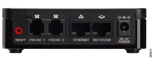
ATA 191 and ATA 192 Back Panel
The following figures shows the different ports and buttons found on the back of your ATA.
|
Item |
Description |
|---|---|
|
RESET |
To restart the ATA, use a paper clip or similar object to press this button briefly. To restore the factory default settings, press and hold for about 10 seconds. The LED behaviour for the factory reset:
|
|
PHONE 1 |
Use an RJ-11 phone cable to connect an analog phone or fax machine. |
|
PHONE 2 |
Use an RJ-11 phone cable to connect a second analog phone or fax machine. |
|
ETHERNET (ATA 192 only) |
Use an Ethernet cable to connect your ATA to a device on your network, such as a computer. |
|
NETWORK |
Use an Ethernet cable to connect to the network. |
|
DC 5V POWER |
Use the power adapter that was provided to connect to a power source. |
 Feedback