- Overview of Cisco Analog Video Gateway Software Installation
- Installing Cisco Analog Video Gateway Module on a New System
- Upgrading Software Using the Online Installer (No Backup and Restore Required)
- Installing Software Using the Boot Helper
- Backing Up Files
- Restoring Files
- Verifying Cisco IP Video Surveillance Installation
- Index
- Cisco IPVS MJPEG Video Viewer
- RS-485 Interface
- Contact Closure and Alarm Interface
- Configuring Video Port Events Using the Applet Tool
Appendix C: Verifying Cisco IPVS Installation and Configuring Video Port Events
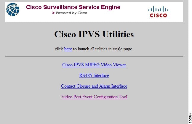
The Cisco IP Video Surveillance (Cisco IPVS) Utilities, made up of Java applets, provide graphical user interface (GUI) tools used to verify the installation parameters, as well as to configure video port alarm events on the Cisco Analog Video Gateway network module.
Log into the IPVS Video Viewer using your username (default username: admin) and password. From the Cisco IPVS welcome window (see Figure 1), click on the first three options separately to verify the streaming video setup, RS-485 setup, and contact closure and alarm interface setup parameters. Click the fourth option to configure video port alarm events.
•![]() Cisco IPVS MJPEG Video Viewer
Cisco IPVS MJPEG Video Viewer
•![]() Contact Closure and Alarm Interface
Contact Closure and Alarm Interface
•![]() Configuring Video Port Events Using the Applet Tool
Configuring Video Port Events Using the Applet Tool
Figure 1 Cisco IPVS Utilities Welcome Window
Cisco IPVS MJPEG Video Viewer
To verify individual camera installations or your streaming video setup, complete the following steps:
Step 1 ![]() From the Cisco IPVS Utilities welcome window (Figure 1), click the Cisco IPVS MJPEG Video Viewer link.
From the Cisco IPVS Utilities welcome window (Figure 1), click the Cisco IPVS MJPEG Video Viewer link.
The Cisco IPVS Video Viewer window (Figure 2) appears.
Figure 2 Cisco IPVS MJPEG Video Viewer Window
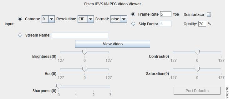
Step 2 ![]() Select either the Camera video port number from the drop-down menu or enter the Stream Name and then set the following input parameters:
Select either the Camera video port number from the drop-down menu or enter the Stream Name and then set the following input parameters:

Note ![]() A valid video signal must exist on the port before the sliders are enabled. The color bar cannot be changed because it is generated by the DSP.
A valid video signal must exist on the port before the sliders are enabled. The color bar cannot be changed because it is generated by the DSP.
•![]() Camera drop-down list field—Selects the specific camera video port (0-15) to be used for the test.
Camera drop-down list field—Selects the specific camera video port (0-15) to be used for the test.
–![]() Resolution drop-down list field—Sets the resolution (CIF or 4CIF) for the specified camera.
Resolution drop-down list field—Sets the resolution (CIF or 4CIF) for the specified camera.
–![]() Format drop-down list field—Sets the camera format (NTSC or PAL) for the specified camera.
Format drop-down list field—Sets the camera format (NTSC or PAL) for the specified camera.
–![]() Frame Rate or Skip Factor field—Sets the frame rate or skip factor for the specified camera.
Frame Rate or Skip Factor field—Sets the frame rate or skip factor for the specified camera.
–![]() Deinterlace checkbox—Enables (when checked) or disables (when unchecked) the deinterlace for the specified camera.
Deinterlace checkbox—Enables (when checked) or disables (when unchecked) the deinterlace for the specified camera.
–![]() Picture quality—Sets the image quality as a percentage for the specified camera.
Picture quality—Sets the image quality as a percentage for the specified camera.
•![]() Stream Name—Enter the video stream name for the video stream profile that you have configured.
Stream Name—Enter the video stream name for the video stream profile that you have configured.
Note![]() •
•![]() The name entered in the Stream Name field must already exist on the Cisco Analog Video Gateway application; that is, the Stream Name must have been previously configured using the CLI.
The name entered in the Stream Name field must already exist on the Cisco Analog Video Gateway application; that is, the Stream Name must have been previously configured using the CLI.
•![]() When the Stream Name is selected, the video parameter adjustment sliders are disabled.
When the Stream Name is selected, the video parameter adjustment sliders are disabled.
•![]() If you change the stream profile, the new Stream Name must match the name of the new stream profile.
If you change the stream profile, the new Stream Name must match the name of the new stream profile.
Step 3 ![]() Select the camera video port and click View Video.
Select the camera video port and click View Video.
•![]() If the camera video port is selected and the camera parameters are properly configured, the video appears in the lower area of the window.
If the camera video port is selected and the camera parameters are properly configured, the video appears in the lower area of the window.
•![]() If a video Stream Name is selected and the streaming video profile name is correct, the streaming video appears when you click Play (you can also Pause and Stop the streaming video).
If a video Stream Name is selected and the streaming video profile name is correct, the streaming video appears when you click Play (you can also Pause and Stop the streaming video).
Step 4 ![]() Use the slider to adjust the following video parameters. The new parameter values are immediately and automatically saved to the Cisco Analog Video Gateway application and reflected in the video stream within moments.
Use the slider to adjust the following video parameters. The new parameter values are immediately and automatically saved to the Cisco Analog Video Gateway application and reflected in the video stream within moments.
Note ![]() Click and drag the slider to set the parameter value within the ranges shown. The slider will only send changes to the Cisco Analog Video Gateway application upon the release of the mouse button after the slider is in the chosen position.
Click and drag the slider to set the parameter value within the ranges shown. The slider will only send changes to the Cisco Analog Video Gateway application upon the release of the mouse button after the slider is in the chosen position.
•![]() Brightness (0)—Adjust the video brightness in the range of -127 to +127. The default brightness value is set at zero.
Brightness (0)—Adjust the video brightness in the range of -127 to +127. The default brightness value is set at zero.
•![]() Hue (0)—Adjust the video hue in the range of -127 to +127. The default hue value is set at zero.
Hue (0)—Adjust the video hue in the range of -127 to +127. The default hue value is set at zero.
•![]() Sharpness (0)—Adjust the video sharpness in the range of 0 to +3. The default sharpness value is set at zero.
Sharpness (0)—Adjust the video sharpness in the range of 0 to +3. The default sharpness value is set at zero.
•![]() Contrast (0)—Adjust the video contrast in the range of -127 to +127. The default contrast value is set at zero.
Contrast (0)—Adjust the video contrast in the range of -127 to +127. The default contrast value is set at zero.
•![]() Saturation (0)—Adjust the video saturation in the range of -127 to +127. The default saturation value is set at zero.
Saturation (0)—Adjust the video saturation in the range of -127 to +127. The default saturation value is set at zero.
Step 5 ![]() Click Port Defaults to reset the video parameters to their default values.
Click Port Defaults to reset the video parameters to their default values.
RS-485 Interface
To verify your RS-485 setup, complete the following steps:
Step 1 ![]() From the Cisco IPVS Utilities welcome window (Figure 1), click the RS-485 Interface link.
From the Cisco IPVS Utilities welcome window (Figure 1), click the RS-485 Interface link.
The RS-485 Control window (Figure 3) appears.
Figure 3 RS-485 Control Window
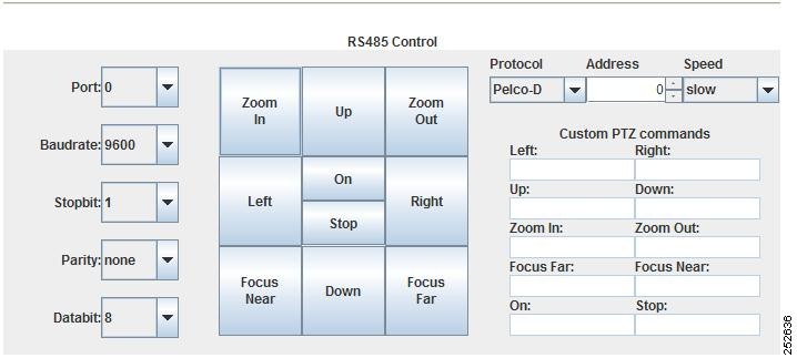
Step 2 ![]() Verify the port-related values shown in the drop-down list for the following parameters:
Verify the port-related values shown in the drop-down list for the following parameters:
•![]() Port number (0 or 1) for the interface connection.
Port number (0 or 1) for the interface connection.
Note ![]() If you change the port number, the values displayed will update to reflect the configuration of the newly selected port number.
If you change the port number, the values displayed will update to reflect the configuration of the newly selected port number.
•![]() Baud rate drop-down list field—Displays the baud rate (1200, 2400, 4800, 9600, 19200, 38400, 57600, or 115200) setting.
Baud rate drop-down list field—Displays the baud rate (1200, 2400, 4800, 9600, 19200, 38400, 57600, or 115200) setting.
•![]() Stop bit drop-down list field—Displays the stop bit (1, 1.5, or 2) setting.
Stop bit drop-down list field—Displays the stop bit (1, 1.5, or 2) setting.
•![]() Parity drop-down list field—Displays the parity (even, none, or odd) setting.
Parity drop-down list field—Displays the parity (even, none, or odd) setting.
•![]() Data bit drop-down list field—Displays the data bit (5, 6, 7, or 8) setting.
Data bit drop-down list field—Displays the data bit (5, 6, 7, or 8) setting.
Step 3 ![]() Verify the camera-related values for the following parameters:
Verify the camera-related values for the following parameters:
•![]() Protocol drop-down list field—Displays the protocol (Pelco-ID or Custom) setting. For Custom, enter your specific pan-tilt-zoom (PTZ) custom commands.
Protocol drop-down list field—Displays the protocol (Pelco-ID or Custom) setting. For Custom, enter your specific pan-tilt-zoom (PTZ) custom commands.
•![]() Address field—Displays the device (device ID) address setting.
Address field—Displays the device (device ID) address setting.
•![]() Speed drop-down list field—Displays the camera speed (slow, medium, or fast). Camera speed determines how fast the camera moves when a pan, tilt, or zoom command is issued.
Speed drop-down list field—Displays the camera speed (slow, medium, or fast). Camera speed determines how fast the camera moves when a pan, tilt, or zoom command is issued.
Step 4 ![]() Verify the proper operation of the following camera controls:
Verify the proper operation of the following camera controls:
•![]() Custom PTZ commands.
Custom PTZ commands.
•![]() Control the image view by using the center panel command buttons, such as Zoom In, Zoom Out, Left, Right, and so on.
Control the image view by using the center panel command buttons, such as Zoom In, Zoom Out, Left, Right, and so on.
Contact Closure and Alarm Interface
To verify the Cisco IPVS video port LED status, contact closures, and alarm monitors, complete the following steps:
Step 1 ![]() From the Cisco IPVS Utilities welcome window (Figure 1), click the Contact Closure and Alarm Interface link.
From the Cisco IPVS Utilities welcome window (Figure 1), click the Contact Closure and Alarm Interface link.
The Video Port LED Status, Contact Closure, and Alarm Monitor window (Figure 4) appears.
Figure 4 Video Port LED Status, Contact Closure, and Alarm Window
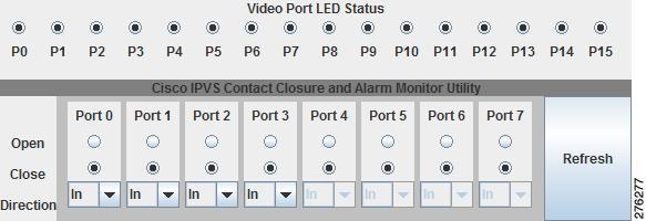
Step 2 ![]() Video Port Status LED—Displays the video port LED status for ports P0 to P15 display. The darkened circle indicates that the LED is ON.
Video Port Status LED—Displays the video port LED status for ports P0 to P15 display. The darkened circle indicates that the LED is ON.
Step 3 ![]() To view the status of the contact closure port inputs or to change contact closure port outputs, use the following guidelines. Changing the contact closure setup through this graphical interface changes the configuration setup of the contact closure ports.
To view the status of the contact closure port inputs or to change contact closure port outputs, use the following guidelines. Changing the contact closure setup through this graphical interface changes the configuration setup of the contact closure ports.
Note ![]() There are eight contact closure interfaces. The first four can be configured as alarm inputs or relay outputs. The remaining four are for inputs only.
There are eight contact closure interfaces. The first four can be configured as alarm inputs or relay outputs. The remaining four are for inputs only.
•![]() When the contact closure is an input (Direction > In to indicate a contact closure input port), only the status is displayed for ports 0 to 7.
When the contact closure is an input (Direction > In to indicate a contact closure input port), only the status is displayed for ports 0 to 7.
•![]() When the contact closure is an output (Direction > Out to indicate a contact closure output port), you can set the contact closure to either the Open or Closed position by first selection Out using the Direction drop-down menu, and then clicking on the port's corresponding radio button. When setting a contact output, be sure to click Refresh to view the updated status of the contact closure state. A darkened circle indicates the contact closure state.
When the contact closure is an output (Direction > Out to indicate a contact closure output port), you can set the contact closure to either the Open or Closed position by first selection Out using the Direction drop-down menu, and then clicking on the port's corresponding radio button. When setting a contact output, be sure to click Refresh to view the updated status of the contact closure state. A darkened circle indicates the contact closure state.
Step 4 ![]() Click Refresh to update the contact closure display.
Click Refresh to update the contact closure display.
Configuring Video Port Events Using the Applet Tool
The Video Port Event Configuration Applet tool configures and tests the initial setup of the Cisco Analog Video Gateway network module. The applet allows you to add, modify, and delete video port alarm profiles stored in the Cisco Analog Video Gateway module.
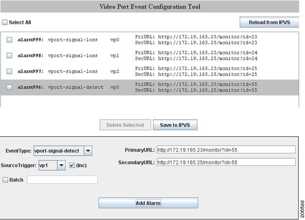
From the Cisco IPVS Utilities welcome window (Figure 1), click the Video Port Event Configuration Tool link. The Video Port Event Configuration Tool window (Figure 5) appears. Proceed to the following sections to configure video port alarm profiles:
•![]() Configuring Alarm Profiles and Profile Summaries
Configuring Alarm Profiles and Profile Summaries
•![]() Adding, Modifying, and Deleting Alarm Profiles
Adding, Modifying, and Deleting Alarm Profiles
•![]() Example: Setting Alarms to Be Reported to the Cisco Video Management and Storage System
Example: Setting Alarms to Be Reported to the Cisco Video Management and Storage System
Using the Applet Tool GUI
There are two main window panes (see Figure 5) of the applet tool graphical user interface (GUI):
•![]() Alarm profile (top) pane—contains the current list of alarm profiles
Alarm profile (top) pane—contains the current list of alarm profiles
•![]() Configuration (bottom) pane—used to configure the alarm profiles, such as adding and modifying profiles, using the drop-down menus
Configuration (bottom) pane—used to configure the alarm profiles, such as adding and modifying profiles, using the drop-down menus
The alarm profile list is initially populated with the profiles loaded from the Cisco Analog Video Gateway application. As changes are made, those new added profiles or existing profiles that have been modified are shown in gray (Figure 5). Within these two panes, there are four buttons:
•![]() Save to IPVS—stores the current profile list to the Cisco Analog Video Gateway application. This button is only enabled when changes occur—such as adding a new profile, modifying an existing profile, or deleting an existing profile—that need to be saved.
Save to IPVS—stores the current profile list to the Cisco Analog Video Gateway application. This button is only enabled when changes occur—such as adding a new profile, modifying an existing profile, or deleting an existing profile—that need to be saved.
•![]() Reload from IPVS—discards the current profile list and reloads the configuration stored on the Cisco Analog Video Gateway application.
Reload from IPVS—discards the current profile list and reloads the configuration stored on the Cisco Analog Video Gateway application.
•![]() Delete Selected—deletes all profiles that have their checkboxes selected. If none of the checkboxes are selected, the button is disabled.
Delete Selected—deletes all profiles that have their checkboxes selected. If none of the checkboxes are selected, the button is disabled.
•![]() Add Alarm—adds a new alarm after the alarm parameters are configured.
Add Alarm—adds a new alarm after the alarm parameters are configured.
Figure 5 Video Port Event Configuration Tool: Top and Bottom Panes
Configuring Alarm Profiles and Profile Summaries
Alarm monitor profiles configured on the Cisco Analog Video Gateway are made up of three profiles:
•![]() Destination-profile—defines primary and secondary URLs that are triggered in the case where an alarm event occurs
Destination-profile—defines primary and secondary URLs that are triggered in the case where an alarm event occurs
•![]() Monitor-profile—identifies the EventType (for example, video-loss) and SourceTrigger (for example, video port 0)
Monitor-profile—identifies the EventType (for example, video-loss) and SourceTrigger (for example, video port 0)
•![]() Notifier-profile—connects a monitor (input) with a destination (output)
Notifier-profile—connects a monitor (input) with a destination (output)
The following are examples of alarm monitor profile configurations:
alarm-monitor destination-profile dest999
primaryURL "http://172.19.165.23/monitor?id=23"
secondaryURL "http://172.19.165.25/monitor?id=23"
alarm-monitor monitor-profile mon999
event vport-signal-loss
sourceTrigger vp0
alarm-monitor notifier-profile not999
destinationProfileTag dest999
monitorProfileTag mon999
The applet tool combines these three alarm monitor profiles into one summary profile called an alarm profile. The following is an example of an alarm profile:
alarm999: vport-signal-loss vp0 PriURL: http://172.19.165.23/monitor?id=23
SecURL: http://172.19.165.25/monitor?id=23
You do not need to manage all three destination-profile, monitor-profile, and notifier-profile configurations separately because the applet manages these profiles for you in the background.
When the applet starts, it reads the current configuration from the Cisco Analog Video Gateway module and summarizes the configurations into alarm profiles, populating them in an alarm profile list. The list changes as you add, delete, and modify the profiles. When the Save to IPVS button is clicked, the applet writes the new configurations to the Cisco Analog Video Gateway module, expanding the alarm profile to their individual destination-profile, monitor-profile, and notifier-profile configurations.
Adding, Modifying, and Deleting Alarm Profiles
Use the following procedures to add, modify, or delete an alarm profile.
Adding New Alarm Profiles
To add a new alarm profile:
Step 1 ![]() From the drop-down menu in the configuration pane, select the desired EventType and SourceTrigger.
From the drop-down menu in the configuration pane, select the desired EventType and SourceTrigger.
Step 2 ![]() Enter the primary URL in the PrimaryURL field (see Note).
Enter the primary URL in the PrimaryURL field (see Note).
Step 3 ![]() Enter the secondary URL in the SecondaryURL field (see Note).
Enter the secondary URL in the SecondaryURL field (see Note).
Step 4 ![]() Click the Add Alarm button.
Click the Add Alarm button.
Note ![]() The URL field entries must satisfy the following rules:
The URL field entries must satisfy the following rules:
•![]() At least one of the URLs has to be non-empty.
At least one of the URLs has to be non-empty.
•![]() A non-empty URL field has to start with "http://" plus at least one more character (for example, "http://a").
A non-empty URL field has to start with "http://" plus at least one more character (for example, "http://a").
For convenience, an auto-increment mode can be enabled by selecting the (Inc) checkbox. When this checkbox is selected, the SourceTrigger automatically increments by one (until "vp15" is reached) every time the Add Alarm button is clicked.
Additionally, a batch mode and URL string macros are supported (for more information, see "Using the Batch Mode" section and "Using URL Macros" section).
Modifying Alarm Profiles
To modify an existing alarm profile:
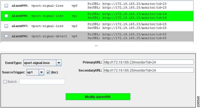
Step 1 ![]() Click on the profile to be modified in the alarm profile pane (see Figure 6).
Click on the profile to be modified in the alarm profile pane (see Figure 6).
The selected profile (shown in green) is then highlighted, and its values populated in the configuration pane.
Note ![]() Modifications to alarm profiles cannot be undone once the modifications take effect; a modified alarm configuration cannot be reverted to its previous configuration.
Modifications to alarm profiles cannot be undone once the modifications take effect; a modified alarm configuration cannot be reverted to its previous configuration.
Step 2 ![]() Modify the values using the EventType and SourceTrigger drop-down menus and URL fields in the configuration pane.
Modify the values using the EventType and SourceTrigger drop-down menus and URL fields in the configuration pane.
To cancel out of the modified profile, click on the same alarm line (shown in green) once more or click on a different alarm profile.
Step 3 ![]() Click on the Modify alarmnnn button, where nnn is the alarm number, to save your changes.
Click on the Modify alarmnnn button, where nnn is the alarm number, to save your changes.
Figure 6 Modifying Alarm Profiles
Deleting Alarm Profiles
To delete one or more alarm profiles:
Step 1 ![]() In the alarm profile pane, select the checkboxes of the profiles you want to delete.
In the alarm profile pane, select the checkboxes of the profiles you want to delete.
Note ![]() Modifications to alarm profiles cannot be undone once the modifications take effect; a modified configuration cannot be reverted to its previous configuration.
Modifications to alarm profiles cannot be undone once the modifications take effect; a modified configuration cannot be reverted to its previous configuration.
Step 2 ![]() Click Delete Selected, to delete the alarm profiles that have the checkboxes selected.
Click Delete Selected, to delete the alarm profiles that have the checkboxes selected.
Using the Batch Mode
The batch mode allows you to quickly generate a set of alarm profiles that share the same EventType and destination URLs but use different SourceTriggers.
To set the batch mode:
Step 1 ![]() Click the checkbox next to the Batch text field (see Figure 7) to enable batch mode.
Click the checkbox next to the Batch text field (see Figure 7) to enable batch mode.
This disables the SourceTrigger drop-down menus and enables the Batch text field.
Step 2 ![]() Enter a series of SourceTriggers, separated by commas.
Enter a series of SourceTriggers, separated by commas.
For example, the format of the Batch field is {<VP>,[<VP>, ...]}, where VP is either an individual video port (such as "vp3") or a range of video ports (such as "vp5-10").
Step 3 ![]() Click the Add Alarm button.
Click the Add Alarm button.
The applet generates a new profile for each SourceTrigger in the alarm profile list while using the same EventType and destination URLs (except for when URL macros are used).
Figure 7 is an example alarm profile list generated using the batch mode string of "vp1, vp4-6, vp10, vp14-15" and then clicking the Add Alarm button once.
Figure 7 Batch Mode Example

Using URL Macros
Macros allow you to dynamically generate URLs by inserting either the current video port number or an incremental counter at any position in the URL. A macro is identified by special characters and parentheses. They can be in any one of the following formats and entered into the PrimaryURL and SecondaryURL fields (see Figure 8 for an example of where the macro characters are inserted):
•![]() (#)—inserts the current port number (for example, vp3, where video port number is 3)
(#)—inserts the current port number (for example, vp3, where video port number is 3)
•![]() (#±offset)—inserts the current video port number adjusted by a positive or negative offset, where the offset is a valid integer value
(#±offset)—inserts the current video port number adjusted by a positive or negative offset, where the offset is a valid integer value
•![]() (%)—when in batch mode only, inserts the value of an incremental counter that starts at 0
(%)—when in batch mode only, inserts the value of an incremental counter that starts at 0
•![]() (%±offset)—inserts the value of an incremental counter adjusted by a positive or negative offset, where the offset is a valid integer value
(%±offset)—inserts the value of an incremental counter adjusted by a positive or negative offset, where the offset is a valid integer value
Macros can be used with or without batch mode enabled. When batch mode is disabled, the (%) macro always results in a 0 integer value.
Figure 8 is an example of dynamically generating URLs by inserting either the current video port number or an incremental counter at any position in the URL with the batch mode disabled. In this example:
•![]() Event is "vport-signal-detect"
Event is "vport-signal-detect"
•![]() SourceTrigger is "vp5"
SourceTrigger is "vp5"
•![]() PrimaryURL is "http://172.19.165.25/monitor?id=(#-3)"
PrimaryURL is "http://172.19.165.25/monitor?id=(#-3)"
•![]() SecondaryURL is "http://172.19.165.25/monitor?id=(%+5)"
SecondaryURL is "http://172.19.165.25/monitor?id=(%+5)"
With a SourceTrigger of "vp5," the (#-3) macro in the PrimaryURL is interpreted as "2" (5-3), while the (%+5) in the SecondaryURL is interpreted as 5 (0+5).
Figure 8 URL Macro Example with Batch Mode Disabled
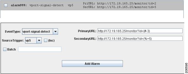
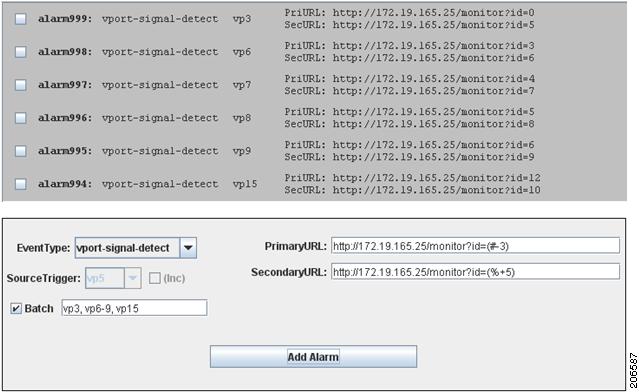
Figure 9 is an example of dynamically generating URLs by inserting either the current video port number or an incremental counter at any position in the URL with the batch mode enabled. In this example:
•![]() Event is "vport-signal-detect"
Event is "vport-signal-detect"
•![]() SourceTrigger is "vp3, vp6-9, vp15"
SourceTrigger is "vp3, vp6-9, vp15"
•![]() PrimaryURL is "http://172.19.165.25/monitor?id=(#-3)"
PrimaryURL is "http://172.19.165.25/monitor?id=(#-3)"
•![]() SecondaryURL is "http://172.19.165.25/monitor?id=(%+5)"
SecondaryURL is "http://172.19.165.25/monitor?id=(%+5)"
The Batch field in this example expands to a total of six SourceTriggers: vp3, vp6, vp7, vp8, vp9, and vp15. The port numbers used in the "#" macro are {3, 6, 7, 8, 9, 15}, so that (#-3) is {0, 3, 4, 5, 6, 12}.
The counter (%) runs from {0...6}, so that (%+5)={5, 6, 7, 8, 9, 10}.
Figure 9 URL Macro Example with Batch Mode Enabled
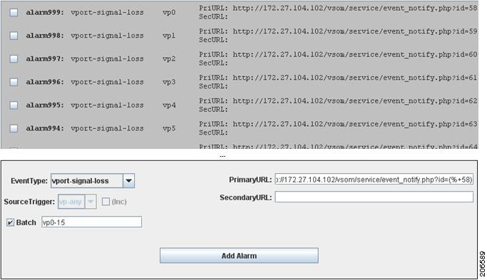
Example: Setting Alarms to Be Reported to the Cisco Video Management and Storage System
In this example, it is assumed that alarm events are set to report the loss of video on all 16 ports of the Cisco Analog Video Gateway module. On the Cisco Video Management and Storage System module, 16 soft trigger events are created that follow the general format:
http://<ip-address>/vsom/service/event_notify.php?id=<ID>
The ID runs from {58...73} as shown in the following specific example:
http://172.27.104.102/vsom/service/event_notify.php?id=58
http://172.27.104.102/vsom/service/event_notify.php?id=59
http://172.27.104.102/vsom/service/event_notify.php?id=60
.
.
.
http://172.27.104.102/vsom/service/event_notify.php?id=73
On the applet tool (see Figure 10), 16 corresponding alarm profiles are generated using the following configuration and clicking Add Alarm once:
•![]() Event is "vport-signal-loss"
Event is "vport-signal-loss"
•![]() SourceTrigger is "vp0-15"
SourceTrigger is "vp0-15"
•![]() PrimaryURLis "http://172.27.104.102/vsom/service/event_notify.php?id=(%+58)"
PrimaryURLis "http://172.27.104.102/vsom/service/event_notify.php?id=(%+58)"
Figure 10 URL Macro Example with Batch Mode Enabled
 Feedback