Overview
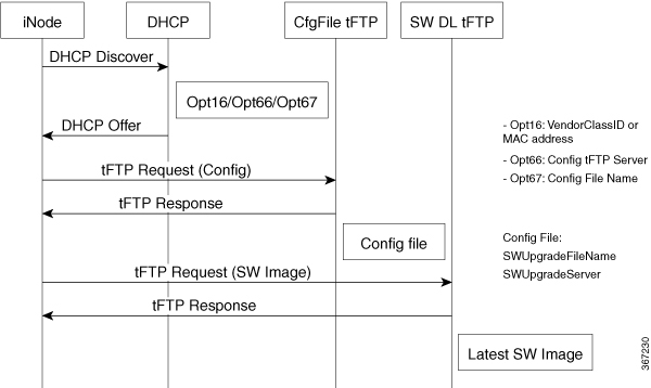
The methods used for triggering and transferring software images are initiated and completed in a manner similar to a cable modem software download. There are two ways to trigger the software upgrade. The first method involves an automatic software upgrade during boot-up of the iNode. The second method includes a planned upgrade of one or more iNodes, using the SNMP SCTE-HMS-COMMON-MIB commonReset to initiate a warm reboot. With either method, upon boot-up a software upgrade is started.
The iNode contains two memory partitions for holding a Primary and Secondary software image. A new image will be downloaded into the partition marked as Secondary if the upgrade image name in the inode.cfg file is not currently loaded in either partition. After the download operation has successfully completed, the partition containing the desired software image is marked as the Primary partition and the iNode is rebooted into that partition.
The downloaded image is a monolithic image that contains the Linux Kernel and the Root File System needed to upgrade the iNode. Prior to release, the monolithic image is signed with the Cisco digital signature. Signatures are used for image validation prior to installation on the iNode. Following validation, and only if the specified image does not already exist on the iNode, the image is downloaded to flash memory. If for any reason the download fails, the current working image continues to execute on the iNode.
Each time the iNode boots a “boot counter” is incremented. The “boot counter” is reset when a successful Software Download operation has been completed. If the iNode is in a cyclic reset condition where the “boot counter” reaches a limit of 7 boot attempts the U-Boot module will revert the Secondary partition to a Primary partition state and mark the current partition as defective. This is a “fall-back” feature to ensure the iNode is able to boot correctly and recover from a defective image.


 Feedback