- Preface
- New and Changed Information for this Release
- Overview
- Managing VMware Clouds
- VMware VM Provisioning
- Managing VMware Content Libraries
- Managing VMware Templates
- VM Provisioning Using ISO Images
- Managing VMware Linked Clones
- Managing VMware Datastore Clusters
- Managing Virtual SAN Clusters
- Managing VMware Host Profiles
- Managing VMkernel NICs
- Managing VMware vMotion
- Enabling VMware Remote Console
- Managing VMware Distributed Resource Scheduler
- Managing VM Annotations
- Managing VMware vCenter Site Recovery Manager
- Managing Cisco Virtual Machine Fabric Extender For VMware
- Appendix
Managing VMware
vCenter Site Recovery Manager
This chapter contains the following sections:
- About VMware vCenter Site Recovery Manager
- Overview of SRM Configuration
- Integrating SRM with Cisco UCS Director
About VMware vCenter Site Recovery Manager
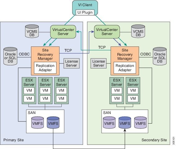
VMware vCenter Site Recovery Manager (SRM) is a business continuity and disaster recovery solution that helps you to plan, test, and run the recovery of virtual machines between a protected vCenter Server site and a recovery vCenter Server site. The following terms are important for fully understanding SRM technology.
- Array-based replication (ABR)
-
Replication of virtual machines that is managed and executed by the storage subsystem itself, rather than from inside the virtual machines, the vmkernel or the Service Console.
- Failback
-
Reversal of direction of replication, and automatic reprotection of protection groups.
- Failover
-
Event that occurs when the recovery site takes over operation in place of the protected site after the declaration of a disaster.
- Protection group
-
A group of virtual machines that will be failed over together to the recovery site during testing or recovery.
- Protected site
-
The primary site that contains the virtual machines to be protected.
- Recovery site
-
The secondary site to which virtual machines will fail over.
Overview of SRM Configuration
Configuring SRM after installation on the protected and recovery site involves the following steps:
-
Configure array managers in SRM: Array managers are identities of the storage systems at both the protected and recovery sites. Once SRM is installed, it interrogates the array managers and discovers which datastores have been marked for replication.
-
Define inventory mappings: Inventory mappings build a relationship between the folders, resource pools and networks between the protected site and recovery site. These mappings ensure that VMs are recovered to the correct location in the vCenter environment.
-
Create protection groups: Protection Groups are pointers to the replicated vSphere datastores that contain collections of virtual machines that will be failed over from the protected site to the recovery site.
-
Create recovery plans: A recovery plan is like an automated runbook. It controls every step of the recovery process, including the order in which virtual machines are powered off or powered on, the network addresses that recovered virtual machines use, and so on. A recovery plan applies to one or more protection groups. The protection groups use the inventory mappings to determine the location of placeholder VMs. These placeholder VMs are used in Recovery Plans to indicate when and where they should be recovered and allows for advanced features such as VM dependencies and scripting callouts.
Integrating SRM with Cisco UCS Director
The integration of SRM with Cisco UCS Director involves discovering and enabling the existing SRM environment in Cisco UCS Director. The various interlinked components in the SRM environment, such as inventory mappings, protection groups, and recovery plans, need to be identified and enabled in Cisco UCS Director. Identifying and enabling these components allows for the seamless communication between the primary site and recovery site when a disaster occurs.
Cisco UCS Director integration with the SRM API lets you create protection groups and initiate test, recovery, reprotect, or revert operations and collect the results. You can create a protection group, protect a VM, unprotect a VM, and add a protection group to a recovery plan using orchestration workflow tasks.
- Prerequisites for Integrating SRM
- Enabling SRM in Cisco UCS Director
- Adding an SRM Account
- Enabling Resource Pool and Folder Mappings
- Enabling Network Mappings
- Viewing SRM Protection Group Reports
- Mapping Datastores
- Enabling Policies in VDC
Prerequisites for Integrating SRM
Ensure that the following prerequisites are met prior to integrating SRM with Cisco UCS Director:
-
Inventory mappings between protected and recovery sites, specifically resource pools, folders and networks have been configured.
You can create folder, resource pool, and network mappings using Cisco UCS Director workflow tasks.
-
Protection groups for the protected site have been created. 
Note
Currently, you can configure SRM to work with Cisco UCS Director by configuring array-based replication. Array-based replication surfaces replicated datastores to recover virtual machine workloads.
-
A recovery plan has been created on the recovery site.
Enabling SRM in Cisco UCS Director
The following table describes the process of enabling SRM in Cisco UCS Director. Prior to completing the tasks below, ensure that the prerequisites are met. See Prerequisites for Integrating SRM.
| Task | Description |
|---|---|
|
Add an SRM account |
|
|
Enable Resource Pool Mappings |
Enable the resource pool mappings between protected and recovery sites in Cisco UCS Director. |
|
Enable Folder Mappings |
Enable the folder mappings between protected and recovery sites in Cisco UCS Director. |
|
Enable Network Mappings |
Enable the network mappings between protected and recovery sites in Cisco UCS Director. |
|
Enable Protection Groups |
Enable the protected groups created in the protected site in Cisco UCS Director. See Mapping Datastores. |
|
Enable policies in the Virtual Datacenter (VDC) |
Enable policies (computing, network and storage) in the VDC. |
Adding an SRM Account
Ensure that the protection and recovery sites are configured properly.
Enabling Resource Pool and Folder Mappings
Enabling Network Mappings
| Step 1 | Choose . | ||
| Step 2 | On the Network page, click VMware Network Policy. | ||
| Step 3 | Click Add. | ||
| Step 4 | On the Network Policy Information screen, complete the fields. | ||
| Step 5 | Click Add in the VM Networks section to add and configure multiple vNICs. These vNICs are applicable to the VM that is provisioned using this policy.
| ||
| Step 6 | On the Add Entry to VM Networks screen, complete the fields, including the following: | ||
| Step 7 | Click Add (+) in the Port Groups section. The Add Entry to Port Groups screen displays. | ||
| Step 8 | Click
Select to choose the port group name.
| ||
| Step 9 | From the
Select
IP Address Type drop-down field, choose
DHCP (default) or
Static.
| ||
| Step 10 | Click Submit. | ||
| Step 11 | Click Submit on the Add Entry to VM Networks screen. | ||
| Step 12 | Click Submit on the Network Policy Information screen. |
Viewing SRM Protection Group Reports
You can view the collected inventory for SRM resource mappings, protection groups, and recovery plans.
| Step 1 | Choose . |
| Step 2 | On the Compute page, choose the cloud. |
| Step 3 | On the Compute page, click SRM Sites. |
| Step 4 | Click the row with the SRM site. |
| Step 5 | Click View Details to see the details of the SRM site. |
| Step 6 | Click Protection Groups. |
| Step 7 | Click the row with the protection group. |
| Step 8 | Click
View
Details to see the details of the SRM protection group.
By default, the Unassigned Replicated VMs page appears. You can also view the associated datastores, VMs, and recovery plans by clicking Datastores, VMs, or Recovery Plans. |
Mapping Datastores
SRM protection groups let you group VMs to fail over from the protected site to the recovery site together as part of your recovery plan. You can enable protection groups when creating a new SRM storage policy, or when editing an existing SRM storage policy. The available datastores that you can map to your SRM storage policy is filtered based on the selected protection group. The recovery site VMs are provisioned on the selected protection group datastore.
For more information on adding a storage policy, see the Cisco UCS Director Administration Guide.
| Step 1 | Choose . | ||
| Step 2 | On the Storage page, click VMware Storage Policy. | ||
| Step 3 | Do one of the following: | ||
| Step 4 | On the Add Storage Resource Allocation Policy screen, check Enable Protection.
| ||
| Step 5 | In the Protection Group field, click Select. | ||
| Step 6 | Check the protection groups that you want to add to the storage policy, and click Select. | ||
| Step 7 | On the System Disk Policy screen, if necessary, complete the required fields, and click Next. | ||
| Step 8 | On the Additional Disk Policies screen, if necessary, configure a disk policy, and click Next. | ||
| Step 9 | On the Hard Disk Policy screen, if necessary, specify the number of physical disks that you want to create during VM provisioning. | ||
| Step 10 | Click Submit. |
Enabling Policies in VDC
 Feedback