Installing a Blade Server

This chapter contains the following sections:

Installing a Blade Server in the Chassis

If a UCS B460 M4 blade server is mixed with other full-width or half-width blades in the chassis, the UCS B460 M4 blade servers must occupy the bottom two full-width slots in the chassis. The chassis should be loaded with the largest server on the bottom, starting with a UCS B460 M4 blade server on the bottom, followed by full-width blades above, and the half-width blades at the very top of the chassis.

Procedure


Step 1

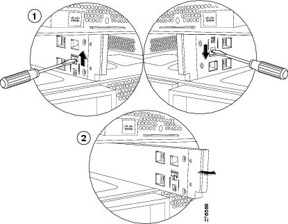
If necessary, remove the slot divider from the chassis.

  1. Simultaneously pull up on the left side catch and push down on the right side catch as shown in callout 1 of the following figure.

  2. Pull the slot divider out of the chassis as shown in callout 2 of the following figure. Keep the slot divider in case it is needed at another time.

    Figure 1. Removing a Slot Divider

    Tip


    To reinstall the slot divider, align it with the dimples in the slot top and bottom and slide it back in until it clicks into place.

Step 2

Grasp the front of the blade module and place your other hand under the blade to support it.
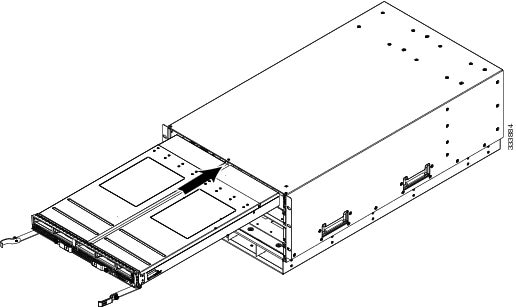
Figure 2. Positioning a UCS B260 M4 Blade Module in the Chassis

Step 3

Open the ejector levers in the front of the blade module.

Step 4

Gently slide the blade into the blade slot opening until you cannot push it any farther.

Step 5

Press the ejector levers so that they latch with the edge of the chassis and press the blade module all the way in.

Step 6

Tighten the captive screw on the front of the blade to no more than 3 in-lbs. Tightening with bare fingers will prevent stripped or damaged captive screws.

Step 7

Attach the UCS Scalability Terminator or UCS Scalability Connector to the blade module(s) as follows:

  1. Line up the four captive screws on the UCS Scalability Terminator with the holes on the front of the blade module(s).

  2. Push the UCS Scalability Terminator or UCS Scalability Connector into place.

  3. Tighten the captive screws on the front of the UCS Scalability Terminator or the UCS Scalability Connector.


Server Configuration

Cisco UCS blade servers can be configured and managed using the following UCS management software interfaces.

Cisco Intersight Managed Mode

Cisco UCS blade servers can be configured and managed using the Cisco Intersight management platform in Intersight Managed Mode (Cisco Intersight Managed Mode). For details, see the Cisco Intersight Managed Mode Configuration Guide, which is available at the following URL: https://www.cisco.com/c/en/us/td/docs/unified_computing/Intersight/b_Intersight_Managed_Mode_Configuration_Guide.html

Cisco UCS Manager

Cisco UCS blade servers can be configured and managed using Cisco UCS Manager. For details, see the Configuration Guide for the version of Cisco UCS Manager that you are using. The configuration guides are available at the following URL: http://www.cisco.com/en/US/products/ps10281/products_installation_and_configuration_guides_list.html

Powering Off a Blade Server Using the Power Button


Note


The front panel power button is disabled by default to ensure that servers are decommissioned through the UCS management software interface before shutdown. If you prefer to shut down the server locally with the button, you can enable front power-button control in the UCS management software interface.


Tip


You can also shut down servers remotely using the UCS management software interface. For details, see the configuration guide for the version the UCS management software interface that you are using. The configuration guides are available at the URLs documented in Server Configuration.


Procedure


Step 1

If you are local to the server, check the color of the Power Status LED for each server in the chassis that you want to power off.

  • Green indicates that the server is running and must be shut down before it can be safely powered off. Go to Step 2.

  • Amber indicates that the server is already in standby mode and can be safely powered off. Go to Step 3.

Step 2

If you previously enabled front power-button control through the UCS management software interface, press and release the Power button, then wait until the Power Status LED changes to amber.

The operating system performs a graceful shutdown, and the server goes to standby mode.

Caution


To avoid data loss or damage to your operating system, you should always invoke a graceful shutdown of the operating system.

Step 3

(Optional) Although not recommended, if you are shutting down all blade servers in a chassis, you can disconnect the power cords from the chassis to completely power off the servers.

Caution


To avoid data loss or damage to your operating system, you should always invoke a graceful shutdown of the operating system.


The blade servers will power down. You can now perform additional tasks with the blades as needed, for example, replacing a blade.

Removing a Blade Server from the Chassis

You must power off the blade server or decommission it using Cisco UCS Manager before physically removing the blade server from the chassis.

Procedure


Step 1

Turn off the blade server using either Cisco UCS Manager or the power button.

Step 2

If you are removing a UCS B460 M4 blade server, completely loosen the captive screws on the UCS Scalability Connector and remove the connector by pulling it away from the two UCS B260 blade modules. If you are removing a UCS B260 M4 blade server, you do not need to remove the UCS Scalability Terminator prior to removing the UCS B260 M4 blade server.

Step 3

Completely loosen the captive screws on the front of the blade.

Step 4

Remove the blade from the chassis by pulling the ejector levers on the blade until it unseats the blade server.

Step 5

Slide the blade part of the way out of the chassis, and place your other hand under the blade to support its weight.

Step 6

Once removed, place the blade on an antistatic mat or antistatic foam if you are not immediately reinstalling it.

Step 7

If the blade server slot is to remain empty, reinstall the slot divider and install two blade server blanking panels.


Basic Troubleshooting: Reseating a SAS/SATA Drive

Sometimes it is possible for a false positive UBAD error to occur on SAS/SATA HDDs installed in the server.

  • Only drives that are managed by the UCS MegaRAID controller are affected.

  • Drives can be affected regardless where they are installed in the server (front-loaded, rear-loaded, and so on).

  • Both SFF and LFF form factor drives can be affected.

  • Drives installed in all Cisco UCS C-Series servers with M3 processors and later can be affected.

  • Drives can be affected regardless of whether they are configured for hotplug or not.

  • The UBAD error is not always terminal, so the drive is not always defective or in need of repair or replacement. However, it is also possible that the error is terminal, and the drive will need replacement.

Before submitting the drive to the RMA process, it is a best practice to reseat the drive. If the false UBAD error exists, reseating the drive can clear it. If successful, reseating the drive reduces inconvenience, cost, and service interruption, and optimizes your server uptime.


Note


Reseat the drive only if a UBAD error occurs. Other errors are transient, and you should not attempt diagnostics and troubleshooting without the assistance of Cisco personnel. Contact Cisco TAC for assistance with other drive errors.


To reseat the drive, see Reseating a SAS/SATA Drive.

Reseating a SAS/SATA Drive

Sometimes, SAS/SATA drives can throw a false UBAD error, and reseating the drive can clear the error.

Use the following procedure to reseat the drive.


Caution


This procedure might require powering down the server. Powering down the server will cause a service interruption.


Before you begin

Before attempting this procedure, be aware of the following:

  • Before reseating the drive, it is a best practice to back up any data on it.

  • When reseating the drive, make sure to reuse the same drive bay.

    • Do not move the drive to a different slot.

    • Do not move the drive to a different server.

    • If you do not reuse the same slot, the Cisco management software (for example, Cisco IMM) might require a rescan/rediscovery of the server.

  • When reseating the drive, allow 20 seconds between removal and reinsertion.

Procedure


Step 1

Attempt a hot reseat of the affected drive(s). Choose the appropriate option.

Note


While the drive is removed, it is a best practice to perform a visual inspection. Check the drive bay to ensure that no dust or debris is present. Also, check the connector on the back of the drive and the connector on the inside of the server for any obstructions or damage.

Also, when reseating the drive, allow 20 seconds between removal and reinsertion.

Step 2

During boot up, watch the drive's LEDs to verify correct operation.

See Status LEDs and Buttons.

Step 3

If the error persists, cold reseat the drive, which requires a server power down. Choose the appropriate option:

  1. Use your server management software to gracefully power down the server.

    See the appropriate Cisco management software documentation.

  2. If server power down through software is not available, you can power down the server by pressing the power button.

    See Status LEDs and Buttons.

  3. Reseat the drive as documented in Step 1.

  4. When the drive is correctly reseated, restart the server, and check the drive LEDs for correct operation as documented in Step 2.

Step 4

If hot and cold reseating the drive (if necessary) does not clear the UBAD error, choose the appropriate option:

  1. Contact Cisco Systems for assistance with troubleshooting.

  2. Begin an RMA of the errored drive.