- Preface
- Overview
- Installing the Server OS
- Managing the Server
- Viewing Server Properties
- Viewing Sensors
- Managing Remote Presence
- Managing User Accounts
- Configuring Network-Related Settings
- Managing Network Adapters
- Managing Storage Adapters
- Configuring Communication Services
- Managing Certificates
- Configuring Platform Event Filters
- Cisco IMC Firmware Management
- Viewing Faults and Logs
- Server Utilities
- Troubleshooting
- BIOS Parameters by Server Model
- BIOS Token Name Comparison for Multiple Interfaces
- Index
- Overview of the Cisco UCS C-Series Network Adapters
- Viewing Network Adapter Properties
- Viewing VIC Adapter Properties
- Viewing Storage Adapter Properties
- Managing vHBAs
- Managing vNICs
- Backing Up and Restoring the Adapter Configuration
- Managing Adapter Firmware
- Resetting the Adapter
Managing Network
Adapters
This chapter includes the following sections:
- Overview of the Cisco UCS C-Series Network Adapters
- Viewing Network Adapter Properties
- Viewing VIC Adapter Properties
- Viewing Storage Adapter Properties
- Managing vHBAs
- Managing vNICs
- Backing Up and Restoring the Adapter Configuration
- Managing Adapter Firmware
- Resetting the Adapter
Overview of the Cisco UCS C-Series Network Adapters
 Note | The procedures in this chapter are available only when a Cisco UCS C-Series network adapter is installed in the chassis. |
A Cisco UCS C-Series network adapter can be installed to provide options for I/O consolidation and virtualization support. The following adapters are available:
-
Cisco UCS P81E Virtual Interface Card
-
Cisco UCS VIC 1225 Virtual Interface Card
-
Cisco UCS VIC 1385 Virtual Interface Card
-
Cisco UCS VIC 1227T Virtual Interface Card
-
Cisco UCS VIC 1387 Virtual Interface Card
The interactive UCS Hardware and Software Interoperability Utility lets you view the supported components and configurations for a selected server model and software release. The utility is available at the following URL: http://www.cisco.com/web/techdoc/ucs/interoperability/matrix/matrix.html
Cisco UCS P81E Virtual Interface Card
The Cisco UCS P81E Virtual Interface Card is optimized for virtualized environments, for organizations that seek increased mobility in their physical environments, and for data centers that want reduced costs through NIC, HBA, cabling, and switch reduction and reduced management overhead. This Fibre Channel over Ethernet (FCoE) PCIe card offers the following benefits:
-
Allows up to 16 virtual Fibre Channel and 16 virtual Ethernet adapters to be provisioned in virtualized or nonvirtualized environments using just-in-time provisioning, providing tremendous system flexibility and allowing consolidation of multiple physical adapters.
-
Delivers uncompromising virtualization support, including hardware-based implementation of Cisco VN-Link technology and pass-through switching.
-
Improves system security and manageability by providing visibility and portability of network polices and security all the way to the virtual machine.
The virtual interface card makes Cisco VN-Link connections to the parent fabric interconnects, which allows virtual links to connect virtual NICs in virtual machines to virtual interfaces in the interconnect. In a Cisco Unified Computing System environment, virtual links then can be managed, network profiles applied, and interfaces dynamically reprovisioned as virtual machines move between servers in the system.
Cisco UCS VIC 1225 Virtual Interface Card
The Cisco UCS VIC 1225 Virtual Interface Card is a high-performance, converged network adapter that provides acceleration for the various new operational modes introduced by server virtualization. It brings superior flexibility, performance, and bandwidth to the new generation of Cisco UCS C-Series Rack-Mount Servers.
The Cisco UCS VIC 1225 implements the Cisco Virtual Machine Fabric Extender (VM-FEX), which unifies virtual and physical networking into a single infrastructure. It provides virtual-machine visibility from the physical network and a consistent network operations model for physical and virtual servers. In virtualized environments, this highly configurable and self-virtualized adapter provides integrated, modular LAN interfaces on Cisco UCS C-Series Rack-Mount Servers. Additional features and capabilities include:
-
Supports up to 256 PCIe virtual devices, either virtual network interface cards (vNICs) or virtual host bus adapters (vHBAs), with high I/O operations per second (IOPS), support for lossless Ethernet, and 20 Gbps to servers.
-
PCIe Gen2 x16 helps assure optimal bandwidth to the host for network-intensive applications with a redundant path to the fabric interconnect.
-
Half-height design reserves full-height slots in servers for Cisco certified third-party adapters.
-
Centrally managed by Cisco UCS Manager with support for Microsoft Windows, Red Hat Enterprise Linux, SUSE Linux, VMware vSphere, and Citrix XenServer.
Cisco UCS VIC 1385 Virtual Interface Card
The Cisco UCS VIC 1385 Virtual Interface Cardis a dual-port Enhanced Quad Small Form-Factor Pluggable (QSFP) 40 Gigabit Ethernet and Fibre Channel over Ethernet (FCoE)-capable half-height PCI Express (PCIe) card designed exclusively for Cisco UCS C-Series Rack Servers. It incorporates Cisco’s next-generation converged network adapter (CNA) technology, with a comprehensive feature set, providing investment protection for future feature software releases. The card enables a policy-based, stateless, agile server infrastructure that can present over 256 PCIe standards-compliant interfaces to the host that can be dynamically configured as either network interface cards (NICs) or host bus adapters (HBAs). In addition, the Cisco UCS VIC 1385 card supports Cisco Data Center Virtual Machine Fabric Extender (VM-FEX) technology, which extends the Cisco UCS fabric interconnect ports to virtual machines, simplifying server virtualization deployment.
The personality of the card is determined dynamically at boot time using the service profile associated with the server. The number, type (NIC or HBA), identity (MAC address and World Wide Name [WWN]), failover policy, bandwidth, and quality-of-service (QoS) policies of the PCIe interfaces are all determined using the service profile. The capability to define, create, and use interfaces on demand provides a stateless and agile server infrastructure. Additional features and capabilities include:
- Each PCIe interface created on the VIC is associated with an interface on the Cisco UCS fabric interconnect, providing complete network separation for each virtual cable between a PCIe device on the VIC and the interface on the fabric interconnect
-
The Cisco UCS VIC 1385 Virtual Interface Card provides high network performance and low latency for the most demanding applications such as SMB-Direct, VMQ, DPDK, and Cisco NetFlow
Cisco UCS VIC 1227T Virtual Interface Card
The Cisco UCS VIC 1227T Virtual Interface Card is a dual-port 10GBASE-T (RJ-45) 10-Gbps Ethernet and Fibre Channel over Ethernet (FCoE)–capable PCI Express (PCIe) modular LAN-on-motherboard (mLOM) adapter designed exclusively for Cisco UCS C-Series Rack Servers. New to Cisco rack servers, the mLOM slot can be used to install a Cisco VIC without consuming a PCIe slot, which provides greater I/O expandability. It incorporates next-generation converged network adapter (CNA) technology from Cisco, providing Fibre Channel connectivity over low-cost twisted pair cabling with a bit error rate (BER) of 10 to 15 up to 30 meters and investment protection for future feature releases. The mLOM card enables a policy-based, stateless, agile server infrastructure that can present up to 256 PCIe standards-compliant interfaces to the host that can be dynamically configured as either network interface cards (NICs) or host bus adapters (HBAs). In addition, the Cisco UCS VIC 1227T Virtual Interface Card supports Cisco Data Center Virtual Machine Fabric Extender (VM-FEX) technology, which extends the Cisco UCS fabric interconnect ports to virtual machines, simplifying server virtualization deployment. Additional features and capabilities include:
- Stateless and agile design - The personality of the card is determined dynamically at boot time using the service profile associated with the server. The number, type (NIC or HBA), identity (MAC address and World Wide Name [WWN]), failover policy, bandwidth, and quality-of-service (QoS) policies of the PCIe interfaces are all determined using the service profile. The capability to define, create, and use interfaces on demand provides a stateless and agile server infrastructure.
-
Each PCIe interface created on the VIC is associated with an interface on the Cisco UCS fabric interconnect, providing complete network separation for each virtual cable between a PCIe device on the VIC and the interface on the fabric interconnect.
-
Cisco SingleConnect technology provides an exceptionally easy, intelligent, and efficient way to connect and manage computing in the data center. Cisco SingleConnect technology dramatically simplifies the way that data centers connect to rack and blade servers, physical servers, virtual machines, LANs, SANs, and management networks.
Cisco UCS VIC 1387 Virtual Interface Card
The Cisco UCS VIC 1387 Virtual Interface Card is a dual-port Enhanced Quad Small Form-Factor Pluggable (QSFP) 40 Gigabit Ethernet and Fibre Channel over Ethernet (FCoE)-capable half-height PCI Express (PCIe) card designed exclusively for Cisco UCS C-Series Rack Servers. It incorporates Cisco’s next-generation converged network adapter (CNA) technology, with a comprehensive feature set, providing investment protection for future feature software releases. The card enables a policy-based, stateless, agile server infrastructure that can present over 256 PCIe standards-compliant interfaces to the host that can be dynamically configured as either network interface cards (NICs) or host bus adapters (HBAs). In addition, the Cisco UCS VIC 1387 card supports Cisco Data Center Virtual Machine Fabric Extender (VM-FEX) technology, which extends the Cisco UCS fabric interconnect ports to virtual machines, simplifying server virtualization deployment.
The personality of the card is determined dynamically at boot time using the service profile associated with the server. The number, type (NIC or HBA), identity (MAC address and World Wide Name [WWN]), failover policy, bandwidth, and quality-of-service (QoS) policies of the PCIe interfaces are all determined using the service profile. The capability to define, create, and use interfaces on demand provides a stateless and agile server infrastructure. Additional features and capabilities include:
- Each PCIe interface created on the VIC is associated with an interface on the Cisco UCS fabric interconnect, providing complete network separation for each virtual cable between a PCIe device on the VIC and the interface on the fabric interconnect
-
The Cisco UCS VIC 1387 Virtual Interface Card provides high network performance and low latency for the most demanding applications such as SMB-Direct, VMQ, DPDK, and Cisco NetFlow
Viewing Network Adapter Properties
Viewing VIC Adapter Properties
| Step 1 | In the Navigation pane, click the Server tab. | ||||||||||||||||||||||||||||||||||||||||||||
| Step 2 | On the Server tab, click Inventory. | ||||||||||||||||||||||||||||||||||||||||||||
| Step 3 | In the Inventory pane, click the Cisco VIC Adapters tab. | ||||||||||||||||||||||||||||||||||||||||||||
| Step 4 | In the
Adapter
Cards area, click an adapter in the table to display its properties.
The resources of the selected adapter appear in the tabbed menu below the Adapter Cards area. | ||||||||||||||||||||||||||||||||||||||||||||
| Step 5 | In the
Adapter
Cards area, review the following information for the installed
adapters:
| ||||||||||||||||||||||||||||||||||||||||||||
| Step 6 | In the tabbed menu below the Adapter Cards area, click the General tab. | ||||||||||||||||||||||||||||||||||||||||||||
| Step 7 | In the
Adapter
Card Properties area, review the following information for the
adapter:
| ||||||||||||||||||||||||||||||||||||||||||||
| Step 8 | In the
External
Ethernet Interfaces area, review the following information for the
adapter:
| ||||||||||||||||||||||||||||||||||||||||||||
| Step 9 | In the
Firmware area, review the following information for
the adapter:
|
What to Do Next
To view the properties of virtual NICs and virtual HBAs, see the following sections:
Viewing Storage Adapter Properties
| Step 1 | In the Navigation pane, click the Server tab. | ||||||||||||||||||||||
| Step 2 | On the Server tab, click Inventory. | ||||||||||||||||||||||
| Step 3 |
In the Inventory pane, click Storage Adapters tab and review the following information:
|
Managing vHBAs
Guidelines for Managing vHBAs
When managing vHBAs, consider the following guidelines and restrictions:
-
The Cisco UCS P81E Virtual Interface Card and Cisco UCS VIC 1225 Virtual Interface Card provide two vHBAs (fc0 and fc1). You can create up to 16 additional vHBAs on these adapter cards.
Note
If Network Interface Virtualization (NIV) mode is enabled for the adapter, you must assign a channel number to a vHBA when you create it.
-
When using the Cisco UCS P81E Virtual Interface Card or Cisco UCS VIC 1225 Virtual Interface Card in an FCoE application, you must associate the vHBA with the FCoE VLAN. Follow the instructions in the Modifying vHBA Properties section to assign the VLAN.
-
After making configuration changes, you must reboot the host for settings to take effect.
Viewing vHBA Properties
| Step 1 | In the Navigation pane, click the Server tab. | ||||||||||||||||||||||||||||||||||||||||||||
| Step 2 | On the Server tab, click Inventory. | ||||||||||||||||||||||||||||||||||||||||||||
| Step 3 | In the Inventory pane, click the Cisco VIC Adapters tab. | ||||||||||||||||||||||||||||||||||||||||||||
| Step 4 | In the
Adapter Cards area, select the adapter card.
If the server is powered on, the resources of the selected adapter card appear in the tabbed menu below the Adapter Cards area. | ||||||||||||||||||||||||||||||||||||||||||||
| Step 5 | In the tabbed menu below the Adapter Cards area, click the vHBAs tab. | ||||||||||||||||||||||||||||||||||||||||||||
| Step 6 | In the Host Fibre Channel Interfaces area, select a vHBA from the table. | ||||||||||||||||||||||||||||||||||||||||||||
| Step 7 | Click Properties to open the vHBA Properties dialog box. | ||||||||||||||||||||||||||||||||||||||||||||
| Step 8 |
In the General area, review the information in the following fields:
| ||||||||||||||||||||||||||||||||||||||||||||
| Step 9 |
In the Error Recovery area, review the information in the following fields:
| ||||||||||||||||||||||||||||||||||||||||||||
| Step 10 |
In the Fibre Channel Interrupt area, review the information in the following fields:
| ||||||||||||||||||||||||||||||||||||||||||||
| Step 11 |
In the Fibre Channel Port area, review the information in the following fields:
| ||||||||||||||||||||||||||||||||||||||||||||
| Step 12 |
In the Fibre Channel Port FLOGI area, review the information in the following fields:
| ||||||||||||||||||||||||||||||||||||||||||||
| Step 13 |
In the Fibre Channel Port PLOGI area, review the information in the following fields:
| ||||||||||||||||||||||||||||||||||||||||||||
| Step 14 |
In the SCSI I/O area, review the information in the following fields:
| ||||||||||||||||||||||||||||||||||||||||||||
| Step 15 |
In the Receive/Transmit Queues area, review the information in the following fields:
|
Modifying vHBA Properties
| Step 1 | In the Navigation pane, click the Server tab. | ||||||||||||||||||||||||||||||||||||||||||||
| Step 2 | On the Server tab, click Inventory. | ||||||||||||||||||||||||||||||||||||||||||||
| Step 3 | In the Inventory pane, click the Cisco VIC Adapters tab. | ||||||||||||||||||||||||||||||||||||||||||||
| Step 4 | In the
Adapter Cards area, select the adapter card.
If the server is powered on, the resources of the selected adapter card appear in the tabbed menu below the Adapter Cards area. | ||||||||||||||||||||||||||||||||||||||||||||
| Step 5 | In the tabbed menu below the Adapter Cards area, click the vHBAs tab. | ||||||||||||||||||||||||||||||||||||||||||||
| Step 6 | In the Host Fibre Channel Interfaces area, select a vHBA from the table. | ||||||||||||||||||||||||||||||||||||||||||||
| Step 7 | Click Properties to open the vHBA Properties dialog box. | ||||||||||||||||||||||||||||||||||||||||||||
| Step 8 | In the General area, update the following fields:
| ||||||||||||||||||||||||||||||||||||||||||||
| Step 9 | In the Error Recovery area, update the following fields:
| ||||||||||||||||||||||||||||||||||||||||||||
| Step 10 | In the Fibre Channel Interrupt area, update the following fields:
| ||||||||||||||||||||||||||||||||||||||||||||
| Step 11 | In the Fibre Channel Port area, update the following fields:
| ||||||||||||||||||||||||||||||||||||||||||||
| Step 12 | In the Fibre Channel Port FLOGI area, update the following fields:
| ||||||||||||||||||||||||||||||||||||||||||||
| Step 13 | In the Fibre Channel Port PLOGI area, update the following fields:
| ||||||||||||||||||||||||||||||||||||||||||||
| Step 14 | In the SCSI I/O area, update the following fields:
| ||||||||||||||||||||||||||||||||||||||||||||
| Step 15 | In the Receive/Transmit Queues area, update the following fields:
| ||||||||||||||||||||||||||||||||||||||||||||
| Step 16 | Click Save Changes. |
Creating a vHBA
The adapter provides two permanent vHBAs. If NIV mode is enabled, you can create up to 16 additional vHBAs.
| Step 1 | In the Navigation pane, click the Server tab. |
| Step 2 | On the Server tab, click Inventory. |
| Step 3 | In the Inventory pane, click the Cisco VIC Adapters tab. |
| Step 4 | In the
Adapter Cards area, select the adapter card.
If the server is powered on, the resources of the selected adapter card appear in the tabbed menu below the Adapter Cards area. |
| Step 5 | In the tabbed menu below the Adapter Cards area, click the vHBAs tab. |
| Step 6 |
In the
Host Fibre Channel Interfaces area, choose one of these actions:
The Add vHBA dialog box appears. |
| Step 7 | In the Add vHBA dialog box, enter a name for the vHBA in the Name entry box. |
| Step 8 | Click Add vHBA. |
What to Do Next
Reboot the server to create the vHBA.
If configuration changes are required, configure the new vHBA as described in Modifying vHBA Properties.
Deleting a vHBA
| Step 1 | In the Navigation pane, click the Server tab. | ||
| Step 2 | On the Server tab, click Inventory. | ||
| Step 3 | In the Inventory pane, click the Cisco VIC Adapters tab. | ||
| Step 4 | In the
Adapter Cards area, select the adapter card.
If the server is powered on, the resources of the selected adapter card appear in the tabbed menu below the Adapter Cards area. | ||
| Step 5 | In the tabbed menu below the Adapter Cards area, click the vHBAs tab. | ||
| Step 6 | In the Host Fibre Channel Interfaces area, select a vHBA from the table.
| ||
| Step 7 | Click Delete and click OK to confirm. |
vHBA Boot Table
In the vHBA boot table, you can specify up to four LUNs from which the server can boot.
Creating a Boot Table Entry
| Step 1 | In the Navigation pane, click the Server tab. | ||||||||||||
| Step 2 | On the Server tab, click Inventory. | ||||||||||||
| Step 3 | In the Inventory pane, click the Cisco VIC Adapters tab. | ||||||||||||
| Step 4 | In the
Adapter Cards area, select the adapter card.
If the server is powered on, the resources of the selected adapter card appear in the tabbed menu below the Adapter Cards area. | ||||||||||||
| Step 5 | In the tabbed menu below the Adapter Cards area, click the vHBAs tab. | ||||||||||||
| Step 6 | In the Host Fibre Channel Interfaces area, select a vHBA from the table. | ||||||||||||
| Step 7 | Click Boot Table to open the Boot Table dialog box for the selected vHBA. | ||||||||||||
| Step 8 | In the Boot Table dialog box, click Add to open the Add Boot Entry dialog box. | ||||||||||||
| Step 9 | In the Add Boot Entry dialog box, update the following fields:
| ||||||||||||
| Step 10 | Click Add Boot Entry. |
Deleting a Boot Table Entry
| Step 1 | In the Navigation pane, click the Server tab. |
| Step 2 | On the Server tab, click Inventory. |
| Step 3 | In the Inventory pane, click the Cisco VIC Adapters tab. |
| Step 4 | In the
Adapter Cards area, select the adapter card.
If the server is powered on, the resources of the selected adapter card appear in the tabbed menu below the Adapter Cards area. |
| Step 5 | In the tabbed menu below the Adapter Cards area, click the vHBAs tab. |
| Step 6 | In the Host Fibre Channel Interfaces area, select a vHBA from the table. |
| Step 7 | Click Boot Table to open the Boot Table dialog box for the selected vHBA. |
| Step 8 | In the Boot Table dialog box, click the entry to be deleted. |
| Step 9 | Click Delete and click OK to confirm. |
vHBA Persistent Binding
Persistent binding ensures that the system-assigned mapping of Fibre Channel targets is maintained after a reboot.
Viewing Persistent Bindings
| Step 1 | In the Navigation pane, click the Server tab. | ||||||||||||||||
| Step 2 | On the Server tab, click Inventory. | ||||||||||||||||
| Step 3 | In the Inventory pane, click the Cisco VIC Adapters tab. | ||||||||||||||||
| Step 4 | In the
Adapter Cards area, select the adapter card.
If the server is powered on, the resources of the selected adapter card appear in the tabbed menu below the Adapter Cards area. | ||||||||||||||||
| Step 5 | In the tabbed menu below the Adapter Cards area, click the vHBAs tab. | ||||||||||||||||
| Step 6 | In the Host Fibre Channel Interfaces area, select a vHBA from the table. | ||||||||||||||||
| Step 7 | Click Persistent Bindings to open the Persistent Bindings dialog box for the selected vHBA. | ||||||||||||||||
| Step 8 | In the Persistent Bindings dialog box for the selected vHBA, review the following information:
| ||||||||||||||||
| Step 9 | Click Close. |
Rebuilding Persistent Bindings
| Step 1 | In the Navigation pane, click the Server tab. |
| Step 2 | On the Server tab, click Inventory. |
| Step 3 | In the Inventory pane, click the Cisco VIC Adapters tab. |
| Step 4 | In the
Adapter Cards area, select the adapter card.
If the server is powered on, the resources of the selected adapter card appear in the tabbed menu below the Adapter Cards area. |
| Step 5 | In the tabbed menu below the Adapter Cards area, click the vHBAs tab. |
| Step 6 | In the Host Fibre Channel Interfaces area, select a vHBA from the table. |
| Step 7 | Click Persistent Bindings to open the Persistent Bindings dialog box for the selected vHBA. |
| Step 8 | In the Persistent Bindings dialog box for the selected vHBA, click Rebuild Persistent Bindings. |
| Step 9 | Click Close. |
Managing vNICs
Guidelines for Managing vNICs
When managing vNICs, consider the following guidelines and restrictions:
-
The Cisco UCS P81E Virtual Interface Card and Cisco UCS VIC 1225 Virtual Interface Card provide two default vNICs (eth0 and eth1). You can create up to 16 additional vNICs on these adapter cards.
Note
If Network Interface Virtualization (NIV) mode is enabled for the adapter, you must assign a channel number to a vNIC when you create it.
-
After making configuration changes, you must reboot the host for settings to take effect.
Cisco C-series servers use Remote Direct Memory Access (RDMA) over Converged Ethernet (RoCE) for packet transfers. RoCE defines the mechanism of performing RDMA over ethernet, based on the similar mechanism of RDMA over Infiniband. However, RoCE, with its performance oriented characteristics, delivers a superior performance compared to traditional network socket implementation because of the lower latency, lower CPU utilization and higher utilization of network bandwidth. RoCE meets the requirement of moving large amount of data across networks very efficiently.
Viewing vNIC Properties
| Step 1 | In the Navigation pane, click the Networking menu. | ||||||||||||||||||||||||||||||||||||||||||||||||||||||||||||||||||
| Step 2 | In the Adapter Card pane, click the vNICs tab. | ||||||||||||||||||||||||||||||||||||||||||||||||||||||||||||||||||
| Step 3 | In the vNICs pane, click eth0 or eth1. | ||||||||||||||||||||||||||||||||||||||||||||||||||||||||||||||||||
| Step 4 | In the
Ethernet Interfaces pane's
vNIC
Properties area, review the information in the following fields:
| ||||||||||||||||||||||||||||||||||||||||||||||||||||||||||||||||||
| Step 5 | In the
Ethernet
Interrupt area, review the information in the following fields:
| ||||||||||||||||||||||||||||||||||||||||||||||||||||||||||||||||||
| Step 6 | In the
Ethernet
Receive Queue area, review the information in the following fields:
| ||||||||||||||||||||||||||||||||||||||||||||||||||||||||||||||||||
| Step 7 | In the
Ethernet
Transmit Queue area, review the information in the following
fields:
| ||||||||||||||||||||||||||||||||||||||||||||||||||||||||||||||||||
| Step 8 | In the
Completion Queue area, review the information in the
following fields:
| ||||||||||||||||||||||||||||||||||||||||||||||||||||||||||||||||||
| Step 9 | In the
TCP
Offload area, review the information in the following fields:
| ||||||||||||||||||||||||||||||||||||||||||||||||||||||||||||||||||
| Step 10 | In the
Receive Side Scaling area, review the information in
the following fields:
|
Modifying vNIC Properties
| Step 1 | In the Navigation pane, click the Server tab. | ||||||||||||||||||||||||||||||||||||||||||||||||||||||||||||||||||
| Step 2 | On the Server tab, click Inventory. | ||||||||||||||||||||||||||||||||||||||||||||||||||||||||||||||||||
| Step 3 | In the Inventory pane, click the Cisco VIC Adapters tab. | ||||||||||||||||||||||||||||||||||||||||||||||||||||||||||||||||||
| Step 4 | In the
Adapter Cards area, select the adapter card.
If the server is powered on, the resources of the selected adapter card appear in the tabbed menu below the Adapter Cards area. | ||||||||||||||||||||||||||||||||||||||||||||||||||||||||||||||||||
| Step 5 | In the tabbed menu below the Adapter Cards area, click the vNICs tab. | ||||||||||||||||||||||||||||||||||||||||||||||||||||||||||||||||||
| Step 6 | In the Host Ethernet Interfaces area, select a vNIC from the table. | ||||||||||||||||||||||||||||||||||||||||||||||||||||||||||||||||||
| Step 7 | Click Properties to open the vNIC Properties dialog box. | ||||||||||||||||||||||||||||||||||||||||||||||||||||||||||||||||||
| Step 8 | In the
General area, update the following fields:
| ||||||||||||||||||||||||||||||||||||||||||||||||||||||||||||||||||
| Step 9 | In the
Ethernet
Interrupt area, update the following fields:
| ||||||||||||||||||||||||||||||||||||||||||||||||||||||||||||||||||
| Step 10 | In the
Ethernet
Receive Queue area, update the following fields:
| ||||||||||||||||||||||||||||||||||||||||||||||||||||||||||||||||||
| Step 11 | In the
Ethernet
Transmit Queue area, update the following fields:
| ||||||||||||||||||||||||||||||||||||||||||||||||||||||||||||||||||
| Step 12 | In the
Completion Queue area, update the following fields:
| ||||||||||||||||||||||||||||||||||||||||||||||||||||||||||||||||||
| Step 13 | In the
RoCE
Properties area, update the following fields:
| ||||||||||||||||||||||||||||||||||||||||||||||||||||||||||||||||||
| Step 14 | In the
TCP
Offload area, update the following fields:
| ||||||||||||||||||||||||||||||||||||||||||||||||||||||||||||||||||
| Step 15 | In the
Receive Side Scaling area, update the following
fields:
| ||||||||||||||||||||||||||||||||||||||||||||||||||||||||||||||||||
| Step 16 | Click Save Changes. |
Creating a vNIC
The adapter provides two permanent vNICs. You can create up to 16 additional vNICs.
| Step 1 | In the Navigation pane, click the Server tab. | ||
| Step 2 | On the Server tab, click Inventory. | ||
| Step 3 | In the Inventory pane, click the Cisco VIC Adapters tab. | ||
| Step 4 | In the
Adapter Cards area, select the adapter card.
If the server is powered on, the resources of the selected adapter card appear in the tabbed menu below the Adapter Cards area. | ||
| Step 5 | In the tabbed menu below the Adapter Cards area, click the vNICs tab. | ||
| Step 6 |
In the
Host Ethernet Interfaces area, choose one of these actions:
The Add vNIC dialog box appears. | ||
| Step 7 | In the Add vNIC dialog box, enter a name for the vNIC in the Name entry box. | ||
| Step 8 | (Optional)In the Add vNIC dialog box, enter a channel number for the vNIC in the Channel Number entry box.
| ||
| Step 9 | Click Add vNIC. |
What to Do Next
If configuration changes are required, configure the new vNIC as described in Modifying vNIC Properties.
Deleting a vNIC
| Step 1 | In the Navigation pane, click the Server tab. | ||
| Step 2 | On the Server tab, click Inventory. | ||
| Step 3 | In the Inventory pane, click the Cisco VIC Adapters tab. | ||
| Step 4 | In the
Adapter Cards area, select the adapter card.
If the server is powered on, the resources of the selected adapter card appear in the tabbed menu below the Adapter Cards area. | ||
| Step 5 | In the tabbed menu below the Adapter Cards area, click the vNICs tab. | ||
| Step 6 | In the Host Ethernet Interfaces area, select a vNIC from the table.
| ||
| Step 7 | Click Delete and click OK to confirm. |
Managing Cisco usNIC
Overview of Cisco usNIC
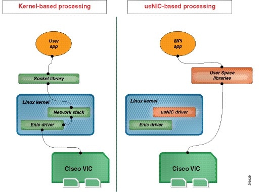
The Cisco user-space NIC (Cisco usNIC) feature improves the performance of software applications that run on the Cisco UCS servers in your data center by bypassing the kernel when sending and receiving networking packets. The applications interact directly with a Cisco UCS VIC second generation or later generation adapter, such as the , which improves the networking performance of your high-performance computing cluster. To benefit from Cisco usNIC, your applications must use the Message Passing Interface (MPI) instead of sockets or other communication APIs.
Cisco usNIC offers the following benefits for your MPI applications:
-
Provides a low-latency and high-throughput communication transport.
-
Employs the standard and application-independent Ethernet protocol.
-
Takes advantage of lowlatency forwarding, Unified Fabric, and integrated management support in the following Cisco data center platforms:
Standard Ethernet applications use user-space socket libraries, which invoke the networking stack in the Linux kernel. The networking stack then uses the Cisco eNIC driver to communicate with the Cisco VIC hardware. The following figure shows the contrast between a regular software application and an MPI application that uses Cisco usNIC.
Configuring Cisco usNIC Using the Cisco IMC GUI
Note | Even though several properties are listed for Cisco usNIC in the usNIC properties dialog box, you must configure only the following properties because the other properties are not currently being used. |
You must log in to the Cisco IMC GUI with administrator privileges to perform this task. Click Play on this video to watch how to configure Cisco usNIC in CIMC.
| Step 1 | Log into the
Cisco IMC
GUI.
For more information about how to log into Cisco IMC, see Cisco UCS C-Series Servers Integrated Management Controller GUI Configuration Guide. | ||||||||
| Step 2 | In the Navigation pane, click the Server tab. | ||||||||
| Step 3 | On the Server tab, click Inventory. | ||||||||
| Step 4 | In the Inventory pane, click the Cisco VIC Adapters tab. | ||||||||
| Step 5 | In the
Adapter Cards area, select the adapter card.
If the server is powered on, the resources of the selected adapter card appear in the tabbed menu below the Adapter Cards area. | ||||||||
| Step 6 | In the tabbed menu below the Adapter Cards area, click the vNICs tab. | ||||||||
| Step 7 | In the
Host
Ethernet Interfaces area, select a vNIC from the table.
| ||||||||
| Step 8 | Click usNIC to open the usNIC Properties dialog box. | ||||||||
| Step 9 | In the
usNICs property, specify the number of Cisco usNICs
that you want to create.
Each MPI process that is running on the server requires a dedicated usNIC. You might need to create up to 64 usNICs to sustain 64 MPI processes running simultaneously. We recommend that you create at least as many usNICs, per usNIC-enabled vNIC, as the number of physical cores on your server. For example, if you have 8 physical cores on your server, create 8 usNICs. | ||||||||
| Step 10 | In the
Properties area, update the following fields:
| ||||||||
| Step 11 | Click Apply. | ||||||||
| Step 12 | In the Navigation pane, click the Server tab. | ||||||||
| Step 13 | On the Server tab, click BIOS. | ||||||||
| Step 14 | In the Actions area, click Configure BIOS. | ||||||||
| Step 15 | In the Configure BIOS Parameters dialog box, click the Advanced tab. | ||||||||
| Step 16 | In the
Processor Configuration area, set the following
properties to
Enabled:
| ||||||||
| Step 17 | Click
Save
Changes.
The changes take effect upon the next server reboot. |
Viewing usNIC Properties
| Step 1 | In the Navigation pane, click the Server tab. | ||||||||||||||||||||||||||||||||||||||||
| Step 2 | On the Server tab, click Inventory. | ||||||||||||||||||||||||||||||||||||||||
| Step 3 | In the Inventory pane, click the Cisco VIC Adapters tab. | ||||||||||||||||||||||||||||||||||||||||
| Step 4 | In the
Adapter Cards area, select the adapter card.
If the server is powered on, the resources of the selected adapter card appear in the tabbed menu below the Adapter Cards area. | ||||||||||||||||||||||||||||||||||||||||
| Step 5 | In the tabbed menu below the Adapter Cards area, click the vNICs tab. | ||||||||||||||||||||||||||||||||||||||||
| Step 6 | In the Host Ethernet Interface area, select the usNIC that is assigned to vNIC, to open the usNIC properties dialog box. | ||||||||||||||||||||||||||||||||||||||||
| Step 7 | In the usNIC area, review or update the information in the following fields:
| ||||||||||||||||||||||||||||||||||||||||
| Step 8 | In the Properties area, review or update the information in the following fields:
|
Configuring iSCSI Boot Capability
Configuring iSCSI Boot Capability for vNICs
When the rack-servers are configured in a standalone mode, and when the VIC adapters are directly attached to the Nexus 5000 family of switches, you can configure these VIC adapters to boot the servers remotely from iSCSI storage targets. You can configure Ethernet vNICs to enable a rack server to load the host OS image from remote iSCSI target devices.
To configure the iSCSI boot capability on a vNIC:
-
You must log in with admin privileges to perform this task.
-
To configure a vNIC to boot a server remotely from an iSCSI storage target, you must enable the PXE boot option on the vNIC.
Note | You can configure a maximum of 2 iSCSI vNICs for each host. |
Configuring iSCSI Boot Capability on a vNIC
You can configure a maximum of 2 iSCSI vNICs for each host.
| Step 1 | In the Navigation pane, click the Server tab. | ||||||||||||||||||||||||
| Step 2 | On the Server tab, click Inventory. | ||||||||||||||||||||||||
| Step 3 | In the Inventory pane, click the Cisco VIC Adapters tab. | ||||||||||||||||||||||||
| Step 4 | In the
Adapter Cards area, select the adapter card.
If the server is powered on, the resources of the selected adapter card appear in the tabbed menu below the Adapter Cards area. | ||||||||||||||||||||||||
| Step 5 | In the tabbed menu below the Adapter Cards area, click the vNICs tab. | ||||||||||||||||||||||||
| Step 6 | In the Host Ethernet Interfaces area, select a vNIC from the table, and click iSCSI Boot. | ||||||||||||||||||||||||
| Step 7 | In the General Area, update the following fields:
| ||||||||||||||||||||||||
| Step 8 | In the Initiator Area, update the following fields:
| ||||||||||||||||||||||||
| Step 9 | In the Primary Target Area, update the following fields:
| ||||||||||||||||||||||||
| Step 10 | In the Secondary Target Area, update the following fields:
| ||||||||||||||||||||||||
| Step 11 | Click Configure ISCSI. |
Removing iSCSI Boot Configuration from a vNIC
You must log in with admin privileges to perform this task.
| Step 1 | In the Navigation pane, click the Server tab. |
| Step 2 | On the Server tab, click Inventory. |
| Step 3 | In the Inventory pane, click the Cisco VIC Adapters tab. |
| Step 4 | In the
Adapter Cards area, select the adapter card.
If the server is powered on, the resources of the selected adapter card appear in the tabbed menu below the Adapter Cards area. |
| Step 5 | In the tabbed menu below the Adapter Cards area, click the vNICs tab. |
| Step 6 | In the Host Ethernet Interfaces area, select a vNIC from the table, and click iSCSI Boot. |
| Step 7 | In the dialog box that appears, click Unconfigure ISCSI. |
Configuring Virtual Machine Queues on a vNIC
You must log in to the Cisco IMC GUI with administrator privileges to perform this task.
| Step 1 | In the Navigation pane, click the Networking menu. |
| Step 2 | In the Adapter Card pane, click the vNICs tab. |
| Step 3 | In the Ethernet Interfaces pane's vNIC Properties area, check the Enable VMQ checkbox. |
| Step 4 | In the Ethernet Transmit Queue area, enter an integer in the Transmit Queue Count field. This number should be greater than 1. |
| Step 5 | In the Ethernet Receive Queue area, enter an integer in the Receive Queue Count field. This number should be equal to the number of transmit queues. |
| Step 6 | In the Ethernet Interrupt area, enter an integer in the Interrupt Count field. This should be equal to the number of logical processors, or completion queues. |
What to Do Next
Backing Up and Restoring the Adapter Configuration
Exporting the Adapter Configuration
The adapter configuration can be exported as an XML file to a remote server which can be one of the following:
Obtain the remote server IP address.
| Step 1 | In the Navigation pane, click the Server tab. | ||||||||||||||
| Step 2 | On the Server tab, click Inventory. | ||||||||||||||
| Step 3 | In the Inventory pane, click the Cisco VIC Adapters tab. | ||||||||||||||
| Step 4 | In the
Adapter Cards area, select the adapter card.
If the server is powered on, the resources of the selected adapter card appear in the tabbed menu below the Adapter Cards area. | ||||||||||||||
| Step 5 | In the tabbed menu below the Adapter Cards area, click the General tab. | ||||||||||||||
| Step 6 |
In the Actions area of the
General tab, click Export Configuration.
The Export Adapter Configuration dialog box opens. | ||||||||||||||
| Step 7 |
In the Export Adapter Configuration dialog box, update the following fields:
| ||||||||||||||
| Step 8 | Click Export Configuration. |
Importing the Adapter Configuration
| Step 1 | In the Navigation pane, click the Server tab. | ||||||||||||||
| Step 2 | On the Server tab, click Inventory. | ||||||||||||||
| Step 3 | In the Inventory pane, click the Cisco VIC Adapters tab. | ||||||||||||||
| Step 4 | In the
Adapter Cards area, select the adapter card.
If the server is powered on, the resources of the selected adapter card appear in the tabbed menu below the Adapter Cards area. | ||||||||||||||
| Step 5 | In the tabbed menu below the Adapter Cards area, click the General tab. | ||||||||||||||
| Step 6 |
In the Actions area of the
General tab, click Import Configuration.
The Import Adapter Configuration dialog box opens. | ||||||||||||||
| Step 7 |
In the Import Adapter Configuration dialog box, update the following fields:
| ||||||||||||||
| Step 8 | Click Import Configuration. The adapter downloads the configuration file from the specified path on the TFTP server at the specified IP address. The configuration will be installed during the next server reboot. |
What to Do Next
Reboot the server to apply the imported configuration.
Restoring Adapter Defaults
| Step 1 | In the Navigation pane, click the Server tab. |
| Step 2 | On the Server tab, click Inventory. |
| Step 3 | In the Inventory pane, click the Cisco VIC Adapters tab. |
| Step 4 | In the
Adapter Cards area, select the adapter card.
If the server is powered on, the resources of the selected adapter card appear in the tabbed menu below the Adapter Cards area. |
| Step 5 | In the tabbed menu below the Adapter Cards area, click the General tab. |
| Step 6 | In the Actions area of the General tab, click Reset To Defaults and click OK to confirm. |
Managing Adapter Firmware
Adapter Firmware
A Cisco UCS C-Series network adapter contains the following firmware components:
-
Adapter firmware —The main operating firmware, consisting of an active and a backup image, can be installed from the Cisco IMC GUI or CLI interface or from the Host Upgrade Utility (HUU). You can upload a firmware image from either a local file system or a TFTP server.
-
Bootloader firmware—The bootloader firmware cannot be installed from the Cisco IMC. You can install this firmware using the Host Upgrade Utility.
Installing Adapter Firmware From a Local File
Store the adapter firmware file in the file system of the managing computer.
| Step 1 | In the Navigation pane, click the Server tab. |
| Step 2 | On the Server tab, click Inventory. |
| Step 3 | In the Inventory pane, click the Cisco VIC Adapters tab. |
| Step 4 | In the
Adapter Cards area, select the adapter card.
If the server is powered on, the resources of the selected adapter card appear in the tabbed menu below the Adapter Cards area. |
| Step 5 | In the tabbed menu below the Adapter Cards area, click the General tab. |
| Step 6 | In the Actions area of the General tab, click Install Firmware to open the Install Adapter Firmware dialog box. |
| Step 7 | In the Install Adapter Firmware dialog box, select Install from local file, then click Next. |
| Step 8 | Click Browse... and locate the adapter firmware file. |
| Step 9 | Click Install Firmware. |
What to Do Next
To activate the new firmware, see Activating Adapter Firmware.
Installing Adapter Firmware From a Remote Server
| Step 1 | In the Navigation pane, click the Server tab. | ||||||||||||||||||||
| Step 2 | On the Server tab, click Inventory. | ||||||||||||||||||||
| Step 3 | In the Inventory pane, click the Cisco VIC Adapters tab. | ||||||||||||||||||||
| Step 4 | In the
Adapter Cards area, select the adapter card.
If the server is powered on, the resources of the selected adapter card appear in the tabbed menu below the Adapter Cards area. | ||||||||||||||||||||
| Step 5 | In the tabbed menu below the Adapter Cards area, click the General tab. | ||||||||||||||||||||
| Step 6 | In the Actions area of the General tab, click Install Firmware to open the Install Adapter Firmware dialog box. | ||||||||||||||||||||
| Step 7 | In the Install Adapter Firmware dialog box, select Install from Remote Server, then click Next. | ||||||||||||||||||||
| Step 8 |
In the Install Adapter Firmware dialog box, update the following fields:
| ||||||||||||||||||||
| Step 9 | Click Install Firmware. |
What to Do Next
To activate the new firmware, see Activating Adapter Firmware.
Activating Adapter Firmware
| Step 1 | In the Navigation pane, click the Server tab. |
| Step 2 | On the Server tab, click Inventory. |
| Step 3 | In the Inventory pane, click the Cisco VIC Adapters tab. |
| Step 4 | In the
Adapter Cards area, select the adapter card.
If the server is powered on, the resources of the selected adapter card appear in the tabbed menu below the Adapter Cards area. |
| Step 5 | In the tabbed menu below the Adapter Cards area, click the General tab. |
| Step 6 | In the Actions area of the General tab, click Activate Firmware to open the Activate Adapter Firmware dialog box. |
| Step 7 | In the Activate Adapter Firmware dialog box, select the image to run the next time the firmware starts up. |
| Step 8 | Click Activate Adapter Firmware. |
Resetting the Adapter
| Step 1 | In the Navigation pane, click the Server tab. | ||
| Step 2 | On the Server tab, click Inventory. | ||
| Step 3 | In the Inventory pane, click the Cisco VIC Adapters tab. | ||
| Step 4 | In the
Adapter Cards area, select the adapter card.
If the server is powered on, the resources of the selected adapter card appear in the tabbed menu below the Adapter Cards area. | ||
| Step 5 | In the tabbed menu below the Adapter Cards area, click the General tab. | ||
| Step 6 | In the Actions area of the General tab, click Reset and click Yes to confirm.
|
 Feedback