Configuring Dual-Wire Management

This chapter includes the following sections:

Dual-Wire Management

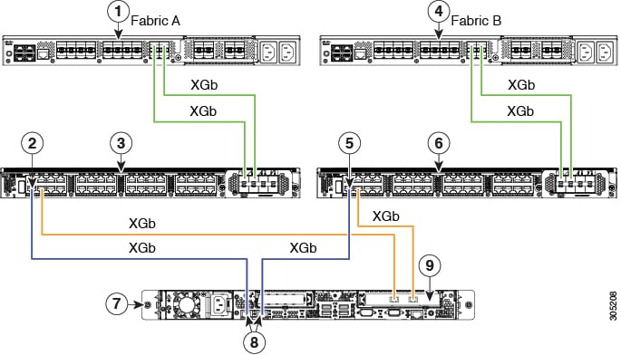
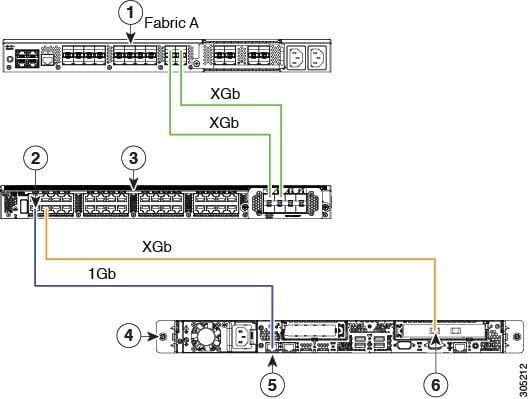
Cisco UCS Manager supports the existing rack server integration and management option through Shared LOM, using two separate cables for data traffic and management traffic. The prerequisites for integration with Cisco UCS Manager are built into the C-Series servers. Make sure you have correct server firmware for integration with Cisco UCS Manager. If not, upgrade your server firmware before integrating the server with Cisco UCS Manager. See Cisco UCS Host Upgrade Utility, User Guide.

Requirements or Dual_Wire Integration with Cisco UCS Manager

Requirements for Cluster Setup

You must have the following items to create a dual-wire integration for C-Series Rack-Mount Server with Cisco UCS Manager in cluster setup:

  • A Cisco UCS system that is running Cisco UCS Manager.

  • Any of the C-Series Rack-Mount Servers and corresponding Cisco IMC and UCS Manager release versions listed in #reference_fjd_t1s_b2b__.

  • Two Cisco UCS VIC cards and two Cisco UCS FIs. See Cisco UCS Fabric Interconnect Server Compatibility Matrix for adapter and FI compatibility with your server. To enable SingleConnect for the Cisco UCS Manager integration, you must have a Cisco VIC installed in the specific slot assigned for SingleConnect in the rack server. If the VIC is not in the specific slot, SingleConnect does not work.


Note


Dual-Wire Management is supported only with Cisco VIC adapters and not with third-party adapters.


Minimum Required Version of Cisco IMC, BIOS and Cisco UCS Manager for Dual-Wire Integration

Table 1. Minimum Required Version of Cisco IMC, BIOS and Cisco UCS Manager

Server

Cisco IMC

Cisco IMC BIOS

Cisco UCS Manager

UCS Manager (BIOS)

Cisco UCS C240 M8 Server

4.3(6.250039)

C240M8 4.3.6a.0.0319250402

4.3(6a)

ucs-c240-m8-bios.4.3.6a.0.0319250402

Cisco UCS C220 M8 Server

4.3(6.250039)

C220M8 4.3.6a.0.0319250402

4.3(6a)

ucs-c220-m8-bios.4.3.6a.0.0319250402

Cisco UCS C225 M8 Server

4.3(5.240021)

C225M8.4.3.5a.0.0904241155

4.3(5a)

ucs-c225-m8-bios 4.3.5a.0.0904241155

Cisco UCS C245 M8 Server

4.3(4.241014)

C245M8.4.3.4a.0.0520240849

4.3(4b)

ucs-c245-m8-bios.C245-m8 4.3.4a.0.0520240849

Cisco UCS C240 M7 Server

4.3.1.230097

C240M7.4.3.1a.0

4.3(2b)

ucs-c240-m7-bios.C240M7.4.3.2a.0.0710230213

Cisco UCS C220 M7 Server

4.3.1.230097

C220M7.4.3.1a.0

4.3(2b)

ucs-c220-m7-bios.C220M7.4.3.2a.0.0710230213

Cisco UCS C220 M6 Server

4.2(1)

4.2(1)

4.2(1)

4.2(1)

Cisco UCS C240 M6 Server

4.2(1)

4.2(1)

4.2(1)

4.2(1)

Cisco UCS C220 M5 Server

3.1.1d

3.1.1i.0

3.2(1d)

3.1.1i.0

Cisco UCS C245 M6 Server

4.2(1)

4.2(1)

4.2(1)

4.2(1)

Cisco UCS C240 M5 Server

3.1.1d

3.1.1h.0

3.2(1d)

3.1.1h.0

Cisco UCS C480 M5 Server

3.1(2b)

3.1.2a.0

3.2(2b)

3.1.2a.0

Cisco UCS C480 M5 Server

3.1(2b)

3.1.2a.0

3.2(2b)

3.1.2a.0

Cisco UCS C125 M5 Server

4.0(1a)

4.0(1a)

4.0(1a)

4.0(1a)

Cisco UCS C480 M5 ML Server

4.0(2a)

4.0(2a)

4.0(2a)

4.0(2a)

Cisco UCS C240 SD M5 Server

4.1(2)

4.1(2)

4.1(2)

4.1(2)

Recommended Cisco VIC Firmware Version

Table 2. Recommended Cisco VIC Firmware Version

Server

VIC Firmware Version

Cisco UCS VIC 15238

5.3(2.32)

Cisco UCS VIC 15235

5.3(2.32)-48

Cisco UCS VIC 15425

5.3(2.32)-48

For Cisco UCS VIC 15428 MLOM

5.3(2.32)-48

Cisco UCS VIC 1495

5.3(2.32)

For Cisco UCS VIC 1467 and 1477 MLOM:

5.3(2.32)

For Cisco UCS VIC 1455 and 1457 MLOM:

5.3(2.32)

Cisco UCS VIC 1385 and 1387 MLOM

4.6(2.230015)

Recommended Cisco VIC Slot

Table 3. Cisco UCS VIC Slot

Server

PCIe Slot

Cisco UCS C240 M8 Server

MLOM, 1, 2, 4, and 5

Note


If slots 2 and 5 are occupied with GPUs, then VICs can be placed in slots 1 and 4.

Cisco UCS C220 M8 Server

MLOM, 1, 3

Cisco UCS C225 M8 Server

MLOM, 2 and 5

Note


If slots 2 and 5 are occupied with GPUs, then VICs can be placed in slots 1 and 4.

Cisco UCS C245 M8 Server

MLOM, 2 and 5

Note


If slots 2 and 5 are occupied with GPUs, then VICs can be placed in slots 1 and 4.

Cisco UCS C220 M7 Server

MLOM, 1, 3

Cisco UCS C240 M7 Server

MLOM, 1, 2, 4, and 5

Note


If slots 2 and 5 are occupied with GPUs, then VICs can be placed in slots 1 and 4.

Cisco UCS C220 M6 Server

MLOM, 1, 3

Cisco UCS C240 M6 Server

MLOM, 1, 2, 4, and 5

Note


If slots 2 and 5 are occupied with GPUs, then VICs can be placed in slots 1 and 4.

Cisco UCS C245 M6 Server

MLOM, 1, 2, 4, and 5

Note


If slots 2 and 5 are occupied with GPUs, then VICs can be placed in slots 1 and 4.

Cisco UCS C220 M5 Server

MLOM, 1

For Cisco UCS C220 M5 Server servers you can use either MLOM or VIC to integrate with Cisco UCS Manager in SingleConnect or direct connect mode.

Cisco UCS C240 M5 Server

MLOM, 1, 2, 4, 5

Note


If slots 2 and 5 are occupied with GPUs, then VICs can be placed in slots 1 and 4.

For Cisco UCS C240 M5 Server servers you can use either MLOM or VIC to integrate with Cisco UCS Manager in SingleConnect or direct connect mode.

See Cisco UCS Manager Management for Mixed VIC Set-up for slot combination.

Cisco UCS C240 SD M5 Server

MLOM, 1, 2

Cisco UCS C480 M5 Server

1, 2

Cisco UCS C125 M5 Server

2

Cisco UCS C125 M5 Servers do not support MLOM. For Cisco UCS C125 M5 Servers, you must place the VIC card in slot 2 only.

Cisco UCS C480 M5 Server

1, 2

Cisco UCS C480 M5 ML Server

11, 12

Cabling Considerations

Refer xx for the compatible cables. (release notes link)

Requirements for Non-Cluster Setup

If you are integrating the server in a non-cluster setup, along with the Cisco UCS Manager and C-series rack mount server, you need the following components :

Connecting the C-Series Server with Cisco UCS Domain in Cluster Setup

Connecting the C-Series Server with Cisco UCS Domain in Cluster Setup

To view illustrations on the connectivity for each C-Series Rack-Mount Server, see Physical Connectivity Illustrations for Cluster Setup.


Important


Make sure the server Cisco IMC is set to factory default settings to integrate with Cisco UCS Manager.


Procedure


Step 1

Install the server in the rack. See the Install and Upgrade Guide for the server that you are using. The install guides are available at the following url: Install and Upgrade Guides.

Step 2

To connect the management traffic paths, do the following:

  1. Insert one GLC-T transceiver into a port of the FEX that is connected to Fabric A. You can use any port on the FEX.

  2. Insert one GLC-T transceiver into a port of the FEX that is connected to Fabric B. You can use any port on the FEX.

  3. Connect an RJ-45 Ethernet cable between a 1-Gb port on the rear panel of the server and the transceiver that you inserted into the FEX in Fabric A.

  4. Connect an RJ-45 Ethernet cable between a 1-Gb port on the rear panel of the server and the transceiver that you inserted into the FEX in Fabric B.

Step 3

To connect the data traffic paths, do the following:

  1. Connect a supported SFP cable between the adapter card in the server and a port on a FEX in Fabric A. You can use any port on the FEX.

  2. Connect a supported SFP cable between the adapter card in the server and a port on a FEX in Fabric B. You can use any port on the FEX.

Step 4

Connect the paths from the FEXes to the FIs. These paths carry both data and management traffic.

  1. Connect two a supported SFP cables between FEX A and two ports on FI A. You can use any ports on FI A, but the ports must be enabled for server traffic.

  2. Connect two a supported SFP cables between FEX B and two ports on FI B. You can use any ports on FI B, but the ports must be enabled for server traffic.

    • On the FEX, you can use only the right block of eight ports for uplinks.

    • The maximum number of uplinks is eight. Based on the Cisco UCS Manager FI discovery policy the port cabling requirement between the FEX and FI vary.

    • Do not mix SFP types on an uplink. If you do, you will see Discovery Failed errors.

Step 5

Attach a power cord to each power supply in your server, and then attach the power cord to a grounded AC power outlet.

Step 6

Reboot the server.


Physical Connectivity Illustrations for Cluster Setup

The following image shows a samples of the physical connectivity for C-Series Rack-Mount Server with Cisco UCS Domain, Cisco UCS Manager.

This image shows the cabling configuration for Cisco UCS Manager integration with a C-Series Rack-Mount Server. The paths shown in blue carry management traffic. The paths shown in gold carry data traffic.

Figure 1. Cluster Setup Cabling Configuration


1

Cisco UCS FI (Fabric A)

6

Cisco FEX (Fabric B)

2

Cisco FEX port (Fabric A)

7

C-Series Rack-Mount Server

3

Cisco FEX (Fabric A)

8

1-Gb Ethernet LOM ports

4

Cisco UCS FI (Fabric B)

9

10-Gb Adapter card in supported PCIe or MLOM slot.

5

Cisco FEX port (Fabric B)

Cabling Considerations

Refer xx for the compatible cables. (release notes link)

Connecting the C-Series Server with Cisco UCS Domain in Non-Cluster Setup

Connecting the C-Series Server with UCS Domain in Non-cluster Setup

To connect the C-Series server with the UCS domain, complete the same steps described in Connecting the C-Series Server with UCS Domain in Non-cluster Setup. Instead of connecting two FIs and two FEXes, you will connect only one FI and one FEX.

Figure 2. Dual-wire Non-Cluster Setup Example

The following illustration is an example of non-cluster setup in dual-wire management.


1

Cisco UCS FI (Fabric A)

4

Cisco UCS C-series server

2

Cisco FEX port (Fabric A)

5

1-Gb Ethernet LOM ports

3

FEX (Fabric A)

6

Cisco UCS VIC adapter in supported PCIe slot

Cabling Considerations

Refer xx for the compatible cables. (release notes link)

Managing the Rack-Mount Server in Cisco UCS Manager after Integration

You can manage and monitor all rack-mount servers that have been integrated with a Cisco UCS domain through Cisco UCS Manager. After the integration, you can perform all rack-mount server management tasks only through the service profiles from Cisco UCS Manager GUI or Cisco UCS Manager CLI. The C-Series Rack-Mount Server Cisco IMC is not accessible when you start managing the server with Cisco UCS Manager.

Cisco UCS Manager provides information, errors, and faults for each rack-mount server that was discovered.

For more information on managing C-Series Rack-Mount Servers from Cisco UCS Manager, see the chapter on Managing Rack-Mount Servers in your release specific Cisco UCS Manager Configuration Guide.

Reverting a Server From Cisco UCS Domain Mode to Standalone Mode

When you manage a Cisco UCS C-Series server with Cisco UCS Manager software, a UCS Manager service profile is associated with the server. If you want to revert a C-Series server to standalone mode (so that it can be managed by Cisco IMC software), you must do the following actions in UCS Manager:

Procedure


Step 1

Disassociate the UCS Manager service profile from the server.

Step 2

Remove the connections from the adapter.

Step 3

Manually power on the server.

Step 4

Connect the front panel KVM connection.

Step 5

Press F8 during the boot up.

Step 6

Reset Cisco IMC to factory defaults or stand-alone mode.

Caution


If you do not disassociate the service profile from the server, MAC and WWN numbers assigned by Cisco UCS Manager might be kept by the server. This can cause numbering duplication and conflicts with other servers that are managed by Cisco UCS Manager. Also, if you revert a server to standalone mode without disassociating the service profile, any LSI RAID controller may not show as a bootable device in the standalone server, preventing local booting.


Special Considerations for Integrated Servers

When you connect the C-Series servers in Cisco UCS system, make sure to review the following information:

Supported FEX-to-FI Uplink Cable SFP Types

The C-Series UCSM integration requires six 10-Gb SFP cables for the following purposes:

  • Linking the data traffic paths between server and FEX - 2 cables

  • Uplinks from the FEXes to the FIs - 4 cables

    Each of the four uplinks from the FEXes to the FIs can use either a Cisco 10-Gb twinax cable, or one of the following SFP types:

    • SFP-10GE-SR

    • FET-10GE


Caution


Do not mix SFP types on an uplink. If you mix SFP types on an uplink, you will get Discovery failed errors.


Integrated Server Power States vs Service Profile Power States

Using the power button or Cisco UCS Manager, if you set the desired power status to Down for an integrated C-Series server's associated service profile, when you try to rest the server to the desired power state, the server becomes out of sync with the actual power state. This may cause the server to shut down unexpectedly at a later time.

Use the Boot Server action in Cisco UCS Manager to safely reboot a server from a power-down state.

The following table shows how the physical server power states can differ from the Cisco UCS Manager service profile power states when the power button on the server is used.

Table 4. Difference in Server Power State and Service Profile Power State

Initial Service Profile Power State

Server Initial Power State

Action From Physical Power Button

Actual Server Power State After the Action

Power State Under UCSM Equipment Tab

Desired Power State Under Service Profile

Down

Off

Push button to turn on

On

On

Down

Up

On

Push button to turn off

Off

Off

Up

Cautions and Limitations for Adapter Cards

Make sure to consider the following when using the adapter cards in Cisco UCS C-Series server integration with Cisco UCS Manager:

  • Cisco UCS Manager supports only four UCS managed adapter cards in the integrated Cisco UCS C-series servers, even if the server has more than four PCI slots. If you have more than four adapter cards in the server, after integration, the rack server discovery fails in Cisco UCS Manager.

  • When you add, remove, or replace an adapter card in a UCS-managed server, you must first decommission the server in Cisco UCS Manager. After the operation, you must then recommission the server.

  • If you install more than one adapter in the server each adapter in a cluster UCS Manager environment, each adapter must be connected to both path A and B. Attempting to connect both ports on an adapter to a single path results in a discovery failure due to an unsupported configuration. If you attempt to connect only one link from each adapter to the fabric, the server may reboot during a card failure to rediscover the data pathways. Neither of these scenarios are supported with connectivity options.

FEX Considerations

Re-acknowledge Attached Servers After a FEX Is Decommissioned/Recommissioned

Whenever you decommission or recommission a Cisco UCS FEX, all the servers that are connected to that FEX must be re-acknowledged in UCS Manager.