VersaStack with Cisco UCS and IBM FlashSystem A9000 Storage for 5000 VMware Horizon Users
Available Languages
VersaStack with Cisco UCS and IBM FlashSystem A9000 Storage for 5000 VMware Horizon Users
Deployment Guide for Cisco UCS B200 M4 Blade Servers with IBM FlashSystem A9000 Storage on VMware Horizon 7.0.3 and VMware ESXi 6.0
Last Updated: July 18, 2017

About the Cisco Validated Design (CVD) Program
The CVD program consists of systems and solutions designed, tested, and documented to facilitate faster, more reliable, and more predictable customer deployments. For more information visit
http://www.cisco.com/go/designzone.
ALL DESIGNS, SPECIFICATIONS, STATEMENTS, INFORMATION, AND RECOMMENDATIONS (COLLECTIVELY, "DESIGNS") IN THIS MANUAL ARE PRESENTED "AS IS," WITH ALL FAULTS. CISCO AND ITS SUPPLIERS DISCLAIM ALL WARRANTIES, INCLUDING, WITHOUT LIMITATION, THE WARRANTY OF MERCHANTABILITY, FITNESS FOR A PARTICULAR PURPOSE AND NONINFRINGEMENT OR ARISING FROM A COURSE OF DEALING, USAGE, OR TRADE PRACTICE. IN NO EVENT SHALL CISCO OR ITS SUPPLIERS BE LIABLE FOR ANY INDIRECT, SPECIAL, CONSEQUENTIAL, OR INCIDENTAL DAMAGES, INCLUDING, WITHOUT LIMITATION, LOST PROFITS OR LOSS OR DAMAGE TO DATA ARISING OUT OF THE USE OR INABILITY TO USE THE DESIGNS, EVEN IF CISCO OR ITS SUPPLIERS HAVE BEEN ADVISED OF THE POSSIBILITY OF SUCH DAMAGES.
THE DESIGNS ARE SUBJECT TO CHANGE WITHOUT NOTICE. USERS ARE SOLELY RESPONSIBLE FOR THEIR APPLICATION OF THE DESIGNS. THE DESIGNS DO NOT CONSTITUTE THE TECHNICAL OR OTHER PROFESSIONAL ADVICE OF CISCO, ITS SUPPLIERS OR PARTNERS. USERS SHOULD CONSULT THEIR OWN TECHNICAL ADVISORS BEFORE IMPLEMENTING THE DESIGNS. RESULTS MAY VARY DEPENDING ON FACTORS NOT TESTED BY CISCO.
CCDE, CCENT, Cisco Eos, Cisco Lumin, Cisco Nexus, Cisco StadiumVision, Cisco TelePresence, Cisco WebEx, the Cisco logo, DCE, and Welcome to the Human Network are trademarks; Changing the Way We Work, Live, Play, and Learn and Cisco Store are service marks; and Access Registrar, Aironet, AsyncOS, Bringing the Meeting To You, Catalyst, CCDA, CCDP, CCIE, CCIP, CCNA, CCNP, CCSP, CCVP, Cisco, the Cisco Certified Internetwork Expert logo, Cisco IOS, Cisco Press, Cisco Systems, Cisco Systems Capital, the Cisco Systems logo, Cisco Unified Computing System (Cisco UCS), Cisco UCS B-Series Blade Servers, Cisco UCS C-Series Rack Servers, Cisco UCS S-Series Storage Servers, Cisco UCS Manager, Cisco UCS Management Software, Cisco Unified Fabric, Cisco Application Centric Infrastructure, Cisco Nexus 9000 Series, Cisco Nexus 7000 Series. Cisco Prime Data Center Network Manager, Cisco NX-OS Software, Cisco MDS Series, Cisco Unity, Collaboration Without Limitation, EtherFast, EtherSwitch, Event Center, Fast Step, Follow Me Browsing, FormShare, GigaDrive, HomeLink, Internet Quotient, IOS, iPhone, iQuick Study, LightStream, Linksys, MediaTone, MeetingPlace, MeetingPlace Chime Sound, MGX, Networkers, Networking Academy, Network Registrar, PCNow, PIX, PowerPanels, ProConnect, ScriptShare, SenderBase, SMARTnet, Spectrum Expert, StackWise, The Fastest Way to Increase Your Internet Quotient, TransPath, WebEx, and the WebEx logo are registered trademarks of Cisco Systems, Inc. and/or its affiliates in the United States and certain other countries.
All other trademarks mentioned in this document or website are the property of their respective owners. The use of the word partner does not imply a partnership relationship between Cisco and any other company. (0809R)
© 2017 Cisco Systems, Inc. All rights reserved.
Table of Contents
Cisco Desktop Virtualization Solutions: Data Center
Cisco Desktop Virtualization Focus
Cisco Unified Computing System
Cisco Unified Computing System Components
Cisco UCS B200 M4 Blade Server
Cisco UCS VIC1340 Converged Network Adapter
Cisco Nexus 1000V Distributed Virtual Switch
Cisco MDS 9148S Fiber Channel Switch
Advantages of Using VMware Horizon
What are VMware RDS Hosted Sessions?
Farms, RDS Hosts, and Desktop and Application Pools
Supported Windows 10 Operating Systems
Desktop Virtualization Design Fundamentals
VMware Horizon Design Fundamentals
Horizon VDI Pool and RDSH Servers Pool
IBM FlashSystem Grid Controller
IBM FlashSystem Flash Enclosure
Spectrum Accelerate Feature Set
Benefits of IBM FlashSystem A9000 Series
Architecture and Design Considerations for Desktop Virtualization.
Understanding Applications and Data
Project Planning and Solution Sizing Sample Questions
Designing a VMware Horizon Environment for a Mixed Workload
Solution Hardware and Software
Configuration Topology for Scalable VMware Horizon Mixed Workload
Cisco Unified Computing System Base Configuration
Cisco UCS Manager Software Version 3.1(2b)
Configure Fabric Interconnects at Console
Base Cisco UCS System Configuration
Set Fabric Interconnects to Fibre Channel End Host Mode
Configure Fibre Channel Uplink Ports
Enable Server and Ethernet Uplink Ports
Create Uplink Port Channels to Cisco Nexus 9372PX Switches
Create Uplink Port Channels to Cisco MDS 9148S Switches
Create Required Shared Resource Pools
Set Jumbo Frames in Cisco UCS Fabric
Create Network Control Policy for Cisco Discovery Protocol
Cisco UCS System Configuration for Cisco UCS B-Series
IBM FlashSystem A9000 Configuration for Cisco Validated Design
IBM FlashSystem A9000 Configuration
Connectivity to Cisco MDS 9148S
How to Install IBM Hyper-Scale Manager
Hyper-Scale Manger Installation
Configure Hyper-Scale Manager for the FlashSystem A9000
IBM FlashSystem A9000 Data Storage Layout
Create Volume and Data Stores on IBM FlashSystem A9000
Configure User Profile Manager Share on IBM FlashSystem A9000
Installing and Configuring VMware ESXi 6.0
Install and Configure VMware vCenter Appliance
Install and Configure VSUM and Cisco Nexus 1000v
Install Cisco Virtual Switch Update Manager
Install Cisco Virtual Switch Update Manager
Install Cisco Nexus 1000V using Cisco VSUM
Perform Base Configuration of the Primary VSM
Add VMware ESXi Hosts to Cisco Nexus 1000V
Building the Virtual Machines and Environment for Workload Testing
Software Infrastructure Configuration
Installing and Configuring VMware Horizon Environment
VMware Horizon Connection Server Configuration
Horizon VMware Replica Server Creation
Install VMware Horizon Composer Server
Create the Golden Image for VMware Horizon RDS Deployment
Create the Golden Image for Horizon Linked Clone Desktops
VMware Horizon Agent Installation
VMware Horizon Desktop Pool Creation
Configuring User Profile Management
Cisco UCS Configuration for Cluster Testing
Cisco UCS Configuration for Full Scale Testing
Testing Methodology and Success Criteria
Pre-Test Setup for Single and Multi-Blade Testing
Server-Side Response Time Measurements
Single-Server Recommended Maximum Workload
Single-Server Recommended Maximum Workload Testing
Single-Server Recommended Maximum Workload for RDS Hosted Server Sessions: 230 Users
Single-Server Recommended Maximum Workload for VDI Non-Persistent with 155 Users
Cluster Workload Testing with 2100 RDS Users
Performance Data from One RDSH Server: 2100 Users RDSH Sessions Cluster Testing
Cluster Workload Testing with 2900 Non-Persistent VDI Desktop Users
Full Scale Mixed Workload Testing with 5000 Users
IBM FlashSystem A9000 Storage Detailed Test Results for Cluster Scalability Test
IBM FlashSystem A9000 Storage Test Results for 2100 RDS Windows 2012 Sessions
2100 RDSH Cluster Test: Storage Charts
IBM FlashSystem Storage Test Results for 5000 User Full Scale, Mixed Workload Scalability
Scalability Considerations and Guidelines
Scalability of VMware Horizon 7 Configuration
Get More Business Value with Services
Cisco UCS Manager Configuration Guides
Cisco UCS Virtual Interface Cards
Cisco Nexus Switching References
Cisco MDS 9000 Service Switch References
IBM Storage Reference Documents
Appendix A – Cisco Nexus Ethernet and MDS Fibre Channel Switch Configurations
Ethernet Network Configuration
Cisco Nexus 9372PX-A Configuration
Cisco Nexus 9172PX-B Configuration
Fibre Channel Network Configuration
Cisco MDS 9148S-A Configuration
Cisco MDS 9148S-B Configuration
Simulation 1: 2100 RDSH Server Sessions Cluster Testing | RDSH Host Metrics
Simulation 2: 2900 Windows 10 x64 Non-Persistent VMware Horizon Cluster Test
ESX CPU Util% for All RDSH Hosts on 5000 Users Scale Test
Sample RDS Servers Perfmon Metrics for 5000 Users Mixed Scale Test
Sample VDI Host Metrics for 5000 Users Scale Test
IBM A9000 Storage Charts for 5000 Users Scale Test
5000 Users Mixed Scale Test Boot Phase (Sample metrics: 2 RDS Hosts and 4 VDI Hosts)
Cisco® Validated Designs include systems and solutions that are designed, tested, and documented to facilitate and improve customer deployments. These designs incorporate a wide range of technologies and products into a portfolio of solutions that have been developed to address the business needs of customers. Cisco and IBM have partnered to deliver this document, which serves as a specific step by step guide for implementing this solution. This Cisco Validated Design provides an efficient architectural design that is based on customer requirements. The solution that follows is a validated approach for deploying Cisco and IBM technologies as a shared, high performance, resilient, virtual desktop infrastructure.
This document provides a reference architecture and design guide for up to 5000 seat mixed workload on Cisco UCS and IBM FlashSystem A9000 storage VMware Horizon server-based Remote Desktop Sever Hosted Sessions and VMware Horizon non-persistent Microsoft Windows 10 virtual desktops on VMware vSphere 6. The solution is a predesigned, best-practice data center architecture built on the Cisco Unified Computing System (UCS), the Cisco Nexus® 9000 family of switches, Cisco MDS 9000 family of Fibre Channel switches and an IBM all flash array.
This solution is 100 percent virtualized on Cisco UCS B200 M4 blade servers, booting VMware vSphere 6.0 Update 2 via fibre channel SAN from the IBM FlashSystem A9000 storage array. The virtual desktop sessions are powered by VMware Horizon 7 floating assignment linked clone virtual Windows 10 desktops and hosted shared 2012 R2 server desktops, providing unparalleled scale and management simplicity. VMware Horizon Remote Desktop Server Hosted Sessions (2100 RDS Server sessions) and VMware Horizon linked clone Window 10 desktops (2900 virtual desktops) were provisioned on the IBM FlashSystem A9000 storage array. Where applicable the document provides best practice recommendations and sizing guidelines for customer deployment of this solution.
The solution provides outstanding virtual desktop end user experience as measured by the Login VSI 4.1 Knowledge Worker workload running in benchmark mode.
The 5000 seat solution provides a large scale building block that can be replicated to confidently scale out to tens of thousands of users.
Introduction
The current industry trend in data center design is towards shared infrastructures. By using virtualization along with pre-validated IT platforms, enterprise customers have embarked on the journey to the cloud by moving away from application silos and toward shared infrastructure that can be quickly deployed, thereby increasing agility and reducing costs. Cisco, IBM Storage and VMware have partnered to deliver this Cisco Validated Design, which uses best of breed storage, server and network components to serve as the foundation for desktop virtualization workloads, enabling efficient architectural designs that can be quickly and confidently deployed.
Audience
The audience for this document includes, but is not limited to; sales engineers, field consultants, professional services, IT managers, partner engineers, and customers who want to take advantage of an infrastructure built to deliver IT efficiency and enable IT innovation.
Purpose of this Document
This document provides a step by step design, configuration and implementation guide for the Cisco Validated Design for a large scale VMware Horizon 7 mixed workload solution with IBM FlashSystem A9000 storage, Cisco UCS Blade Servers, Cisco Nexus 9000 series ethernet switches and Cisco MDS 9000 series fibre channel switches.
What’s New?
This is the first desktop virtualization Cisco Validated Design with IBM Storage.
It incorporates the following features:
· Validation of Cisco Nexus 9000 with a IBM Storage all flash storage array
· Validation of Cisco MDS 9000 with a IBM Storage all flash storage array
· Support for the Cisco UCS 3.1(1) release and Cisco UCS B200-M4 servers
· Support for the latest release of IBM FlashSystem A9000 hardware and Spectrum Accelerate Operating Environment 12.0.2.c
· A Fibre Channel storage design supporting SAN LUNs
· Cisco Nexus 1000v distributed virtual switch technology
· Cisco UCS Inband KVM Access
· Cisco UCS vMedia client for vSphere Installation
· Cisco UCS Firmware Auto Sync Server policy
· VMware vSphere 6.0 Hypervisor
· VMware Horizon 7 RDS Hosted server session
· VMware Horizon 7 non-persistent Windows 10 virtual machines
· The data center market segment is shifting toward heavily virtualized private, hybrid and public cloud computing models running on industry-standard systems. These environments require uniform design points that can be repeated for ease of management and scalability.
The factors have led to the need for predesigned computing, networking and storage building blocks optimized to lower the initial design cost, simplify management, and enable horizontal scalability and high levels of utilization.
The use cases include:
· Enterprise Data Center
· Service Provider Data Center
This Cisco Validated Design prescribes a defined set of hardware and software that serves as an integrated foundation for both VMware Horizon RDSH server desktop sessions based on Microsoft Server 2012 R2 and VMware Horizon VDI non–persistent virtual machines based on Windows 10 Operating System. The mixed workload solution includes IBM FlashSystem storage, Cisco Nexus® and MDS networking, the Cisco Unified Computing System (Cisco UCS®), VMware Horizon and VMware vSphere software in a single package. The design is space optimized such that the network, compute, and storage required can be housed in one data center rack. Switch port density enables the networking components to accommodate multiple compute and storage configurations of this kind.
The infrastructure is deployed to provide Fibre Channel-booted hosts with block-level access to shared storage. The reference architecture reinforces the "wire-once" strategy, because as additional storage is added to the architecture, no re-cabling is required from the hosts to the Cisco UCS fabric interconnect.
The combination of technologies from Cisco Systems, Inc., International Business Machines Corp. and VMware Inc. produced a highly efficient, robust and affordable desktop virtualization solution for a hosted virtual desktop and hosted shared desktop mixed deployment supporting different use cases. Key components of the solution include the following:
· More power, same size. Cisco UCS B200 M4 half-width blade with dual 14-core 2.4 GHz Intel Xeon (E5-2680v4) processors and 512GB of memory for VMware Horizon Desktop hosts supports more virtual desktop workloads than the previously released generation processors on the same hardware. The Intel Xeon E5-2680 v4 14-core processors used in this study provided a balance between increased per-blade capacity and cost.
· Fault-tolerance with high availability built into the design. The various designs are based on using one Unified Computing System chassis with multiple Cisco UCS B200 M4 blades for virtualized desktop and infrastructure workloads. The design provides N+1 server fault tolerance for hosted virtual desktops, hosted shared desktops and infrastructure services.
· Stress-tested to the limits during aggressive boot scenario. The 5000-user mixed RDS hosted virtual sessions and VDI pooled shared desktop environment booted and registered with the VMware Horizon 7 Administrator in under 20 minutes, providing our customers with an extremely fast, reliable cold-start desktop virtualization system.
· Stress-tested to the limits during simulated login storms. All 5000 simulated users logged in and started running workloads up to steady state in 48-minutes without overwhelming the processors, exhausting memory or exhausting the storage subsystems, providing customers with a desktop virtualization system that can easily handle the most demanding login and startup storms.
· Ultra-condensed computing for the datacenter. The rack space required to support the system is less than a single 42U rack, conserving valuable data center floor space.
· All Virtualized: This Cisco Validated Design (CVD) presents a validated design that is 100 percent virtualized on VMware ESXi 6.0. All of the virtual desktops, user data, profiles, and supporting infrastructure components, including Active Directory, Provisioning Servers, SQL Servers, VMware Horizon Connection Servers, VMware Horizon Composer Server, VMware Horizon Replica Servers, VMware Horizon Remote Desktop Server Hosted sessions and VDI virtual machine desktops. This provides customers with complete flexibility for maintenance and capacity additions because the entire system runs on the VersaStack converged infrastructure with stateless Cisco UCS Blade servers and IBM fibre channel storage.
· Cisco maintains industry leadership with the new Cisco UCS Manager 3.1(1) software that simplifies scaling, guarantees consistency, and eases maintenance. Cisco’s ongoing development efforts with Cisco UCS Manager, Cisco UCS Central, and Cisco UCS Director insure that customer environments are consistent locally, across Cisco UCS Domains and across the globe, our software suite offers increasingly simplified operational and deployment management, and it continues to widen the span of control for customer organizations’ subject matter experts in compute, storage and network.
· Our 10G unified fabric story gets additional validation on Cisco UCS 6200 Series Fabric Interconnects as Cisco runs more challenging workload testing, while maintaining unsurpassed user response times.
· IBM FlashSystem A9000 Storage Array provides industry-leading storage solutions that efficiently handle the most demanding I/O bursts (for example, login storms), profile management, and user data management, deliver simple and flexible business continuance, and help reduce storage cost per desktop.
· IBM FlashSystem A9000 Storage Array provides a simple to understand storage architecture for hosting all user data components (VMs, profiles, user data) on the same storage array.
· IBM FlashSystem A9000 Storage Array Operating System enables users to seamlessly add, upgrade or remove storage from the infrastructure to meet the needs of the virtual desktops.
· IBM FlashSystem A9000 Storage Array for VMware vSphere hypervisor has deep integrations with vSphere, providing easy-button automation for key storage tasks such as storage repository provisioning and storage resize directly from the VCenter web client in a single pane of glass.
· Latest and greatest virtual desktop and application product. VMware Horizon 7 follows a new unified product architecture that supports both hosted-shared desktops and applications (RDS) and complete virtual desktops (VDI). This new VMware Horizon release simplifies tasks associated with large-scale VDI management. This modular solution supports seamless delivery of Windows apps and desktops as the number of users increase. In addition, Horizon enhancements help to optimize performance and improve the user experience across a variety of endpoint device types, from workstations to mobile devices including laptops, tablets, and smartphones.
· Optimized to achieve the best possible performance and scale. For hosted shared desktop sessions, the best performance was achieved when the number of vCPUs assigned to the VMware 7 RDS virtual machines did not exceed the number of hyper-threaded (logical) cores available on the server. In other words, maximum performance is obtained when not overcommitting the CPU resources for the virtual machines running virtualized RDS systems.
· Provisioning desktop machines made easy. Remote Desktop Server Hosted (RDSH) shared virtual machines and VMware Horizon 7, Microsoft Windows 10, virtual machines were created for this solution using a single method for both the VMware Composer pooled desktops.
Cisco Desktop Virtualization Solutions: Data Center
The Evolving Workplace
Today’s IT departments are facing a rapidly evolving workplace environment. The workforce is becoming increasingly diverse and geographically dispersed, including offshore contractors, distributed call center operations, knowledge and task workers, partners, consultants, and executives connecting from locations around the world at all times.
This workforce is also increasingly mobile, conducting business in traditional offices, conference rooms across the enterprise campus, home offices, on the road, in hotels, and at the local coffee shop. This workforce wants to use a growing array of client computing and mobile devices that they can choose based on personal preference. These trends are increasing pressure on IT to ensure protection of corporate data and prevent data leakage or loss through any combination of user, endpoint device, and desktop access scenarios (Figure 1).
These challenges are compounded by desktop refresh cycles to accommodate aging PCs and bounded local storage and migration to new operating systems, specifically Microsoft Windows 10 and productivity tools, specifically Microsoft Office 2016.
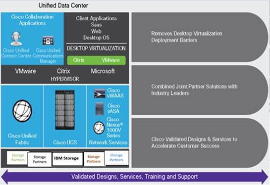
Figure 1 Cisco Data Center Partner Collaboration
Some of the key drivers for desktop virtualization are increased data security and reduced TCO through increased control and reduced management costs.
Cisco Desktop Virtualization Focus
Cisco focuses on three key elements to deliver the best desktop virtualization data center infrastructure: simplification, security, and scalability. The software combined with platform modularity provides a simplified, secure, and scalable desktop virtualization platform.
Simplified
Cisco UCS provides a radical new approach to industry-standard computing and provides the core of the data center infrastructure for desktop virtualization. Among the many features and benefits of Cisco UCS are the drastic reduction in the number of servers needed and in the number of cables used per server, and the capability to rapidly deploy or reprovision servers through Cisco UCS service profiles. With fewer servers and cables to manage and with streamlined server and virtual desktop provisioning, operations are significantly simplified. Thousands of desktops can be provisioned in minutes with Cisco UCS Manager service profiles and Cisco storage partners’ storage-based cloning. This approach accelerates the time to productivity for end users, improves business agility, and allows IT resources to be allocated to other tasks.
Cisco UCS Manager automates many mundane, error-prone data center operations such as configuration and provisioning of server, network, and storage access infrastructure. In addition, Cisco UCS B-Series Blade Servers and C-Series Rack Servers with large memory footprints enable high desktop density that helps reduce server infrastructure requirements.
Simplification also leads to more successful desktop virtualization implementation. Cisco and its technology partners like VMware Technologies and IBM have developed integrated, validated architectures, including predefined converged architecture infrastructure packages such as VersaStack. Cisco Desktop Virtualization Solutions have been tested with VMware vSphere, VMware Horizon.
Secure
Although virtual desktops are inherently more secure than their physical predecessors, they introduce new security challenges. Mission-critical web and application servers using a common infrastructure such as virtual desktops are now at a higher risk for security threats. Inter–virtual machine traffic now poses an important security consideration that IT managers need to address, especially in dynamic environments in which virtual machines, using VMware vMotion, move across the server infrastructure.
Desktop virtualization, therefore, significantly increases the need for virtual machine–level awareness of policy and security, especially given the dynamic and fluid nature of virtual machine mobility across an extended computing infrastructure. The ease with which new virtual desktops can proliferate magnifies the importance of a virtualization-aware network and security infrastructure. Cisco data center infrastructure (Cisco UCS and Cisco Nexus Family solutions) for desktop virtualization provides strong data center, network, and desktop security, with comprehensive security from the desktop to the hypervisor. Security is enhanced with segmentation of virtual desktops, virtual machine–aware policies and administration, and network security across the LAN and WAN infrastructure.
Scalable
Growth of a desktop virtualization solution is all but inevitable, so a solution must be able to scale, and scale predictably, with that growth. The Cisco Desktop Virtualization Solutions support high virtual-desktop density (desktops per server), and additional servers scale with near-linear performance. Cisco data center infrastructure provides a flexible platform for growth and improves business agility. Cisco UCS Manager service profiles allow on-demand desktop provisioning and make it just as easy to deploy dozens of desktops as it is to deploy thousands of desktops.
Cisco UCS servers provide near-linear performance and scale. Cisco UCS implements the patented Cisco Extended Memory Technology to offer large memory footprints with fewer sockets (with scalability to up to 1 terabyte (TB) of memory with 2- and 4-socket servers). Using unified fabric technology as a building block, Cisco UCS server aggregate bandwidth can scale to up to 80 Gbps per server, and the northbound Cisco UCS fabric interconnect can output 2 terabits per second (Tbps) at line rate, helping prevent desktop virtualization I/O and memory bottlenecks. Cisco UCS, with its high-performance, low-latency unified fabric-based networking architecture, supports high volumes of virtual desktop traffic, including high-resolution video and communications traffic. In addition, Cisco storage partners IBM help maintain data availability and optimal performance during boot and login storms as part of the Cisco Desktop Virtualization Solutions. Recent Cisco Validated Designs based on VMware Horizon, Cisco UCS, and IBM joint solutions have demonstrated scalability and performance, with up to 5000 desktops up and running in 20 minutes.
Cisco UCS and Cisco Nexus data center infrastructure provides an excellent platform for growth, with transparent scaling of server, network, and storage resources to support desktop virtualization, data center applications, and cloud computing.
Savings and Success
The simplified, secure, scalable Cisco data center infrastructure for desktop virtualization solutions saves time and money compared to alternative approaches. Cisco UCS enables faster payback and ongoing savings (better ROI and lower TCO) and provides the industry’s greatest virtual desktop density per server, reducing both capital expenditures (CapEx) and operating expenses (OpEx). The Cisco UCS architecture and Cisco Unified Fabric also enables much lower network infrastructure costs, with fewer cables per server and fewer ports required. In addition, storage tiering and deduplication technologies decrease storage costs, reducing desktop storage needs by up to 50 percent.
The simplified deployment of Cisco UCS for desktop virtualization accelerates the time to productivity and enhances business agility. IT staff and end users are more productive more quickly, and the business can respond to new opportunities quickly by deploying virtual desktops whenever and wherever they are needed. The high-performance Cisco systems and network deliver a near-native end-user experience, allowing users to be productive anytime and anywhere.
The ultimate measure of desktop virtualization for any organization is its efficiency and effectiveness in both the near term and the long term. The Cisco Desktop Virtualization Solutions are very efficient, allowing rapid deployment, requiring fewer devices and cables, and reducing costs. The solutions are also very effective, providing the services that end users need on their devices of choice while improving IT operations, control, and data security. Success is bolstered through Cisco’s best-in-class partnerships with leaders in virtualization and storage, and through tested and validated designs and services to help customers throughout the solution lifecycle. Long-term success is enabled through the use of Cisco’s scalable, flexible, and secure architecture as the platform for desktop virtualization.
Physical Topology
Figure 2 illustrates the physical architecture.
Figure 2 Physical Architecture
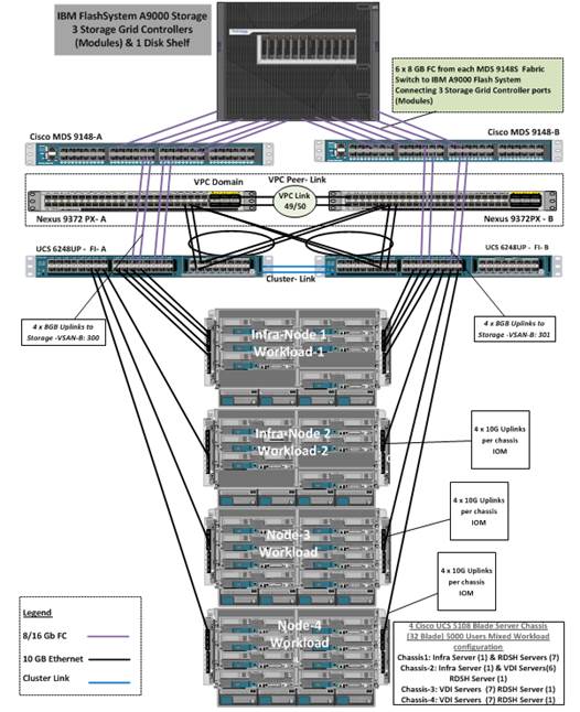
The reference hardware configuration includes:
· Two Cisco Nexus 9372PX switches
· Two Cisco MDS 9148S 16GB Fibre Channel switches
· Two Cisco UCS 6248UP Fabric Interconnects
· Four Cisco UCS 5108 Blade Chassis
· Thirty two Cisco UCS B200 M4 Blade Servers (2 Infra Server hosting Infrastructure VMs and 30 servers for workload)
· One IBM FlashSystem A9000 storage array
For desktop virtualization, the deployment includes VMware Horizon 7 running on VMware vSphere 6. The design is intended to provide a large scale building block for both VMware Horizon RDS Hosted server sessions and Windows 10 non-persistent VDI desktops in the following ratio:
· 2100 Remote Desktop Server Hosted (RDSH) desktop sessions
· 2900 VMware Horizon Windows 10 non-persistent virtual desktops
The data provided in this document will allow our customers to adjust the mix of RDS and VDI desktops to suite their environment. For example, additional blade chassis can be deployed to increase compute capacity, additional disk shelves can be deployed to improve I/O capability and throughput, and special hardware or software features can be added to introduce new features. This document guides you through the detailed steps for deploying the base architecture. This procedure covers everything from physical cabling to network, compute and storage device configurations.
Configuration Guidelines
This Cisco Validated Design provides details for deploying a fully redundant, highly available 5000 seat mixed workload virtual desktop solution with VMware and IBM Storage. Configuration guidelines are provided that refer the reader to which redundant component is being configured with each step. For example, grid controller 01, grid controller 02 and grid controller 03 are used to identify the three IBM FlashSystem A9000 Storage controllers/controllers that are provisioned with this document, Cisco Nexus A or Cisco Nexus B identifies the pair of Cisco Nexus switches that are configured and Cisco MDS A or Cisco MDS B identifies the pair of Cisco MDS switches that are configured. The Cisco UCS 6248UP Fabric Interconnects are similarly configured. Additionally, this document details the steps for provisioning multiple Cisco UCS hosts, and these are identified sequentially: VM-Host-Infra-01, VM-Host-Infra-02, VM-Host-RDSH-01, VM-Host-VDI-01 and so on. Finally, to indicate that you should include information pertinent to your environment in a given step, <text> appears as part of the command structure.
This section describes the components used in the solution outlined in this study.
Cisco Unified Computing System
Cisco UCS Manager provides unified, embedded management of all software and hardware components of the Cisco Unified Computing System™ (Cisco UCS) through an intuitive GUI, a command-line interface (CLI), and an XML API. The manager provides a unified management domain with centralized management capabilities and can control multiple chassis and thousands of virtual machines.
Cisco UCS is a next-generation data center platform that unites computing, networking, and storage access. The platform, optimized for virtual environments, is designed using open industry-standard technologies and aims to reduce total cost of ownership (TCO) and increase business agility. The system integrates a low-latency; lossless 10 Gigabit Ethernet unified network fabric with enterprise-class, x86-architecture servers. It is an integrated, scalable, multi-chassis platform in which all resources participate in a unified management domain.
Cisco Unified Computing System Components
The main components of Cisco UCS are:
· Compute: The system is based on an entirely new class of computing system that incorporates blade servers based on Intel® Xeon® processor E5-2600/4600 v3 and E7-2800 v3 family CPUs.
· Network: The system is integrated on a low-latency, lossless, 10-Gbps unified network fabric. This network foundation consolidates LANs, SANs, and high-performance computing (HPC) networks, which are separate networks today. The unified fabric lowers costs by reducing the number of network adapters, switches, and cables needed, and by decreasing the power and cooling requirements.
· Virtualization: The system unleashes the full potential of virtualization by enhancing the scalability, performance, and operational control of virtual environments. Cisco security, policy enforcement, and diagnostic features are now extended into virtualized environments to better support changing business and IT requirements.
· Storage access: The system provides consolidated access to local storage, SAN storage, and network-attached storage (NAS) over the unified fabric. With storage access unified, Cisco UCS can access storage over Ethernet, Fibre Channel, Fibre Channel over Ethernet (FCoE), and Small Computer System Interface over IP (iSCSI) protocols. This capability provides customers with choice for storage access and investment protection. In addition, server administrators can preassign storage-access policies for system connectivity to storage resources, simplifying storage connectivity and management and helping increase productivity.
· Management: Cisco UCS uniquely integrates all system components, enabling the entire solution to be managed as a single entity by Cisco UCS Manager. The manager has an intuitive GUI, a CLI, and a robust API for managing all system configuration processes and operations.
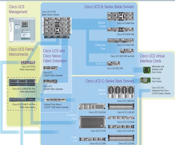
Figure 3 Cisco Data Center Overview
Cisco UCS is designed to deliver:
· Reduced TCO and increased business agility
· Increased IT staff productivity through just-in-time provisioning and mobility support
· A cohesive, integrated system that unifies the technology in the data center; the system is managed, serviced, and tested as a whole
· Scalability through a design for hundreds of discrete servers and thousands of virtual machines and the capability to scale I/O bandwidth to match demand
· Industry standards supported by a partner ecosystem of industry leaders
Cisco UCS Manager provides unified, embedded management of all software and hardware components of the Cisco Unified Computing System across multiple chassis, rack servers, and thousands of virtual machines. Cisco UCS Manager manages Cisco UCS as a single entity through an intuitive GUI, a command-line interface (CLI), or an XML API for comprehensive access to all Cisco UCS Manager Functions.
Cisco UCS Fabric Interconnect
The Cisco UCS 6200 Series Fabric Interconnects are a core part of Cisco UCS, providing both network connectivity and management capabilities for the system. The Cisco UCS 6200 Series offers line-rate, low-latency, lossless 10 Gigabit Ethernet, FCoE, and Fibre Channel functions.
The fabric interconnects provide the management and communication backbone for the Cisco UCS B-Series Blade Servers and Cisco UCS 5100 Series Blade Server Chassis. All chassis, and therefore all blades, attached to the fabric interconnects become part of a single, highly available management domain. In addition, by supporting unified fabric, the Cisco UCS 6200 Series provides both LAN and SAN connectivity for all blades in the domain.
For networking, the Cisco UCS 6200 Series uses a cut-through architecture, supporting deterministic, low-latency, line-rate 10 Gigabit Ethernet on all ports, 1-terabit (Tb) switching capacity, and 160 Gbps of bandwidth per chassis, independent of packet size and enabled services. The product series supports Cisco low-latency, lossless, 10 Gigabit Ethernet unified network fabric capabilities, increasing the reliability, efficiency, and scalability of Ethernet networks. The fabric interconnects support multiple traffic classes over a lossless Ethernet fabric, from the blade server through the interconnect. Significant TCO savings come from an FCoE-optimized server design in which network interface cards (NICs), host bus adapters (HBAs), cables, and switches can be consolidated.
Figure 4 Cisco UCS 6200 Series Fabric Interconnect
Cisco UCS B200 M4 Blade Server
The Cisco UCS B200 M4 Blade Server (Figure 5 and Figure 6) is a density-optimized, half-width blade server that supports two CPU sockets for Intel Xeon processor E5-2600 v3 series CPUs and up to 24 DDR4 DIMMs. It supports one modular LAN-on-motherboard (LOM) dedicated slot for a Cisco virtual interface card (VIC) and one mezzanine adapter. In additions, the Cisco UCS B200 M4 supports an optional storage module that accommodates up to two SAS or SATA hard disk drives (HDDs) or solid-state disk (SSD) drives. You can install up to eight Cisco UCS B200 M4 servers in a chassis, mixing them with other models of Cisco UCS blade servers in the chassis if desired. Latest features of Cisco UCS Virtual Interface Cards (VICs)
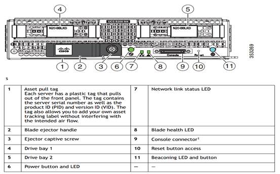
Figure 5 Cisco UCS B200 M4 Front View
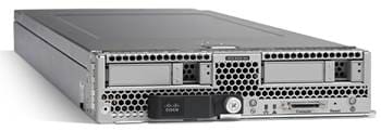
Figure 6 Cisco UCS B200 M4 Back View
Cisco UCS combines Cisco UCS B-Series Blade Servers and C-Series Rack Servers with networking and storage access into a single converged system with simplified management, greater cost efficiency and agility, and increased visibility and control. The Cisco UCS B200 M4 Blade Server is one of the newest servers in the Cisco UCS portfolio.
The Cisco UCS B200 M4 delivers performance, flexibility, and optimization for data centers and remote sites. This enterprise-class server offers market-leading performance, versatility, and density without compromise for workloads ranging from web infrastructure to distributed databases. The Cisco UCS B200 M4 can quickly deploy stateless physical and virtual workloads with the programmable ease of use of the Cisco UCS Manager software and simplified server access with Cisco® Single Connect technology. Based on the Intel Xeon processor E5-2600 v3 and v4 product family, it offers up to 1.5TB of memory using 64GB DIMMs, up to two disk drives, and up to 80 Gbps of I/O throughput. The Cisco UCS B200 M4 offers exceptional levels of performance, flexibility, and I/O throughput to run your most demanding applications.
In addition, Cisco UCS has the architectural advantage of not having to power and cool excess switches, NICs, and HBAs in each blade server chassis. With a larger power budget per blade server, it provides uncompromised expandability and capabilities, as in the new Cisco UCS B200 M4 server with its leading memory-slot capacity and drive capacity.
Cisco UCS B200 M4 Features
The Cisco UCS B200 M4 provides:
· Up to two multicore Intel Xeon processor E5-2600 v3 series CPUs for up to 36 processing cores
· 24 DIMM slots for industry-standard DDR4 memory at speeds up to 2133 MHz, and up to 768 GB of total memory when using 32-GB DIMMs
· Two optional, hot-pluggable SAS and SATA HDDs or SSDs
· Cisco UCS VIC 1340, a 2-port, 40 Gigabit Ethernet and FCoE–capable modular (mLOM) mezzanine adapter
· Provides two 40-Gbps unified I/O ports or two sets of four 10-Gbps unified I/O port
· Delivers 80 Gbps to the server
· Adapts to either 10- or 40-Gbps fabric connections
- Cisco FlexStorage local drive storage subsystem, with flexible boot and local storage capabilities that allow you to
- Configure the Cisco UCS B200 M4 to meet your local storage requirements without having to buy, power, and cool components that you do not need
- Choose an enterprise-class RAID controller, or go without any controller or drive bays if you are not using local drives
- Easily add, change, and remove Cisco FlexStorage modules
The Cisco UCS B200 M4 server is a half-width blade. Up to eight can reside in the 6-rack-unit (6RU) Cisco UCS 5108 Blade Server Chassis, offering one of the highest densities of servers per rack unit of blade chassis in the industry.
Cisco UCS B200 M4 Benefits
The Cisco UCS B200 M4 server is well suited for a broad spectrum of IT workloads, including:
· IT and web infrastructure
· Virtualized workloads
· Consolidating applications
· Virtual desktops
· Middleware
· Enterprise resource planning (ERP) and customer-relationship management (CRM) applications
Innovative Technologies
The Cisco UCS B200 M4 is one member of the Cisco UCS B-Series Blade Servers platform. As part of Cisco UCS, Cisco UCS B-Series servers incorporate many innovative Cisco technologies to help customers handle their most challenging workloads. Cisco UCS B-Series servers within a Cisco UCS management framework incorporate a standards-based unified network fabric, Cisco Data Center Virtual Machine Fabric Extender (VM-FEX) virtualization support, Cisco UCS Manager, Cisco UCS Central Software, Cisco UCS Director software, and Cisco fabric extender architecture.
The Cisco UCS B200 M4 Blade Server delivers:
· Suitability for a wide range of applications and workload requirements
· Highest-performing CPU and memory options without constraints in configuration, power, or cooling
· Half-width form factor that offers industry-leading benefits
· Latest features of Cisco UCS VICs
For more information about the Cisco UCS B200 B4, see http://www.cisco.com/c/en/us/support/servers-unified-computing/ucs-b200-m4-blade-server/model.html
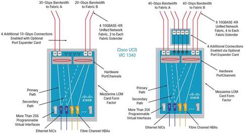
Cisco UCS VIC1340 Converged Network Adapter
The Cisco UCS Virtual Interface Card (VIC) 1340 (Figure 7) is a 2-port 40-Gbps Ethernet or dual 4 x 10-Gbps Ethernet, Fibre Channel over Ethernet (FCoE)-capable modular LAN on motherboard (mLOM) designed exclusively for the M4 generation of Cisco UCS B-Series Blade Servers. When used in combination with an optional port expander, the Cisco UCS VIC 1340 capabilities is enabled for two ports of 40-Gbps Ethernet.
The Cisco UCS VIC 1340 enables a policy-based, stateless, agile server infrastructure that can present over 256 PCIe standards-compliant interfaces to the host that can be dynamically configured as either network interface cards (NICs) or host bus adapters (HBAs). In addition, the Cisco UCS VIC 1340 supports Cisco® Data Center Virtual Machine Fabric Extender (VM-FEX) technology, which extends the Cisco UCS fabric interconnect ports to virtual machines, simplifying server virtualization deployment and management.

Figure 8 illustrates the Cisco UCS VIC 1340 Virtual Interface Cards Deployed in the Cisco UCS B-Series B200 M4 Blade Servers.
Figure 8 Cisco UCS VIC 1340 Deployed in the Cisco UCS B200 M4
Cisco Switching
Cisco Nexus 9372PX Switches
The Cisco Nexus 9372PX/9372PX-E Switches have 48 1/10-Gbps Small Form Pluggable Plus (SFP+) ports and 6 Quad SFP+ (QSFP+) uplink ports. All the ports are line rate, delivering 1.44 Tbps of throughput in a 1-rack-unit (1RU) form factor. Cisco Nexus 9372PX benefits are listed below.
Architectural Flexibility
· Includes top-of-rack or middle-of-row fiber-based server access connectivity for traditional and leaf-spine architectures
· Leaf node support for Cisco ACI architecture is provided in the roadmap
· Increase scale and simplify management through Cisco Nexus 2000 Fabric Extender support
Feature Rich
· Enhanced Cisco NX-OS Software is designed for performance, resiliency, scalability, manageability, and programmability
· ACI-ready infrastructure helps users take advantage of automated policy-based systems management
· Virtual Extensible LAN (VXLAN) routing provides network services
· Cisco Nexus 9372PX-E supports IP-based endpoint group (EPG) classification in ACI mode
Highly Available and Efficient Design
· High-density, non-blocking architecture
· Easily deployed into either a hot-aisle and cold-aisle configuration
· Redundant, hot-swappable power supplies and fan trays
Simplified Operations
· Power-On Auto Provisioning (POAP) support allows for simplified software upgrades and configuration file installation
· An intelligent API offers switch management through remote procedure calls (RPCs, JSON, or XML) over a HTTP/HTTPS infrastructure
· Python Scripting for programmatic access to the switch command-line interface (CLI)
· Hot and cold patching, and online diagnostics
Investment Protection
A Cisco 40 Gb bidirectional transceiver allows reuse of an existing 10 Gigabit Ethernet multimode cabling plant for 40 Gigabit Ethernet Support for 1 Gb and 10 Gb access connectivity for data centers migrating access switching infrastructure to faster speed. The following is supported:
· 1.44 Tbps of bandwidth in a 1 RU form factor
· 48 fixed 1/10-Gbps SFP+ ports
· 6 fixed 40-Gbps QSFP+ for uplink connectivity that can be turned into 10 Gb ports through a QSFP to SFP or SFP+ Adapter (QSA)
· Latency of 1 to 2 microseconds
· Front-to-back or back-to-front airflow configurations
· 1+1 redundant hot-swappable 80 Plus Platinum-certified power supplies
· Hot swappable 2+1 redundant fan tray
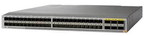
Figure 9 Nexus 9372PX Switch
Cisco Nexus 1000V Distributed Virtual Switch
Get highly secure, multitenant services by adding virtualization intelligence to your data center network with the Cisco Nexus 1000V Switch for VMware vSphere. This switch does the following:
· Extends the network edge to the hypervisor and virtual machines
· Is built to scale for cloud networks
· Forms the foundation of virtual network overlays for the Cisco Open Network Environment and Software Defined Networking (SDN)
Important Differentiators for the Cisco Nexus 1000V for VMware vSphere
The following lists the benefits of the Cisco Nexus 1000V for VMware vSphere:
· Extensive virtual network services built on Cisco advanced service insertion and routing technology
· Support for vCloud Director and vSphere hypervisor
· Feature and management consistency for easy integration with the physical infrastructure
· Exceptional policy and control features for comprehensive networking functionality
· Policy management and control by the networking team instead of the server virtualization team (separation of duties)
Virtual Networking Services
The Cisco Nexus 1000V Switch optimizes the use of Layer 4 - 7 virtual networking services in virtual machine and cloud environments through Cisco vPath architecture services.
Cisco vPath 2.0 supports service chaining so you can use multiple virtual network services as part of a single traffic flow. For example, you can simply specify the network policy, and vPath 2.0 can direct traffic through the Cisco Virtual Security Gateway for Nexus 1000V Switch for a zoning firewall.
Additionally, Cisco vPath works on VXLAN to support movement between servers in different Layer 2 domains. Together, these features promote highly secure policy, application, and service delivery in the cloud.
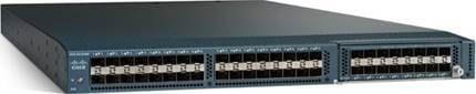
Cisco MDS 9148S Fiber Channel Switch
The Cisco MDS 9148S 16G Multilayer Fabric Switch is the next generation of the highly reliable Cisco MDS 9100 Series Switches. It includes up to 48 auto-sensing line-rate 16-Gbps Fibre Channel ports in a compact easy to deploy and manage 1-rack-unit (1RU) form factor. In all, the Cisco MDS 9148S is a powerful and flexible switch that delivers high performance and comprehensive Enterprise-class features at an affordable price.
MDS 9148S has a pay-as-you-grow model which helps you scale from a 12 port base license to a 48 port with an incremental 12-port license. This helps customers to pay and activate only the required ports.
MDS 9148S has a dual power supply and FAN trays to provide physical redundancy. The software features, like ISSU and ISSD, helps with upgrading and downgrading code with-out reloading the switch and without interrupting the live traffic.
Features and Capabilities
Benefits
· Flexibility for growth and virtualization
· Easy deployment and management
· Optimized bandwidth utilization and reduced downtime
· Enterprise-class features and reliability at low cost
Features
· PowerOn Auto Provisioning and intelligent diagnostics
· In-Service Software Upgrade and dual redundant hot-swappable power supplies for high availability
· Role-based authentication, authorization, and accounting services to support regulatory requirements
· High-performance interswitch links with multipath load balancing
· Smart zoning and virtual output queuing
· Hardware-based slow port detection and recovery
Specifications at-a-Glance
Performance and Port Configuration
· 2/4/8/16-Gbps auto-sensing with 16 Gbps of dedicated bandwidth per port
· Up to 256 buffer credits per group of 4 ports (64 per port default, 253 maximum for a single port in the group)
· Supports configurations of 12, 24, 36, or 48 active ports, with pay-as-you-grow, on-demand licensing
Advanced Functions
· Virtual SAN (VSAN)
· Inter-VSAN Routing (IVR)
· PortChannel with multipath load balancing
· Flow-based and zone-based QoS
Hypervisor and Desktop Broker
This Cisco Validated Design includes VMware vSphere 6 and VMware Horizon 7.0.3.
VMware vSphere 6.0
VMware provides virtualization software. VMware’s enterprise software hypervisors for servers VMware vSphere ESX, vSphere ESXi, and VSphere—are bare-metal hypervisors that run directly on server hardware without requiring an additional underlying operating system. VMware vCenter Server for vSphere provides central management and complete control and visibility into clusters, hosts, virtual machines, storage, networking, and other critical elements of your virtual infrastructure.
VMware vSphere 6.0 introduces many enhancements to vSphere Hypervisor, VMware virtual machines, vCenter Server, virtual storage, and virtual networking, further extending the core capabilities of the vSphere platform.
VMware ESXi 6.0 Hypervisor
vSphere 6.0 introduces a number of new features in the hypervisor:
· Scalability Improvements
ESXi 6.0 dramatically increases the scalability of the platform. With vSphere Hypervisor 6.0, clusters can scale to as many as 64 hosts, up from 32 in previous releases. With 64 hosts in a cluster, vSphere 6.0 can support 8000 virtual machines in a single cluster. This capability enables greater consolidation ratios, more efficient use of VMware vSphere Distributed Resource Scheduler (DRS), and fewer clusters that must be separately managed. Each vSphere Hypervisor 6.0 instance can support up to 480 logical CPUs, 12 terabytes (TB) of RAM, and 1024 virtual machines. By using the newest hardware advances, ESXi 6.0 enables the virtualization of applications that previously had been thought to be non-virtualizable.
Security Enhancements
· ESXi 6.0 offers these security enhancements:
- Account management: ESXi 6.0 enables management of local accounts on the ESXi server using new ESXi CLI commands. The capability to add, list, remove, and modify accounts across all hosts in a cluster can be centrally managed using a vCenter Server system. Previously, the account and permission management functions for ESXi hosts were available only for direct host connections. The setup, removal, and listing of local permissions on ESXi servers can also be centrally managed.
- Account lockout: ESXi Host Advanced System Settings have two new options for the management of failed local account login attempts and account lockout duration. These parameters affect Secure Shell (SSH) and vSphere Web Services connections, but not ESXi direct console user interface (DCUI) or console shell access.
- Password complexity rules: In previous versions of ESXi, password complexity changes had to be made by manually editing the /etc/pam.d/passwd file on each ESXi host. In vSphere 6.0, an entry in Host Advanced System Settings enables changes to be centrally managed for all hosts in a cluster.
- Improved auditability of ESXi administrator actions: Prior to vSphere 6.0, actions at the vCenter Server level by a named user appeared in ESXi logs with the vpxuser username: for example, [user=vpxuser]. In vSphere 6.0, all actions at the vCenter Server level for an ESXi server appear in the ESXi logs with the vCenter Server username: for example, [user=vpxuser: DOMAIN\User]. This approach provides a better audit trail for actions run on a vCenter Server instance that conducted corresponding tasks on the ESXi hosts.
- Flexible lockdown modes: Prior to vSphere 6.0, only one lockdown mode was available. Feedback from customers indicated that this lockdown mode was inflexible in some use cases. With vSphere 6.0, two lockdown modes are available:
o In normal lockdown mode, DCUI access is not stopped, and users on the DCUI access list can access the DCUI.
o In strict lockdown mode, the DCUI is stopped.
o Exception users: vSphere 6.0 offers a new function called exception users. Exception users are local accounts or Microsoft Active Directory accounts with permissions defined locally on the host to which these users have host access. These exception users are not recommended for general user accounts, but they are recommended for use by third-party applications—for service accounts, for example—that need host access when either normal or strict lockdown mode is enabled. Permissions on these accounts should be set to the bare minimum required for the application to perform its task and with an account that needs only read-only permissions on the ESXi host.
- Smart card authentication to DCUI: This function is for U.S. federal customers only. It enables DCUI login access using a Common Access Card (CAC) and Personal Identity Verification (PIV). The ESXi host must be part of an Active Directory domain.
VMware Horizon Version 7
Enterprise IT organizations are tasked with the challenge of provisioning Microsoft Windows apps and desktops while managing cost, centralizing control, and enforcing corporate security policy. Deploying Windows apps to users in any location, regardless of the device type and available network bandwidth, enables a mobile workforce that can improve productivity. With VMware Horizon 7, IT can effectively control app and desktop provisioning while securing data assets and lowering capital and operating expenses.
VMware Horizon
VMware Horizon desktop virtualization solutions built on a unified architecture so they are simple to manage and flexible enough to meet the needs of all your organization's users. You use the same architecture and management tools to manage public, private, and hybrid cloud deployments as you do for on premises deployments
· VMware Horizon Virtual machines and RDSH known as server-based hosted sessions: These are applications hosted from Microsoft Windows servers to any type of device, including Windows PCs, Macs, smartphones, and tablets. Some VMware editions include technologies that further optimize the experience of using Windows applications on a mobile device by automatically translating native mobile-device display, navigation, and controls to Windows applications; enhancing performance over mobile networks; and enabling developers to optimize any custom Windows application for any mobile environment.
· VMware Horizon RDSH session users also known as server-hosted desktops: These are inexpensive, locked-down Windows virtual desktops hosted from Windows server operating systems. They are well suited for users, such as call center employees, who perform a standard set of tasks.
Advantages of Using VMware Horizon
VMware Horizon 7 provides the following new features and enhancements:
· Instant Clones
- A new type of desktop virtual machines that can be provisioned significantly faster than the traditional Composer linked clones.
- A fully functional desktop can be provisioned in two seconds or less.
- Recreating a desktop pool with a new OS image can be accomplished in a fraction of the time it takes a Composer desktop pool because the parent image can be prepared well ahead of the scheduled time of pool recreation.
- Clones are automatically rebalanced across available datastores.
- View storage accelerator is automatically enabled.
· VMware Blast Extreme
- VMware Blast Extreme is now fully supported on the Horizon platform.
- Administrators can select the VMware Blast display protocol as the default or available protocol for pools, farms, and entitlements.
- End users can select the VMware Blast display protocol when connecting to remote desktops and applications.
- VMware Blast Extreme features include:
o TCP and UDP transport support
o H.264 support for the best performance across more devices
o Reduced device power consumption for longer battery life
o NVIDIA GRID acceleration for more graphical workloads per server, better performance, and a superior remote user experience
· True SSO
- For VMware Identity Manager integration, True SSO streamlines the end-to-end login experience. After users log in to VMware Identity Manager using a smart card or an RSA SecurID or RADIUS token, users are not required to also enter Active Directory credentials in order to use a remote desktop or application.
- Uses a short-lived Horizon virtual certificate to enable a password-free Windows login.
- Supports using either a native Horizon Client or HTML Access.
- System health status for True SSO appears in the Horizon Administrator dashboard.
- Can be used in a single domain, in a single forest with multiple domains, and in a multiple-forest, multiple-domain setup.
· Smart Policies
- Control of the clipboard cut-and-paste, client drive redirection, USB redirection, and virtual printing desktop features through defined policies.
- PCoIP session control through PCoIP profiles.
- Conditional policies based on user location, desktop tagging, pool name, and Horizon Client registry values.
· Configure the clipboard memory size for VMware Blast and PCoIP sessions
Horizon administrators can configure the server clipboard memory size by setting GPOs for VMware Blast and PCoIP sessions. Horizon Client 4.1 users on Windows, Linux, and Mac OS X systems can configure the client clipboard memory size. The effective memory size is the lesser of the server and client clipboard memory size values.
· VMware Blast network recovery enhancements
Network recovery is now supported for VMware Blast sessions initiated from iOS, Android, Mac OS X, Linux, and Chrome OS clients. Previously, network recovery was supported only for Windows client sessions. If you lose your network connection unexpectedly during a VMware Blast session, Horizon Client attempts to reconnect to the network and you can continue to use your remote desktop or application. The network recovery feature also supports IP roaming, which means you can resume your VMware Blast session after switching to a WiFi network.
· Configure Horizon Administrator to not remember the login name
Horizon administrators can configure not to display the Remember user name check box and therefore not remember the administrator's login name.
· Allow Mac OS X users to save credentials
Horizon administrators can configure Connection Server to allow Horizon Client Mac OS X systems to remember a user's user name, password, and domain information. If users choose to have their credentials saved, the credentials are added to the login fields in Horizon Client on subsequent connections.
· Microsoft Windows 10
- Windows 10 is supported as a desktop guest operating system
- Horizon Client runs on Windows 10
- Smart card is supported on Windows 10
- The Horizon User Profile Migration tool migrates Windows 7, 8/8.1, Server 2008 R2, or Server 2012 R2 user profiles to Windows 10 user profiles.
· RDS Desktops and Hosted Apps
- View Composer. View Composer and linked clones provide automated and efficient management of RDS server farms.
- Graphics Support. Existing 3D vDGA and GRID vGPU graphics solutions on VDI desktops have been extended to RDS hosts, enabling graphics-intensive applications to run on RDS desktops and Hosted Apps.
- Enhanced Load Balancing. A new capability provides load balancing of server farm applications based on memory and CPU resources.
- One-Way AD Trusts. One-way AD trust domains are now supported. This feature enables environments with limited trust relationships between domains without requiring Horizon Connection Server to be in an external domain.
· Cloud Pod Architecture (CPA) Enhancements
- Hosted App Support. Support for application remoting allows applications to be launched using global entitlements across a pod federation.
- HTML Access (Blast) Support. Users can use HTML Access to connect to remote desktops and applications in a Cloud Pod Architecture deployment.
· Access Point Integration
- Access Point is a hardened Linux-based virtual appliance that protects virtual desktop and application resources to allow secure remote access from the Internet. Access Point provides a new authenticating DMZ gateway to Horizon Connection Server. Smart card support on Access Point is available as a Tech Preview. Security server will continue to be available as an alternative configuration. For more information, see Deploying and Configuring Access Point.
· FIPS
- Install-time FIPS mode allows customers with high security requirements to deploy Horizon 6.
· Graphics Enhancements
- AMD vDGA enables vDGA pass-through graphics for AMD graphics hardware.
- 4K resolution monitors (3840x2160) are supported.
· Horizon Administrator Enhancements
- Horizon Administrator shows additional licensing information, including license key, named user and concurrent connection user count.
- Pool creation is streamlined by letting Horizon administrators to clone existing pools.
· Horizon 6 for Linux Desktop Enhancements
- Several new features are supported on Horizon 6 for Linux desktops, including NVIDIA GRID vGPU, vSGA, RHEL 7.2 and Ubuntu 16.04 guest operating systems, and View Agent installation of JRE 8 with no user steps required.
- Support for managed virtual machines
- Support for smart card redirection with SSO
- Support for Horizon Client for iOS
- Support for SLES 12 SP1
- Support for H.264 encoder software
- Support for IPv6 with VMware Blast Extreme on security servers.
- Horizon Administrator security protection layer. See VMware Knowledge Base (KB) article 2144303 for more information:
- Protection against inadvertent pool deletion.
- RDS per-device licensing improvements.
- Support for Intel vDGA.
- Support for AMD Multiuser GPU Using vDGA.
- More resilient upgrades.
- Display scaling for Windows Horizon Clients.
- DPI scaling is supported if it is set at the system level and the scaling level is greater than 100.
What are VMware RDS Hosted Sessions?
The following describes the VMware RDS Hosted Sessions:
· An RDS host is a server computer that hosts applications and desktop sessions for remote access. An RDS host can be a virtual machine or a physical server.
· An RDS host has the Microsoft Remote Desktop Services role, the Microsoft Remote Desktop Session Host service, and Horizon Agent installed. Remote Desktop Services was previously known as Terminal Services. The Remote Desktop Session Host service allows a server to host applications and remote desktop sessions. With Horizon Agent installed on an RDS host, users can connect to applications and desktop sessions by using the display protocol PCoIP or Blast Extreme. Both protocols provide an optimized user experience for the delivery of remote content, including images, audio and video.
· The performance of an RDS host depends on many factors. For information on how to tune the performance of different versions of Windows Server, see http://msdn.microsoft.com/library/windows/hardware/gg463392.aspx.
· Horizon 7 supports at most one desktop session and one application session per user on an RDS host.
· When users submit print jobs concurrently from RDS desktops or applications that are hosted on the same RDS host, the ThinPrint server on the RDS host processes the print requests serially rather than in parallel. This can cause a delay for some users. Note that the print server does not wait for a print job to complete before processing the next one. Print jobs that are sent to different printers will print in parallel.
· If a user launches an application and also an RDS desktop, and both are hosted on the same RDS host, they share the same user profile. If the user launches an application from the desktop, conflicts may result if both applications try to access or modify the same parts of the user profile, and one of the applications may fail to run properly.
· The process of setting up applications or RDS desktops for remote access involves the following tasks:
· Installing Applications
- If you plan to create application pools, you must install the applications on the RDS hosts. If you want Horizon 7 to automatically display the list of installed applications, you must install the applications so that they are available to all users from the Start menu. You can install an application at any time before you create the application pool. If you plan to manually specify an application, you can install the application at any time, either before or after creating an application pool.
· Important
- When you install an application, you must install it on all the RDS hosts in a farm and in the same location on each RDS host. If you do not, a health warning will appear on the View Administrator dashboard. In such a situation, if you create an application pool, users might encounter an error when they try to run the application.
- When you create an application pool, Horizon 7 automatically displays the applications that are available to all users rather than individual users from the Start menu on all of the RDS hosts in a farm. You can choose any applications from that list. In addition, you can manually specify an application that is not available to all users from the Start menu. There is no limit on the number of applications that you can install on an RDS host.
Farms, RDS Hosts, and Desktop and Application Pools
With VMware Horizon, you can create desktop and application pools to give users remote access to virtual machine-based desktops, session-based desktops, physical computers, and applications. Horizon takes advantage of Microsoft Remote Desktop Services (RDS) and VMware PC-over-IP (PCoIP) technologies to provide high-quality remote access to users.
· RDS Hosts
- RDS hosts are server computers that have Windows Remote Desktop Services and View Agent installed. These servers host applications and desktop sessions that users can access remotely. To use RDS desktop pools or applications, your end users must have access to Horizon Client 3.0 or later software.
· Desktop Pools
- There are three types of desktop pools: automated, manual, and RDS. Automated desktop pools use a vCenter Server virtual machine template or snapshot to create a pool of identical virtual machines. Manual desktop pools are a collection of existing vCenter Server virtual machines, physical computers, or third-party virtual machines. In automated or manual pools, each machine is available for one user to access remotely at a time. RDS desktop pools are not a collection of machines, but instead, provide users with desktop sessions on RDS hosts. Multiple users can have desktop sessions on an RDS host simultaneously.
· Application Pools
- Application pools let you deliver applications to many users. The applications in application pools run on a farm of RDS hosts.
· Farms
- Farms are collections of RDS hosts and facilitate the management of those hosts. Farms can have a variable number of RDS hosts and provide a common set of applications or RDS desktops to users. When you create an RDS desktop pool or an application pool, you must specify a farm. The RDS hosts in the farm provide desktop and application sessions to users.
Some of the latest VMware Horizon features and enhancements are:
· Flash Redirection
You can compile a black list to ensure that the URLs specified in the list will not be able to redirect Flash content. You must enable the GPO setting FlashMMRUrlListEnableType to use either a white list or black list.
· Horizon Agent Policy Settings
- The VMwareAgentCIT policy setting enables remote connections to Internet Explorer to use the Client's IP address instead of the IP address of the remote desktop machine.
- The FlashMMRUrlListEnableType and FlashMMRUrlList policy settings specify and control the white list or black list that enables or disables the list of URLs from using Flash Redirection.
· Horizon PowerCLI
- View PowerCLI is deprecated. Horizon PowerCLI replaces View PowerCLI and includes cmdlets that you can use with VMware PowerCLI.
- For more information about Horizon PowerCLI cmdlets, read the VMware PowerCLI Cmdlets Reference.
- For information on the API specifications to create advanced functions and scripts to use with Horizon PowerCLI, see the API Reference at the VMware Developer Center
- For more information on sample scripts that you can use to create your own Horizon PowerCLI scripts, see the Horizon PowerCLI community on GitHub.
· Horizon 7 for Linux desktops enhancements
- Audio input support
- Ubuntu 16.04 support
- Software H.264 Encoder to support multiple monitors
- Clipboard redirection support on all distributions
- vGPU support with NVIDIA M6 graphics card on RHEL 6.6/6.7/6.8/7.2 Workstation x64
· Horizon Agent and Horizon Client can now leverage H.264 codec technology. Previously, Horizon Agent and Horizon Client supported only a single monitor. This feature has been enhanced to support multiple monitors.
· Remote Desktop Operating System
The following remote desktop operating systems are now supported:
- Windows 10 version 1607 Long-Term Servicing Branch (LTSB)
- Windows Server 2016
· Composer
For enhanced security, you can enable the digest access authentication method for Composer.
· Persona Management
- Persona Management supports guest operating systems that use the "v6" version of the user profile.
- You can use the migration tool to migrate the "v2" and "v5" user profiles versions to the "v6" user profile version. The tool is installed with the Persona binary file.
Supported Windows 10 Operating Systems
Horizon 7 version 7.0.3 supports the following Windows 10 operating systems:
· Windows 10 version 1507 (RTM) Long-Term Servicing Branch (LTSB)
· Windows 10 version 1511 Current Business Branch (CBB)
· Windows 10 version 1607 Long-Term Servicing Branch (LTSB)
· Windows 10 version 1607 Current Branch (CB) as a tech preview feature
![]() Windows 10 LTSB version 1607 being used in this study
Windows 10 LTSB version 1607 being used in this study
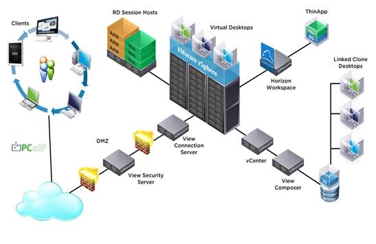
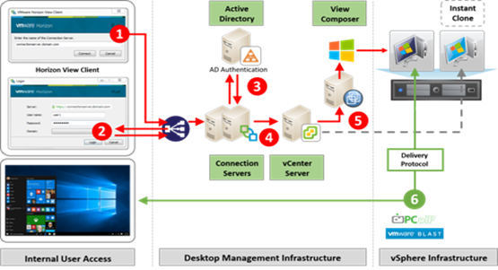
Figure 10 Logical Architecture of VMware Horizon
VMware Horizon Composer
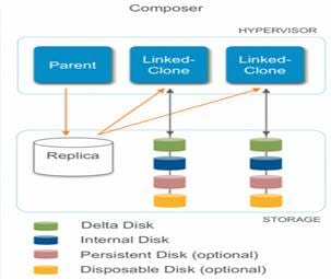
VMware Horizon Composer is a feature in Horizon that gives administrators the ability to manage virtual machine pools or the desktop pools that share a common virtual disk. An administrator can update the master image, then all desktops using linked clones of that master image can also be patched. Updating the master image will patch the cloned desktops of the users without touching their applications, data or settings.
The VMware View Composer pooled desktops solution’s infrastructure is based on software-streaming technology. After installing and configuring the composed pooled desktops, a single shared disk image (Master Image) is taken a snapshot of the OS and application image, and then storing that snapshot file accessible to host(s).
Figure 11 VMware Horizon Composer
Desktop Virtualization Design Fundamentals
An ever growing and diverse base of user devices, complexity in management of traditional desktops, security, and even Bring Your Own (BYO) device to work programs are prime reasons for moving to a virtual desktop solution.
VMware Horizon Design Fundamentals
VMware Horizon 7 integrates Remote Desktop Server Hosted sessions users and VDI desktop virtualization technologies into a unified architecture that enables a scalable, simple, efficient, mixed users and manageable solution for delivering Windows applications and desktops as a service.
Users can select applications from an easy-to-use “store” that is accessible from tablets, smartphones, PCs, Macs, and thin clients. VMware Horizon delivers a native touch-optimized experience via PCoIP or Blast Extreme high-definition performance, even over mobile networks.
Horizon VDI Pool and RDSH Servers Pool
Collections of identical Virtual Machines (VMs) or physical computers are managed as a single entity called a Desktop Pool. In this CVD, VM provisioning relies on VMware View Composer aligning with VMware Horizon Connection Server with vCenter Server components. In this CVD, machines in the Pools are configured to run either a Windows Server 2012 OS (for RDS Hosted shared sessions) and a Windows 10 Desktop OS (for pooled VDI desktops)
Figure 12 VMware Horizon Design Overview
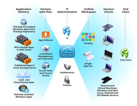
Figure 13 Horizon VDI and RDSH Desktop Delivery Based on Display Protocol (PCoIP/Blast/RDP)
IBM FlashSystem A9000 Storage
IBM FlashSystem A9000 and FlashSystem A9000R bring together the world-class ease of use from Spectrum Accelerate software and the microsecond response times that are provided by IBM FlashCore technology.
The unique module design and logical topology of IBM FlashSystem A9000 fundamentally differentiate them from traditional, monolithic systems. This architectural divergence extends to the exceptional reliability, availability, and serviceability (RAS) aspects of the system.
FlashSystem A9000 consists of three grid controllers and one flash enclosure. Each component is a 2U unit, for a total of 8U of required rack space. FlashSystem A9000 must be installed by an IBM SSR, and it can be placed into a customer-provided standard 19-inch rack. Communication between the grid controllers and the flash enclosure is over InfiniBand. All cabling between the grid controllers and the flash enclosure is fully redundant by using two sets of cables. The cables use industry standard plugs.
Each module (the flash enclosure and the three grid controllers) requires two independent power sources. For the detailed requirements that apply to your country, see IBM FlashSystem A9000 Models 9836-415 and 9838-415 Deployment Guide, GC27-8564.
IBM FlashSystem Grid Controller
The grid controller acts as a core component, providing the interface and compute functions. It also provides cache to accelerate both read and write operations. Furthermore, the grid controller is responsible for the inline data reduction through data deduplication and compression. Data compression is assisted by hardware accelerator cards.
The grid controller is based on dual Intel Xeon processors. It offers two CPU sockets, 24 dynamic device reconfiguration 4 (DDR4) error correction code (ECC)-capable memory slots, and high-speed Peripheral Component Interconnect Express (PCIe) 3.0 connectors to attach and serve all I/O ports that are required for FlashSystem A9000 and FlashSystem A9000R. The CPU sockets support Intel Xeon E5-26xx v3 series processors.
IBM FlashSystem Flash Enclosure
The flash enclosure components include the flash modules (the MicroLatency modules), battery modules, power supplies, and two fully redundant canisters.
Each flash enclosure canister contains the following components:
· RAID controller
· Two interface modules
· Management module
· Two hot-swappable fan modules
· Two Ethernet ports
· Two USB ports
The two interface controllers are at the top of the container and feature two 40 Gbps InfiniBand ports. The two 1 Gbps Ethernet ports are at the left and right edges of the canister.
Spectrum Accelerate Feature Set
FlashSystem A9000 incorporates autonomic and proactive monitoring and self-healing features. These features enable preventative measures to preserve data redundancy before a component malfunction occurs. The system is automatically restored to full redundancy within minutes of a hardware failure. When a grid controller fails, its workload is directly taken over by another grid controller.
FlashSystem A9000 and FlashSystem A9000R provide an all-inclusive software license. All features, including replication, migration, encryption, and data reduction, are included at no additional charge and apply to the entire storage system:
· Data reduction: pattern removal, data deduplication, and compression. FlashSystem A9000 and FlashSystem A9000R use industry-leading data reduction technology that combines inline, real-time pattern matching and removal, data deduplication, and compression. Compression also uses hardware cards inside each grid controller. Compression can easily provide a 2:1 data reduction saving rate on its own, effectively doubling the system storage capacity. Combined with pattern removal and data deduplication services, FlashSystem A9000 and FlashSystem A9000R can easily yield an effective data capacity of five times the original usable physical capacity. Data deduplication applies to data blocks of 8 KB or larger. Data reduction is implemented below the global cache to ensure rapid response times, provide a global scope for data reduction services, and allow other data services to be unaffected, including snapshots, replication, and host offload features, such as the VMware vStorage application programming interface (API) for Array Integration (VAAI).
· Multi-tenancy. FlashSystem A9000 and FlashSystem A9000R enable the secure isolation of logical domains of storage resources among numerous tenants, with the ability to set different quality of service (QoS) levels for each domain. Multi-tenancy enables the division of storage system administration tasks into logical domains, by using role-based permissions. It also enables rapid deployments while it minimizes the need for extensive planning, tuning, or field upgrades.
· Host rate limiting: quality of service (QoS). FlashSystem A9000 and FlashSystem A9000R system resources, such as storage and cache, constitute a virtualized environment that is shared by all hosts and applications. This approach lends itself well to accommodate high-performance requirements for multiple applications with similar performance objectives through fair resource allocation. QoS is available at the domain, pool, and volume level. In environments with applications with various performance objectives, the QoS feature enables the client to restrict input/output operations per second (IOPS), bandwidth, or both to the correct domain, pool, host group, or volume. QoS can be used to ensure that applications do not use too much of the storage system resources. Therefore, QoS maximizes the resources that are available for applications that require the best performance.
· Fibre Channel (FC) and internet Small Computer System Interface (iSCSI). FlashSystem A9000 and FlashSystem A9000R both support the Fibre Channel and iSCSI communications protocols for host attachment and remote mirroring.
· Snapshots. The snapshot capabilities use a redirect on write design that allows snapshots to occur in a sub-second time frame with no performance impact. The system supports multiple differential snapshots of a volume. Any of the snapshots can be made writable. Then, snapshots can be taken of the newly writable snapshots (snapshots of snapshots). Volumes can even be restored from these writable snapshots.
· Synchronous and asynchronous remote mirroring to another FlashSystem A9000 or FlashSystem A9000R. Synchronous or asynchronous remote mirroring can be performed over Fibre Channel (FC) or Internet Protocol (IP) iSCSI connections. Both protocols are also supported for two-way mirroring connectivity. Synchronous remote mirroring is used when a zero recovery point objective (RPO) is required. For practical reasons (latency), ensure that the distance is shorter than 100 km (62 miles). For longer distances, asynchronous replication is more appropriate.
· Data migration. FlashSystem A9000 or FlashSystem A9000R can act as a host, gaining access to volumes on an existing storage system. The system is configured as a proxy to respond to requests between the current hosts and the storage while all existing data is migrated in the background.
· Hyper-Scale Mobility. IBM Hyper-Scale Mobility allows a volume to be migrated non-disruptively from one FlashSystem A9000 to another over synchronous wide area network (WAN) distances without any host disruption. This capability is in addition to the standard data migration that allows a FlashSystem A9000 system to be a proxy as a host and to migrate volumes from other third-party arrays. For more information about replication and migration, see the IBM Redbooks publication, IBM FlashSystem A9000 and A9000R Replication Solutions, REDP-5401.
· Encryption. FlashSystem A9000 or FlashSystem A9000R helps secure data with industry-standard Advanced Encryption Standard (AES)-256 encryption for data at rest. Encryption is accomplished in hardware to avoid any performance impact. External key management, IBM Security Key Lifecycle Manager (SKLM) for example, is required. For more information, see the IBM Redbooks publication, Data-at-rest Encryption for IBM FlashSystem A9000, IBM FlashSystem A9000R and XIV Storage System, REDP-5402.
· Authentication by using Lightweight Directory Access Protocol (LDAP). LDAP can be used to provide user logon authentication, allowing FlashSystem A9000 or FlashSystem A9000R to integrate with Microsoft Active Directory, Open LDAP, or Oracle Java Systems Directory Server. Multiple directory servers can be configured to provide redundancy if one server becomes unavailable. See the IBM Redbooks publication, Using IBM FlashSystem A9000 and IBM FlashSystem A9000R with Active Directory, REDP-5387.
· OpenStack and REST support. FlashSystem A9000 or FlashSystem A9000R can use the well-established IBM code base for OpenStack and Representational State Transfer (REST) API support.
· VMware synergy. IBM Spectrum Control™ Base V3.1 allows a simplified deployment and efficient integration of FlashSystem A9000 and FlashSystem A9000R with the VMware vCloud suite.
What is Versastack?
VersaStack CI (Converged Infrastructure) is a flexible, all-flash converged infrastructure solution that brings the flash revolution to your data center, faster. It combines the latest in compute, network, storage hardware and virtualization software, into a single, integrated architecture that speeds time to deployment, lowers overall IT costs and reduces deployment risk. Highly efficient components reduce the costs associated with power, cooling and data center space. Based on 100 percent flash storage, VersaStack CI provides the performance and reliability business-critical applications demand.
The hardware foundation of VersaStack CI includes IBM FlashSystem storage arrays, Cisco UCS Blade Servers, Cisco Nexus ethernet switches and Cisco MDS fibre channel switches. VMware vSphere provides the virtualization technology.
Figure 14 VersaStack Converged Infrastructure (CI)
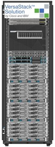
VersaStack CI is available from qualified VersaStack Partners who help to provide an excellent converged infrastructure ownership experience. VersaStack Partners have the knowledge and experience necessary to help streamline the sizing, procurement, and delivery of your entire system.
Both the hardware and software components are combined into a single integrated unit that helps in faster deployments and lowers overall IT costs.
Why VersaStack?
The following lists the benefits of VersaStack:
· Consistent Performance and Scalability
- Consistent sub-millisecond latency with 100% flash storage
- Consolidate 100’s of enterprise-class applications in a single rack
- Scales easily, without disruption
- Continuous growth through multiple VersaStack CI deployments
· Operational Simplicity
- Fully tested, validated, and documented for rapid deployment
- Reduced management complexity
- Auto-aligned 512B architecture removes storage alignment issues
- No storage tuning or tiers necessary
· Lowest TCO
- Dramatic savings in power, cooling, and space with 100 percent Flash
- Industry leading data reduction
· Enterprise Grade Resiliency
- Highly available architecture with no single point of failure
- Non-disruptive operations with no downtime
- Upgrade and expand without downtime or performance loss
- Native data protection: snapshots and replication
· Suitable for even large resource-intensive workloads such as real-time analytics or heavy transactional databases
Benefits of IBM FlashSystem A9000 Series
IBM FlashSystem A9000 integrates the extreme performance of IBM FlashCore® technology, highly parallel architecture, and comprehensive data reduction into one powerful solution enabled for the cloud.
Whether you are a service provider requiring highly efficient management, or an enterprise moving to the cloud, IBM FlashSystem A9000 provides stable, reliable, and efficient storage.
Discover why IBM FlashSystem A9000 is an all-flash grid storage breakthrough that can empower your business to derive more value from your data assets.
· Microsecond response times powered by IBM FlashCore technology. Delivers microsecond response times to accelerate critical applications and achieve competitive advantages.
· Efficient storage economics with comprehensive data reduction, including flash-optimized pattern removal, deduplication and compression.
· Simplified storage administration with IBM Hyper-Scale Manager designed to streamline management of FlashSystem A9000, FlashSystem A9000R, XIV, and Spectrum Accelerate systems.
· Easy integration with almost any existing infrastructure, including those based on VMware, OpenStack, and Microsoft solutions.
· Consistent performance for mixed workloads thanks to a highly parallel grid architecture.
· Multi-tenancy and quality of service capabilities to support multi-tenant deployments and avoid "noisy neighbors."
· Comprehensive integrated storage services based on field-proven IBM Spectrum Accelerate software, which includes snapshots, replication and more.
· Utilizes pattern removal; inline, global deduplication; inline compression; thin provisioning; and space-efficient snapshots.
· Optimizes storage economics.
· Helps reduce both acquisition costs and total cost of ownership.
· Enables more granular data protection without increased cost.
· Cloud-optimized quality-of-service (QoS) features and multi-tenancy support.
· Enables simplified yet full-featured cloud deployments with QoS and multi-tenancy features.
· Addresses common cloud services management challenges such as “noisy neighbors” and highly variable workloads.
· Delivers microsecond response times to accelerate critical applications and achieve competitive advantages.
· Secure reliability and availability with greater than 99.999% availability, data-at-rest encryption, and 2D RAID, including patented IBM Variable Stripe RAID.
· Versatile integration capabilities
- Integrates easily with almost any existing infrastructure, including those based on VMware, OpenStack, Linux and Microsoft solutions
- Enables hypervisor and virtual environment integration
- Leverages a tight integration with IBM Spectrum Accelerate
· High reliability and availability
- Delivers greater than 99.999 percent availability
- Enables simplified disaster recovery with high availability and industry-leading data protection
· Exceptionally simple management tools
· Simplifies administration with a highly intuitive management interface
· Ease management with IBM Hyper-Scale technology
· Ability to grow and manage storage from a single interface with IBM Hyper-Scale technology
- Enables almost unlimited growth with single-pane-of-glass management
- Allows flexible, incremental capital investments
- IBM Variable Stripe RAID technology
- Maintains performance while enhancing reliability without sacrificing usable capacity
· Harness the performance of a highly parallel architecture and IBM® FlashCoreTM technology in one innovative system
· Efficient storage economics with comprehensive data reduction, including flash-optimized pattern removal, deduplication and compression
· Prevent “noisy neighbor” problems with quality-of-service (QoS) features that support multi-tenancy and mixed workloads
· Deliver consistent, extreme performance to meet service level agreements for unpredictable, data-intensive workloads
· Comprehensive integrated storage services based on field-proven IBM Spectrum Accelerate software, which includes snapshots, replication and more
· Secure reliability & availability with greater than 99.999% availability, data-at-rest encryption, and 2D RAID, including patented IBM Variable Stripe RAID
· IBM FlashSystem Supports offers:
- Performance. IBM MicroLatency performance.
- Endurance. Flash memory will be covered for read/write endurance while you are under warranty or maintenance.
- 7 year 24x7 Support. Up to 7 years of support available, with additional options like flash media retention.
- Data Reduction. FlashSystem A9000 provides inline pattern removal, deduplication and compression to make the most of your space.
- Peace of Mind. IBM provide you with complimentary lab services to help get you up and running quickly. (NEW perpetual licensing with IBM Spectrum Accelerate / IBM Spectrum Storage Suite.)
There are many reasons to consider a virtual desktop solution such as an ever growing and diverse base of user devices, complexity in management of traditional desktops, security, and even Bring Your Own Device (BYOD) to work programs. The first step in designing a virtual desktop solution is to understand the user community and the type of tasks that are required to successfully execute their role. The following user classifications are provided:
· Knowledge Workers today do not just work in their offices all day – they attend meetings, visit branch offices, work from home, and even coffee shops. These anywhere workers expect access to all of their same applications and data wherever they are.
· External Contractors are increasingly part of your everyday business. They need access to certain portions of your applications and data, yet administrators still have little control over the devices they use and the locations they work from. Consequently, IT is stuck making trade-offs on the cost of providing these workers a device vs. the security risk of allowing them access from their own devices.
· Task Workers perform a set of well-defined tasks. These workers access a small set of applications and have limited requirements from their PCs. However, since these workers are interacting with your customers, partners, and employees, they have access to your most critical data.
· Mobile Workers need access to their virtual desktop from everywhere, regardless of their ability to connect to a network. In addition, these workers expect the ability to personalize their PCs, by installing their own applications and storing their own data, such as photos and music, on these devices.
· Shared Workstation users are often found in state-of-the-art university and business computer labs, conference rooms or training centers. Shared workstation environments have the constant requirement to re-provision desktops with the latest operating systems and applications as the needs of the organization change, tops the list.
After the user classifications have been identified and the business requirements for each user classification have been defined, it becomes essential to evaluate the types of virtual desktops that are needed based on user requirements. There are essentially five potential desktops environments for each user:
· Traditional PC: A traditional PC is what typically constitutes a desktop environment: physical device with a locally installed operating system.
· Hosted Shared Desktop: A hosted, server-based desktop is a desktop where the user interacts through a delivery protocol. With hosted, server-based desktops, a single installed instance of a server operating system, such as Microsoft Windows Server 2012, is shared by multiple users simultaneously. Each user receives a desktop "session" and works in an isolated memory space. Remoted Desktop Server Hosted Server sessions: A hosted virtual desktop is a virtual desktop running on a virtualization layer (ESX). The user does not work with and sit in front of the desktop, but instead the user interacts through a delivery protocol.
· Published Applications: Published applications run entirely on the VMware Horizon RDS hosted server virtual machines and the user interacts through a delivery protocol. With published applications, a single installed instance of an application, such as Microsoft Office, is shared by multiple users simultaneously. Each user receives an application "session" and works in an isolated memory space.
· Streamed Applications: Streamed desktops and applications run entirely on the user‘s local client device and are sent from a server on demand. The user interacts with the application or desktop directly but the resources may only available while they are connected to the network.
· Local Virtual Desktop: A local virtual desktop is a desktop running entirely on the user‘s local device and continues to operate when disconnected from the network. In this case, the user’s local device is used as a type 1 hypervisor and is synced with the data center when the device is connected to the network.
Understanding Applications and Data
When the desktop user groups and sub-groups have been identified, the next task is to catalog group application and data requirements. This can be one of the most time-consuming processes in the VDI planning exercise, but is essential for the VDI project’s success. If the applications and data are not identified and co-located, performance will be negatively affected.
The process of analyzing the variety of application and data pairs for an organization will likely be complicated by the inclusion cloud applications, for example, SalesForce.com. This application and data analysis is beyond the scope of this Cisco Validated Design, but should not be omitted from the planning process. There are a variety of third party tools available to assist organizations with this crucial exercise.
Project Planning and Solution Sizing Sample Questions
Now that user groups, their applications and their data requirements are understood, some key project and solution sizing questions may be considered.
General project questions should be addressed at the outset, including:
· Has a VDI pilot plan been created based on the business analysis of the desktop groups, applications and data?
· Is there infrastructure and budget in place to run the pilot program?
· Are the required skill sets to execute the VDI project available? Can we hire or contract for them?
· Do we have end user experience performance metrics identified for each desktop sub-group?
· How will we measure success or failure?
· What is the future implication of success or failure?
Below is a short, non-exhaustive list of sizing questions that should be addressed for each user sub-group:
· What is the desktop OS planned? Windows 8 or Windows 10?
· 32 bit or 64 bit desktop OS?
· How many virtual desktops will be deployed in the pilot? In production? All Windows 8/10?
· How much memory per target desktop group desktop?
· Are there any rich media, Flash, or graphics-intensive workloads?
· Will VMware Horizon RDSH be used for Hosted Shared Server applications planned? Are they are any applications installed?
· What is the desktop OS planned for RDS Server Roles? Windows server 2008 or Server 2012?
· Will VMware Horizon Composer or another method be used for virtual desktop deployment?
· What is the hypervisor for the solution?
· What is the storage configuration in the existing environment?
· Are there sufficient IOPS available for the write-intensive VDI workload?
· Will there be storage dedicated and tuned for VDI service?
· Is there a voice component to the desktop?
· Is anti-virus a part of the image?
· Is user profile management (for example, non-roaming profile based) part of the solution?
· What is the fault tolerance, failover, disaster recovery plan?
· Are there additional desktop sub-group specific questions?
Hypervisor Selection
VMware vSphere has been identified the hypervisor for both RDS Hosted Sessions and VDI based desktops:
· VMware vSphere: VMware vSphere comprises the management infrastructure or virtual center server software and the hypervisor software that virtualizes the hardware resources on the servers. It offers features like Distributed Resource Scheduler, vMotion, high availability, Storage vMotion, VMFS, and a multi-pathing storage layer. More information on vSphere can be obtained at the VMware web site: http://www.vmware.com/products/datacentervirtualization/vsphere/overview.html.
![]() For this CVD, the hypervisor used was VMware ESXi 6.0 Update 2.
For this CVD, the hypervisor used was VMware ESXi 6.0 Update 2.
Designing a VMware Horizon Environment for a Mixed Workload
With VMware Horizon 7 the method you choose to provide applications or desktops to users depends on the types of applications and desktops you are hosting and available system resources, as well as the types of users and user experience you want to provide.
Table 1 Designing a VMware Horizon Environment
| Server OS machines |
You want: Inexpensive server-based delivery to minimize the cost of delivering applications to a large number of users, while providing a secure, high-definition user experience. Your users: Perform well-defined tasks and do not require personalization or offline access to applications. Users may include task workers such as call center operators and retail workers, or users that share workstations. Application types: Any application. |
| Desktop OS machines
|
You want: A client-based application delivery solution that is secure, provides centralized management, and supports a large number of users per host server (or hypervisor), while providing users with applications that display seamlessly in high-definition. Your users: Are internal, external contractors, third-party collaborators, and other provisional team members. Users do not require off-line access to hosted applications. Application types: Applications that might not work well with other applications or might interact with the operating system, such as .NET framework. These types of applications are ideal for hosting on virtual machines. Applications running on older operating systems such as Windows XP or Windows Vista, and older architectures, such as 32-bit or 16-bit. By isolating each application on its own virtual machine, if one machine fails, it does not impact other users. |
| Remote PC Access
|
You want: Employees with secure remote access to a physical computer without using a VPN. For example, the user may be accessing their physical desktop PC from home or through a public WIFI hotspot. Depending upon the location, you may want to restrict the ability to print or copy and paste outside of the desktop. This method enables BYO device support without migrating desktop images into the datacenter. Your users: Employees or contractors that have the option to work from home, but need access to specific software or data on their corporate desktops to perform their jobs remotely. Host: The same as Desktop OS machines. Application types: Applications that are delivered from an office computer and display seamlessly in high definition on the remote user's device. |
For the Cisco Validated Design described in this document, a mix of Remote Desktop Server Hosted sessions (RDSH) using RDS based Server OS and VMware Horizon pooled Linked Clone Virtual Machine Desktops using VDI based desktop OS machines were configured and tested.
The mix consisted of a combination of both use cases. The following sections discuss design decisions relative to the VMware Horizon deployment, including the CVD test environment.
Products Deployed
The architecture deployed is highly modular. While each customer’s environment might vary in its exact configuration, the reference architecture contained in this document once built, can easily be scaled as requirements and demands change. This includes scaling both up (adding additional resources within a Cisco UCS Domain) and out (adding additional Cisco UCS Domains and IBM FlashSystem A9000 storage Arrays)
The solution includes Cisco networking, Cisco UCS and IBM FlashSystem A9000 storage, which efficiently fit into a single data center rack, including the access layer network switches.
This validated design document details the deployment of 5000 users for a mixed VMware Horizon desktop workload featuring the following software:
This validated design document details the deployment of the multiple configurations extending to 5000 users for a mixed Horizon workload featuring the following software:
· VMware vSphere ESXi 6.0 Update 2 Hypervisor
· Microsoft SQL Server 2012
· Cisco Nexus 1000V primary and secondary Virtual Supervisor Module
· VMware Horizon 7 Shared Remote Desktop Server Hosted Sessions (RDSH) on IBM FlashSystem A9000 on fibre channel storage
· VMware Horizon 7 Non-Persistent Virtual Desktops (VDI) on IBM FlashSystem A9000 on fibre channel storage
· VMware Horizon 7 Connection Server and Additional Replica Servers
· VMware Horizon 7 Composer Server
· Windows 2012 R2 Server for Profile Manager
· Microsoft Windows Server 2012 R2
· Windows 10 64-bit virtual machine Operating Systems
Figure 15 details the physical hardware and cabling deployed to enable this solution.
Figure 15 Virtual Desktop Workload Architecture for the 5000 seat on VMware Horizon 7 on VersaStack
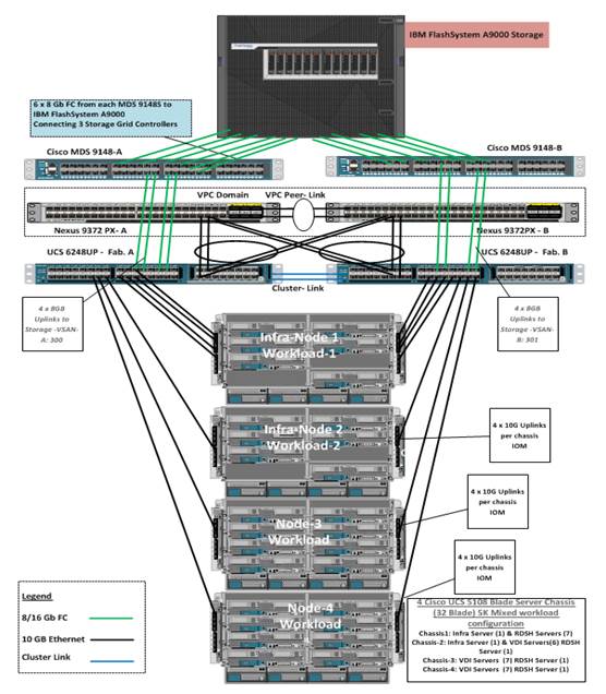
Hardware Deployed
The solution contains the following hardware as shown in Figure 15:
· Two Cisco Nexus 9372PX Layer 2 Access Switches
· Two Cisco MDS 9148S 16Gb Fibre Channel Switches
· Four Cisco UCS 5108 Blade Server Chassis with two Cisco UCS-IOM-2208XP IO Modules
· Two Cisco UCS B200 M4 Blade servers with Intel Xeon E5-2660v3 2.60-GHz 10-core processors, 128GB 2133MHz RAM, and one Cisco VIC1340 mezzanine card for the hosted infrastructure, providing N+1 server fault tolerance
· Ten Cisco UCS B200 M4 Blade servers with Intel Xeon E5-2680v4 2.40-GHz 14-core processors, 512GB 2400MHz RAM, and one Cisco VIC1340 mezzanine card for the VMware Horizon Remote Desktop Server Hosted Sessions workload, providing N+1 server fault tolerance at the workload cluster level
· Twenty Cisco UCS B200 M4 Blade servers with Intel Xeon E5-2680v4 2.40-GHz 14-core processors, 512GB 2400MHz RAM, and one Cisco VIC1340 mezzanine card for the non-persistent VMware Horizon pooled virtual desktop workload, providing N+1 server fault tolerance at the workload cluster level
· IBM FlashSystem A9000 storage with three grid controllers and an storage enclosure with 12TB usable physical capacity and 60 TB effective capacity (effect capacity assumes a data reduction that is calculated at about 5:1)
Table 2 lists the software and firmware version used in the study.
Table 2 Software and Firmware Versions used
| Vendor |
Product / Component |
Version / Build / Code |
| Cisco |
UCS Component Firmware |
3.1(2b) bundle release |
| Cisco |
UCS Manager |
3.1(2b) bundle release |
| Cisco |
UCS B200 M4 Blades |
3.1(2b) bundle release |
| Cisco |
VIC 1340 |
4.1(1d) |
| Cisco |
Nexus 1000V |
5.2.1 |
| Cisco |
Virtual Switch Update Manager |
1.56 |
| VMware |
VMware Horizon |
7.0.3 |
| VMware |
VMware Composer Server |
7.0.3 |
| VMware |
vCenter Server Appliance |
6.0.0.20000 |
| VMware |
vSphere ESXi 6.0 Update 2 |
6.0.0.4192238 |
| Storage |
IBM FlashSystem A9000 |
12.0.2.c |
Logical Architecture
The logical architecture of this solution is designed to support up to 5000 users within four Cisco UCS 5108 Blade server chassis containing 32 blades, which provides physical redundancy for the blade servers for each workload type.
Figure 16 outlines the logical architecture of the test environment, including the Login VSI session launcher self-contained end user experience benchmarking platform
Figure 16 Logical Architecture Overview
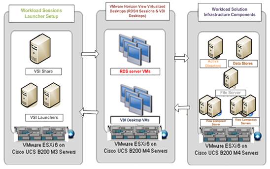
![]() This document is intended to allow you to fully configure your environment. In this process, various steps require you to insert customer-specific naming conventions, IP addresses, and VLAN schemes, as well as to record appropriate MAC addresses.
This document is intended to allow you to fully configure your environment. In this process, various steps require you to insert customer-specific naming conventions, IP addresses, and VLAN schemes, as well as to record appropriate MAC addresses.
Figure 17 identifies the server roles in the 32 server deployment to support the 5000 seat workload. We also break out the infrastructure virtual machine fault tolerant design.
Figure 17 Server, Location, and Purpose
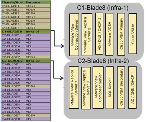
The following table outlines the virtual machine deployments on the hardware platform.
Table 3 Virtual Machine Deployment Architecture
| Server Name |
Location |
Purpose |
||
| C1-Blade 8 C2-Blade 8 |
Physical – Chassis 1, 2 |
ESXi 6.0 Hosts Infrastructure VMs Windows 2012-R2, VCenter Server Appliance, VMware Connection Servers, Replica Servers, Composer Server, Domain Controllers, SQL Server, Cisco N1KV VSM, VSUM. |
|
|
| C1-Blade1-7 C2-Blade 7 C3-Blade 7 C4-Blade 7 |
Physical – Chassis 1,2,3 & 4 |
ESXi 6.0 Hosts 81x VMware Horizon RDSH Server VMs |
|
|
| C2-Blade1-6 C3-Blade1-6 & 8 C4-Blade1-6 & 8 |
Physical – Chassis 2,3 & 4 |
ESXi 6.0 Hosts 2900x VMware Horizon VDI (Non-Persistent) VMs |
|
|
|
|
|
|
||
VLANs
The VLAN configuration recommended for the environment includes a total of seven VLANs as outlined in Table 4.
Table 4 VLANs Configured in this Study
| VLAN Name |
VLAN ID |
VLAN Purpose |
|
| Default |
1 |
Native VLAN |
|
| In-Band-Mgmt |
60 |
VLAN for in-band management interfaces |
|
| Infra-Mgmt |
61 |
VLAN for Virtual Infrastructure |
|
| VDI |
102 |
VLAN for VDI Traffic |
|
| vMotion |
66 |
VLAN for VMware vMotion |
|
| OB-Mgmt |
164 |
VLAN for out-of-band management |
|
VSANs
We utilized two virtual SANs for communications and fault tolerance in this design.
Table 5 VASNs Configured in this Study
| VSAN Name |
VSAN Purpose |
ID Used in Validating this Document |
| VSAN 1 |
VSAN for primary SAN communication |
300 |
| VSAN 2 |
VSAN for secondary SAN communication |
301 |
VMware Clusters
The following four VMware Clusters were used in one vCenter data center to support the solution and testing environment:
· VDI Cluster: IBM FlashSystem A9000 storage with Cisco UCS
- Infrastructure Cluster: Infra VMs (vCenter Appliance, Active Directory (2), DNS, DHCP, SQL Server, VMware Horizon Connection Servers, VMware Horizon Replica Servers, VMware Horizon Composer Server, Nexus 1000v Virtual Supervisor Modules ( VSMs, etc.), Microsoft SQL Server.
- RDSH: VMware Horizon RDSH (Remote Desktop Server Hosted) VMs (Windows Server 2012 R2 RDS Roles) provisioned with VMware View Composer.
- VDI Non-Persistent: VMware Horizon VDI VMs (Windows 10 64-bit non-persistent virtual desktops provisioned with VMware Horizon Composer.
· VSI Launchers Cluster
- Launcher Cluster: Login VSI Cluster (The Login VSI launcher infrastructure was connected using the same set of switches and vCenter instance, but was hosted on separate local storage and servers)
Figure 18 VMware vSphere Clusters on vSphere Web GUI
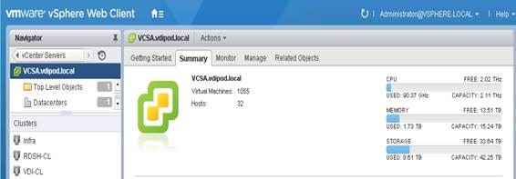
Solution Configuration
This section details the configuration and tuning that was performed on the individual components to produce a complete, validated solution. Figure 19 illustrates the configuration topology for this solution.
Configuration Topology for Scalable VMware Horizon Mixed Workload
Component Layers
Figure 19 Solution Component Layers
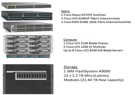
Figure 19 above captures the architectural diagram for the purpose of this study. The architecture is divided into three distinct layers:
· Cisco UCS Compute Platform
· Network Access layer and LAN
· Storage Access to the IBM FlashSystem A9000 Storage Array
Solution Cabling
The following sections detail the physical connectivity configuration of the VersaStack 5000 seat VMware Horizon 7 environment.
The information in this section is provided as a reference for cabling the physical equipment in this Cisco Validated Design environment. To simplify cabling requirements, the tables include both local and remote device and port locations.
The tables in this section contain the details for the prescribed and supported configuration of the IBM FlashSystem A9000 to the Cisco 6248UP Fabric Interconnects via Cisco MDS 9148S FC switches.
![]() This document assumes that out-of-band management ports are plugged into an existing management infrastructure at the deployment site. These interfaces will be used in various configuration steps.
This document assumes that out-of-band management ports are plugged into an existing management infrastructure at the deployment site. These interfaces will be used in various configuration steps.
![]() Be sure to follow the cabling directions in this section. Failure to do so will result in necessary changes to the deployment procedures that follow because specific port locations are mentioned.
Be sure to follow the cabling directions in this section. Failure to do so will result in necessary changes to the deployment procedures that follow because specific port locations are mentioned.
Figure 20 shows a cabling diagram for a VMware Horizon configuration using the Cisco Nexus 9000, Cisco MDS 9100 Series and IBM FlashSystem A9000 storage Array. The IBM FlashSystem should be connected according to best practices for the IBM flash enclosure and grid controllers.
Figure 20 VersaStack 5000 Seat Cabling Diagram
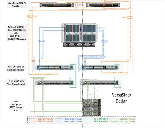
Cisco Nexus Switch Cabling Details
Table 6 Cisco Nexus 9372-A Cabling Information
| Local Device |
Local Port |
Connection |
Remote Device |
Remote Port |
| `
|
Eth1/17 |
10GbE |
Cisco UCS fabric interconnect A |
Eth1/17 |
| Eth1/18 |
10GbE |
Cisco UCS fabric interconnect A |
Eth1/18 |
|
| Eth1/19 |
10GbE |
Cisco UCS fabric interconnect B |
Eth1/17 |
|
| Eth1/20 |
10GbE |
Cisco UCS fabric interconnect B |
Eth1/18 |
|
| Eth1/49 |
40GbE |
Cisco Nexus 9372 B |
Eth1/49 |
|
| Eth1/50 |
40GbE |
Cisco Nexus 9372 B |
Eth1/50 |
|
|
|
MGMT0 |
GbE |
GbE management switch |
Any |
![]() For devices requiring GbE connectivity, use the GbE Copper SFP+s (GLC-T=).
For devices requiring GbE connectivity, use the GbE Copper SFP+s (GLC-T=).
Table 7 Cisco Nexus 9372-B Cabling Information
| Local Device |
Local Port |
Connection |
Remote Device |
Remote Port |
| Cisco Nexus 9372 B
|
Eth1/17 |
10GbE |
Cisco UCS fabric interconnect A |
Eth1/19 |
| Eth1/18 |
10GbE |
Cisco UCS fabric interconnect A |
Eth1/20 |
|
| Eth1/19 |
10GbE |
Cisco UCS fabric interconnect B |
Eth1/19 |
|
| Eth1/20 |
10GbE |
Cisco UCS fabric interconnect B |
Eth1/20 |
|
| Eth1/49 |
40GbE |
Cisco Nexus 9372 A |
Eth1/49 |
|
| Eth1/50 |
40GbE |
Cisco Nexus 9372 A |
Eth1/50 |
|
|
|
MGMT0 |
GbE |
GbE management switch |
Any |
Cisco UCS 6248UP Fabric Interconnect Cabling
Table 8 Cisco UCS Fabric Interconnect A Cabling Information
| Local Device |
Local Port |
Connection |
Remote Device |
Remote Port |
| Cisco UCS fabric interconnect A
|
Eth1/17 |
10GbE |
Cisco Nexus 9372 A |
Eth1/17 |
| Eth1/18 |
10GbE |
Cisco Nexus 9372 A |
Eth1/18 |
|
| Eth1/19 |
10GbE |
Cisco Nexus 9372 B |
Eth1/17 |
|
| Eth1/20 |
10 GbE |
Cisco Nexus 9372 B |
Eth 1/18 |
|
| Eth1/1-1/4 |
10GbE |
UCS 5108 Blade Chassis IOM-A, Chassis 1 |
IOM 1-4 |
|
| Eth1/5-1/8 |
10GbE |
UCS 5108 Blade Chassis IOM-A, Chassis 2 |
IOM 1-4 |
|
| Eth1/9-1/12 |
10GbE |
UCS 5108 Blade Chassis IOM-A, Chassis 3 |
IOM 1-4 |
|
| Eth 1/13-1/16 |
10GbE |
UCS 5108 Blade Chassis IOM-A, Chassis 4 |
IOM 1-4 |
|
| MGMT0 |
GbE |
GbE management switch |
Any |
|
| L1 |
GbE |
Cisco UCS fabric interconnect B |
L1 |
|
|
|
L2 |
GbE |
Cisco UCS fabric interconnect B |
L2 |
|
|
FC 2/13 |
8Gb FC |
Cisco MDS 9148S-A |
FC 1/37 |
|
|
FC 2/14 |
8Gb FC |
Cisco MDS 9148S-A |
FC 1/38 |
|
|
FC 2/15 |
8Gb FC |
Cisco MDS 9148S-A |
FC 1/39 |
|
|
FC 2/16 |
8Gb FC |
Cisco MDS 9148S-A |
FC 1/40 |
Table 9 Cisco UCS Fabric Interconnect B Cabling Information
| Local Device |
Local Port |
Connection |
Remote Device |
Remote Port |
| Cisco UCS fabric interconnect B
|
Eth1/17 |
10GbE |
Cisco Nexus 9372 A |
Eth1/19 |
| Eth1/18 |
10GbE |
Cisco Nexus 9372 A |
Eth1/20 |
|
| Eth1/19 |
10GbE |
Cisco Nexus 9372 B |
Eth1/19 |
|
| Eth1/20 |
10GbE |
Cisco Nexus 9372 B |
Eth1/20 |
|
| Eth1/1-1/4 |
10GbE |
UCS 5108 Blade Chassis IOM-B, Chassis 1 |
IOM 1-4 |
|
| Eth1/1-1/8 |
10GbE |
UCS 5108 Blade Chassis IOM-B, Chassis 2 |
IOM 1-4 |
|
| Eth1/9-1/12 |
10GbE |
UCS 5108 Blade Chassis IOM-B, Chassis 3 |
IOM 1-4 |
|
| Eth 1/13-1/16 |
10GbE |
UCS 5108 Blade Chassis IOM-B, Chassis 4 |
IOM 1-4 |
|
| L1 |
GbE |
Cisco UCS fabric interconnect B |
L1 |
|
|
|
L2 |
GbE |
Cisco UCS fabric interconnect B |
L2 |
|
|
FC 2/13 |
8Gb FC |
Cisco MDS 9148S-B |
FC 1/37 |
|
|
FC 2/14 |
8Gb FC |
Cisco MDS 9148S-B |
FC 1/38 |
|
|
FC 2/15 |
8Gb FC |
Cisco MDS 9148S-B |
FC 1/39 |
|
|
FC 2/16 |
8Gb FC |
Cisco MDS 9148S-B |
FC 1/40 |

Cisco MDS 9148S Cabling
Figure 21 illustrates the cable connectivity between the Cisco MDS 9148S and the Cisco 6248 Fabric Interconnects and the IBM FlashSystem A9000 Storage.
We used two 8Gb FC connections from each Fabric Interconnect to each MDS switch.
We utilized six 8Gb FC connections from the IBM FlashSystem A9000 storage to each MDS switch.
Table 10 Cisco MDS 9148S A Cabling
| Local Device |
Local Port |
Connection |
Remote Device |
Remote Port |
| Cisco MDS 9148S-A
|
fc1/37 |
8Gb FC |
Cisco 6248UP Fabric Interconnect-A |
fc2/13 |
| fc1/38 |
8Gb FC |
Cisco 6248UP Fabric Interconnect-A |
fc2/14 |
|
| fc1/39 |
8Gb FC |
Cisco 6248UP Fabric Interconnect-A |
fc2/15 |
|
| fc1/40 |
8Gb FC |
Cisco 6248UP Fabric Interconnect-A |
fc2/16 |
|
| fc1/43 |
8Gb FC |
IBM FlashSystem A9000 storage |
fc1/1 |
|
| fc1/44 |
8Gb FC |
IBM FlashSystem A9000 storage |
fc2/1 |
|
| fc1/45 |
8Gb FC |
IBM FlashSystem A9000 storage |
fc3/1 |
|
| fc1/46 |
8Gb FC |
IBM FlashSystem A9000 storage |
fc1/3 |
|
|
|
fc1/47 |
8 GB FC |
IBM FlashSystem A9000 storage |
fc2/3 |
|
|
Fc1/48 |
8 Gb FC |
IBM FlashSystem A9000 storage |
fc3/3 |
Table 11 Cisco MDS 9148S B Cabling
| Local Device |
Local Port |
Connection |
Remote Device |
Remote Port |
| Cisco MDS 9148S-B
|
fc1/37 |
8Gb FC |
Cisco 6248UP Fabric Interconnect-B |
fc2/13 |
| fc1/38 |
8Gb FC |
Cisco 6248UP Fabric Interconnect-B |
fc2/14 |
|
| fc1/39 |
8Gb FC |
Cisco 6248UP Fabric Interconnect-B |
fc2/15 |
|
| fc1/40 |
8Gb FC |
Cisco 6248UP Fabric Interconnect-B |
fc2/16 |
|
| fc1/43 |
8Gb FC |
IBM FlashSystem A9000 storage |
fc1/2 |
|
| fc1/44 |
8Gb FC |
IBM FlashSystem A9000 storage |
fc2/2 |
|
| fc1/45 |
8Gb FC |
IBM FlashSystem A9000 storage |
fc3/2 |
|
| fc1/46 |
8Gb FC |
IBM FlashSystem A9000 storage |
fc1/4 |
|
|
|
fc1/47 |
8 GB FC |
IBM FlashSystem A9000 storage |
fc2/4 |
|
|
Fc1/48 |
8 Gb FC |
IBM FlashSystem A9000 storage |
fc3/4 |
VersaStack Fabric to IBM FlashSystem A9000 FlashSystem Cabling
IBM FlashSystem A9000 grid controllers 01, 02 and 03 connection to MDS A and B Switches using VSAN 300 for Fabric A and VSAN 301 Configured for Fabric B.
Figure 22 IBM FlashSystem A9000 storage connectivity to Cisco MDS FC switches
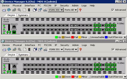
Figure 23 Fibre Channel Cable Connectivity from IBM FlashSystem A9000 to Cisco MDS 9148S to Cisco 6248 Fabric Interconnects
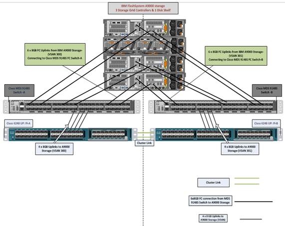
Cisco Unified Computing System Base Configuration
This section details the Cisco UCS configuration that was done as part of the infrastructure build out. The racking, power, and installation of the chassis are described in the install guide (see www.cisco.com/c/en/us/support/servers-unified-computing/ucs-manager/products-installation-guides-list.html) and it is beyond the scope of this document.
For more information about each step, refer to the following documents: Cisco UCS Manager Configuration Guides – GUI and Command Line Interface (CLI) Cisco UCS Manager - Configuration Guides - Cisco
Cisco UCS Manager Software Version 3.1(2b)
This document assumes the use of Cisco UCS Manager Software version 3.1(2b). To upgrade the Cisco UCS Manager software and the Cisco UCS 6248 Fabric Interconnect software to a higher version of the firmware,) refer to Cisco UCS Manager Install and Upgrade Guides.
Configure Fabric Interconnects at Console
To configure the fabric interconnect, complete the following steps:
1. Connect a console cable to the console port on what will become the primary fabric interconnect.
2. If the fabric interconnect was previously deployed and you want to erase it to redeploy, follow these steps:
a. Login with the existing user name and password
b. Enter: connect local-mgmt
c. Enter: erase config
d. Enter: yes to confirm
3. After the fabric interconnect restarts, the out-of-box first time installation prompt appears, type “console” and press Enter.
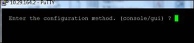
4. Type “setup” at the setup/restore prompt, then press Enter.

5. Type “y” then press Enter to confirm the setup.
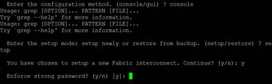
6. Type “y” or “n” depending on your organization’s security policies, then press Enter.
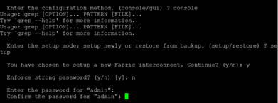
7. Enter and confirm the password and enter switch Fabric A.
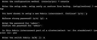
8. Complete the setup dialog questions.
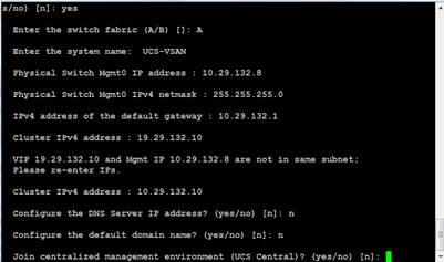
9. Review the selections and type “yes”.
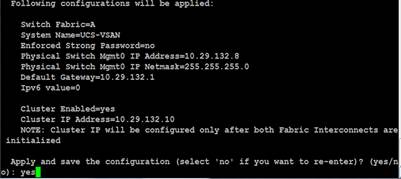
10. Console onto second fabric interconnect, select console as the configuration method and provide the following inputs.
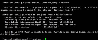
11. Open a web browser and go to the Virtual IP address configured above.
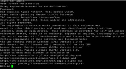
Base Cisco UCS System Configuration
To configure the Cisco Unified Computing System, complete the following steps:
1. Open a web browser and navigate to the Cisco UCS 6248 Fabric Interconnect cluster address.
2. Click the Launch UCS Manager link to download the Cisco UCS Manager software.
3. If prompted to accept security certificates, accept as necessary.
4. When prompted, enter admin as the user name and enter the administrative password.
5. To log in to Cisco UCS Manager, click Login.
Set Fabric Interconnects to Fibre Channel End Host Mode
To set the Fabric Interconnects to the Fibre Channel End Host Mode, complete the following steps:
1. On the Equipment tab, expand the Fabric Interconnects node and click Fabric Interconnect A.
2. On the General tab in the Actions pane, click Set FC End Host mode.
3. Follow the dialogs to complete the change.

![]() Both Fabric Interconnects automatically reboot sequentially when you confirm you want to operate in this mode.
Both Fabric Interconnects automatically reboot sequentially when you confirm you want to operate in this mode.
Configure Fibre Channel Uplink Ports
To configure the Fibre Channel Uplink Ports, complete the following steps:
1. After the restarts are complete, from the General tab, Actions pane, click Configure Unified ports.
2. Click Yes to confirm in the pop-up window.
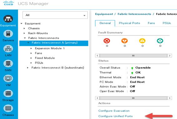
3. Click Configure Expansion Module Ports.

4. Move the slider to the left.
Ports to the right of the slider will become FC ports. For our study, we configured the last four ports on the Expansion Module as FC ports.
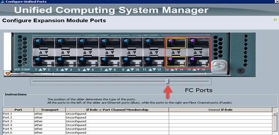
5. Click Finish, then click Yes to confirm. This action will cause a reboot of the Expansion Module.
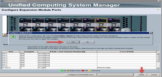
After the expansion module reboot, your FC Ports configuration should look like the screenshot below:
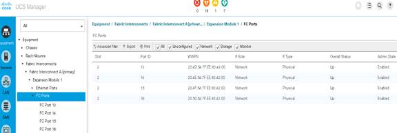
6. Repeat this procedure for Fabric Interconnect B.
7. Insert Cisco SFP 8 Gbps FC (DS-SFP-FC8-SW) modules into ports 13 through 16 on both Fabric Interconnects and cable as prescribed later in this document.
Edit Chassis Discovery Policy
Setting the discovery policy simplifies the addition of B-Series Cisco UCS chassis.
To modify the chassis discovery policy, complete the following steps:
1. In Cisco UCS Manager, in the navigation pane, click the Equipment node and select Equipment in the list on the left.
2. In the right pane, click the Policies tab.
3. Under Global Policies, set the Chassis/FEX Discovery Policy to 4-link.
4. Set the Link Grouping Preference to Port Channel.
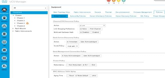
5. Click Save Changes.
6. Click OK.
Acknowledge Cisco UCS Chassis
To acknowledge all Cisco UCS chassis, complete the following steps:
1. In Cisco UCS Manager, in the navigation pane, click the Equipment tab.
2. Expand Chassis and select each chassis that is listed.
3. Right-click each chassis and select Acknowledge Chassis.
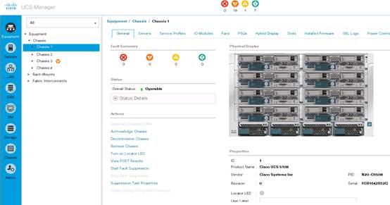
4. Click Yes and then click OK to complete acknowledging the chassis.
5. Repeat for each of the remaining chassis.
Synchronize Cisco UCS to NTP
To synchronize the Cisco UCS environment to the NTP server, complete the following steps:
1. In Cisco UCS Manager, in the navigation pane, click the Admin tab.
2. Select All > Timezone Management.
3. In the Properties pane, select the appropriate time zone in the Timezone menu.
4. Click Save Changes, and then click OK.
5. Click Add NTP Server.
6. Enter the NTP server IP address and click OK.
7. Click OK.
Enable Server and Ethernet Uplink Ports
To enable server and uplink ports, complete the following steps:
1. In Cisco UCS Manager, in the navigation pane, click the Equipment tab.
2. Select Equipment > Fabric Interconnects > Fabric Interconnect A > Fixed Module.
3. Expand Ethernet Ports.
4. Select ports 1 through 16 that are connected to the Cisco IO Modules of the four B-Series 5108 Chassis, right-click them, and select Configure as Server Port.
5. Click Yes to confirm uplink ports and click OK.
6. In the left pane, navigate to Fabric Interconnect A. In the right pane, navigate to the Physical Ports tab > Ethernet Ports tab. Confirm that ports have been configured correctly in the in the Role column.
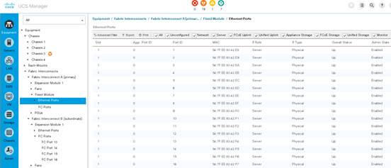
7. Repeat the above steps for Fabric Interconnect B. The screenshot below shows the server ports for Fabric B.
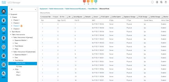
To configure network ports used to uplink the Fabric Interconnects to the Cisco Nexus 9172PX switches, complete the following steps:
1. In Cisco UCS Manager, in the navigation pane, click the Equipment tab.
2. Select Equipment > Fabric Interconnects > Fabric Interconnect A > Fixed Module.
3. Expand Ethernet Ports.
4. Select ports 1 through 4 that are connected to the Nexus 9172PX switches, right-click them, and select Configure as Network Port.
5. Click Yes to confirm ports and click OK.
6. In the left pane, navigate to Fabric Interconnect A. In the right pane, navigate to the Physical Ports tab > Ethernet Ports tab. Confirm that ports have been configured correctly in the in the Role column.
7. Verify the Ports connected to Cisco Nexus upstream switches are now configured as network ports.
8. Repeat the above steps for Fabric Interconnect B. The screenshot shows the network uplink ports for Fabric B.
9. Successful configuration should result in ports 1-4 configured as network ports as shown in the screen shot below:

Create Uplink Port Channels to Cisco Nexus 9372PX Switches
In this procedure, two port channels are created: one from Fabric A to both Cisco Nexus 9372PX switches and one from Fabric B to both Cisco Nexus 9372PX switches.
To configure the necessary port channels in the Cisco UCS environment, complete the following steps:
1. In Cisco UCS Manager, click the LAN tab in the navigation pane.
2. Under LAN > LAN Cloud, expand node Fabric A tree:
3. Right-click Port Channels.
4. Select Create Port Channel.
5. Enter 11 as the unique ID of the port channel.
6. Enter FI-A-Uplink as the name of the port channel.
7. Click Next.

8. Select ethernet ports 1-4 for the port channel
9. Click Finish.
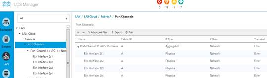
Repeat steps 1-9 for Fabric Interconnect B, substituting 12 for the port channel number and FI-B-Uplink for the name. The resulting configuration should look like the screenshot below:
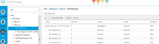
Create Uplink Port Channels to Cisco MDS 9148S Switches
In this procedure, two port channels are created: One from Fabric A to Cisco MDS 9148S switch A and one from Fabric B to Cisco MDS 9148S switch B.
To configure the necessary port channels in the Cisco UCS environment, complete the following steps:
1. In Cisco UCS Manager, click the SAN tab in the navigation pane.
2. Under SAN > SAN Cloud, right-click Fabric A Create Resource Pools
Create Required Shared Resource Pools
This section details how to create the MAC address, iSCSI IQN, iSCSI IP, UUID suffix and server pools.
Create MAC Address Pools
To configure the necessary MAC address pools for the Cisco UCS environment, complete the following steps:
1. In Cisco UCS Manager, click the LAN tab in the navigation pane.
2. Select Pools > root.
3. Right-click MAC Pools under the root organization.
4. Select Create MAC Pool to create the MAC address pool.
5. Enter MAC_Pool_A as the name for MAC pool.
6. Optional: Enter a description for the MAC pool.
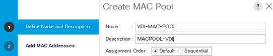
7. Enter the seed MAC address and provide the number of MAC addresses to be provisioned.
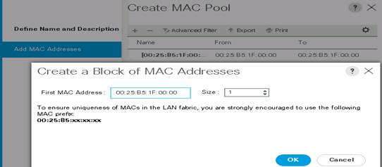
8. Click OK, then click Finish.
9. In the confirmation message, click OK.
Create KVM IP Address Pool
An IP address pool on the out of band management network must be created to facilitate KVM access to each compute node in the Cisco UCS domain.
To create the pool, complete the following steps:
1. Click the LAN tab in UCS Manager, expand the Pools node, expand the root node, right-click IP Pools, then click Create IP Pool.
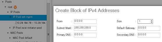
2. Provide a Name, choose Default or Sequential, and then click Next.
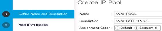
3. Click the green + sign to add an IPv4 address block.
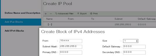
4. Complete the starting IP address, size, subnet mask, default gateway, primary and secondary DNS values for your network, then click OK.
5. Click Finish.
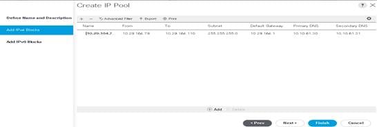
6. Click OK.
Create WWPN Pools
To configure the necessary WWPN pools for the Cisco UCS environment, complete the following steps:
1. In Cisco UCS Manager, click the SAN tab in the navigation pane.
2. Select Pools > root.
3. Under WWPN Pools, right click WWPN Pools and select Create WWPN Pool.
4. Assign a name and optional description.
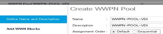
5. Assignment order can remain Default.
6. Click Next.
7. Click Add to add block of Ports.
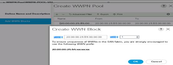
8. Enter number of WWNNs. For this study we had 80 WWNNs.
9. Click Finish.
Create UUID Suffix Pool
To configure the necessary universally unique identifier (UUID) suffix pool for the Cisco UCS environment, complete the following steps:
1. In Cisco UCS Manager, click the Servers tab in the navigation pane.
2. Select Pools > root.
3. Right-click UUID Suffix Pools.
4. Select Create UUID Suffix Pool.
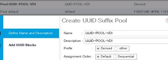
5. Enter UUID_Pool-VDI as the name of the UUID suffix pool.
6. Optional: Enter a description for the UUID suffix pool.
7. Keep the prefix at the derived option.
8. Click Next.
9. Click Add to add a block of UUIDs.
10. Create a starting point UUID seed for your environment.
11. Specify a size for the UUID block that is sufficient to support the available blade or server resources.
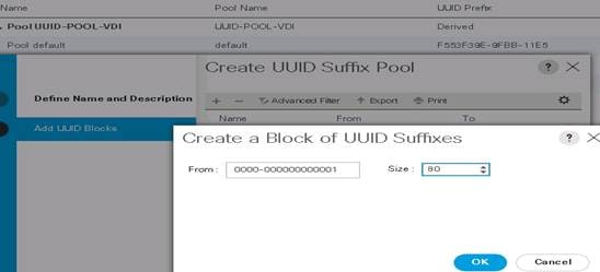
Create Server Pool
To configure the necessary server pool for the Cisco UCS environment, complete the following steps:
![]() Consider creating unique server pools to achieve the granularity that is required in your environment.
Consider creating unique server pools to achieve the granularity that is required in your environment.
1. In Cisco UCS Manager, click the Servers tab in the navigation pane.
2. Select Pools > root.
3. Right-click Server Pools.
4. Select Create Server Pool.
5. Enter Infra_Pool as the name of the server pool.
6. Optional: Enter a description for the server pool.
7. Click Next.
8. Select two (or more) servers to be used for the VMware management cluster and click >> to add them to the Infra_Pool server pool.
9. Click Finish.
10. Click OK.
11. Create additional Server Pools for Horizon Linked Clone servers and Horizon RDSH servers
Create VLANs
To configure the necessary virtual local area networks (VLANs) for the Cisco UCS environment, complete the following steps:
1. In Cisco UCS Manager, click the LAN tab in the navigation pane.
![]() In this procedure, six unique VLANs are created. Refer to Table 12.
In this procedure, six unique VLANs are created. Refer to Table 12.
| VLAN Name |
VLAN ID |
VLAN Purpose |
vNIC Assignment |
| Default |
1 |
Native VLAN |
vNIC-Template-A vNIC-Template-B |
| In-Band-Mgmt |
60 |
VLAN for in-band management interfaces |
vNIC-Template-A vNIC-Template-B |
| Infra-Mgmt |
61 |
VLAN for Virtual Infrastructure |
vNIC-Template-A vNIC-Template-B |
| vMotion |
66 |
VLAN for VMware vMotion |
vNIC-Template-A vNIC-Template-B |
| VDI |
102 |
Virtual Desktop traffic |
vNIC-Template-A vNIC-Template-B |
| OB-Mgmt |
164 |
VLAN for out-of-band management interfaces |
vNIC-Template-A vNIC-Template-B |
2. Select LAN > LAN Cloud.
3. Right-click VLANs.
4. Select Create VLANs
5. Enter MGMT as the name of the VLAN to be used for in-band management traffic.
6. Keep the Common/Global option selected for the scope of the VLAN.
7. Enter 60 as the ID of the management VLAN.
8. Keep the Sharing Type as None.
9. Click OK, and then click OK again.
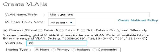
10. Repeat the above steps to create all VLANs and configure the Default VLAN as native.

Create VSANs
To configure the necessary virtual storage area networks (VSANs) for the Cisco UCS environment, complete the following steps:
1. In Cisco UCS Manager, click the SAN tab in the navigation pane.
![]() In this procedure, two VSANs are created. When these VSANs are created, be sure to add them to the port-channel uplink created earlier.
In this procedure, two VSANs are created. When these VSANs are created, be sure to add them to the port-channel uplink created earlier.
2. Select SAN > SAN Cloud.
3. Under Fabric A, right-click VSANs.
4. Select Create VSANs.
5. Enter VSAN-300 as the name of the VSAN to be used for in-band management traffic.
6. Select Fabric A for the scope of the VSAN.
7. Enter 300 as the ID of the VSAN.
8. Click OK, and then click OK again.
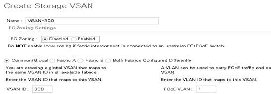
9. Repeat the above steps on Fabric B with VSAN30 to create the VSANs necessary for this solution.
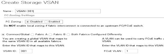
VSAN 300 and 301 are configured as shown below:
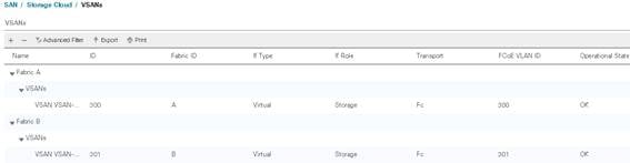
10. After configuring VSANs both sides, go into the port-channel created earlier in the section ‘Create uplinks for MDS 9148S' and add the respective VSANs to their port channels. VSAN300 in this study is assigned to Fabric A and VSAN301 is assigned to Fabric B. (VSAN300 Should only be on Fabric A and VSAN301 on Fabric B).
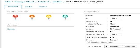
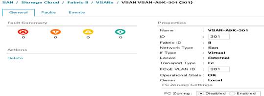
11. Go to the Port-Channel for each Fabric and assign the VSAN appropriately.
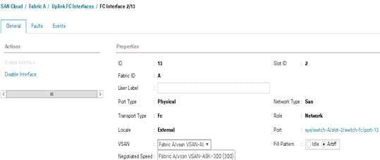
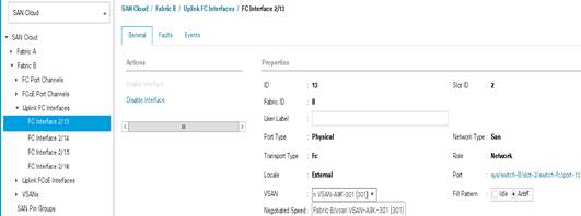
Create Host Firmware Package
Firmware management policies allow the administrator to select the corresponding packages for a given server configuration. These policies often include packages for adapter, BIOS, board controller, FC adapters, host bus adapter (HBA) option ROM, and storage controller properties.
To create a firmware management policy for a given server configuration in the Cisco UCS environment, complete the following steps:
1. In Cisco UCS Manager, click the Servers tab in the navigation pane.
2. Select Policies > root.
3. Right-click Host Firmware Packages.
4. Select Create Host Firmware Package.
5. Enter VM-Host as the name of the host firmware package.
6. Leave Simple selected.
7. Select the version 3.1(2b) for both the Blade Package
8. Click OK to create the host firmware package.
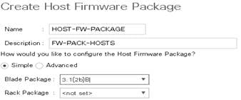
Set Jumbo Frames in Cisco UCS Fabric
To configure jumbo frames and enable quality of service in the Cisco UCS fabric, complete the following steps:
1. In Cisco UCS Manager, click the LAN tab in the navigation pane.
2. Select LAN > LAN Cloud > QoS System Class.
3. In the right pane, click the General tab.
4. On the Best Effort row, enter 9216 in the box under the MTU column.
5. Click Save Changes in the bottom of the window.
6. Click OK.
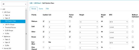
Create Network Control Policy for Cisco Discovery Protocol
To create a network control policy that enables Cisco Discovery Protocol (CDP) on virtual network ports, complete the following steps:
1. In Cisco UCS Manager, click the LAN tab in the navigation pane.
2. Select Policies > root.
3. Right-click Network Control Policies.
4. Select Create Network Control Policy.
5. Enter Enable_CDP as the policy name.
6. For CDP, select the Enabled option.
7. Click OK to create the network control policy.
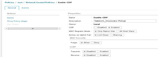
Create Power Control Policy
To create a power control policy for the Cisco UCS environment, complete the following steps:
1. In Cisco UCS Manager, click the Servers tab in the navigation pane.
2. Select Policies > root.
3. Right-click Power Control Policies.
4. Select Create Power Control Policy.
5. Enter No-Power-Cap as the power control policy name.
6. Change the power capping setting to No Cap.
7. Click OK to create the power control policy.
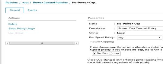
Cisco UCS System Configuration for Cisco UCS B-Series
Create Server BIOS Policy
To create a server BIOS policy for the Cisco UCS environment, complete the following steps:
1. In Cisco UCS Manager, click the Servers tab in the navigation pane.
2. Select Policies > root.
3. Right-click BIOS Policies.
4. Select Create BIOS Policy.
5. Enter B200-M4-BIOS as the BIOS policy name.
6. Configure the remaining BIOS policies as follows and click Finish.
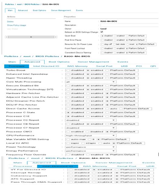
7. Click Finish.
Configure Update Default Maintenance Policy
To update the default Maintenance Policy, complete the following steps:
1. In Cisco UCS Manager, click the Servers tab in the navigation pane.
2. Select Policies > root.
3. Select Maintenance Policies > default.
4. Change the Reboot Policy to User Ack.
5. Click Save Changes.
6. Click OK to accept the change.
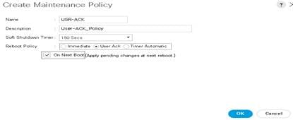
Create vNIC Templates for Cisco UCS B-Series
To create multiple virtual network interface card (vNIC) templates for the Cisco UCS environment, complete the following steps:
1. In Cisco UCS Manager, click the LAN tab in the navigation pane.
2. Select Policies > root.
3. Right-click vNIC Templates.
4. Select Create vNIC Template.
5. Enter vNIC_Template_A as the vNIC template name.
6. Keep Fabric A selected.
7. Do not select the Enable Failover checkbox.
8. Under Target, make sure that the VM checkbox is not selected.
9. Select Updating Template as the Template Type.
10. Under VLANs, select the checkboxes for MGMT, Default, Infra, VDI and vMotion.
11. Set Native-VLAN as the native VLAN.
12. For MTU, enter 9000.
13. In the MAC Pool list, select MAC_Pool_A.
14. In the Network Control Policy list, select CDP_Enabled.
15. Click OK to create the vNIC template.
16. Click OK.

17. In the navigation pane, select the LAN tab.
18. Select Policies > root.
19. Right-click vNIC Templates.
20. Select Create vNIC Template.
21. Enter vNIC_Template_B as the vNIC template name.
22. Select Fabric B.
23. Do not select the Enable Failover checkbox.
24. Under Target, make sure the VM checkbox is not selected.
25. Select Updating Template as the template type.
26. Under VLANs, select the checkboxes for MGMT, Default, VDI, Infra, and vMotion.
27. Set Native-VLAN as the native VLAN.
28. For MTU, enter 9000.
29. In the MAC Pool list, select MAC_Pool_B.
30. In the Network Control Policy list, select CDP_Enabled.
31. Click OK to create the vNIC template.
32. Click OK.
Create vHBA Templates for Cisco UCS B-Series
To create multiple virtual host bus adapter (vHBA) templates for the Cisco UCS environment, complete the following steps:
1. In Cisco UCS Manager, click the SAN tab in the navigation pane.
2. Select Policies > root.
3. Right-click vHBA Templates.
4. Select Create vHBA Template.
5. Enter vHBA-FAB-A as the vHBA template name.
6. Keep Fabric A selected.
7. Select VSAN300 for Fabric A from the drop down.
8. Change to Updating Template.
9. For Max Data Field keep 2048.
10. Select VDI-WWPN (created earlier) for our WWPN Pool.
11. Leave the remaining as is.
12. Click OK.
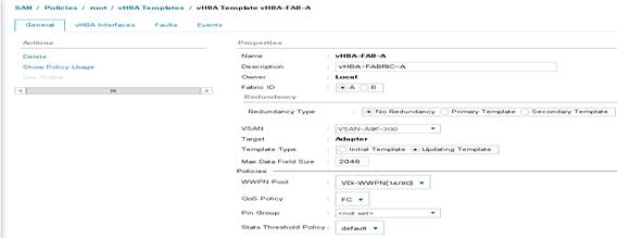
13. In the navigation pane, select the LAN tab.
14. Select Policies > root.
15. Right-click vHBA Templates.
16. Select Create vHBA Template.
17. Enter vHBA-FAB-B as the vHBA template name.
18. Select Fabric B.
19. Select VSAN301 for Fabric B from the drop down.
20. Change to Updating Template.
21. For Max Data Field keep 2048.
22. Select VDI-Pool-WWPN (created earlier) for our WWPN Pool.
23. Leave the remaining as is.
24. Click OK.
Configure Boot from SAN
All ESXi host were set to boot from SAN for the Cisco Validated Design as part of the Service Profile template. The benefits of booting from SAN are numerous; disaster recovery, lower cooling and power requirements for each server since a local drive is not required, and better performance, name just a few.
To create a boot from SAN policy, complete the following steps:
1. Go to UCS Manager, right-click the ‘Boot Policies’ option shown below and select ‘Create Boot Policy.
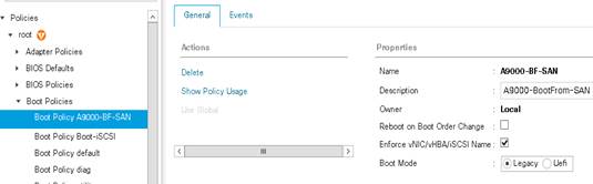
2. Name the boot policy and expand the ‘vHBAs’ menu as shown below:
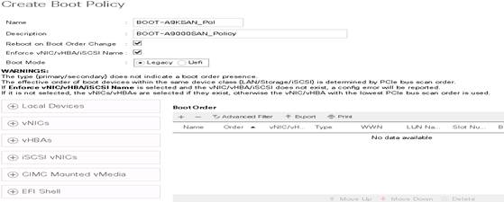

3. After selecting the ‘Add SAN Boot’ option, add the primary vHBA as shown below. Note that the vHBA name needs to match exactly. We will use the vHBA templates created in the previous step.

4. Repeat the steps to add a secondary SAN Boot option.
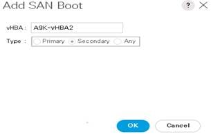
5. Add the SAN Boot Targets to the primary and secondary. The SAN boot targets will also include primary and secondary options in order to maximize resiliency and number of paths.
6. Add the SAN Boot Targets to the primary and secondary. The SAN boot targets will also include primary and secondary options in order to maximize resiliency and number of paths.
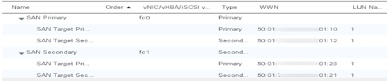
7. From the Hyper-Scale Manager GUI, find and enter the IBM FlashSystem A9000 WWN for Module01, Fibre Channel Port 1. This information can be found in the Hyper-Scale Manager GUI under System-> Actions -> Hardware -> View/Modify Ports in the right hand panel of the screen. Then select the Actions button for Port (Module 1) and select View/Edit FC Port and then at the bottom right hand side will be the WWPN:
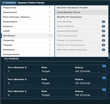
8. Select View/Edit FC Port to find WWPN.
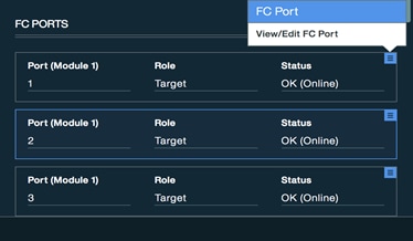
Alternatively, the WWPN can be found by using the following XCLI command, Xcli command line to get the A9000 ports list
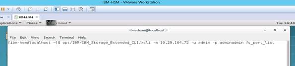
/opt/IBM/IBM_Storage_Extended_CLI/xcli -m 10.29.164.72 -u admin -p adminadmin fc_port_list
WWPN located on the bottom left of View/Edit FC Port window:
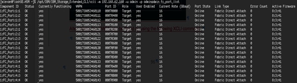
9. When the FlashSystem A9000 WWNs have been recorded, use port Module 1.FC Port 1 for the first Boot Target WWPN:
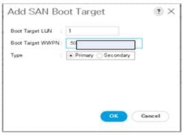
10. Add a secondary SAN Boot Target by clicking the ‘Add SAN Boot Target to SAN Primary’ while the primary SAN Boot option is highlighted. This time enter the IBM FlashSystem A9000 WWPN for Module 2.FC Port 2.
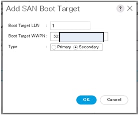
11. Repeat these steps for the secondary SAN boot target and use WWPN for Module 1 Port 2 and Module 3, Port 1 in the primary and secondary SAN boot options.
12. Below you can see a properly configured boot from SAN UCS policy. The next step is to create and attach the boot volumes to the hosts from within the Hyper-Scale Manager GUI:
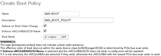
13. Provisioning a volume for SAN boot for IBM FlashSystem A9000 is simple. The only difference between a SAN volume and a vCenter datastore is that you will only connect the SAN boot volume to the single host that will be booting from the volume.
14. First a Storage Pool must be created that will be used to hold all the Volumes created for the VDI application. Storage pool form the basis for controlling the use of storage space by imposing a capacity quota on specific applications.
15. Within the IBM Hyper-Scale Manager GUI, select the +New icon from the top navigation pane and select Pool.
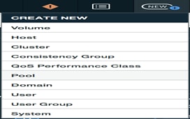
16. Enter the Name, Snapshot Reserved (GB), Pool Size (GB), System and Domain that the pool will be created in:
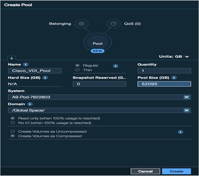
17. Within the IBM Hyper-Scale Manager GUI, select the +New icon from the top navigation pane and select Volume. Create multiple volumes since there are a large number of ESXi hosts and you need to create separate boot volumes for each one
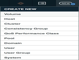
18. Enter Name, Quantity, Size, System, Domain and Pool to create the volumes.
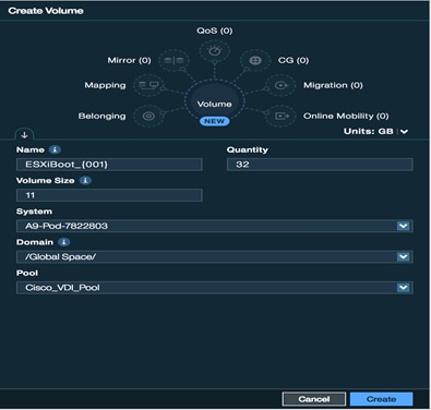
19. To connect the LUN to an ESXi host, select a newly created volume under the Volumes tab and then select ‘Mapping’ from the hub to the right and then select Add at the bottom:
The screenshot below shows that ESXi Boot LUNs have been created:
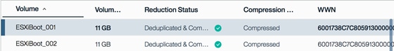
20. Select Mapping from the hub and then Add to map the volume to a host.
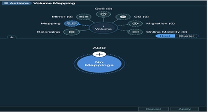
21. Click the drop-down list under host and select Add Host to create a new host entry, this will open a new tab.
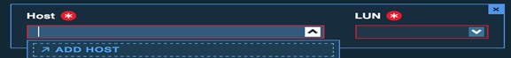
22. Enter the Name for the host and then select the + sign next to Ports to add the WWPN of the host. You can click the + sign multiple times so that you can enter all WWPN of the Host at one time Select the WWPN from the list or manually enter the WWPN. Select Create & Close to continue.

23. Click the + next to Ports and enter Port Address.
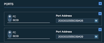
24. The Host will auto-populate in Volume Mapping. Select Apply to finish mapping Boot LUN.

Create Service Profile Templates for Cisco UCS B-Series
To create service profile templates for the Cisco UCS B-Series environment, complete the following steps:
1. Under the Servers tab in UCSM Select Service Profile Templates.
2. Right-click and select Create Service Profile Template.
3. Name the template B-Series.
4. Select the UUID pool created earlier from the dropdown in the UUID Assignment dialog.
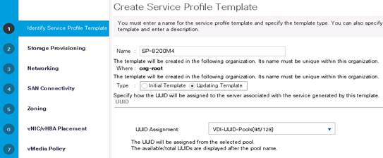
5. Click Next.
6. Click Next through Storage Provisioning.
7. Under Networking, in the “How would you like to configure LAN connectivity?” dialogue, select the Expert radio button.
8. Click Add.
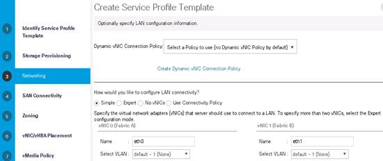
9. Name it vNIC-A.
10. Select check box for Use vNIC Template.
11. Under vNIC template select the vNIC-A.
12. For Adapter Policy select VMware.
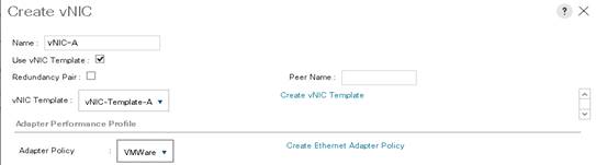
13. Repeat networking steps for vNIC-B.
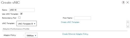
14. Click Next.
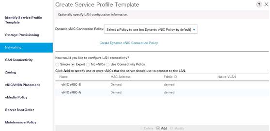
15. Click Next.
16. Under SAN Connectivity, select the Expert radio button in the “How would you like to configure SAN Connectivity?
17. Select WWNN Assignment from the Pool created earlier.
18. Click Add.
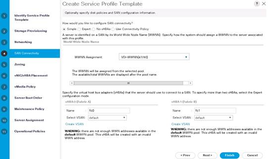
19. Name the adapter vHBA-A.
20. Click Use vHBA Template.
21. Select vHBA Template: vHBA-A.
22. Select Adapter Policy: VMWare.
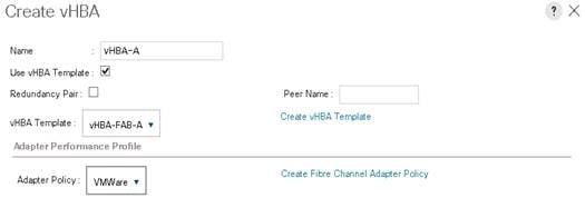
23. Repeat steps for vHBA-B on Fabric B.
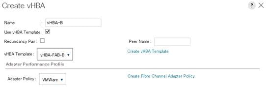
24. No Zoning will be used. Click Next.
25. Click Next through vNIC/vHBA Placement policy.
26. Click Next through vMedia Policy.
27. Use the Boot Policy drop down to select the Boot Policy created earlier, then click Finish.
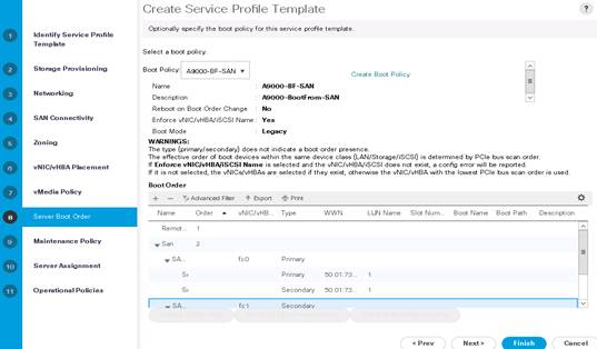
28. Select maintenance Policy and Server Assignment.
29. Click Finish and complete the Service Profile creation.
Create Service Profiles
To create service profiles for each of the blades in the VersaStack solution, complete the following steps:
1. From the Servers tab in UCS Manager, under the Service Profile Templates node, right-click the Service Profile Template created in the step above, then click Create Service Profiles from Template.
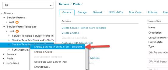
2. Provide a naming prefix, a starting number, and the number of services profiles to create, then click OK.

The requested number of service profiles (for example, 28) are created in the Service Profiles root organization.
IBM FlashSystem A9000 Configuration for Cisco Validated Design
The IBM FlashSystem A9000 contains no special configurations, tuning or value changes from the default values. For the validated design, the FlashSystem A9000 contains twelve 1.2TB MicroLatency Modules fully populated.
An IBM Support Service Representative Engineer or authorized partner will perform the installation and initial setup of the array. Setup (racking, power, cabling and array setup) is typically completed in less than one hour and will only require between 6-12 cables (that number is variable based upon number of SAN FC connections) for the system.
The Cisco UCS hosts are redundantly connected to the array controllers (via the Cisco MDS 9148S) with four FC connections to each controller from two HBAs on each Cisco UCS host over the 8/16GB Fibre Channel protocol for a total of eight logical paths for 128GB/s of total throughput with no single point of failure. The FlashSystem A9000 will support up to twelve FC connections in total in the baseline system and using all twelve connections is recommended in production deployments in order to maximize resiliency and throughput capabilities of the array.
IBM FlashSystem A9000 Configuration
The IBM FlashSystem A9000 used in this CVD, required a total of 8 rack units: 6 for the grid controllers and 2 for the array enclosure. The front view of the array can be seen in Figure 24.
Figure 24 IBM FlashSystem A9000 Storage Front View
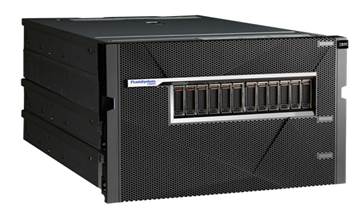
The IBM MicroLatency Modules can be accessed without removing the bezel for maintenance activities. Behind the bezel on the IBM FlashSystem A9000, the Battery Backup Units and redundant vault devices for each controller and storage enclosure can be accessed as shown in Figure 25.
Figure 25 IBM FlashSystem A9000 Storage Front View
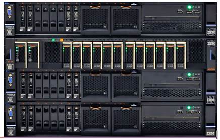
Figure 26 shows the back of the array which houses the three controllers. The rear of the array in this example includes Fibre-Channel (12x 16GB/s ports) and 10Gb iSCSI (6x 10GB/s ports) connectivity.
Figure 26 IBM FlashSystem A9000 Connectivity Overview (Back View)
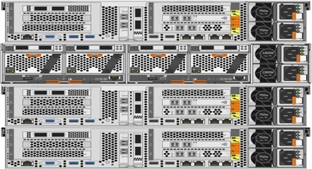
The grid controller is available in two versions that provide different I/O connectivity options. All grid controllers must be equipped with either the iSCSI-only option or the Fibre Channel with iSCSI options. When configured with Fibre Channel and iSCSi the system will include two dual port 16 Gb Fiber Channel adapters and One dual port 10 GbE adapter. When configured with the iSCSI-only option the system will include two dual port 10 GbE adapters.
Figure 27 FlashSystem A9000 configuration with FC and iSCSI Ports
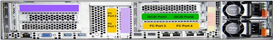
Figure 28 FlashSystem A9000 Configuration with iSCSI
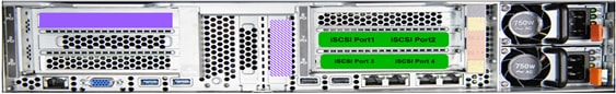
Connectivity to Cisco MDS 9148S
Figure 29 illustrates the IBM FlashSystem A9000 16GB FC connections to the redundantly paired Cisco MDS 9148S switches, yet again taking care to make certain there is no single point of path failure within the Cisco Validated Design. Not shown in this diagram are power and array/SAN management port connections.
Figure 29 IBM A9000 Connectivity to Cisco MDS 9148S FC Switches and Fabric 6248UP
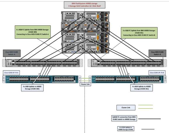
All IBM FlashSystem A9000 systems require a single IP address for management with a maximum of two. One IP address is assigned to each controller Ethernet port (eth0) on Controllers 1 and 3. Initial setup of the array and assignment of these IP addresses is accomplished by the IBM Service Support Representative during installation.
All GUI-based operations shown in this section can also be accomplished through the XCLI command line interface. For the sake of consistency, we will show all configuration steps via the GUI In addition, IBM FlashSystem A9000 features a restful API for additional extensibility and usage across a multitude of platforms and languages including PowerShell, Python and the VMware vRealize Automation Suite, among many others.
How to Install IBM Hyper-Scale Manager
The prerequisites to install IBM Hyper-Scale Manager can be found here:
https://www.ibm.com/support/knowledgecenter/STJKMM_12.0.3/hsm_ug_ch_introduction.html
Create a New Linux OS Virtual Machine
To create a new Linux OS virtual machine, complete the following steps:
1. Create a new VM to host Hyper-Scale Manager, click New Virtual Machine.
![]()
2. Click Create a new virtual machine.
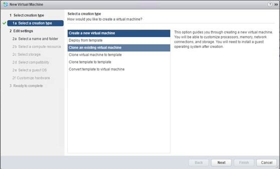
3. Enter a name for the VM.
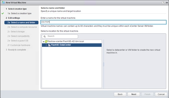
4. Select compute resource.
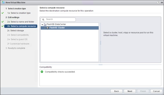
5. Select the data store to store the HSM Linux VM to be created and stored.
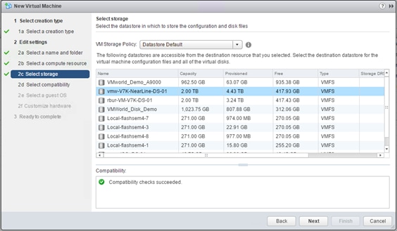
6. Select compatibility.
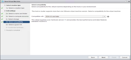
7. Select the Guest OS Family. This is Linux Based VM to be installed for IBM HSM.
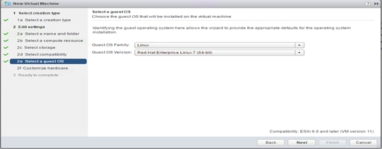
8. Create a VM with at least 2 CPU and 4 GB memory and at least 76GB free in /home.
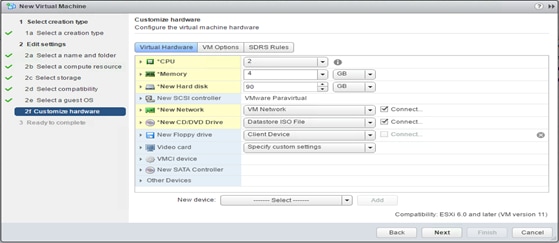
9. Review all the parameters and click Finish to complete the creation of the Linux VM for Hyper-Scale manger.
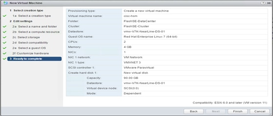
The screenshot below shows the Linux Virtual Machine being created.
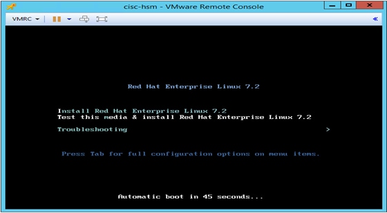
10. Select Language.

11. Configure Installation options.
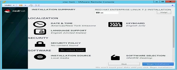
12. Configure additional installation options.
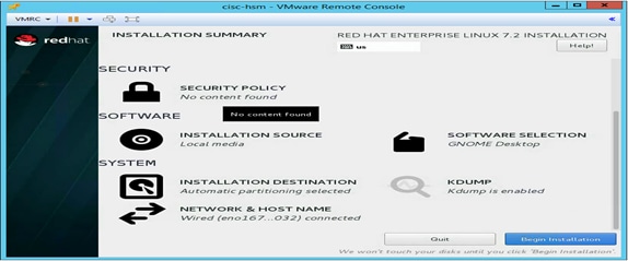
13. Set root password.
14. Reboot to complete the installation.
15. Select language.
16. Select keyboard language.
17. Select time zone.
18. Create a local user.
19. Create the local user password.

The screenshot below shows the RedHat Enterprise Linux is ready to use.
When the VM HSM Linux VM is rebooted and ready to use, install the Hyper-Scale Manager.
Hyper-Scale Manger Installation
The IBM Hyper-Scale Manager can be downloaded from IBM Support: Fix Central, https://www.ibm.com/support/fixcentral/
To install the Hyper-Scale Manager, complete the following steps:
1. Begin installation of Hyper-Scale Manager.
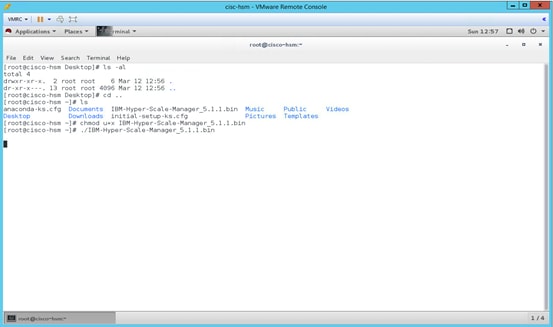
2. Select ports to be used by Hyper-Scale Manager.
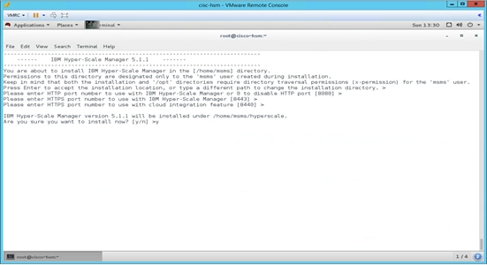
3. Accept the license agreement.

Information on the services installed is shown in the screenshot below.
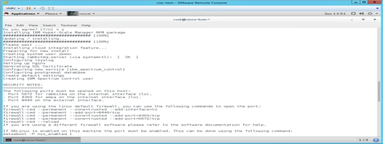
Information regarding the installation and firewall-cmd is shown below.
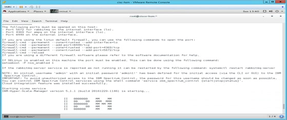
The complete installation of Hyper-Scale Manager is shown below.
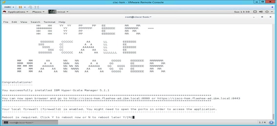
After the installation is complete, the next steps are to configure Hyper-Scale Manager to manage the FlashSystem A9000.
Configure Hyper-Scale Manager for the FlashSystem A9000
To configure the Hyper-Scale Manager, complete the following steps:
1. Run the IBM-Hyper-Scale Manager. The Welcome screen to new install of Hyper-Scale Manager displays.
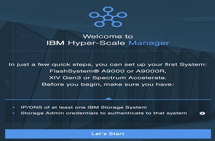
2. Enter the IP Address of FlashSystem A9000.
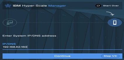
3. Enter a User name and Password for the Administrative User.

The Hyper-Scale Manager capability message is shown below.

4. Enter the Monitoring account for FlashSystem A9000.
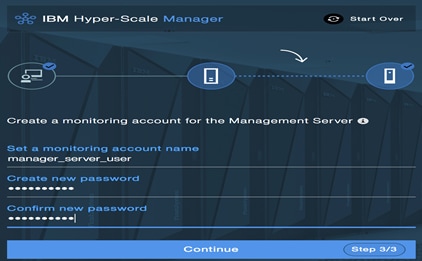
The Hyper-Scale Manager successful installation screen is shown below.
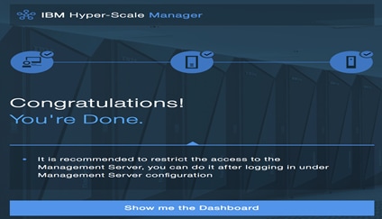
5. Select System under +New menu to add to an existing Hyper-Scale Manager.
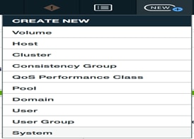
6. Enter a minimum of 1 IP Address for the FlashSystem A9000
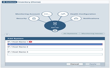
IBM Hyper-Scale Manager GUI Overview and ESXi Host Setup
1. Enter a User name and Password for the Administrative User.
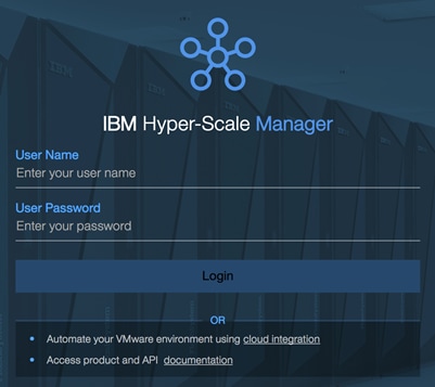
The Hyper-Scale Manager GUI is shown below.

The Hyper-Scale Manager GUI provides a new web-based management GUI for all members of the IBM Spectrum Accelerate family, including the XIV Storage System Gen3, IBM FlashSystem A9000 and IBM FlashSystem A9000R, as well as any IBM Spectrum Accelerate installations. The following functional highlights are included:
· Customizable Dashboard
· Context-oriented UI in a single-pane web-based application so that you can view all relevant information for every object at a glance
· Smart view of object relationships and dependencies in a visual map
· Instant object-centered management and monitoring
· Advanced filters for focusing on the required object
· Quick tracing of objects and fast navigation between objects
· Health score of all systems in the inventory
· Integrated statistics information
The Hyper-Scale Manager GUI Dashboard includes a Health Widget that displays the number of systems in the inventory and a high-level view of the health of the installed inventory. The Data Reduction widget display the data reduction savings as a result of compression and data deduplication of written data. The Capacity Widget display current and projected information about various capacity aspects of all systems in the inventory. Real-time Statics Widget displays latency and input/output operations per second (IOPS) information for all systems in the dashboard. You have the capability to see more granular performance and capacity metrics for individual, or groups of datastores over a wider timespan under the ‘Statistics View’ tab for up to a year.
Figure 30 IBM Hyper-Scale Manager Dashboard Overview
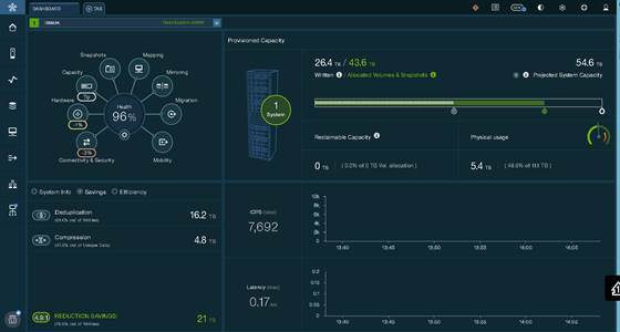
When the System has been added to the Hyper-Scale Manager, the next step is to complete the SAN zoning of the Cisco MCS 9148S switches so that the storage array and Cisco UCS servers are able to communicate.
To complete the SAN zoning for the Cisco MCS 9148S switches, complete the following steps:
1. Record the WWN’s of the array from within the Hyper-Scale Manager GUI,. This information can be found in the Hyper-Scale Manager GUI under System -> Actions -> Hardware -> View/Modify Ports in the right hand panel of the screen. Then select the Actions button for Port (Module 1) and select View/Edit FC Port and then at the bottom right hand side will be the WWPN:
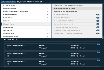
2. Select View/Edit FC Port to view WWPN.
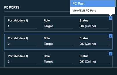
The WWPN is shown in lower left corner.
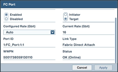
When the FlashSystem A9000 WWNs have been recorded, the Cisco MDS 9148S zonesets are created and activated. The WWNs of the UCS servers will automatically become visible to the IBM FlashSystem A9000 array (note that it can sometimes take up to 30 minutes for the UCS WWNs to become visible).
Adding a Cisco UCS Host
The next step is to create hosts within the Hyper-Scale Manager GUI. Volumes need to be connected to hosts and/or host groups in order for the two to communicate.
To create a Host within the Hyper-Scale Manager GUI, complete the following steps:
1. From the +New button, select Host.
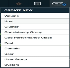
2. Create a Single Host.
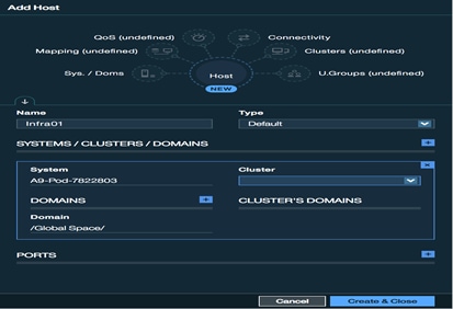
3. Select + to the right of Ports to add selection boxes for WWPN.

![]() In the screenshots above, you can see that a host is being created and the Cisco UCS servers WWNs have been added.
In the screenshots above, you can see that a host is being created and the Cisco UCS servers WWNs have been added.
Below, you can see a properly setup UCS host within the Hyper-Scale Manager GUI. Repeat the steps listed above to create hosts and configuring the Fibre Channel WWNs for all UCS servers.
Figure 31 Host with Two WWNs
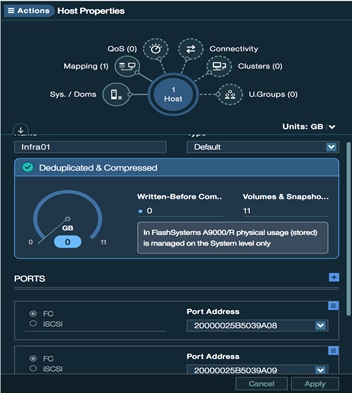
IBM FlashSystem A9000 Data Storage Layout
A key benefit of the IBM FlashSystem A9000 is that it rapidly enables customers to quickly and logically design their Vmware Horizon datastore implementation. The IBM FlashSystem A9000 offer unique patented designs to ensure maximum availability and that include IBM Variable Stripe RAID, IBM engineered error correction code (ECC), IBM optimized over-provisioning, advanced wear-leveling on IBM MicroLatency modules, write buffer and hardware offload, and IBM garbage collection (among other things) at the array level so Vmware administrators only need to name the datastore, input the size and then attach it to the appropriate host(s). In addition, the IBM FlashSystem A9000 array includes a vSphere Web-client plug-in that enables the administration of the array completely within the vSphere Web-client if they so choose.
For this Cisco Validated Design, we will break up our datastores by logical use case. This is often an overlooked benefit of an All-Flash Array – the ability to design your datastores with a logical layout rather than being forced to adhere to VM per datastore sizing limitations based upon storage performance bottlenecks. That is, several thousand VMs can be run from a single datastore without issue, though we recommend including fault tolerance into your design.
For the Vmware Horizon implementation used in this document, we elected to use the following datastore setup:
Table 13 Layout for the IBM FlashSystem A9000 Storage Array
| VDI Component |
Datastore Contents |
# of Datastores |
Datastore Size |
| VMware Horizon Infrastructure Datastore |
1 VMware vCenter 6 Appliance 2 Active Directory/DNS/DHCP Servers 4 VMware Horizon Connection/Replica Servers 1 Windows 2012 User Roaming Profile Share Server 1 Windows 2012 KMS Server 1 SQL Database Server 2 VSM Appliances (Cisco Nexus 1000V) 1 VSUM (Cisco Virtual Switch Update Manager) |
1 |
4 TB (4444GB) |
| VMware Horizon RDSH Datastore |
81 Windows Server 2012 R2 Servers for RDS Server Roles. 2100 User sessions. |
1 |
10 TB (11059 GB) |
| Non Persistent VMware Horizon VDI Desktop Datastore |
2900 Non-Persistent VDI Desktops |
2 |
10 TB (11059 GB) |
| ESXi Boot Datastore |
ESXi SAN boot for Cisco UCS B200 M4 Servers |
32 |
10 GB (11059 GB) |
![]() Storage was provisioned using the decimal data units representation (giga, tera) and to match the expected representation of VMware which uses the binary units representation (gibi, tebi) additional capacity was presented.
Storage was provisioned using the decimal data units representation (giga, tera) and to match the expected representation of VMware which uses the binary units representation (gibi, tebi) additional capacity was presented.
For example, below is the example of a InfraVOL created with 4TB datastore. The actual volume size selected is 4,444 Gb to get the desirable 4TB of size due to the decimal units calculation.
Figure 32 InfraVOL Data Store Provisioned 4 TB
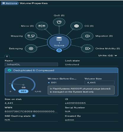
The following images provide examples of datastores created for data, SAN boot, and RDSH/VDI datastores.
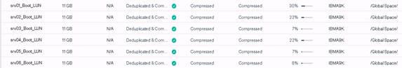
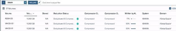
Create Volume and Data Stores on IBM FlashSystem A9000
Creating and even resizing a datastore on the FlashSystem A9000 array is incredibly simple and can be accomplished in just a few clicks.
To create and resized a datastore, complete the following steps:
1. Click the +New Button from the Top Navigation pane from within the Hyper-Scale Manager GUI.
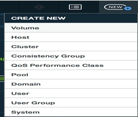
2. Name and size the Volume, select the System, Domain and Storage Pool to complete its creation.
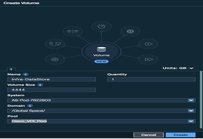
3. To connect the LUN to an ESXi host, select a newly created volume under the Volumes tab:
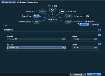
4. Select ‘Mapping’ from the hub to the right and then select Add at the bottom. Select the + Button to the right of Hosts to add one or more hosts to the Volume:
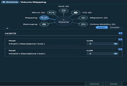
5. Storage setup has been completed and the datastore now needs to be added from within vSphere. From within the vSphere client, select a host from the Host Group that was connected to the volume in the previous step, go to Related Objects and then Datastore and click the icon to add the new datastore.
![]()
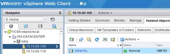
6. Select the VMFS option and click Next.
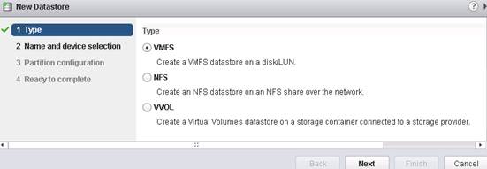
7. Name the datastore and select the appropriate volume from the list shown. It might be necessary to rescan the vHBA on the host in order to see a newly created datastore.
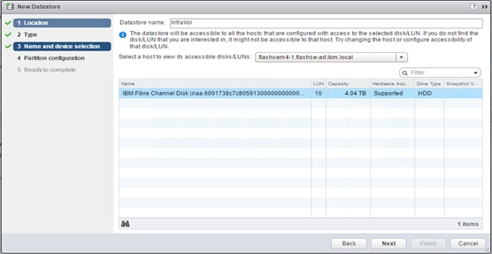
8. Leave the partition configuration options at default values and click Next.
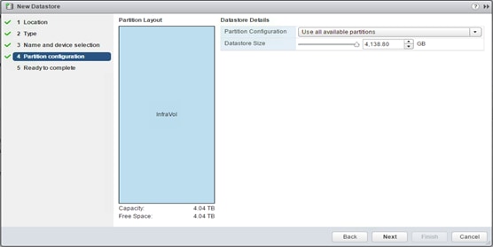
9. Click Finish to complete the datastore setup.
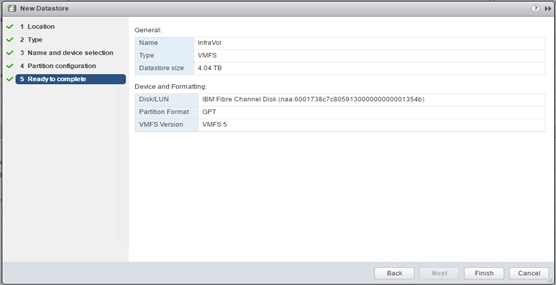
10. Repeat this process for each of the datastores listed in the Datastore.
Configure User Profile Manager Share on IBM FlashSystem A9000
A VDI user profile share was built using Windows Server 2012 R2 to closely mirror a production environment where user profiles are stored in a network location. The user profiles are created for the Login VSI users who sign in during the automated Knowledge Worker benchmark test runs. The server was hosted on the infrastructure datastore where our snapshot policies were applied for backing up the system.
The profiles were stored on a separate ProfileShare (E:) partition on the Windows 2012 Profile Server configured.
VDI- User Profiles
Figure 33 Profile Share Server for the Users Configured on the IBM FlashSystem A9000

Figure 34 RDSH Session Host User Profiles Configured on the same ProfileShare Server on IBM
FlashSystem A9000 Storage

Configure MDS 9100 Series
To configure the MDS 9100 series, complete the following steps:
![]() In this solution, we utilized the Cisco MDS 9148S Switches for Fiber Channel Switching. For racking, cable and initial setup of the MDS switches, please refer to the Quick Start Guide:
In this solution, we utilized the Cisco MDS 9148S Switches for Fiber Channel Switching. For racking, cable and initial setup of the MDS switches, please refer to the Quick Start Guide:
http://www.cisco.com/c/en/us/td/docs/switches/datacenter/mds9000/hw/9148/quick/guide/MDS_9148_QSG.pdf
1. When the MDS switch is racked and can be logged into, it can now be configured to communicate with the Cisco UCS Fabric Interconnects.
2. In this study, we used two separate fabrics each with their own unique VSAN. Fabric A is configured for VSAN300 while Fabric B for VSAN301. In our initial Cisco UCS configuration, you will see where we configured fiber cables on ports 13 and 16 and configured a FC port-channel. FI-A’s FC port channel is configured for VSAN300 and FI-B’s FC port-channel for VSAN301.
Figure 35 VSAN 300 Configured for Fabric A
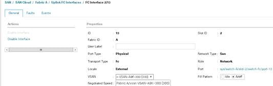
Figure 36 VSAN 301 Configured for Fabric B

![]() Physically, the Fabric Interconnects extended ports 13 and 14 run to the MDS switch ports 1 and 2.
Physically, the Fabric Interconnects extended ports 13 and 14 run to the MDS switch ports 1 and 2.
Figure 37 MDS Switch VSAN Configuration Connectivity
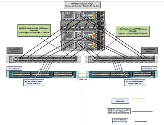
We used a total of 12 8Gb FC links, four from each grid controller, to the MDS 9148S SAN Switch for high availability and maximum throughput.
After the ports and port channels are configured, the next steps are to configure the zones and Active Zoneset Database in the MDS switches. The commands listed below detail how to add a single host on both 9148S A and B. You will need to configure all hosts that will access the IBM FlashSystem array in these commands. The entire MDS 9148S FC switch configuration is included in Appendix A.
MDS-A
Zoneset name A9000_VDI vsan 300
Member {ESXi hostname-fc0}
Exit
Zoneset activate name A9000_VDI vsan 300
Zone commit vsan 300
Exit
Copy running-config startup-config
MDS-B
Zoneset name A9000_VDI vsan 301
Member {ESXi hostname-fc1}
Exit
Zoneset activate name A9000_VDI vsan 301
Exit
Copy running-config startup-config
Installing and Configuring VMware ESXi 6.0
This section provides detailed instructions for installing VMware ESXi 6 Update1 in an environment. After the procedures are completed, two booted ESXi hosts will be provisioned.
Several methods exist for installing ESXi in a VMware environment. These procedures focus on how to use the built-in keyboard, video, mouse (KVM) console and virtual media features in Cisco UCS Manager to map remote installation media to individual servers and connect to their boot logical unit numbers (LUNs).
Download Cisco Custom Image for ESXi 6 Update2
To download the Cisco Custom Image for ESXi 6 Update 2, complete the following steps:
1. Click the following link vmware login page.
2. Type your email or customer number and the password and then click Log in.
3. Click on the following link:
4. https://my.vmware.com/web/vmware/details?downloadGroup=OEM-ESXI60U2-CISCO&productId=491
5. Click Download Now.
6. Save it to your destination folder.
![]() This ESXi 6.0 Cisco custom image includes updates for the fNIC and eNIC drivers. The versions that are part of this image are: eNIC: 2.3.0.10; fNIC: 1.6.0.28
This ESXi 6.0 Cisco custom image includes updates for the fNIC and eNIC drivers. The versions that are part of this image are: eNIC: 2.3.0.10; fNIC: 1.6.0.28
KVM Access to Hosts
To log in to the Cisco UCS environment, complete the following steps:
1. Log in to Cisco UCS Manager.
2. The IP KVM enables the administrator to begin the installation of the operating system (OS) through remote media. It is necessary to log in to the Cisco UCS environment to run the IP KVM.
3. Open a Web browser and enter the IP address for the Cisco UCS cluster address. This step launches the Cisco UCS Manager application.
4. Log in to Cisco UCS Manager by using the admin user name and password.
5. From the main menu, click the Servers tab.
6. Select Servers > Service Profiles > root > VM-Host-01.
7. Right-click VM-Host-01 and select KVM Console.
8. Repeat steps for 4-6 for all host servers.
Set Up VMware ESXi Installation
To prepare the server for the OS installation, complete the following steps on each ESXi host:
1. In the KVM window, click the Virtual Media tab.
2. Click Add Image.
3. Browse to the ESXi installer ISO image file and click Open.
4. Select the Mapped checkbox to map the newly added image.
5. Click the KVM tab to monitor the server boot.
6. Boot the server by selecting Boot Server and clicking OK. Then click OK again.
Install ESXi
To install VMware ESXi to the SAN-bootable LUN of the hosts, complete the following steps on each host:
1. On reboot, the machine detects the presence of the ESXi installation media. Select the ESXi installer from the menu that is displayed.
2. After the installer is finished loading, press Enter to continue with the installation.
3. Read and accept the end-user license agreement (EULA). Press F11 to accept and continue.
4. Select the IBM FlashSystem A9000 boot LUN.
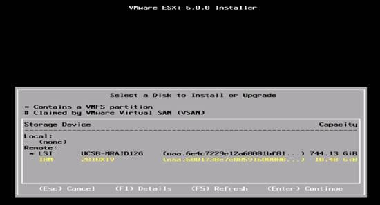
5. (IBM 2810XIV (naa.6001738c7c80591600000….) 10 GB that was previously set up as the installation disk for ESXi and press Enter to continue with the installation.
6. Select the appropriate keyboard layout and press Enter.
7. Enter and confirm the root password and press Enter.
8. The installer issues a warning that existing partitions will be removed from the volume. Press F11 to continue with the installation.
9. After the installation is complete, clear the Mapped checkbox (located in the Virtual Media tab of the KVM console) to unmap the ESXi installation image.
![]() The ESXi installation image must be unmapped to make sure that the server reboots into ESXi and not into the installer.
The ESXi installation image must be unmapped to make sure that the server reboots into ESXi and not into the installer.
10. The Virtual Media window might issue a warning stating that it is preferable to eject the media from the guest. Because the media cannot be ejected and it is read-only, click Yes to unmap the image.
11. From the KVM tab, press Enter to reboot the server.
Set Up Management Networking for ESXi Hosts
Adding a management network for each VMware host is necessary for managing the host.
To configure the ESXi host with access to the management network, complete the following steps:
1. After the server has finished rebooting, press F2 to customize the system.
2. Log in as root and enter the corresponding password.
3. Select the Configure the Management Network option and press Enter.
4. Select the VLAN (Optional) option and press Enter.
5. Enter the VLAN in-band management ID and press Enter.
6. From the Configure Management Network menu, select IP Configuration and press Enter.
7. Select the Set Static IP Address and Network Configuration option by using the space bar.
8. Enter the IP address for managing the first ESXi host.
9. Enter the subnet mask for the first ESXi host.
10. Enter the default gateway for the first ESXi host.
11. Press Enter to accept the changes to the IP configuration.
12. Select the IPv6 Configuration option and press Enter.
13. Using the spacebar, unselect Enable IPv6 (restart required) and press Enter.
14. Select the DNS Configuration option and press Enter.
![]() Since the IP address is assigned manually, the DNS information must also be entered manually.
Since the IP address is assigned manually, the DNS information must also be entered manually.
15. Enter the IP address of the primary DNS server.
16. Optional: Enter the IP address of the secondary DNS server.
17. Enter the fully qualified domain name (FQDN) for the first ESXi host.
18. Press Enter to accept the changes to the DNS configuration.
19. Press Esc to exit the Configure Management Network submenu.
20. Press Y to confirm the changes and return to the main menu.
21. The ESXi host reboots. After reboot, press F2 and log back in as root.
22. Select Test Management Network to verify that the management network is set up correctly and press Enter.
23. Press Enter to run the test.
24. Press Enter to exit the window.
25. Press Esc to log out of the VMware console.
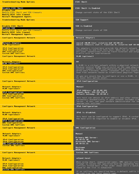
Download VMware vSphere Client
To download the VMware vSphere Client, complete the following steps:
1. Open a web browser on the management workstation and navigate to the VM-Host-01 management IP address.
2. Download and install the vSphere Client.
![]() This application is downloaded from the VMware website and Internet access is required on the management workstation.
This application is downloaded from the VMware website and Internet access is required on the management workstation.
Download VMware vSphere CLI 6
To download VMware vSphere CLI 6, complete the following steps:
1. Click the following link VMware vSphere CLI 6.0
2. Select your OS and click Download.
3. Save it to your destination folder.
4. Run the VMware-vSphere-CLI.exe
5. Click Next.
6. Accept the terms for the license and click Next.
7. Click Next on the Destination Folder screen.
8. Click Install.
9. Click Finish.
![]() Install VMware vSphere CLI 6.0 on the management workstation.
Install VMware vSphere CLI 6.0 on the management workstation.
10. Log in to VMware ESXi Hosts by Using VMware vSphere Client.
Log in to VMware ESXi Hosts by using VMware vSphere Client
To log in to the VM-Host-01 ESXi host by using the VMware vSphere Client, complete the following steps:
1. Open the recently downloaded VMware vSphere Client and enter the IP address of VM-Host-01 as the host you are trying to connect to: <<var_vm_host_01_ip>>.
2. Enter root for the user name.
3. Enter the root password.
4. Click Login to connect.
Download Updated Cisco VIC eNIC Drivers
To download the Cisco virtual interface card (VIC) eNIC and fNIC drivers, complete the following steps:
![]() The eNIC version is 2.3.0.7 and the fNIC version is 1.6.0.28 were used in this configuration
The eNIC version is 2.3.0.7 and the fNIC version is 1.6.0.28 were used in this configuration
1. Open a Web browser on the management workstation and navigate to:
2. Download the Cisco eNIC and fNIC driver bundle.
3. Open the eNIC driver bundle. This bundle includes the VMware driver bundle which will be uploaded to ESXi hosts.
4. Open the fNIC driver bundle. This bundle includes the VMware driver bundle which will be uploaded to ESXi hosts.
5. Save the location of these driver bundles for uploading to ESXi in the next section.
![]() If the link above has changed, go to www.cisco.com for the latest ISO image of Cisco UCS-related drivers. This ISO will either have the drivers included or may have an HTML file with the location of the latest network drivers.
If the link above has changed, go to www.cisco.com for the latest ISO image of Cisco UCS-related drivers. This ISO will either have the drivers included or may have an HTML file with the location of the latest network drivers.
Load Updated Cisco VIC eNIC and fNIC Drivers
To install VMware VIC Drivers on the ESXi host servers, complete the following steps:
1. From each vSphere Client, select the host in the inventory.
2. Click the Summary tab to view the environment summary.
3. From Resources > Storage, right-click datastore1 and select Browse Datastore.
4. Click the fourth button and select Upload File.
5. Navigate to the saved location for each downloaded VIC driver and select :
- ESXi6.0_fnic_driver_1.6.0.28-4179603.zip or
- ESXi6.0_enic-2.3.0.7-3642661.zip
6. Click Open on each and click Yes to upload the file to datastore1.
7. Click the fourth button and select Upload File.
8. Make sure the files have been uploaded to both ESXi hosts.
9. From the management workstation, open the VMware vSphere Remote CLI that was previously installed.
10. At the command prompt, run the following commands to account for each host
![]() To get the host thumbprint, type the command without the –-thumbprint option, then copy and paste the thumbprint into the command.
To get the host thumbprint, type the command without the –-thumbprint option, then copy and paste the thumbprint into the command.
esxcli –s <<var_vm_host_ip>> -u root –p <<var_password>> --thumbprint <host_thumbprint> software vib update -d /vmfs/volumes/datastore1/ESXi6.0_enic-2.3.0.7-offline_bundle-4303638.zip
esxcli –s <<var_vm_host_ip>> -u root –p <<var_password>> --thumbprint <host_thumbprint> software vib update -d /vmfs/volumes/datastore1/ fnic_driver_1.6.0.28-offline_bundle-4179603.zip
11. Back in the vSphere Client for each host, right click the host and select Reboot.
12. Click Yes and OK to reboot the host.
13. Log back into each host with vSphere Client.
![]() Verify the eNIC driver version installed by entering vmkload_mod –s enic and vmkload_mod –s fNIC at the command prompt.
Verify the eNIC driver version installed by entering vmkload_mod –s enic and vmkload_mod –s fNIC at the command prompt.
Install and Configure VMware vCenter Appliance
Log in to the VM-Host-01 ESXi host by using the VMware vSphere Client and complete the following steps:
1. Open the recently downloaded VMware vSphere Client and enter the IP address of VM-Host-01 as the host you are trying to connect to.
2. Enter root for the user name.
3. Enter the root password.
4. Click Login to connect.
To build the VMWare vCenter VM, complete the following steps:
1. From the vSphere 6 download page on the VMware Web site, download the vCenter ISO file for the vCenter Server appliance onto your system.
2. Open the vSphere ISO via Windows Explorer and double-click the vcsa-setup.htm file. Install VCSA Appliance from Installer
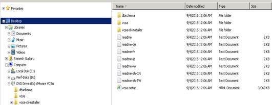
A browser will open with an option to Install.
3. Click Install.
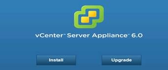
4. Follow the onscreen prompts. Accept EULA.
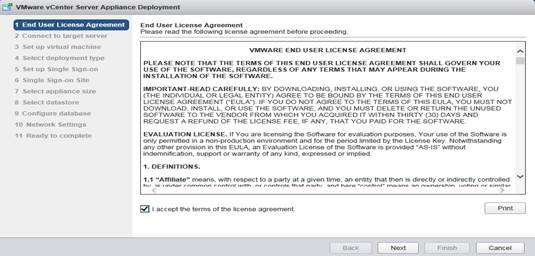
5. Enter the IP of the ESXi host the vCenter Appliance will reside. Click Next. Provide Host IP or FQDN and User Name, Password Credentials of the Host to Connect.
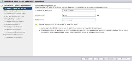
6. Click Yes to accept Certificate Warning.
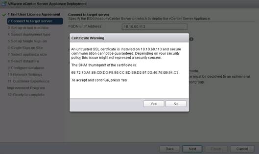
7. Provide a name for the vCenter appliance, then click Next to continue.
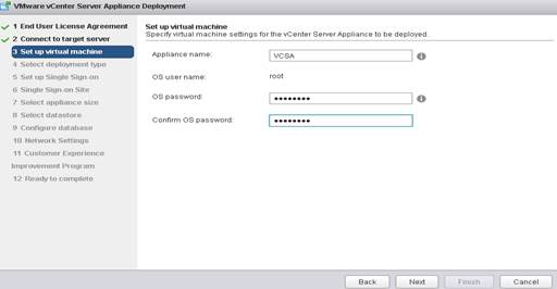
8. Select Install vCenter Server with and Embedded Platform Services Controller (unless your environment already has a PSC).
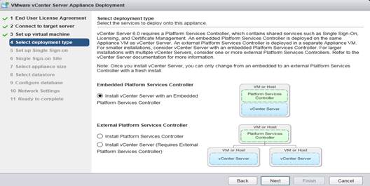
9. Create a new SSO domain (unless your environment already has and SSO domain. Multiple SSO domains can co-exist).
10. Provide Single Sign On Password and Site Name Credentials.
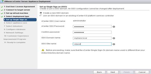
11. Select the proper appliance size for your deployment. In our study, Large was selected.
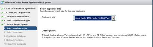
12. Select the Data store
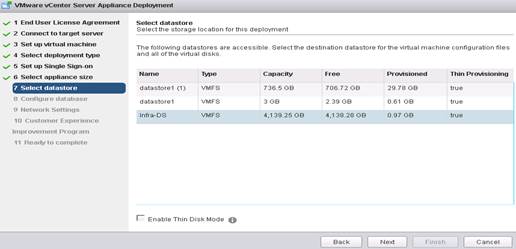
![]() In our study we used the embedded PostgreSQL database.
In our study we used the embedded PostgreSQL database.
13. Select Use an embedded database (PostgreSQL).
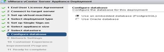
14. Enter Network Settings for appliance.
![]() It is important to note at this step that you should create a DNS A record for your appliance prior to running the install. The services will fail to startup and your install will fail if it cannot resolve properly.
It is important to note at this step that you should create a DNS A record for your appliance prior to running the install. The services will fail to startup and your install will fail if it cannot resolve properly.
15. Provide the Necessary Network Gateways and DNS Server Information. Review the install settings and click Finish.
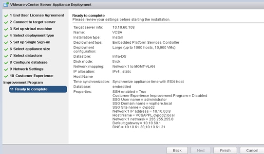
16. When your install completes successfully, you can now login to your Web Client and begin adding hosts and configuring clusters.
17. Login in to VCenter Appliances Web GUI:
https://10.10.60.8/vsphere-client. Or use FQDN https://VCSA.vdipod.local/vsphere-client as administrator
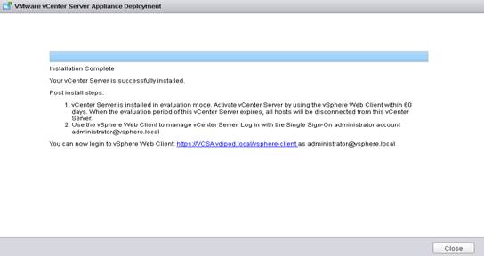
18. Log into the vSphere Web Client.
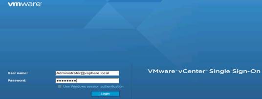
19. Login using IP Address of the Appliance and Download vSphere.

20. Click the link labeled Log in to vSphere Web Client.
21. If prompted, run the VMWare Remote Console Plug-in.
22. Log in using the root user name and password.
23. Click the vCenter link on the left panel.
24. Login vSphere Web GUI.
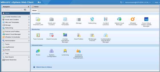
25. Click the Datacenters link on the left panel.
26. To create a Datacenter, click the icon in the center pane which has the green plus symbol above it.
The screenshot below shows an example of a VDI-DC Data Center.
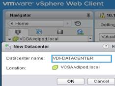
27. Type VDI-DC as the Datacenter name.
28. Click the vCenter server available in the list. Click OK to continue.
29. Create a Cluster.
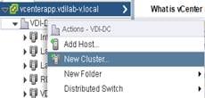
30. Right-click Datacenters > VDI-DATACENTER in the list in the center pane, then click New Cluster.
31. Name the cluster Infra-CL.
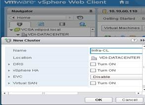
32. Select DRS. Retain the default values.
33. Select vSphere HA. Retain the default values. Configure Cluster Specific Setting.
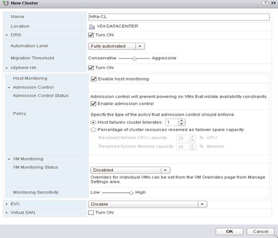
![]() If mixing Cisco UCS B 200 M4 servers within a vCenter cluster, it is necessary to enable VMware Enhanced vMotion Compatibility (EVC) mode. For more information about setting up EVC mode, refer to Enhanced vMotion Compatibility (EVC) Processor Support.
If mixing Cisco UCS B 200 M4 servers within a vCenter cluster, it is necessary to enable VMware Enhanced vMotion Compatibility (EVC) mode. For more information about setting up EVC mode, refer to Enhanced vMotion Compatibility (EVC) Processor Support.
34. Click OK to create the new cluster.
35. Click VDI-DC in the left pane.
36. Add a ESXi Host.
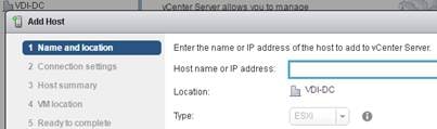
37. Right-click Infra in the center pane and click Add Host.
38. Type the host IP address and click Next.
39. Type root as the user name and root password as the password. Click Next to Continue.

40. Click Yes to accept the certificate.
41. Review the host details and click Next to continue.
42. Assign a license, and click Next to continue.
43. Click Next to continue.
44. Click Next to continue.
45. Review the configuration parameters then click Finish to add the host.
46. Repeat this for the other hosts and clusters
47. When completed, the vCenter cluster configuration is comprised of the following clusters, including a cluster to manage the workload launcher hosts:
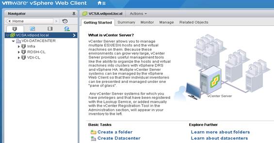
Install and Configure VSUM and Cisco Nexus 1000v
Install Cisco Virtual Switch Update Manager
Verifying the Authenticity of the Cisco-Signed Image (Optional)
Before you install the Cisco Nexus1000v-vsum.1.5.x-pkg.zip image, you have the option to validate its authenticity. In the zip file, there is a signature.txt file that contains an SHA-512 signature and an executable script that can be used to verify the authenticity of the Nexus1000v-vsum.1.5.x-pkg.zip image.
To set up the primary Cisco Nexus 1000V VSM on the Cisco Nexus 1110-X A, complete the following steps:
![]() Verifying the authenticity of an image is optional. You can still install the image without validating its authenticity.
Verifying the authenticity of an image is optional. You can still install the image without validating its authenticity.
1. Copy the following files to a directory on the Linux machine:
- Nexus1000v-vsum.1.5.x-pkg.zip image
- signature.txt file
- cisco_n1k_image_validation_v_1_5_x script
2. Make sure the script is executable.
- chmod 755 cisco_n1k_image_validation_v_1_5_x
3. Run the script.
- ./cisco_n1k_image_validation_v_1_5_x -s signature.txt Nexus1000v-vsum.1.5.x-pkg.zip
4. Run the script.
- ./cisco_n1k_image_validation_v_1_5_x -s signature.txt Nexus1000v-vsum.1.5.x-pkg.zip
5. Check the output. If the validation is successful, the following message displays:
Authenticity of Cisco-signed image Nexus1000v-vsum.1.5.x-pkg.zip has been successfully verified!
Install Cisco Virtual Switch Update Manager
VMware vSphere Web Client
To install the Cisco Virtual Switch Upgrade Manager from OVA in the VMware virtual environment, complete the following steps:
1. Log into the VMware vSphere Web Client.
2. In the pane on the right, click VMs and Templates.
3. In the center pane, select Actions > Deploy OVF Template.
4. Select Browse and browse to and select the Nexus1000v-vsum.1.5.x.ova file.
5. Click Open.
6. Click Next.
7. Select the Cisco Nexus 1000v OVF file to install.
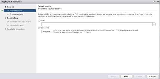
8. Review the details and click Next.
9. Review and click Next.
10. Click Accept to accept the License Agreement and click Next.
11. Name the Virtual Machine, select the VDI-DC datacenter and click Next.
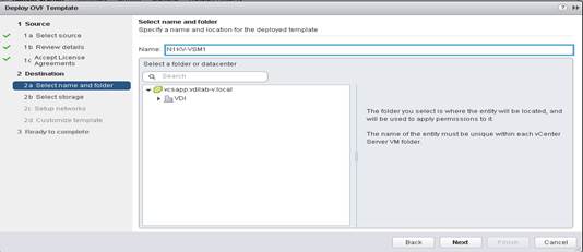
12. Select the Infra cluster and click Next.
13. Select Infra-Datastore and the Thin Provision virtual disk format and click Next.
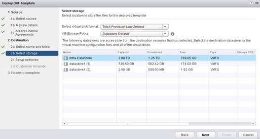
14. Select the MGMT Network and click Next.
15. Fill in the Networking Properties.
16. Expand the vCenter Properties and fill in the fields.
17. Click Next.
18. Review all settings and click Finish.
19. Wait for the Deploy OVF template task to complete.
20. Select the Home button in VMware vSphere Web Client and select Hosts and Clusters.
21. Expand the Infrastructure cluster and select the Virtual Switch Update Manager VM.
22. In the center pane, select Launch Remote Console. If a security warning pops up, click Allow.
23. If a security certificate warning pops up, click Connect Anyway.
24. Power on the Virtual Switch Update Manager VM.
25. When the VM has completely booted up, log out and log back into the VMware vSphere Web Client.
26. Review and click Next to install the click Nexus 1000V.
27. Customize the template.
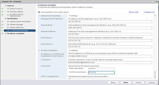
About the Cisco VSUM GUI
The following lists the details of the Cisco VSUM GUI:
· Cisco VSUM is a virtual appliance that is registered as a plug-in to the VMware vCenter Server.
· The Cisco VSUM is the GUI that you use to install, migrate, monitor, and upgrade the VSMs in high availability (HA) or standalone mode and the VEMs on ESX/ESXi hosts.
Figure 38 VMware vSphere Web Client—Home Page
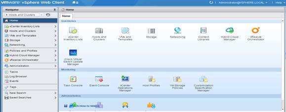
Figure 39 Cisco VSUM—Home Page
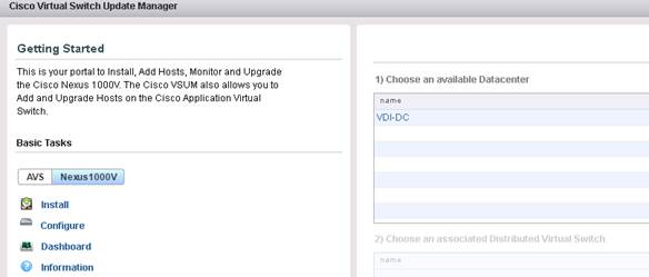
Install Cisco Nexus 1000V using Cisco VSUM
VMware vSphere Web Client
To install the Cisco Nexus 1000V switch by creating a new VSM, complete the following steps:
![]() Optionally, an existing VSM can be used that is provided by a Cisco Nexus Cloud Services Platform (CSP).
Optionally, an existing VSM can be used that is provided by a Cisco Nexus Cloud Services Platform (CSP).
1. Log in to VMware vSphere Web Client and choose Home > Cisco Virtual Switch Update Manager > Nexus 1000V > Install, and then choose the data center. The installation screen appears.
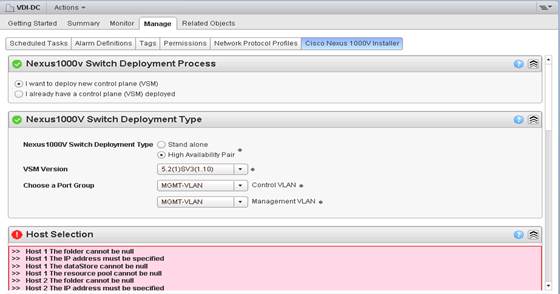
2. In the Nexus 1000v Switch Deployment area, choose I want to deploy new control plane (VSM).
3. In the Cisco Nexus 1000V Switch Deployment Type area, install the switches as an HA pair. By default, the High Availability Pair is selected.
4. Choose the control port group for the switch.
5. Choose the management port group for the switch.
![]() The Cisco Nexus 1000V VSM uses the management network to communicate with vCenter Server and ESXi. The management and control port group can use the same VLAN.
The Cisco Nexus 1000V VSM uses the management network to communicate with vCenter Server and ESXi. The management and control port group can use the same VLAN.
6. In the Host Selection area, click Suggest to choose two hosts based on the details provided in the Cisco Nexus 1000V Switch Deployment Type area. The IP address of the hosts on which the switch will be deployed.
7. The primary switch is deployed on Infrastructure Host 1 and the secondary switch is deployed on Infrastructure Host 2. Click Pick a Host to override the system choices.
8. Choose the system-selected datastore that you want to override. Choose IBM Infra-Datastore (Infra-DS) as the datastore for each host.
9. Provide Host IP address where the Virtual Ethernet Modules to be created. (note it requires two ESXI hosts for installing VEM primary and secondary modules for redundancy purpose)
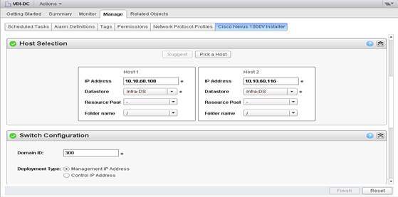
10. In the Switch Configuration area, enter 300 as the domain ID for the switch.
11. The domain ID is common for both the primary and secondary switches and it should be unique for every new switch. The range for the domain is from 1 to 1023.
12. In the Virtual Supervisor Module (VSM) configuration area, enter the Switch Name, IP Address, Subnet Mask, and Gateway Address.
13. Do not select Default Port Profiles.
14. Enter the Password and Confirm Password for Admin.
15. Provide switch name, IP address and provide password.
![]() No special characters allowed.
No special characters allowed.
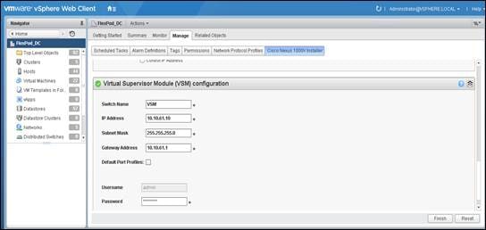
16. Click Finish to install the Cisco Nexus 1000V switch.
![]() The Cisco Nexus 1000V installation is confirmed when the primary task Create Nexus 1000v Switch has the status Completed. A typical installation of the switch takes about 4 minutes.
The Cisco Nexus 1000V installation is confirmed when the primary task Create Nexus 1000v Switch has the status Completed. A typical installation of the switch takes about 4 minutes.
Perform Base Configuration of the Primary VSM
SSH Connection to Primary VSM
To perform the base configuration of the primary VSM, complete the following steps:
1. Using an SSH client, log in to the primary Cisco Nexus 1000V VSM as admin.
2. Run the following configuration commands:
![]() Any VLAN that has a VMKernal port should be assigned as a system VLAN on both the uplink and the vEthernet ports of the virtual switch.
Any VLAN that has a VMKernal port should be assigned as a system VLAN on both the uplink and the vEthernet ports of the virtual switch.
config t
ntp server <<var_switch_a_ntp_ip>> use-vrf management
ntp server <<var_switch_b_ntp_ip>> use-vrf management
vlan <<var_ib-mgmt_vlan_id>> 60
name IB-MGMT-VLAN
vlan <<var_vmotion_vlan_id>> 66
name vMotion-VLAN
![]() The Cisco Nexus 1000V is currently limited to 1024 Max ports per profile. This solution is comprised of 3500 plus virtual desktop machines for the user workload and requires four dedicated port-profiles(VDI1-VLAN1, VDI2-VLAN, VDI3-VLAN).
The Cisco Nexus 1000V is currently limited to 1024 Max ports per profile. This solution is comprised of 3500 plus virtual desktop machines for the user workload and requires four dedicated port-profiles(VDI1-VLAN1, VDI2-VLAN, VDI3-VLAN).
vlan <<var_vdi_vlan_id>> 102
name VDI1-VLAN
vlan <<var_vdi_vlan_id>> 102
name VDI2-VLAN
vlan <<var_vdi_vlan_id>> 102
name VDI3-VLAN
vlan <<var_vm-traffic_vlan_id>> 61
name Infra-VLAN
vlan <<var_vm-traffic_vlan_id>> 164
name OB-MMGMT-VLAN
vlan <<var_native_vlan_id>> 1
name Native-VLAN
exit
port-profile type ethernet system-uplink
vmware port-group
switchport mode trunk
switchport trunk native vlan <<var_native_vlan_id>> 1
switchport trunk allowed vlan <<var_ib-mgmt_vlan_id>>, <<var_nfs_vlan_id>>, <<var_vmotion_vlan_id>>, <<var_vm-infra_vlan_id>> 60-66
channel-group auto mode on mac-pinning
no shutdown
system vlan <<var_ib-mgmt_vlan_id>>, <<var_nfs_vlan_id>>, <<var_vmotion_vlan_id>>, <<var_vm-infra_vlan_id>> 60-66
system mtu 9000
state enabled
port-profile type vethernet IB-MGMT-VLAN
vmware port-group
switchport mode access
switchport access vlan <<var_ib-mgmt_vlan_id>> 60
no shutdown
system vlan <<var_ib-mgmt_vlan_id>> 60
state enabled
port-profile type vethernet vMotion
vmware port-group
switchport mode access
switchport access vlan <<var_vmotion_vlan_id>> 66
no shutdown
system vlan <<var_vmotion_vlan_id>> 66
state enabled
port-profile type vethernet INFRA-VLAN
vmware port-group
switchport mode access
switchport access vlan <<var_infra_vlan_id>> 61
no shutdown
system vlan <<var_infra_vlan_id>> 61
state enabled
port-profile type vethernet n1kv-L3
capability l3control
vmware port-group
switchport mode access
port-profile type vethernet VDI1-VLAN
vmware port-group
switchport mode access
switchport access vlan <<var_vdi1-VLAN_id>> 102
no shutdown
max-ports 1024
system vlan <<var_vdi2-VLAN_id>> 102
state enabled
port-profile type vethernet VDI2-VLAN
vmware port-group
switchport mode access
switchport access vlan <<var_vdi2-VLAN_id>> 102
no shutdown
max-ports 1024
system vlan <<var_vdi_1_vlan_id>> 102
state enabled
port-profile type vethernet VDI3-VLAN
vmware port-group
switchport mode access
switchport access vlan <<var_vdi3-VLAN_id>> 102
no shutdown
max-ports 1024
switchport access vlan <<var_OB-MGMT-VLAN_vlan_id>> 164
no shutdown
system vlan <<var_OB-MGMT-VLAN_vlan_id>> 164
state enabled
exit
copy run start
Add VMware ESXi Hosts to Cisco Nexus 1000V
VMware vSphere Web Client
To and VMware ESXi hosts, complete the following steps:
1. Back in the VMware vSphere Web Client, from the Home tab, select Cisco Virtual Switch Update Manager.
2. Under Basic Tasks, select Nexus 1000V.
3. Select Configure.
4. Select the VDI-DC datacenter on the right.
5. Select the VSM on the lower right.
6. Click Manage.
7. In the center pane, select the Add Host tab.
8. Expand the Infrastructure ESXi Cluster and select one of the Infrastructure Management Hosts.
9. Click Suggest.
10. Scroll down to Physical NIC Migration and expand each ESXi host.
11. On both hosts, unselect vmnic0, and select vmnic1. For vmnic1, select the system-uplink Profile.
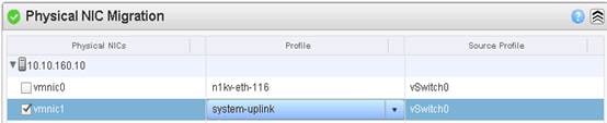
12. Scroll down to VM Kernel NIC Setup and expand both ESXi hosts.
13. All VMkernel ports should already have the appropriate checkboxes selected.
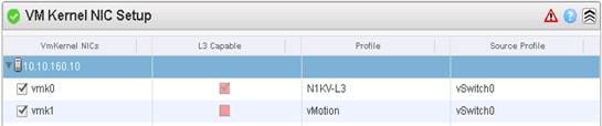
14. Scroll down to VM Migration and expand both ESXi hosts.
15. Click Finish.
![]() The progress of the virtual switch installation can be monitored from the c# interface. Migrate ESXi Host Redundant Network Ports to Cisco Nexus 1000V
The progress of the virtual switch installation can be monitored from the c# interface. Migrate ESXi Host Redundant Network Ports to Cisco Nexus 1000V
To migrate the ESXi host redundant network ports, complete the following steps:
1. In the VMware vSphere Web Client window, select Home > Hosts and Clusters.
2. On the left expand the Datacenter and cluster, and select the first VMware ESXi host.
3. In the center pane, select the Manage tab, then select Networking.
4. Select vSwitch0. All of the port groups on vSwitch0 should be empty. Click the red X under Virtual switches to delete vSwitch0.
5. Click Yes to remove vSwitch0. It may be necessary to refresh the Web Client to see the deletion.
6. The Nexus 1000V VSM should now be the only virtual switch. Select it and select the third icon above it under Virtual switches (Manage the physical network adapters connected to the selected switch).
7. Click the green plus sign to add an adapter.
8. For UpLink01, select the system-uplink port group and make sure vmnic0 is the Network adapter. Click OK.
9. Click OK to complete adding the Uplink. It may be necessary to refresh the Web Client to see the addition.
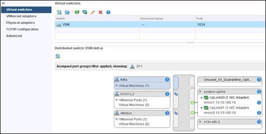
10. Repeat this procedure for the other ESXi host.
11. From the SSH client that is connected to the Cisco Nexus 1000V, run show interface status to verify that all interfaces and port channels have been correctly configured.
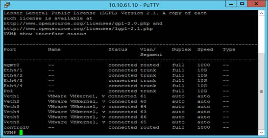
12. Run show module and verify that the one ESXi host is present as a module.
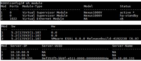
13. Repeat the above steps to migrate the remaining ESXi hosts to the Nexus 1000V.
14. Run: copy run start.
Cisco Nexus 1000V vTracker
The vTracker provides various views that are based on the data sourced from the vCenter, the Cisco Discovery Protocol (CDP), and other related systems connected with the virtual switch. You can use vTracker to troubleshoot, monitor, and maintain the systems.
Using vTracker show commands, you can access consolidated network information across the following views:
· Upstream View—Provides information on all the virtual ports connected to an upstream physical switch. The view is from top of the network to the bottom.
· VM View—Supports two sets of data:
- VM vNIC View—Provides information about the virtual machines (VMs) that are managed by the Cisco Nexus 1000V switch. The vNIC view is from the bottom to the top of the network.
- VM Info View—VM Info View—Provides information about all the VMs that run on each server module.
· Module pNIC View—Provides information about the physical network interface cards (pNIC) that are connected to each Virtual Ethernet Module (VEM).
· VLAN View—Provides information about all the VMs that are connected to specific VLANs.
· vMotion View—Provides information about all the ongoing and previous VM migration events.
The vTracker feature on the Cisco Nexus 1000V switch provides information about the virtual network. environment. To connect SSH to the primary VSM, complete the following step:
1. From an SSH interface connected to the Cisco Nexus 1000V VSM, enter the following:
config t
feature vtracker
copy run start
show vtracker upstream-view
show vtracker vm-view vnic
show vtracker vm-view info
show vtracker module-view pnic
show vtracker vlan-view
copy run start
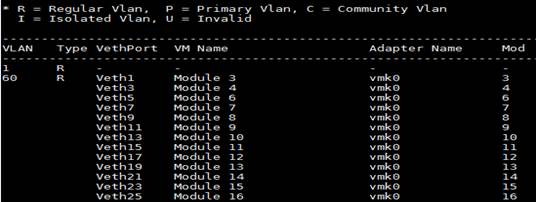
Building the Virtual Machines and Environment for Workload Testing
Software Infrastructure Configuration
This section details how to configure the software infrastructure components that comprise this solution.
Install and configure the infrastructure virtual machines by following the process provided in the table below:
Table 14 Software Infrastructure Configuration
| Configuration |
Operating System |
Virtual CPU |
Memory |
Disk Size |
Network |
| vCenter Server Appliance |
VCSA- SUSE Linux |
8 |
32 |
490
|
MGMT-VLAN |
| Active Directory Domain Controllers/DHCP/DNS (2) |
Microsoft Windows 2012 R2 |
4 |
8 |
60 |
Infra-VLAN
|
| VMware Horizon Connection Server |
Microsoft Windows 2012 R2 |
4 |
12 |
60 |
Infra-VLAN
|
| VMware Horizon Composer Server-1 |
Microsoft Windows 2012 R2 |
4 |
12 |
40 |
Infra-VLAN
|
| VMware Horizon Replica Server-1 |
Microsoft Windows 2012 R2 |
4 |
8 |
40 |
Infra-VLAN
|
| VMware Horizon Replica Server-2 |
Microsoft Windows 2012 R2 |
4 |
8 |
40 |
Infra-VLAN
|
| VMware Horizon Replica Server-3 |
Microsoft Windows 2012 R2 |
4 |
8 |
40 |
Infra-VLAN
|
| SQL Server |
Microsoft Windows 2012 R2 |
4 |
12 |
60 |
Infra-VLAN
|
Preparing the Master Image
This section provides guidance around creating the golden (or master) images for the environment. VMs for the master targets must first be installed with the software components needed to build the golden images. For this CVD, the images contain the basics needed to run the Login VSI workload.
To prepare the master VMs for the Hosted Virtual Desktops (HVDs) and Hosted Shared Desktops (HSDs), there are three major steps: installing the PVS Target Device x64 software, installing the Virtual Delivery Agents (VDAs), and installing application software.
The master target HVD(VDI) and HSD(RDS) VMs were configured as listed in the table below:
Table 15 Master Image Configuration
| Configuration |
Operating System |
Virtual CPU |
Memory |
Disk Size |
Network |
Additional Software |
| RDSH Virtual Machines |
Microsoft Windows Server 2012 Standard |
6 |
24 |
40 |
VMXNET3 VDI-VLAN
|
Microsoft Office 2016. Login VSI 4.1.5 (Knowledge Worker workload) |
| VDI Virtual Machines |
Microsoft Windows 10 64-Bit LTSB Version 1607 |
2 |
2 (Reserved) |
24
|
VMXNET3 VDI-VLAN (VSM) |
Microsoft Office 2016. Login VSI 4.1.5 (Knowledge Worker workload) |
Installing and Configuring VMware Horizon Environment
This section details the installation of the VMware core components of the Horizon Connection Server and Replica Servers. This CVD installs 1 VMware Horizon Connection server and 3 VMware Horizon Replica Servers to support both remote desktop server hosted sessions (RDSH), non-persistent virtual desktops (VDI) based on the best practices from VMware.
The prerequisites for installing the Horizon Connection server or Composer server is to have Windows 2008 or 2012 servers ready. In this study, we have used Windows 2012 server R2 for Horizon Connection Server, Replica Servers, and Composer Server.
VMware Horizon Connection Server Configuration
To configure the VMware View Connection Server, complete the following steps:
1. Download the Horizon Connection server installer from VMware and click Install on the Connection Server Windows Server Image. In this study, we used version Connection Server 7.0.3 build.4709455.
https://my.vmware.com/en/web/vmware/info/slug/desktop_end_user_computing/vmware_horizon/7_0
2. Click the Connection Server installer.
3. Click Next.
4. Accept the terms in the License Agreement.
5. Click Next.
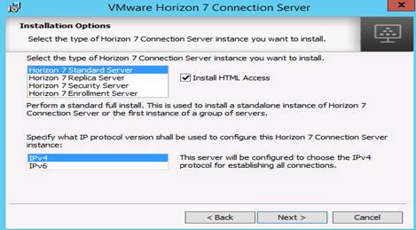
6. Select the Standard Server.
![]() To install additional VMware Horizon Replica servers, during the installation, select Horizon 7 Connection Server Option to sync the Replica Servers with the existing Standard server by providing View Connection Server’s FQDN or IP address.
To install additional VMware Horizon Replica servers, during the installation, select Horizon 7 Connection Server Option to sync the Replica Servers with the existing Standard server by providing View Connection Server’s FQDN or IP address.
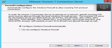
7. Configure the Windows firewall automatically.
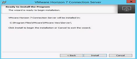
8. Click Install.
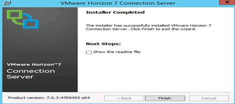
9. Click Finish to complete the Horizon Connection Server installation.
Horizon VMware Replica Server Creation
To install Horizon Replica Server and additional Replica servers, complete the following steps:
1. Follow the steps in VMware Horizon Connection Server Configuration. During the installation, select the Replica Server option in order to configure this server as a Replica Server and complete all other steps shown above.
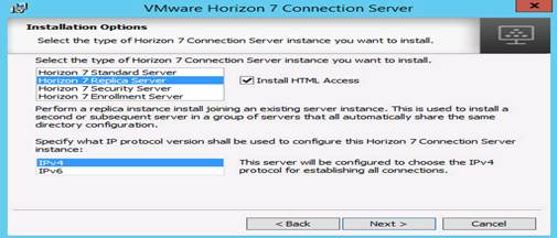
2. Click Next and follow the steps (shown for Horizon Standard server ) to complete installing additional Horizon Replica Servers.
Install VMware Horizon Composer Server
To install the VMware Horizon Composer Server, complete the following steps:
1. Download the Composer installer from VMware and click Install on the Composer Windows server Image. In this study, we used Composer 7.0.3 build.4698622.
https://my.vmware.com/en/web/vmware/info/slug/desktop_end_user_computing/vmware_horizon/7_0
https://my.vmware.com/web/vmware/details?downloadGroup=VIEW-703-STD&productId=577&rPId=13974
2. Click the Install Horizon Composer installer and click Next.
3. Accept the License Agreement and click Next.
4. Click Install.
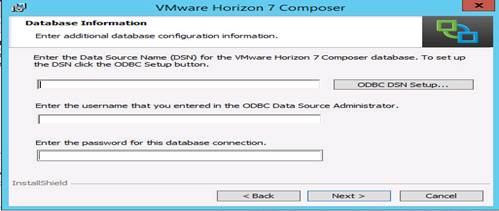
5. Provide ODBC database connection details and click Next.
The VMware Horizon 7 Composer is being installed.
6. Click Finish.
Create the Golden Image for VMware Horizon RDS Deployment
You need to create the Golden Image as a prerequisite to install and configure server 2008 or 2012. To create the Golden Image, complete the following steps:
![]() We used Microsoft 2012 R2 Standard Edition to configure the RDS Server Roles for RDSH VMs to be deployed from the Master image.
We used Microsoft 2012 R2 Standard Edition to configure the RDS Server Roles for RDSH VMs to be deployed from the Master image.
1. Login to Windows 2012 RDS Server base VM (Master Image) and click Server Properties and then click Add Roles and Features.
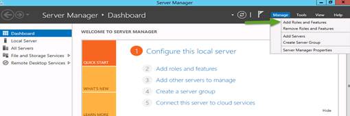
2. Select Role based or feature-based installation.

3. Select Server Roles.
4. Remote Desktop Services > select Remote Desktop Session Host.
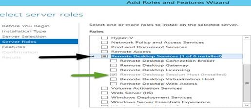
5. Click Next and complete the RDS server roles for RDSH Server Sessions enablement.
Create the Golden Image for Horizon Linked Clone Desktops
To create the Golden Image, complete the following steps:
1. Select ESXi host in Infrastructure cluster and create a virtual machine to use as the Golden Image with windows 10 OS. We used windows 10, 64 bit OS for our testing.
For the virtual machine, the following parameters were used:
Memory : 2048MB
Processor : 2vCPU
Hard Disk : 24 GB
Network Adapter : 1 VMXNET3 type attached to VDI1-VLAN port-group on Nexus 1000v for distributed port group capability
2. Attach the already downloaded Windows 10 LTSB Version Build 1607 to the virtual machine to complete the Windows 10 Master image installation.
3. Click Next.
4. Click Install now.
5. Accept the license terms.
6. Click Install windows.
Windows is installing.

The Windows installation is complete.

7. Customize the windows setup or use Express Settings.
8. Provide the User credentials for the windows VM created.

9. Reboot the Windows VM and install additional software as applicable.
VMware Horizon Agent Installation
To install the VMware Horizon Agent, complete the following steps:
1. Download VMware-viewagent-x86_64-7.0.3-4717913 version.
https://my.vmware.com/web/vmware/downloads
https://my.vmware.com/web/vmware/details?downloadGroup=VIEW-703-STD&productId=577&rPId=13974

2. Click the VMware Horizon Agent installer
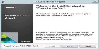
3. Click Next.
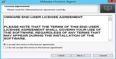
4. Accept the license agreement and click Next.

5. Select the default IPV4 and click Next.
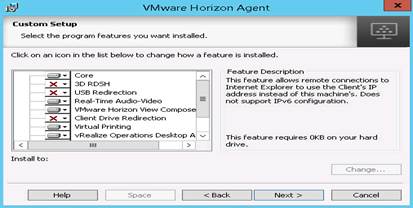
6. Select the features to install.

7. Click Install.
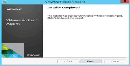
8. Click Finish to complete the Horizon Agent installation on the Master image.
![]() The same agent installation steps are applicable for the RDSH Server 2012 base Image you intend to use for RDS VMs.
The same agent installation steps are applicable for the RDSH Server 2012 base Image you intend to use for RDS VMs.
Prerequisites
To set the Scope Options on the DHCP server hosting the Horizon target machines (for example, RDSH and VDI virtual machines), complete the following steps:
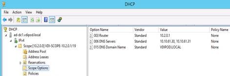
Provision Virtual Desktop Machines
To create VDI and RDS machines, complete the following steps:
1. Select the Master Target Device VM from the vSphere Client.
2. Right-click the VM and select Clone.
3. Name the cloned VM Desktop-Template.
4. Select the cluster and datastore where the first phase of provisioning will occur.
5. In case of RDSH VM, clone the RDS Master Image.
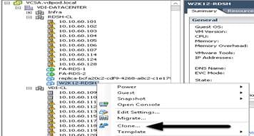
6. For Windows 10, follow the steps for cloning the Master Image for further deployment.
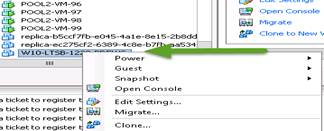
7. Change the network adapter for Windows 10 Golden Image template to N1KV port group to use the Cisco Nexus 1000V virtual port group.
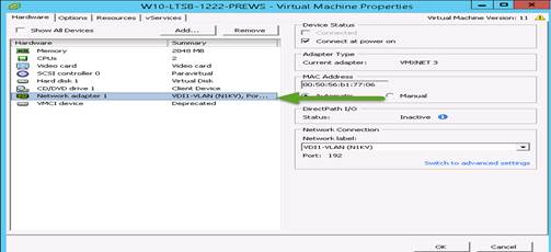
8. Change the memory to “Reserve all guest memory” (All locked).
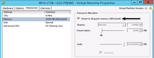
9. Convert the VM to a Template for additional steps.
10. When the template is ready, convert to VM and take a snapshot of the VM to deploy the VDI virtual machines from Horizon Administrator Console.
11. Right-click the Master Image and take a snapshot.
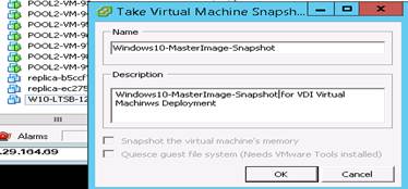
12. Provide a Name for the Master Image snapshot and click OK.
VMware Horizon Desktop Pool Creation
To create the VMware Horizon Desktop Pool, complete the following steps;
1. Login to Horizon 7 Administrator via a web browser; https://<IP Address or FQDN>/admin.
2. Login to VMware Horizon Connection Server Administrator to create the RDSH farm and RDSH pool or VDI Desktops Pools.
Create VDI Desktop Pool
1. Select Type of Desktop pool to be created.
![]() We created an Automated Desktop Pool.
We created an Automated Desktop Pool.
2. Click Next.

3. Select the pool type by clicking the Add button (for example, Automated pool or RDS pool).
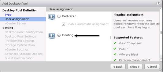
4. Select User Assignment for desktop pool. (We created Floating assigned.) Click Next.

5. Select vCenter Server and the type of Desktop deployment. (We created View Composer linked clones).
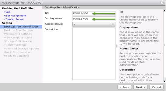
6. Provide the Pool ID and virtual display name
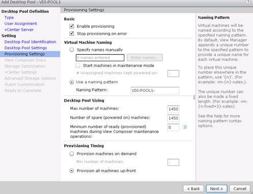
7. Provide the number of desktops to be provisioned (shown above POOL1-VDI, total of 1450 desktops).
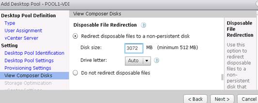
8. Select the option Redirect disposable files to non-persistent disk.
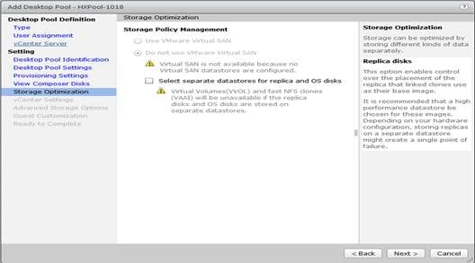
9. Select the required option for Storage Policy Management.
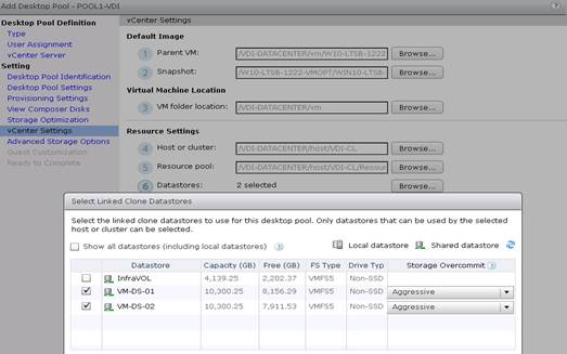
10. Provide the parent VM, snapshot and host/cluster info, datastore information for the virtual machines to create.
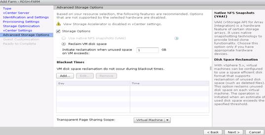
11. In Advanced Storage Options, select the View Storage Accelerator and reclaim disk space parameters as required.
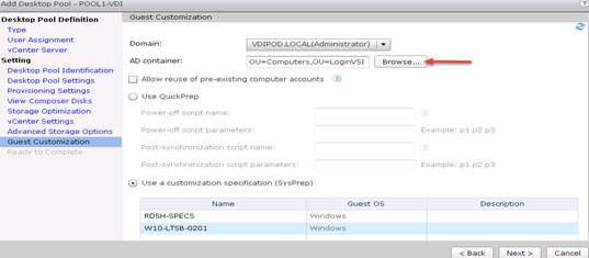
12. Select AD container for desktops to place in a Domain Controller computer location
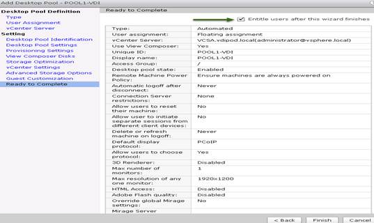
13. Review all the deployment specifications and click Finish to complete the deployment.
14. Select Entitle users after this wizard finishes, to enable desktop user group/ users to access this pool.
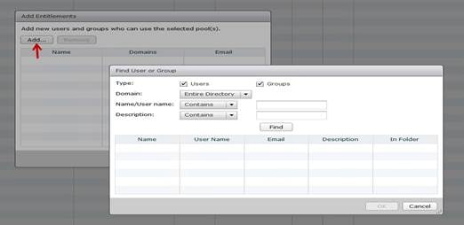
15. Add users group/ users to the pool:
- The computer container “LoginVSI“ created on the domain controller.
- <Domain Controller> Active Directory Users and Computers > vdipod.local > LoginVSI > Computers > VDI1-POOL-11,2…VDI1-POOL--1450
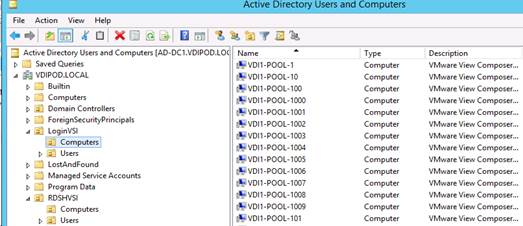
16. Login to the newly provisioned VDI1-POOL1 desktop machine.
Create RDSH Farm and Pool
It is recommended to create a RDSH Farm first with specifications set for RDS Server VMs and deploying a number of RDS servers required for users. To create the RDSH Farm and Pool, complete the following steps:
1. Select the FARM when creating the RDS Pool.
![]() You can entitle the user access at the RDS Pool level for RDS users/groups who can access the RDS VMs.
You can entitle the user access at the RDS Pool level for RDS users/groups who can access the RDS VMs.
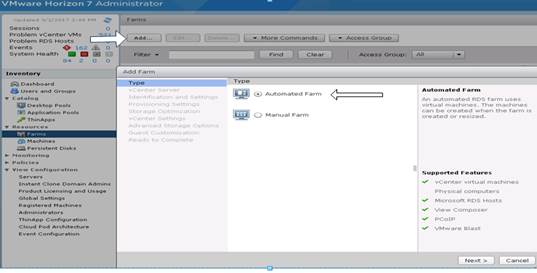
2. Click Add type of pool. We used automated pool in the study.
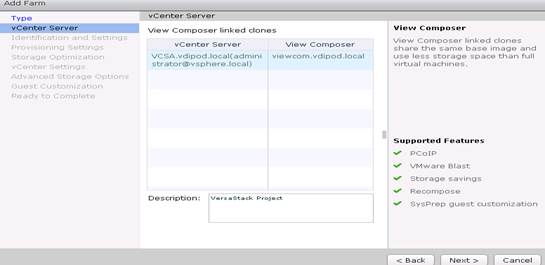
3. Click Next.
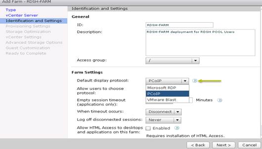
4. Provide ID and Description for RDS FARM. Select the Display Protocol which is required for users to connect to the RDS Sessions.
![]() For RDS Pool, we used Microsoft RDP protocol.
For RDS Pool, we used Microsoft RDP protocol.
5. Click Next.
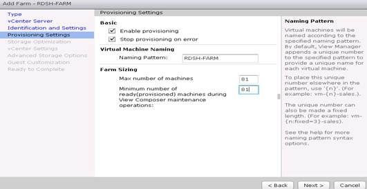
6. Provide the naming pattern for the RDS Desktops /VMs you want to create and the number of RDS VMs you want to create on the RDS host or RDS cluster. For example, 81 RDS server virtual machines created in this study.
7. Click Next.
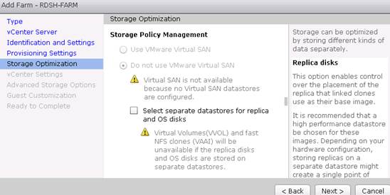
8. Complete the storage Optimization settings as required.
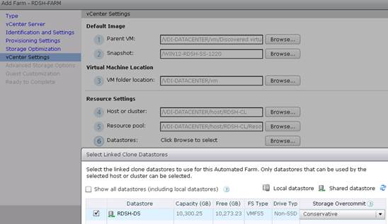
9. Provide all the information about vCenter settings with parent RDS master image, snapshot, Host /Cluster information, and Datastores for VMs to be stored.

10. Select the required advanced storage options.
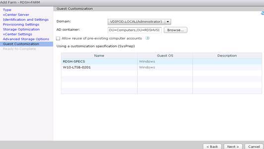
11. Select Active Directory Domain controller container (VMs to be stored on the separate Computer VM (RDSHVSI) container in the Domain Controller) intended for storing RDS VMs and select the sysprep customization specs for creating VMware Composer provisioned RDS VMs.
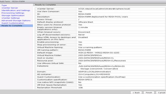
12. Review the RDS Farm automatic deployment specifications and click Finish to complete the RDS pool.
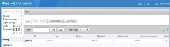
The RDS Farm is created in the Horizon admin console.
When the RDS FARM is created, you need to create a RDS pool to absorb the RDS VMS FARM into the Pool for further managing the RDS pool.
A Snapshot of the RDS VMs created in the AD container are selected in the deployment process.
· <Domain Controller> Active Directory Users and Computers > vdipod.local > RDSHVSI > Computers > RDSF-FARM1,2…RDSF-FARM81
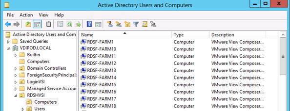
Create RDS Pool
1. Click Add type of pool section on the Horizon Administrator Console and the default choice is RDS Desktop Pool.
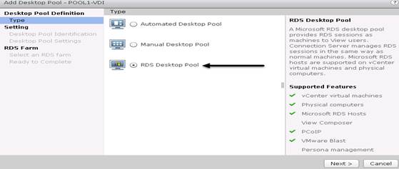
2. Provide ID and Display Name for the Pool. Click Next.

3. Leave default settings for the Desktop Pool Settings. Click Next.
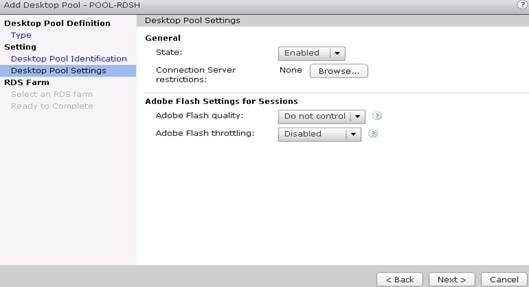
4. Select the RDS Farm. You have the option to create a farm or select the farm which is already created. We chose the option of selecting an RDS farm (FA-RDS) for this desktop pool. Click Next.
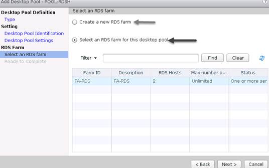
5. Click Ready to Complete and select Entitle users after this wizard finishes to give users/user group permission to access this RDS pool. Click Next.
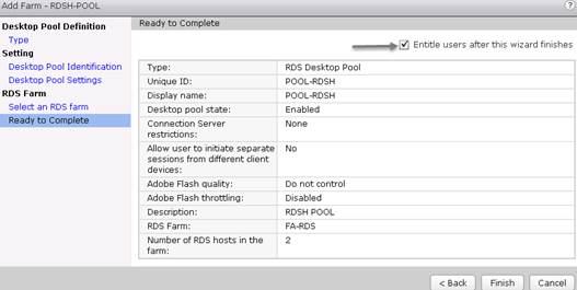
6. Select the users who can access this pool.

The RDS Pool is created on the Horizon Administrator console.
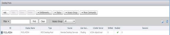
Configuring User Profile Management
Profile management provides an easy, reliable, and high-performance way to manage user personalization settings in virtualized or physical Windows environments. It requires minimal infrastructure and administration, and provides users with fast logons and logoffs. A Windows user profile is a collection of folders, files, registry settings, and configuration settings that define the environment for a user who logs on with a particular user account. These settings may be customizable by the user, depending on the administrative configuration. Examples of settings that can be customized are:
· Desktop settings such as wallpaper and screen saver
· Shortcuts and Start menu setting
· Internet Explorer Favorites and Home Page
· Microsoft Outlook signature
· Printers
Some user settings and data can be redirected by means of folder redirection. However, if folder redirection is not used these settings are stored within the user profile.
The first stage in planning a profile management deployment is to decide on a set of policy settings that together form a suitable configuration for your environment and users. The automatic configuration feature simplifies some of this decision-making for VMware Horizon desktop deployments. Screenshots of the User Profile Management interfaces that establish policies for this CVD’s RDS and VDI users (for testing purposes) are shown below. Basic profile management policy settings are documented here:
Single Server Testing
Figure 40 Cisco UCS B200 M4 Blade Server for Single Server Scalability VMware Horizon 7 Remote Desktop Server Hosted Sessions (RDSH) with Server 2012 R2
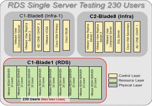
Figure 41 Cisco UCS B200 M4 Blade Server for Single Server Scalability VMware Horizon 7 VDI (Non-Persistent) with Windows 10 64bit OS
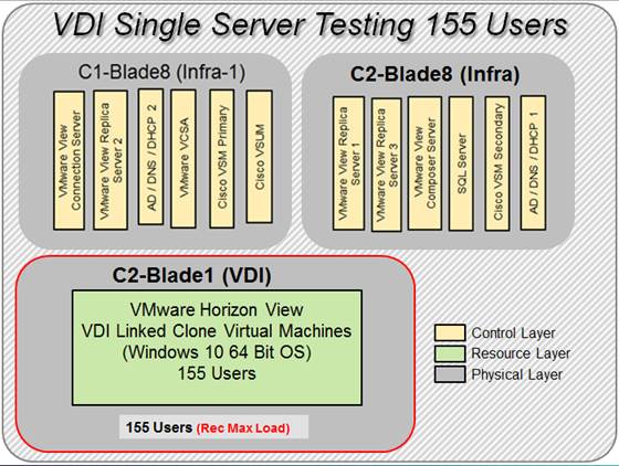
Hardware components:
· Cisco UCS 5108 Blade Server Chassis
· 2 Cisco UCS 6248 Fabric Interconnects
· 2 (Infrastructure Hosts) Cisco UCS B200 M4 Blade Servers (2 Intel Xeon processor E5-2660 v3 CPUs at 2.60 GHz, with 128GB of memory per blade server [16 GB x 8 DIMMs at 2400 MHz]) for infrastructure host blades
· Total number of VMware Horizon RDS server configured 9 and session 230
· 1 (one) Cisco UCS B200 M4 Blade Server (2 Intel Xeon processor E5-2680 v4 CPUs at 2.4 GHz, with 512GB of memory per blade server [32 GB x 16 DIMMs at 2400 MHz]) for workload host blade
or
· Total number of VMware Horizon Linked Clones VDI Virtual machines configured 155
· 1 (one) Cisco UCS B200 M4 Blade Server (2 Intel Xeon processor E5-2680 v4 CPUs at 2.4 GHz, with 512GB of memory per blade server [32 GB x 16DIMMs at 2400 MHz]) for workload host blade
· Cisco VIC 1340 CNA (1 per blade)
· 2 Cisco Nexus 9372PX Access Switches
· 2 Cisco MDS 9148S Fibre Channel Switches
· 1 IBM FlashSystem A9000 Storage with (12x1.2) 21.4 TB Raw disk capacity
Software components:
· Cisco UCS firmware 3.1(2b)
· VMware ESXi 6.0 Update 2 for host blades
· VMware Horizon RDS Hosted Shared Desktops or VMware Horizon 7 VDI Hosted Virtual Desktops
· VMware Horizon Composer Server 7
· Windows 2012 User Profile Server
· Microsoft SQL Server 2012
· Microsoft Windows 10 64 bit, 2vCPU, 2 GB RAM, 24 GB disk
· Microsoft Windows Server 2012 R2, 6vCPU, 24GB RAM, 40 GB disk
· Microsoft Office 2016
· Login VSI 4.1.5 Knowledge Worker Workload
Cisco UCS Configuration for Cluster Testing
This test case validates two workload clusters using VMware Horizon 7 with 2,100 RDS Hosted Server Sessions and 2900 VDI Linked Clone non- persistent virtual machines. Server N+1 fault tolerance is factored into this test scenario for each workload and infrastructure cluster.
Figure 42 RDS Cluster Test Configuration with Ten Blades
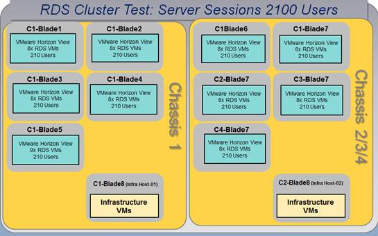
Figure 43 VDI Cluster Test with VDI Linked Clone Non-Persistent Cluster Test Configuration with Twenty Blades
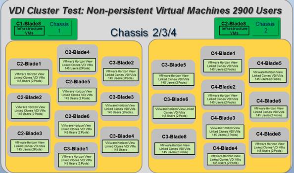
Hardware components:
· Cisco UCS 5108 Blade Server Chassis
· 2 Cisco UCS 6248 Fabric Interconnects
· 2 (Infrastructure Hosts) Cisco UCS B200 M4 Blade Servers (2 Intel Xeon processor E5-2660 v3 CPUs at 2.60 GHz, with 128GB of memory per blade server [16 GB x 8 DIMMs at 2400 MHz]) for infrastructure host blades
· 10 (Ten) Cisco UCS B200 M4 Blade Server (2 Intel Xeon processor E5-2680 v4 CPUs at 2.4 GHz, with 512GB of memory per blade server [32 GB x 16 DIMMs at 2400 MHz]) for workload host blades
· Total of 81 VMware Horizon RDS Server VMs configured on 10 Hosts RDSH Cluster
· Total number of RDS Hosted Server Sessions 2100
or
· 20 (Twenty) Cisco UCS B200 M4 Blade Server (2 Intel Xeon processor E5-2680 v4 CPUs at 2.4 GHz, with 512GB of memory per blade server [32 GB x 16 DIMMs at 2400 MHz]) for workload host blade
· Total no of VDI Virtual Machines Configured 2900 on 2 VMware Horizon Linked Clone (2 VDI Pools, 1450 desktops each pool) pools.
· Cisco VIC 1340 CNA (1 per blade)
· 2 Cisco Nexus 9372PX Access Switches
· 2 Cisco MDS 9148S Fibre Channel Switches
· 1 IBM FlashSystem A9000 Storage with (12x1.2) 21.4 TB Raw disk capacity
Software components:
· Cisco UCS firmware 3.1(2b)
· VMware ESXi 6.0 Update 2 for host blades
· VMware Horizon RDS Hosted Shared Desktops or VMware Horizon 7 VDI Hosted Virtual Desktops
· VMware Horizon Composer Server 7
· Windows 2012 User Profile Server
· Microsoft SQL Server 2012
· Microsoft Windows 10 64 bit, 2vCPU, 2 GB RAM, 24 GB disk
· Microsoft Windows Server 2012 R2, 6vCPU, 24GB RAM, 40 GB disk
· Microsoft Office 2016
· Login VSI 4.1.5 Knowledge Worker Workload
Cisco UCS Configuration for Full Scale Testing
This test case validates thirty blades mixed workloads using VMware Horizon 7 with 2,100 RDS Hosted sessions and 2,900 VDI non-persistent virtual desktops for a total sum of 5,000 users. Server N+1 fault tolerance is factored into this solution for each workload and infrastructure cluster.
Figure 44 Full Scale Test Configuration with Thirty Blades
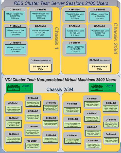
Hardware components:
· Cisco UCS 5108 Blade Server Chassis
· 2 Cisco UCS 6248 Fabric Interconnects
· 2 (Infrastructure Hosts) Cisco UCS B200 M4 Blade Servers (2 Intel Xeon processor E5-2660 v3 CPUs at 2.60 GHz, with 128GB of memory per blade server [16 GB x 8 DIMMs at 2400 MHz]) for infrastructure host blades
· 10 (Ten) Cisco UCS B200 M4 Blade Server (2 Intel Xeon processor E5-2680 v4 CPUs at 2.4 GHz, with 512GB of memory per blade server [32 GB x 16 DIMMs at 2400 MHz]) for workload host blades
· Total of 81 VMware Horizon RDS Server VMs configured on 10 Hosts RDSH Cluster
· Total no of RDS Hosted Server Sessions 2100
AND
· 20 (Twenty) Cisco UCS B200 M4 Blade Server (2 Intel Xeon processor E5-2680 v4 CPUs at 2.4 GHz, with 512GB of memory per blade server [32 GB x 16 DIMMs at 2400 MHz]) for workload host blade
· Total number of VDI Virtual Machines Configured 2900 on 2 VMware Horizon Linked Clone (2 VDI Pools, 1450 each pool) pools.
· Cisco VIC 1340 CNA (1 per blade)
· 2 Cisco Nexus 9372PX Access Switches
· 2 Cisco MDS 9148S Fibre Channel Switches
· 1 IBM FlashSystem A9000 Storage with (12x 1.2) 21.4 TB Raw disk capacity
Software components:
· Cisco UCS firmware 3.1(2b)
· VMware ESXi 6.0 Update 2 for host blades
· VMware Horizon RDS Hosted Shared Desktops or VMware Horizon 7 VDI Hosted Virtual Desktops
· VMware Horizon Composer Server 7
· Windows 2012 User Profile Server
· Microsoft SQL Server 2012
· Microsoft Windows 10 64 bit, 2vCPU, 2 GB RAM, 24 GB disk
· Microsoft Windows Server 2012 R2, 6vCPU, 24GB RAM, 40 GB disk
· Microsoft Office 2016
· Login VSI 4.1.5 Knowledge Worker Workload
All validation testing was conducted on-site within the Cisco labs in San Jose, California.
The testing results focused on the entire process of the virtual desktop lifecycle by capturing metrics during the desktop boot-up, user logon and virtual desktop acquisition (also referred to as ramp-up,) user workload execution (also referred to as steady state), and user logoff for the RDSH Servers Session under test.
Test metrics were gathered from the virtual desktop, storage, and load generation software to assess the overall success of an individual test cycle. Each test cycle was not considered passing unless all of the planned test users completed the ramp-up and steady state phases (described below) and unless all metrics were within the permissible thresholds as noted as success criteria.
Three successfully completed test cycles were conducted for each hardware configuration and results were found to be relatively consistent from one test to the next.
You can obtain additional information and a free test license from http://www.loginvsi.com
Testing Procedure
The following protocol was used for each test cycle in this study to insure consistent results.
Pre-Test Setup for Single and Multi-Blade Testing
All machines were shut down utilizing the VMware Horizon 7 Administrator Console.
All Launchers for the test were shut down. They were then restarted in groups of 10 each minute until the required number of launchers was running with the Login VSI Agent at a “waiting for test to start” state.
Test Run Protocol
To simulate severe, real-world environments, Cisco requires the log-on and start-work sequence, known as Ramp Up, to complete in 48 minutes. Additionally, we require all sessions started, whether 60 single server users or 900 full scale test users, to become active within two minutes after the last session is launched.
In addition, Cisco requires that the Login VSI Benchmark method is used for all single server and scale testing. This assures that our tests represent real-world scenarios. For each of the three consecutive runs on single server tests, the same process was followed. Complete the following steps:
1. Time 0:00:00 Start PerfMon Logging on the following systems:
· Infrastructure and VDI Host Blade servers used in test run
· All Infrastructure VMs used in test run (AD, SQL, Horizon Connection brokers, Horizon Composer, etc.)
2. Time 0:00:10 Start Storage Partner Performance Logging on Storage System.
3. Time 0:05: Boot RDS Machines using VMware Horizon 7 Administrator Console.
4. Time 0:06 First machines boot.
5. Time 0:35 Single Server or Scale target number of RDS Servers registered on XD.
![]() No more than 60 Minutes of rest time is allowed after the last desktop is registered and available on VMware Horizon 7 Administrator Console dashboard. Typically a 20-30 minute rest period for Windows 10 desktops and 10 minutes for RDS VMs is sufficient.
No more than 60 Minutes of rest time is allowed after the last desktop is registered and available on VMware Horizon 7 Administrator Console dashboard. Typically a 20-30 minute rest period for Windows 10 desktops and 10 minutes for RDS VMs is sufficient.
6. Time 1:35 Start Login VSI 4.1.5 Office Worker Benchmark Mode Test, setting auto-logoff time at 900 seconds, with Single Server or Scale target number of desktop VMs utilizing sufficient number of Launchers (at 20-25 sessions/Launcher).
7. Time 2:23 Single Server or Scale target number of desktop VMs desktops launched (48 minute benchmark launch rate).
8. Time 2:25 All launched sessions must become active.
![]() All sessions launched must become active for a valid test run within this window.
All sessions launched must become active for a valid test run within this window.
9. Time 2:40 Login VSI Test Ends (based on Auto Logoff 900 Second period designated above).
10. Time 2:55 All active sessions logged off.
![]() All sessions launched and active must be logged off for a valid test run. The VMware Horizon 7 Administrator Dashboard must show that all desktops have been returned to the registered/available state as evidence of this condition being met.
All sessions launched and active must be logged off for a valid test run. The VMware Horizon 7 Administrator Dashboard must show that all desktops have been returned to the registered/available state as evidence of this condition being met.
11. Time 2:57 All logging terminated; Test complete.
12. Time 3:15 Copy all log files off to archive; Set virtual desktops to maintenance mode through broker; Shutdown all Windows 10 machines.
13. Time 3:30 Reboot all hypervisors.
14. Time 3:45 Ready for new test sequence.
Success Criteria
Our “pass” criteria for this testing follows:
Cisco will run tests at a session count level that effectively utilizes the blade capacity measured by CPU utilization, memory utilization, storage utilization, and network utilization. We will use Login VSI to launch version 4.1.5 Knowledge Worker workloads. The number of launched sessions must equal active sessions within two minutes of the last session launched in a test as observed on the VSI Management console.
The VMware Horizon Administrator Console or Horizon Connection Server Console must be monitored throughout the steady state to make sure of the following:
· All running sessions report In Use throughout the steady state
· No sessions move to unregistered, unavailable or available state at any time during steady state
Within 20 minutes of the end of the test, all sessions on all launchers must have logged out automatically and the Login VSI Agent must have shut down.
Cisco requires three consecutive runs with results within +/-1% variability to pass the Cisco Validated Design performance criteria. For white papers written by partners, two consecutive runs within +/-1% variability are accepted. (All test data from partner run testing must be supplied along with proposed white paper.)
We will publish Cisco Validated Designs with our recommended workload following the process above and will note that we did not reach a VSImax dynamic in our testing VersaStack with Cisco UCS B200 M4 and VMware Horizon 7 on VMware ESXi 6.0 Update 2 Test Results.
The purpose of this testing is to provide the data needed to validate VMware Horizon Remote Desktop Session Hosted (RDSH) server sessions and VMware Horizon Virtual Desktop (VDI) models with VMware Horizon Composer 7 using ESXi, vCenter to virtualize Microsoft Windows 10 desktops and Microsoft Windows Server 2012 R2 sessions on Cisco UCS B200 M4 Blade Servers using a IBM FlashSystem A9000 storage system.
The information contained in this section provides data points that a customer may reference in designing their own implementations. These validation results are an example of what is possible under the specific environment conditions outlined here, and do not represent the full characterization of VMware Horizon products with VMware vSphere.
Three test sequences, each containing three consecutive test runs generating the same result, were performed to establish single blade performance and multi-blade, linear scalability.
VSImax 4.1.x Description
The philosophy behind Login VSI is different to conventional benchmarks. In general, most system benchmarks are steady state benchmarks. These benchmarks execute one or multiple processes, and the measured execution time is the outcome of the test. Simply put: the faster the execution time or the bigger the throughput, the faster the system is according to the benchmark.
Login VSI is different in approach. Login VSI is not primarily designed to be a steady state benchmark (however, if needed, Login VSI can act like one). Login VSI was designed to perform benchmarks for SBC or VDI workloads through system saturation. Login VSI loads the system with simulated user workloads using well known desktop applications like Microsoft Office, Internet Explorer and Adobe PDF reader. By gradually increasing the amount of simulated users, the system will eventually be saturated. When the system is saturated, the response time of the applications will increase significantly. This latency in application response times show a clear indication whether the system is (close to being) overloaded. As a result, by nearly overloading a system it is possible to find out what its true maximum user capacity is.
After a test is performed, the response times can be analyzed to calculate the maximum active session/desktop capacity. Within Login VSI this is calculated as VSImax. When the system is coming closer to its saturation point, response times will rise. When reviewing the average response time it will be clear the response times escalate at saturation point.
This VSImax is the “Virtual Session Index (VSI).” With Virtual Desktop Infrastructure (VDI) and Terminal Services (RDS) workloads this is valid and useful information. This index simplifies comparisons and makes it possible to understand the true impact of configuration changes on hypervisor host or guest level.
Server-Side Response Time Measurements
It is important to understand why specific Login VSI design choices have been made. An important design choice is to execute the workload directly on the target system within the session instead of using remote sessions. The scripts simulating the workloads are performed by an engine that executes workload scripts on every target system, and are initiated at logon within the simulated user’s desktop session context.
An alternative to the Login VSI method would be to generate user actions client side through the remoting protocol. These methods are always specific to a product and vendor dependent. More importantly, some protocols simply do not have a method to script user actions client side.
For Login VSI the choice has been made to execute the scripts completely server side. This is the only practical and platform independent solution, for a benchmark like Login VSI.
Calculating VSImax v4.1.x
The simulated desktop workload is scripted in a 48 minute loop when a simulated Login VSI user is logged on, performing generic Office worker activities. After the loop is finished it will restart automatically. Within each loop the response times of sixteen specific operations are measured in a regular interval: sixteen times in within each loop. The response times of these five operations are used to determine VSImax.
The five operations from which the response times are measured are:
· Notepad File Open (NFO)
Loading and initiating VSINotepad.exe and opening the openfile dialog. This operation is handled by the OS and by the VSINotepad.exe itself through execution. This operation seems almost instant from an end-user’s point of view.
· Notepad Start Load (NSLD)
Loading and initiating VSINotepad.exe and opening a file. This operation is also handled by the OS and by the VSINotepad.exe itself through execution. This operation seems almost instant from an end-user’s point of view.
· Zip High Compression (ZHC)
This action copy's a random file and compresses it (with 7zip) with high compression enabled. The compression will very briefly spike CPU and disk IO.
· Zip Low Compression (ZLC)
This action copy's a random file and compresses it (with 7zip) with low compression enabled. The compression will very briefly disk IO and creates some load on the CPU.
· CPU
Calculates a large array of random data and spikes the CPU for a short period of time.
These measured operations within Login VSI do hit considerably different subsystems such as CPU (user and kernel), Memory, Disk, the OS in general, the application itself, print, GDI, etc. These operations are specifically short by nature. When such operations become consistently long: the system is saturated because of excessive queuing on any kind of resource. As a result, the average response times will then escalate. This effect is clearly visible to end-users. If such operations consistently consume multiple seconds the user will regard the system as slow and unresponsive.
Figure 45 Sample of a VSI Max Response Time Graph, representing a Normal Test
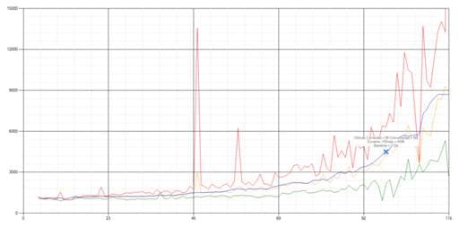
Figure 46 Sample of a VSI Test Response Time Graph (where there was a clear performance issue)
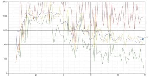
When the test is finished, VSImax can be calculated. When the system is not saturated, and it could complete the full test without exceeding the average response time latency threshold, VSImax is not reached and the amount of sessions ran successfully.
The response times are very different per measurement type, for instance Zip with compression can be around 2800 ms, while the Zip action without compression can only take 75ms. These response time of these actions are weighted before they are added to the total. This ensures that each activity has an equal impact on the total response time.
In comparison to previous VSImax models, this weighting much better represent system performance. All actions have very similar weight in the VSImax total. The following weighting of the response times are applied.
The following actions are part of the VSImax v4.1 calculation and are weighted as follows (US notation):
· Notepad File Open (NFO): 0.75
· Notepad Start Load (NSLD): 0.2
· Zip High Compression (ZHC): 0.125
· Zip Low Compression (ZLC): 0.2
· CPU: 0.75
This weighting is applied on the baseline and normal Login VSI response times.
With the introduction of Login VSI 4.1 we also created a new method to calculate the basephase of an environment. With the new workloads (Taskworker, Powerworker, etc.) enabling 'basephase' for a more reliable baseline has become obsolete. The calculation is explained below. In total 15 lowest VSI response time samples are taken from the entire test, the lowest 2 samples are removed and the 13 remaining samples are averaged. The result is the Baseline. In short:
· Take the lowest 15 samples of the complete test
· From those 15 samples remove the lowest 2
· Average the 13 results that are left is the baseline
The VSImax average response time in Login VSI 4.1.x is calculated on the amount of active users that are logged on the system.
Always a 5 Login VSI response time samples are averaged + 40 percent of the amount of “active” sessions. For example, if the active sessions is 60, then latest 5 + 24 (=40 percent of 60) = 31 response time measurement are used for the average calculation.
To remove noise (accidental spikes) from the calculation, the top 5 percent and bottom 5 percent of the VSI response time samples are removed from the average calculation, with a minimum of 1 top and 1 bottom sample. As a result, with 60 active users, the last 31 VSI response time sample are taken. From those 31 samples the top 2 samples are removed and lowest 2 results are removed (5 percent of 31 = 1.55, rounded to 2). At 60 users the average is then calculated over the 27 remaining results.
VSImax v4.1.x is reached when the VSIbase + a 1000 ms latency threshold is not reached by the average VSI response time result. Depending on the tested system, VSImax response time can grow 2 - 3x the baseline average. In end-user computing, a 3x increase in response time in comparison to the baseline is typically regarded as the maximum performance degradation to be considered acceptable.
In VSImax v4.1.x this latency threshold is fixed to 1000ms, this allows better and fairer comparisons between two different systems, especially when they have different baseline results. Ultimately, in VSImax v4.1.x, the performance of the system is not decided by the total average response time, but by the latency is has under load. For all systems, this is now 1000ms (weighted).
The threshold for the total response time is: average weighted baseline response time + 1000ms.
When the system has a weighted baseline response time average of 1500ms, the maximum average response time may not be greater than 2500ms (1500+1000). If the average baseline is 3000 the maximum average response time may not be greater than 4000ms (3000+1000).
When the threshold is not exceeded by the average VSI response time during the test, VSImax is not hit and the amount of sessions ran successfully. This approach is fundamentally different in comparison to previous VSImax methods, as it was always required to saturate the system beyond VSImax threshold.
Lastly, VSImax v4.1.x is now always reported with the average baseline VSI response time result. For example: “The VSImax v4.1 was 125 with a baseline of 1526ms”. This helps considerably in the comparison of systems and gives a more complete understanding of the system. The baseline performance helps to understand the best performance the system can give to an individual user. VSImax indicates what the total user capacity is for the system. These two are not automatically connected and related.
When a server with a very fast dual core CPU, running at 3.6 GHZ, is compared to a 10 core CPU, running at 2,26 GHZ, the dual core machine will give and individual user better performance than the 10 core machine. This is indicated by the baseline VSI response time. The lower this score is, the better performance an individual user can expect.
However, the server with the slower 10 core CPU will easily have a larger capacity than the faster dual core system. This is indicated by VSImax v4.1.x, and the higher VSImax is, the larger overall user capacity can be expected.
With Login VSI 4.1.x a new VSImax method is introduced: VSImax v4.1. This methodology gives much better insight in system performance and scales to extremely large systems.
Single-Server Recommended Maximum Workload
For both the VMware Horizon 7 RDS Hosted Virtual Desktops and VDI virtual machines use cases, a recommended maximum workload was determined that was based on both Login VSI Medium workload with flash end user experience measures and blade server operating parameters.
This recommended maximum workload approach allows you to determine the server N+1 fault tolerance load the blade can successfully support in the event of a server outage for maintenance or upgrade.
Our recommendation is that the Login VSI Average Response and VSI Index Average should not exceed the Baseline plus 2100 milliseconds to insure that end user experience is outstanding. Additionally, during steady state, the processor utilization should average no more than 90-95%. (Memory should never be oversubscribed for Desktop Virtualization workloads.)
Callouts have been added throughout the data charts to indicate each phase of testing.
| Test Phase |
Description |
| Boot |
Start all RDS and VDI virtual machines at the same time |
| Logon |
The Login VSI phase of test is where sessions are launched and start executing the workload over a 48 minutes duration |
| Steady state |
The steady state phase is where all users are logged in and performing various workload tasks such as using Microsoft Office, Web browsing, PDF printing, playing videos, and compressing files (typically for 15 minute duration) |
| Logoff |
Sessions finish executing the Login VSI workload and logoff |
Single-Server Recommended Maximum Workload Testing
This section shows the key performance metrics that were captured on the Cisco UCS host blades during the single server testing to determine the Recommended Maximum Workload per host server. The single server testing comprised of two tests: 230 RDS Hosted sessions and 155 VMware Horizon pooled Non-Persistent VDI desktops.
Single-Server Recommended Maximum Workload for RDS Hosted Server Sessions: 230 Users
Figure 47 Single Server Recommended Maximum Workload for RDS with 230 Users
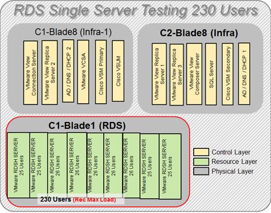
The recommended maximum workload for a B200 M4 blade server with dual E5-2680 v4 processors and 256GB of RAM is 230 Server 2012 R2 Remote Desktop Server Hosted Session Desktops. Each dedicated blade server ran 9 Server 2012 R2 Virtual Machines. Each virtual server was configured with 6 vCPUs and 24GB RAM.
Figure 48 Single Server | VMware Horizon 7 RDS Hosted Sessions | VSI Score
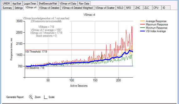
Performance data for the server running the workload is shown below:
Figure 49 Single Server | VMware Horizon 7 RDSH processor | Host CPU Utilization

Figure 50 Single Server | VMware Horizon 7 RDSH | Host Memory Utilization
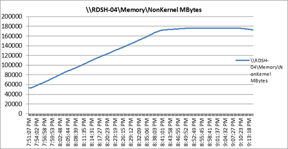
Figure 51 Single Server | VMware Horizon 7 RDSH | Host Network Utilization
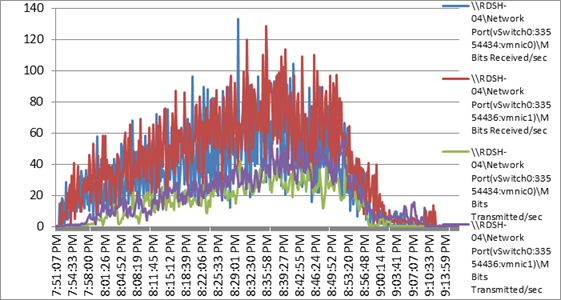
Figure 52 Single Server | VMware Horizon 7 RDSH processor (Total%) Processor Time
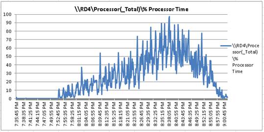
Figure 53 Single Server | VMware Horizon 7 RDSH processor (Total%) User Time
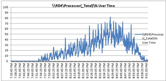
Single-Server Recommended Maximum Workload for VDI Non-Persistent with 155 Users
Figure 54 Single Server Recommended Maximum Workload for VDI Non-Persistent with 155 Users
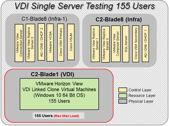
The recommended maximum workload for a Cisco UCS B200 M4 blade server with dual E5-2680 v4 processors and 512GB of RAM is 155 Windows 10 64-bit virtual machines with 2 vCPU and 2GB RAM. The Login VSI and blade performance data is shown below.
Figure 55 Single Server | VMware Horizon 7 VDI-Non Persistent | VSI Score
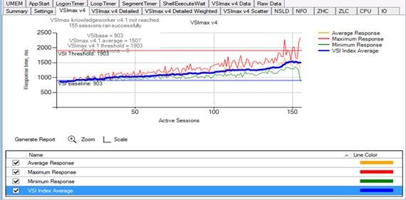
Performance data for the server running the workload is shown below:
Figure 56 Single Server | VMware Horizon VDI Non–Persistent Desktops | Host CPU Utilization

Figure 57 Single Server | VMware Horizon VDI Non –Persistent Desktops | Host Memory Utilization
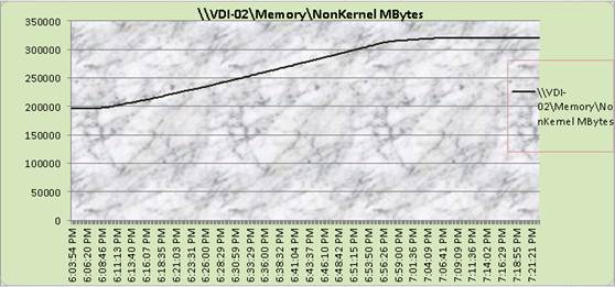
Figure 58 Single Server | VMware Horizon VDI non –persistent desktops | Host Network Utilization
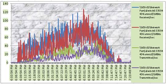
Cluster Workload Testing with 2100 RDS Users
This section shows the key performance metrics that were captured on the Cisco UCS, IBM FlashSystem A9000 and RDS workload VMs during the RDSH Sessions testing. The cluster testing with comprised of 2100 RDS Hosted sessions using 10 Cisco UCS B200 M4 workload blades.
Figure 59 RDS Cluster Testing with 2100 Users
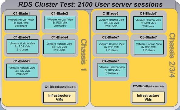
The workload for the test is 2100 RDS users. To achieve the target, sessions were launched against the single RDS cluster only. As per the Cisco Test Protocol for VDI solutions, all sessions were launched within 48 minutes (using the official Knowledge Worker Workload in VSI Benchmark Mode) and all launched sessions became active within two minutes subsequent to the last logged in session.
The configured system efficiently and effectively delivered the following results:
Figure 60 RDSH Cluster | 2100 RDS Users | VMware Horizon RDSH VSI Score

Figure 61 RDSH Cluster | 2100 RDS Users | Workload Host | Host CPU Utilization

Figure 62 RDSH Cluster | 2100 RDS Users | Workload Host | Host Memory Utilization
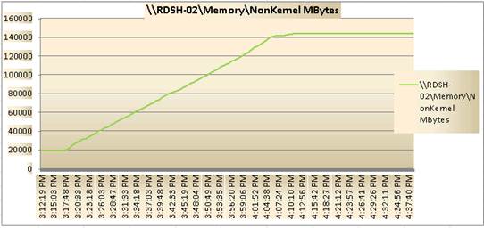
Figure 63 RDSH Cluster | 2100 RDS Users | RDS Host | Host Network Utilization
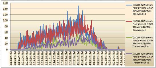
Figure 64 Cluster | 2100 RDS Users | RDS Host | Host Fibre Channel Network Utilization
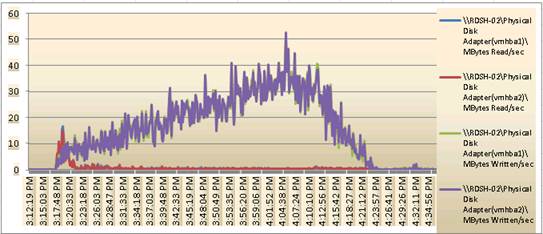
Performance Data from One RDSH Server: 2100 Users RDSH Sessions Cluster Testing
Figure 65 RDSH Server Processor (Total%) Time
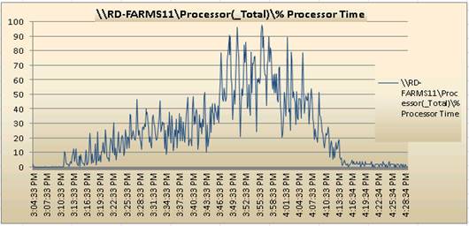
Figure 66 RDSH Server User (Total%) Time

Cluster Workload Testing with 2900 Non-Persistent VDI Desktop Users
This section shows the key performance metrics that were captured on the Cisco UCS, IBM FlashSystem A9000 storage, and Infrastructure VMs during the persistent desktop testing. The cluster testing with comprised of 2900 VDI Persistent desktop sessions using 20 workload blades.
Figure 67 VMware Horizon VDI Non-Persistent Cluster Testing with 2900 Users

The workload for the test is 2900 non-persistent desktop users. To achieve the target, sessions were launched against the single persistent cluster only. As per the Cisco Test Protocol for VDI solutions, all sessions were launched within 48 minutes (using the official Knowledge Worker Workload in VSI Benchmark Mode) and all launched sessions became active within two minutes subsequent to the last logged in session.
The configured system efficiently and effectively delivered the following results:
Figure 68 VDI Cluster | VMware Horizon 2900 VDI Non-Persistent Users | VSI Score
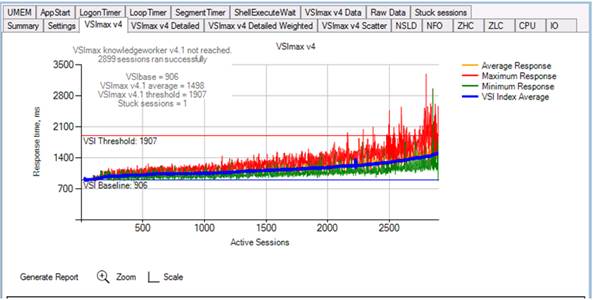
Figure 69 VDI Cluster | VDI Cluster | 2900 VDI Non-Persistent Users | VDI Host | Host CPU Utilization
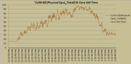
Figure 70 VDI Cluster | VDI Cluster | 2900 VDI Non-Persistent Users | VDI Host | Host Memory Utilization
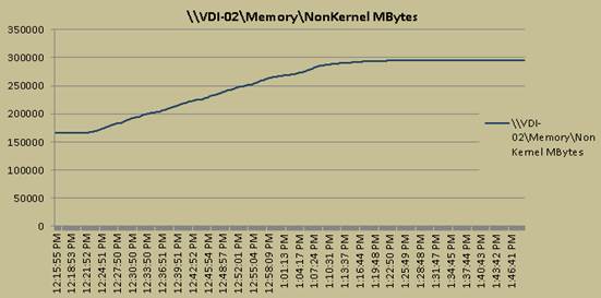
Figure 71 VDI Cluster | 2900 VDI non-Persistent Users | VDI Host | Host Network Utilization

Figure 72 VDI Cluster | 2900 VDI-Non Persistent Users | VDI Host | Host Fibre Channel Network Utilization
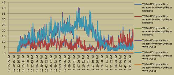
Full Scale Mixed Workload Testing with 5000 Users
This section shows the key performance metrics that were captured on the Cisco UCS, IBM FlashSystem A9000 storage, RDSH VMs and VDI non –persistent performance monitoring during the full-scale testing. The full-scale testing with 5000 users comprised of: 2100 RDS Hosted Server Sessions using 10 Cisco UCS B200 M4 blades, 2900 VDI Non-Persistent Linked clones virtual machines using 20 Cisco UCS B200 M4 blades.
Figure 73 Full Scale Mixed Test with 5000 Users
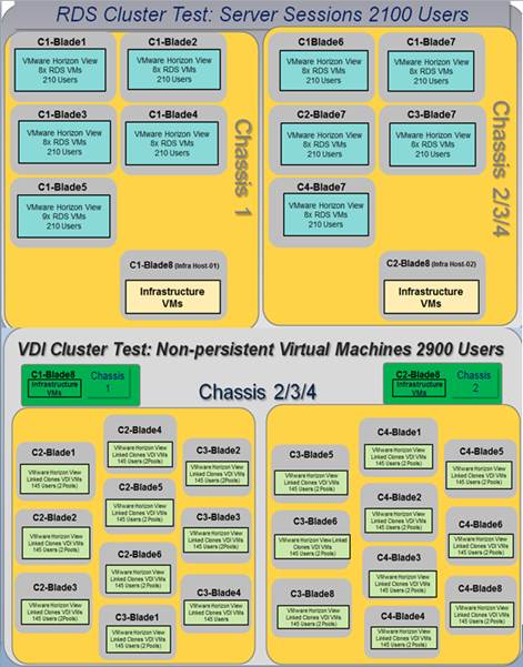
The combined mixed workload for the solution is 5000 users. To achieve the target, sessions were launched against all workload clusters concurrently. As per the Cisco Test Protocol for VDI solutions, all sessions were launched within 48 minutes (using the official Knowledge Worker Workload in VSI Benchmark Mode) and all launched sessions became active within two minutes subsequent to the last logged in session.
The configured system efficiently and effectively delivered the following results:
Figure 74 Full Scale | 5000 Mixed Users | VSI Score
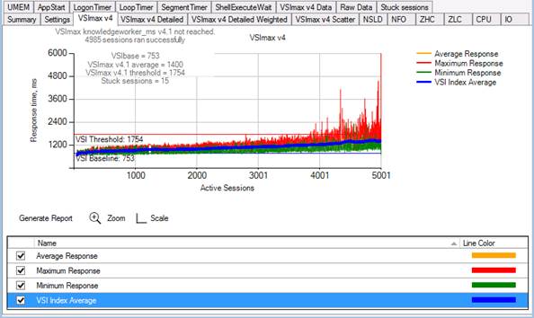
Figure 75 Full Scale | 5000 Mixed Users RDSH Server Host | Host CPU Utilization
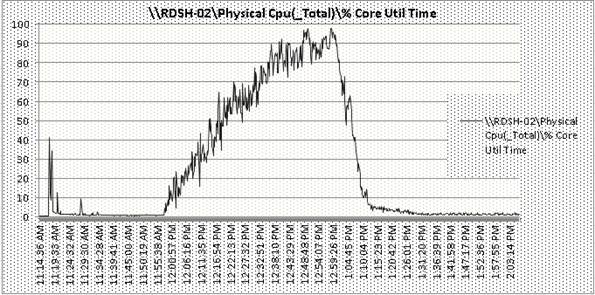
Figure 76 Full Scale | 5000 Mixed Users RDSH Server Host | Host Memory Utilization
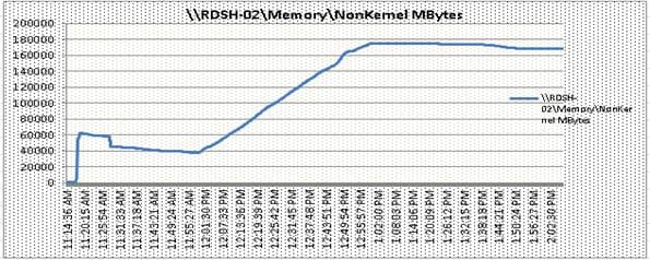
Figure 77 Full Scale | 5000 Mixed Users RDSH Server Host | Host CPU Network Utilization
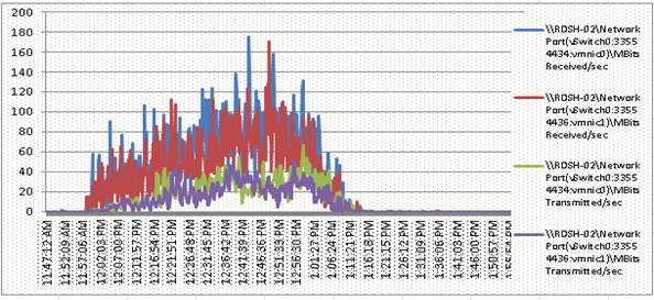
Figure 78 Full Scale | 5000 Mixed Users RDSH Server Host | Host vHBA Adapter Utilization
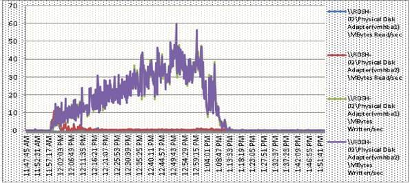
RDSH Server Performance Monitor Data for One Sample RDSH Server: 5000 Users Mixed Scale Testing
Figure 79 RDSH Server Processor (Total%) Time
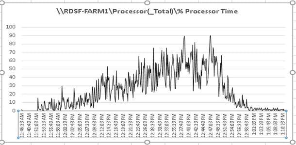
Figure 80 RDSH Server User (Total%) Time
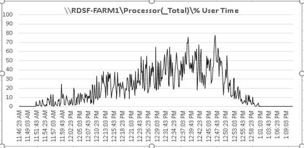
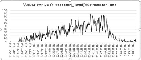
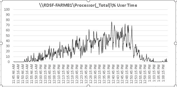
Figure 81 Full Scale | 5000 Mixed Users | VDI Host | Host CPU Utilization

Figure 82 Full Scale | 5000 Mixed Users | VDI Host | Host Memory Utilization
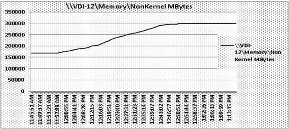
Figure 83 Full Scale | 5000 Mixed Users | VDI Host | Host Network Utilization
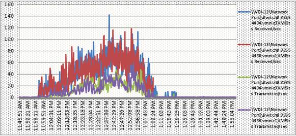
Figure 84 Full Scale | 5000 Mixed Users | VDI Host | Host Fibre Channel Network Utilization
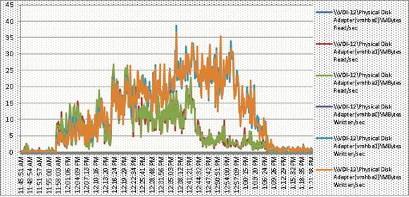
Storage Graphs
Figure 85 IBM A9000 5000 Users Mixed Workload Scale Test | Read/Write Latency
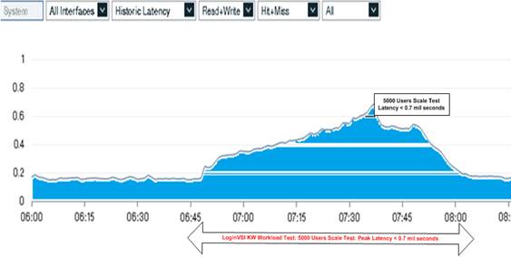
Figure 86 IBM A9000 5000 Users Mixed Workload Scale Test | Bandwidth | Transmitted /Received
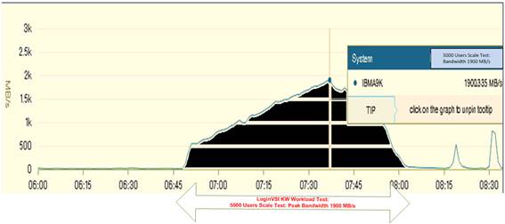
Figure 87 IBM A9000 5000 Users Mixed Workload FlashSystem Read/Write IOPS
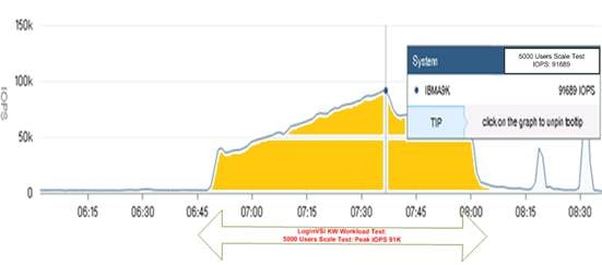
IBM FlashSystem A9000 Storage Detailed Test Results for Cluster Scalability Test
The following section highlights and provides analysis of the IBM FlashSystem A9000 storage performance results for each of the cluster test cases identified earlier in this document. Specifically, we will show and discuss results for the following test scenarios:
· 2100 Windows Server 2012 RDS Hosted VMware Horizon Sessions
· 2900 Windows 10 x64 Non-Persistent VMware Horizon Sessions
From a storage perspective, it is critical to maintain a latency of less than a millisecond in order to guarantee a good end-user experience no matter what amount of IOPS and bandwidth are being driven. As we will see, IBM FlashSystem A9000 storage delivers that essential minimum level of latency despite driving a substantial amount of IOPs and bandwidth for the thousands of desktops hosted on the IBM FlashSystem A9000 storage.
The upcoming screenshots of the IBM FlashSystem A9000 storage test data for all 3 use case scenarios with the information about IOPS, Bandwidth and Latency at the leak of each use case test. In all 3 use cases (cluster level testing with RDSH, VDI and with Mixed workload use case, the criteria followed prior to launching LoginVSI workload test same.
Followed by this stage is a forty minute window for all RDSH and VDI VMs to settle and then we begin the 2880 second Login VSI simulation phase when all sessions are ramping up and logging in.
IBM FlashSystem A9000 Storage Test Results for 2100 RDS Windows 2012 Sessions
Using Login VSI as the workload generator in Benchmark mode with the Knowledge Worker user type and with VMware Remote Desktop Session Hosts (RDSH) Server Sessions as the VDI delivery mechanism, our first highlighted cluster test shows that the FlashSystem can easily handle this workload with exceptional end-user experience confirmed from Login VSI.
The first IBM FlashSystem A9000 storage GUI screenshot shows the FlashSystem performance during the 2100 RDSH sessions running on top of 81 Windows 2012R2 servers. As with all scenarios, there were three separate 2100 RDSH simulation runs completed in total, all with very similar results. As you can see in the below chart from one of these simulations - we maintained latency of less than or close to one millisecond for both read and write operations throughout this entire run. This resulted in a confirmed outstanding end-user experience for the simulated VMware RDSH users independently verified by Login VSI. It has been observed during this component of the testing with observed peak total values 2.45K IOPS and 684.014 MB/s. The latency is less than 0.45 mil sec which is a very good end user experience.
2100 RDSH Cluster Test: Storage Charts
Figure 88 IBM A9000 2100 Users RDSH Cluster Test | FlashSystem Read/Write IOPS
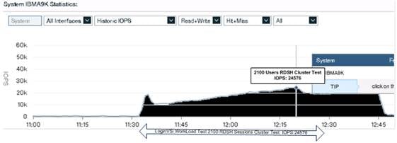
Figure 89 IBM A9000 2100 Users RDSH Cluster Test |FlashSystem | Bandwidth | Recevied Transmitted
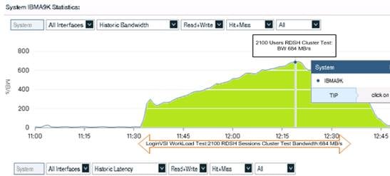
Figure 90 IBM A9000 2100 RDSH Cluster Test | Read/Write Latency
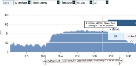
2900 Users VDI Cluster Test

 IBM FlashSystem A9000 Storage Test Results for 2900 Non-Persistent Windows 10 x64 VMware Horizon Non-Persistent Desktops
The next cluster-level simulation was to run 2900 non-persistent Windows 10 x64 desktops against the same FlashSystem A9000. All Login VSI parameters were kept consistent with brining up all 2900 desktops created via VMware Horizon Composer Provisioning virtual machines. As you can see in the below storage metrics, the IBM FlashSystem A9000 storage was clearly able to handle this workload and continued to provide sub-millisecond latency for another impressive Login VSI result. It has been observed during this component of the testing with observed peak total values 61K IOPS and Bandwidth of 1206 MB/s. The latency is less than 0.35 mil sec which is a very good end user experience.
Figure 91 IBM FlashSystem A9000 | 2900 Users VDI non-persistent Cluster Test | Read/Write IOPS

Figure 92 IBM FlashSystem A9000 | 2900 Users VDI Non-Persistent Cluster Test FlashSystem Bandwidth Transmitted /Received
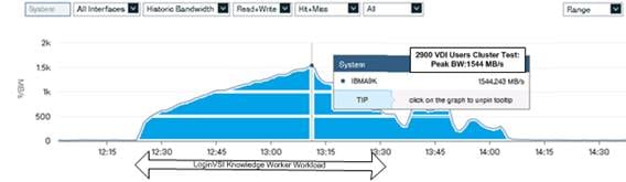
Figure 93 IBM FlashSystem A9000 | 2900 Users VDI Non-Persistent Cluster Test FlashSystem Latency (mil sec)
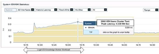
IBM FlashSystem Storage Test Results for 5000 User Full Scale, Mixed Workload Scalability
The next simulation shows the results of combining all of our previous cluster tests of 2100 VMware Horizon RDS sessions and 2900 Non-Persistent VDI Linked Clone virtual machines sessions for a full 5000 user VMware Horizon RDSH and VMware Horizon VDI simulation on the same IBM FlashSystem A9000 storage array.
Yet again you will see performance and consistent results that showcase an outstanding user experience at a very large scale.
The GUI screenshot below shows the IBM FlashSystem A9000 storage GUI with the cursor providing more detailed metrics at the start of the simulation during the boot storm of the desktops. Despite driving nearly 2GB/s in bandwidth during the test itself, we maintain the desktop responsiveness and performance of low latency throughout the entire test.
It has been observed during this component of the testing with observed peak total values 91K IOPS and a Bandwidth of 19004 MB/s. The latency is again less than 0.7 mil sec which is a very good end user experience on mixed use case scale testing scenario.
Figure 94 IBM A9000 5000 Users Mixed Workload FlashSystem Read/Write IOPS
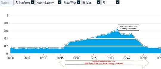
Figure 95 IBM FlashSystem A9000 | 5000 Users Mixed Workload Scale Test | Bandwidth | Transmitted /Received

Figure 96 IBM A9000 5000 Users Mixed Workload FlashSystem Read/Write IOPS

The VMware Horizon Adminsitrator Console reports all 5000 sessions /desktops (2100 RDSH sessiosn and 2900 VDI virtual machines, 2 pools each with 1450 desktops provisioned) have been logged in during the login vsi testing.
Figure 97 VMware Horizon Administrator Console
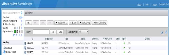
![]() This was a pristine lab environment; you can see that our data reduction and overall array utilization during this full test scenario was extremely impressive with only less than 30% of the overall array space being utilized, allowing substantial room for additional user applications, data and even additional workloads to be hosted on this array without any capacity concerns.
This was a pristine lab environment; you can see that our data reduction and overall array utilization during this full test scenario was extremely impressive with only less than 30% of the overall array space being utilized, allowing substantial room for additional user applications, data and even additional workloads to be hosted on this array without any capacity concerns.
There are many factors to consider when you begin to scale beyond 1000 Users, two chassis 8 mixed workload RDSH / VDI host server configuration, which this reference architecture has successfully tested. In this section we give guidance to scale beyond the 1000 user system.
Cisco UCS System Scalability
As our results indicate, we have proven linear scalability in the Cisco UCS Reference Architecture as tested:
· Cisco UCS Manager Software supports up to 20 Cisco UCS chassis within a single Cisco UCS domain with Cisco UCS 6248UP Fabric Interconnect. A single Cisco UCS domain can grow to 160 blades for an enterprise deployment.
· Cisco UCS Central, the manager of managers, extends Cisco UCS domains and vastly increases the reach of the Cisco UCS system. Simplify daily operations by centrally managing and automating routine tasks and expediting problem resolution. Our powerful platform eliminates disparate management environments. Use it to support up to 10,000 Cisco UCS servers (blade, rack, composable, and Mini) and manage multiple Cisco UCS instances or domains across globally-distributed locations.
· As scale grows, the value of the combined Cisco UCS fabric, Cisco Nexus physical switches, and Cisco Nexus virtual switches increases dramatically to define the Quality of Services required to deliver excellent end user experience 100 percent of the time.
· To accommodate the Cisco Nexus 9000 upstream connectivity in the way we describe in the network configuration section, two Ethernet uplinks are needed to be configured on the Cisco UCS 6248UP Fabric Interconnect.
The backend storage has to be scaled accordingly, based on the IOP considerations as described in the IBM FlashSystem A9000 storage scaling section. Please refer the IBM FlashSystem A9000 web site for scalability guidelines.
Scalability of VMware Horizon 7 Configuration
VMware Horizon environments can scale to large numbers. When implementing VMware Horizon, consider the following in scaling the number of hosted shared and hosted virtual desktops:
· Types of storage in your environment
· Types of desktops that will be deployed
· Data protection requirements
· For VMware Horizon pooled desktops, the disk size and memory requirements.
These and other various aspects of scalability considerations are described in greater detail in “VMware Horizon Reference Architecture” document and should be a part of any VMware design.
When designing and deploying this CVD environment, best practices were followed including the following:
· VMware recommends using N+1 schema for virtualization host servers to accommodate resiliency. In all Reference Architectures (such as this CVD), this recommendation is applied to all host servers.
· All Provisioning Server Network Adapters are configured to have a static IP and management.
VersaStack delivers a platform for Enterprise VDI deployments and cloud datacenters using Cisco UCS Blade and Rack Servers, Cisco Fabric Interconnects, Cisco Nexus 9000 switches, Cisco MDS switches and fibre channel-attached IBM FlashSystem A9000. VersaStack is designed and validated using compute, network and storage best practices and high availability to reduce deployment time, project risk and IT costs while maintaining scalability and flexibility for addressing a multitude of IT initiatives. This CVD validates the design, performance, management, scalability, and resilience that VersaStack provides to customers wishing to deploy enterprise-class VDI for 5000 users at a time.
Get More Business Value with Services
Whether you are planning your next-generation environment, need specialized know-how for a major deployment, or want to get the most from your current storage, Cisco Advanced Services, IBM FlashSystem A9000 storage and our certified partners can help. We collaborate with you to enhance your IT capabilities through a full portfolio of services that covers your IT lifecycle with:
· Strategy services to align IT with your business goals:
· Design services to architect your best storage environment
· Deploy and transition services to implement validated architectures and prepare your storage environment
· Operations services to deliver continuous operations while driving operational excellence and efficiency.
In addition, Cisco Advanced Services and IBM FlashSystem A9000 storage provides in-depth knowledge transfer and education services that give you access to our global technical resources and intellectual property.
Ramesh Guduru, Technical Marketing Engineer, Desktop Virtualization and Graphics Solutions, Cisco Systems, Inc.
Ramesh is a VMware Horizon and Cisco UCS subject matter expert in the Cisco Computer Systems Product Group’s Solution Team based in San Jose, CA. He has authored several Cisco Validated Designs for Horizon.
Acknowledgements
For their support and contribution to the design, validation, and creation of this Cisco Validated Design, we would like to acknowledge the significant contribution and expertise that resulted in developing this document:
· Mike Brennan, Product and Technical Marketing Manager, Desktop Virtualization and Graphics Solutions, Cisco Systems, Inc.
· Matthew Levan, Corporate Storage Architect, IBM Corporation.
This section provides links to additional information for each partner’s solution component of this document.
Cisco UCS B-Series Servers
· http://www.cisco.com/c/en/us/products/servers-unified-computing/ucs-b200-m4-blade-server/index.html
Cisco UCS Manager Configuration Guides
· http://www.cisco.com/c/en/us/td/docs/unified_computing/ucs/release/notes/CiscoUCSManager-RN-3-1.html
Cisco UCS Virtual Interface Cards
· http://www.cisco.com/c/en/us/products/interfaces-modules/ucs-virtual-interface-card-1340/index.html
Cisco Nexus Switching References
· http://www.cisco.com/c/en/us/products/switches/nexus-9372px-switch/index.html
· http://www.cisco.com/c/en/us/products/switches/nexus-1000v-switch-vmware-vsphere/index.html
Cisco MDS 9000 Service Switch References
· http://www.cisco.com/c/en/us/products/storage-networking/product-listing.html
VMware References
· https://www.vmware.com/support/pubs/vsphere-esxi-vcenter-server-6-pubs.html
· http://pubs.vmware.com/Release_Notes/en/horizon-7-view/horizon-703-view-release-notes.html
· https://labs.vmware.com/flings/vmware-os-optimization-tool
Microsoft References
· https://technet.microsoft.com/en-us/library/hh831620(v=ws.11).aspx
· https://technet.microsoft.com/en-us/library/dn281793(v=ws.11).aspx
· https://support.microsoft.com/en-us/kb/2833839
· https://technet.microsoft.com/en-us/library/hh831447(v=ws.11).aspx
Login VSI Documentation
https://www.loginvsi.com/documentation/Main_Page
https://www.loginvsi.com/documentation/Start_your_first_test
IBM Storage Reference Documents
· http://www-03.ibm.com/systems/storage/flash/a9000/
· https://www-01.ibm.com/common/ssi/cgi-bin/ssialias?htmlfid=TSD03208USEN
· http://www.redbooks.ibm.com/redpapers/pdfs/redp5325.pdf
Appendix A – Cisco Nexus Ethernet and MDS Fibre Channel Switch Configurations
Ethernet Network Configuration
The following section provides a detailed procedure for configuring the Cisco Nexus 9000 and 1000V Switches used in this study.
Cisco Nexus 9372PX-A Configuration
!Command: show running-config
!Time: Wed Mar 8 18:06:54 2017
version 7.0(3)I2(2e)
switchname DV-POD-2-N9K-A
vdc DV-Pod-2-N9K-A id 1
limit-resource vlan minimum 16 maximum 4094
limit-resource vrf minimum 2 maximum 4096
limit-resource port-channel minimum 0 maximum 511
limit-resource u4route-mem minimum 248 maximum 248
limit-resource u6route-mem minimum 96 maximum 96
limit-resource m4route-mem minimum 58 maximum 58
limit-resource m6route-mem minimum 8 maximum 8
feature telnet
cfs ipv4 distribute
cfs eth distribute
feature udld
feature interface-vlan
feature hsrp
feature lacp
feature dhcp
feature vpc
feature lldp
clock protocol none vdc 1
no password strength-check
username admin password 5 $1$tYYajkfc$7P7nLjWYvfTWAlvFDnwJZ. role network-admin
ssh key rsa 2048
ip domain-lookup
no service unsupported-transceiver
copp profile strict
snmp-server user admin network-admin auth md5 0xf747567d6cfecf362a9641ac6f3cefc9 priv 0xf747567d6cfecf362a9641ac6f3cefc9 localizedkey
rmon event 1 log trap public description FATAL(1) owner PMON@FATAL
rmon event 2 log trap public description CRITICAL(2) owner PMON@CRITICAL
rmon event 3 log trap public description ERROR(3) owner PMON@ERROR
rmon event 4 log trap public description WARNING(4) owner PMON@WARNING
rmon event 5 log trap public description INFORMATION(5) owner PMON@INFO
ntp server 10.10.160.2
ntp peer 10.10.160.3
ntp server 10.81.254.202 use-vrf management
vlan 1-2,60-70,102,164
vlan 60
name In-Band-Mgmt
vlan 61
name Infra-Mgmt
vlan 66
name vMotion
vlan 67
name N1KV
vlan 68
name LauncherPXE
vlan 102
name VDI
vlan 164
name Out-Of-Band-Mgmt
spanning-tree port type edge bpduguard default
spanning-tree port type edge bpdufilter default
spanning-tree port type network default
service dhcp
ip dhcp relay
ipv6 dhcp relay
vrf context management
ip route 0.0.0.0/0 10.29.164.1
port-channel load-balance src-dst l4port
hardware qos ns-buffer-profile mesh
vpc domain 10
peer-switch
role priority 10
peer-keepalive destination 10.29.164.66 source 10.29.164.65
delay restore 150
peer-gateway
auto-recovery
interface Vlan1
description default native vlan
no shutdown
no ip redirects
ip address 10.29.164.253/24
no ipv6 redirects
interface Vlan60
description In Band Mgmt vlan 60
no shutdown
no ip redirects
ip address 10.10.60.2/24
hsrp version 2
hsrp 60
preempt
ip 10.10.60.1
interface Vlan61
description Infrastructure vlan 61
no shutdown
no ip redirects
ip address 10.10.61.2/24
no ipv6 redirects
hsrp version 2
hsrp 61
preempt
ip 10.10.61.1
interface Vlan66
description vMotion network vlan 66
no shutdown
ip address 10.10.66.2/24
hsrp version 2
hsrp 66
preempt
ip 10.10.66.1
interface Vlan67
description Nexus1000v vlan 67
no shutdown
ip address 10.10.67.2/24
hsrp version 2
hsrp 67
preempt
ip 10.10.67.1
interface Vlan68
description VSI Launchers vlan 68
no shutdown
ip address 10.10.68.2/23
hsrp version 2
hsrp 68
preempt
ip 10.10.68.1
ip dhcp relay address 10.10.61.30
interface Vlan102
description VDI vlan 102
no shutdown
ip address 10.2.2/19
no ipv6 redirects
hsrp version 2
hsrp 102
preempt delay minimum 240
priority 110
ip 10.2.0.1
ip dhcp relay address 10.10.61.30
ip dhcp relay address 10.10.61.31
interface port-channel10
description VPC peer-link
switchport mode trunk
switchport trunk allowed vlan 1,60-70,102,164
spanning-tree port type network
vpc peer-link
interface port-channe11
description FI-A_6k_UCS-Uplink
switchport mode trunk
switchport trunk allowed vlan 1,60-70,102,164
spanning-tree port type edge trunk
mtu 9216
vpc 11
interface port-channel2
description FI-B_6k_UCS-Uplink
switchport mode trunk
switchport trunk allowed vlan 1,60-70,102-164
spanning-tree port type edge trunk
mtu 9216
vpc 12
interface port-channel15
description FI-A_6k_Launchers-Uplink
switchport mode trunk
switchport trunk allowed vlan 1,60-70,102,164
spanning-tree port type edge trunk
mtu 9216
vpc 15
interface port-channel16
description FI-B_6k_Launchers-Uplink
switchport mode trunk
switchport trunk allowed vlan 1,60-70,102,164
spanning-tree port type edge trunk
mtu 9216
vpc 16
interface Ethernet1/1
interface Ethernet1/2
interface Ethernet1/3
interface Ethernet1/4
interface Ethernet1/5
interface Ethernet1/6
interface Ethernet1/7
interface Ethernet1/8
interface Ethernet1/9
interface Ethernet1/10
interface Ethernet1/11
interface Ethernet1/12
interface Ethernet1/13
interface Ethernet1/14
interface Ethernet1/15
interface Ethernet1/16
interface Ethernet1/17
description Uplink_from_FI-A_6k
switchport mode trunk
switchport trunk allowed vlan 1,60-70,102,164
mtu 9216
channel-group 11 mode active
interface Ethernet1/18
description Uplink_from_FI-A_6k
switchport mode trunk
switchport trunk allowed vlan 1,60-70,102,164
mtu 9216
channel-group 11 mode active
interface Ethernet1/19
description Uplink_from_FI-B_6k
switchport mode trunk
switchport trunk allowed vlan 1,60-70,102,164
mtu 9216
channel-group 12 mode active
interface Ethernet1/20
description Uplink_from_FI-B_6k
switchport mode trunk
switchport trunk allowed vlan 1,60-70,102,164
mtu 9216
interface Ethernet1/21
interface Ethernet1/22
interface Ethernet1/23
interface Ethernet1/24
interface Ethernet1/25
interface Ethernet1/26
interface Ethernet1/27
interface Ethernet1/28
interface Ethernet1/29
interface Ethernet1/30
interface Ethernet1/31
interface Ethernet1/32
interface Ethernet1/33
interface Ethernet1/34
interface Ethernet1/35
interface Ethernet1/36
interface Ethernet1/37
interface Ethernet1/38
interface Ethernet1/39
interface Ethernet1/40
interface Ethernet1/41
interface Ethernet1/42
interface Ethernet1/43
interface Ethernet1/44
interface Ethernet1/45
description Uplink_from_LoginVSI_Launchers_FI-A
switchport mode trunk
switchport trunk allowed vlan 1,60-70,102,164
mtu 9216
channel-group 15 mode active
interface Ethernet1/46
description Uplink_from_LoginVSI_Launchers_FI-B
switchport mode trunk
switchport trunk allowed vlan 1,60-70,102,164
mtu 9216
interface Ethernet1/47
interface Ethernet1/48
interface Ethernet1/49
description VPC Peer Link between 9ks
switchport mode trunk
switchport trunk allowed vlan 1,60-70,102,164
channel-group 10 mode active
interface Ethernet1/50
description VPC Peer Link between 9ks
switchport mode trunk
switchport trunk allowed vlan 1,60-70,102,164
channel-group 10 mode active
interface Ethernet1/51
interface Ethernet1/52
interface Ethernet1/53
interface Ethernet1/54
interface mgmt0
vrf member management
ip address 10.29.164.65/24
line console
line vty
boot nxos bootflash://sup-1/n9000-dk9.7.0.3.I1.3b.bin
Cisco Nexus 9172PX-B Configuration
DV-Pod-2-N9K-B# show running-config
!Command: show running-config
!Time: Wed Mar 8 18:17:44 2017
version 7.0(3)I1(3b)
switchname DV-Pod-2-N9K-B
vdc N9K-B id 1
limit-resource vlan minimum 16 maximum 4094
limit-resource vrf minimum 2 maximum 4096
limit-resource port-channel minimum 0 maximum 511
limit-resource u4route-mem minimum 248 maximum 248
limit-resource u6route-mem minimum 96 maximum 96
limit-resource m4route-mem minimum 58 maximum 58
limit-resource m6route-mem minimum 8 maximum 8
feature telnet
cfs ipv4 distribute
cfs eth distribute
feature udld
feature interface-vlan
feature hsrp
feature lacp
feature dhcp
feature vpc
feature lldp
clock protocol none vdc 1
no password strength-check
username admin password 5 $1$fp3LrGLC$PF8eML85qkPBgdH/bZAKK/ role network-admin
ip domain-lookup
system default switchport shutdown
no service unsupported-transceiver
copp profile strict
rmon event 1 log trap public description FATAL(1) owner PMON@FATAL
rmon event 2 log trap public description CRITICAL(2) owner PMON@CRITICAL
rmon event 3 log trap public description ERROR(3) owner PMON@ERROR
rmon event 4 log trap public description WARNING(4) owner PMON@WARNING
rmon event 5 log trap public description INFORMATION(5) owner PMON@INFO
ntp peer 10.10.160.2
ntp server 10.10.160.3
ntp server 171.68.38.66 use-vrf management
ntp master 8
vlan 1,60-70,102,164
vlan 60
name In-Band-Mgmt
vlan 61
name Infra-Mgmt
vlan 66
name vMotion
vlan 67
name N1KV
vlan 68
name LauncherPXE
vlan 102
name VDI
spanning-tree port type edge bpduguard default
spanning-tree port type edge bpdufilter default
spanning-tree port type network default
service dhcp
ip dhcp relay
ipv6 dhcp relay
vrf context management
ip route 0.0.0.0/0 10.29.164.1
port-channel load-balance src-dst l4port
hardware qos ns-buffer-profile mesh
vpc domain 10
role priority 20
peer-keepalive destination 10.29.164.65 source 10.29.164.66
delay restore 150
peer-gateway
auto-recovery
interface Vlan1
description default native vlan
no shutdown
no ip redirects
ip address 10.29.164.254/24
no ipv6 redirects
interface Vlan60
description In Band Mmgmt vlan 60
no shutdown
no ip redirects
ip address 10.10.60.3/24
hsrp version 2
hsrp 60
preempt
ip 10.10.60.1
interface Vlan61
description Infrastructure Mgmt vlan 61
no shutdown
no ip redirects
ip address 10.10.61.3/24
no ipv6 redirects
hsrp version 2
hsrp 61
preempt
ip 10.10.61.1
interface Vlan66
description vMotion network vlan 66
no shutdown
ip address 10.10.66.3/24
hsrp version 2
hsrp 66
preempt
ip 10.10.66.1
interface Vlan67
description Nexus 1000v vlan 67
no shutdown
ip address 10.10.67.3/24
hsrp version 2
hsrp 67
preempt
ip 10.10.67.1
interface Vlan68
description LoginVSI Launchers vlan 68
no shutdown
no ip redirects
ip address 10.10.68.3/23
no ipv6 redirects
hsrp version 2
hsrp 68
preempt
ip 10.10.68.1
ip dhcp relay address 10.10.61.30
interface Vlan102
description VDI vlan 102
no shutdown
no ip redirects
ip address 10.2.0.3/19
no ipv6 redirects
hsrp version 2
hsrp 102
preempt delay minimum 240
priority 110
ip 10.2.0.1
ip dhcp relay address 10.10.61.30
ip dhcp relay address 10.10.61.31
interface port-channel10
description VPC peer-link
switchport mode trunk
switchport trunk allowed vlan 1,60-70,102,164
spanning-tree port type network
vpc peer-link
interface port-channel11
description FI-A_6k_UCS-Uplink
switchport mode trunk
switchport trunk allowed vlan 1,60-70,102,164
spanning-tree port type edge trunk
mtu 9216
vpc 11
interface port-channel12
description FI-B_6k_UCS-Uplink
switchport mode trunk
switchport trunk allowed vlan 1,60-70,102,164
spanning-tree port type edge trunk
mtu 9216
vpc 12
interface port-channel15
description FI-A_6k_Launchers-Uplink
switchport mode trunk
switchport trunk allowed vlan 1,60-70,102,164
spanning-tree port type edge trunk
mtu 9216
vpc 15
interface port-channel16
description FI-B_6k_Launchers-Uplink
switchport mode trunk
switchport trunk allowed vlan 1,60-70,102,164
spanning-tree port type edge trunk
mtu 9216
vpc 16
interface Ethernet1/1
interface Ethernet1/2
interface Ethernet1/3
interface Ethernet1/4
interface Ethernet1/5
interface Ethernet1/6
interface Ethernet1/7
interface Ethernet1/8
interface Ethernet1/9
interface Ethernet1/10
interface Ethernet1/11
interface Ethernet1/12
interface Ethernet1/13
interface Ethernet1/14
interface Ethernet1/15
interface Ethernet1/16
interface Ethernet1/17
description Uplink_from_FI-A_6k
switchport mode trunk
switchport trunk allowed vlan 1,60-70,102,164
mtu 9216
channel-group 11 mode active
interface Ethernet1/18
description Uplink_from_FI-A_6k
switchport mode trunk
switchport trunk allowed vlan 1,60-70,102,164
mtu 9216
channel-group 11 mode active
interface Ethernet1/19
description Uplink_from_FI-B_6k
switchport mode trunk
switchport trunk allowed vlan 1,60-70,102,164
mtu 9216
channel-group 12 mode active
interface Ethernet1/20
description Uplink_from_FI-B_6k
switchport mode trunk
switchport trunk allowed vlan 1,60-70,102,164
mtu 9216
channel-group 12 mode active
interface Ethernet1/21
interface Ethernet1/22
interface Ethernet1/23
interface Ethernet1/24
interface Ethernet1/25
interface Ethernet1/26
interface Ethernet1/27
interface Ethernet1/28
interface Ethernet1/29
interface Ethernet1/30
interface Ethernet1/31
interface Ethernet1/32
interface Ethernet1/33
interface Ethernet1/34
interface Ethernet1/35
interface Ethernet1/36
interface Ethernet1/37
interface Ethernet1/38
interface Ethernet1/39
interface Ethernet1/40
interface Ethernet1/41
interface Ethernet1/42
interface Ethernet1/43
interface Ethernet1/44
interface Ethernet1/45
description Uplink_from_LoginVSI_Launchers_FI-A
switchport mode trunk
switchport trunk allowed vlan 1,60-70,102,164
mtu 9216
channel-group 15 mode active
interface Ethernet1/46
description Uplink_from_LoginVSI_Launchers_FI-B
switchport mode trunk
switchport trunk allowed vlan 1,60-70,102,164
mtu 9216
channel-group 16 mode active
interface Ethernet1/47
interface Ethernet1/48
interface Ethernet1/49
description VPC Peer Link between 9ks
switchport mode trunk
switchport trunk allowed vlan 1,60-70,102,164
channel-group 10 mode active
interface Ethernet1/50
description VPC Peer Link between 9ks
switchport mode trunk
switchport trunk allowed vlan 1,60-70,102,164
channel-group 10 mode active
interface Ethernet1/51
interface Ethernet1/52
interface Ethernet1/53
interface Ethernet1/54
ip address 10.29.164.66/24
line console
line vty
boot nxos bootflash://sup-1/n9000-dk9.7.0.3.I1.3b.bin
Fibre Channel Network Configuration
Cisco MDS 9148S-A Configuration
!Command: show running-config
!Time: Wed Mar 8 21:46:34 2017
version 6.2(9a)
username admin password 5 $1$loX7vizP$00IbhSFcpx6WufBmOMKB.1 role network-admin
ip domain-lookup
ip host MDS-A 10.29.164.64
aaa group server radius radius
snmp-server user admin network-admin auth md5 0x6c81eb7167a2e69497a60698ca3957da
priv 0x6c81eb7167a2e69497a60698ca3957da localizedkey
rmon event 1 log trap public description FATAL(1) owner PMON@FATAL
rmon event 2 log trap public description CRITICAL(2) owner PMON@CRITICAL
rmon event 3 log trap public description ERROR(3) owner PMON@ERROR
rmon event 4 log trap public description WARNING(4) owner PMON@WARNING
rmon event 5 log trap public description INFORMATION(5) owner PMON@INFO
vsan database
vsan 300
device-alias database
vsan 300 wwn 20:00:00:25:b5:03:9a:08 fcid 0xa30a02 dynamic[Infra01_HBA1]
vsan 300 wwn 20:00:00:25:b5:03:9a:0a fcid 0xa30b02 dynamic[Infra02_HBA1]
vsan 300 wwn 20:00:00:25:b5:03:9a:12 fcid 0xa30c09 dynamic[srv01_HBA1]
vsan 300 wwn 20:00:00:25:b5:03:9a:14 fcid 0xa30909 dynamic[srv02_HBA1]
vsan 300 wwn 20:00:00:25:b5:03:9a:0e fcid 0xa30a09 dynamic[srv03_HBA1]
vsan 300 wwn 20:00:00:25:b5:03:9a:00 fcid 0xa3090a dynamic[srv04_HBA1]
vsan 300 wwn 20:00:00:25:b5:03:9a:02 fcid 0xa30a01 dynamic[srv05_HBA1]
vsan 300 wwn 20:00:00:25:b5:03:9a:0c fcid 0xa30c03 dynamic[srv06_HBA1]
vsan 300 wwn 20:00:00:25:b5:03:9a:10 fcid 0xa30c03 dynamic[srv07_HBA1]
vsan 300 wwn 20:00:00:25:b5:03:9a:16 fcid 0xa30903 dynamic[srv09_HBA1]
vsan 300 wwn 20:00:00:25:b5:03:9a:18 fcid 0xa30b04 dynamic[srv10_HBA1]
vsan 300 wwn 20:00:00:25:b5:03:9a:1a fcid 0xa30c02 dynamic[srv11_HBA1]
vsan 300 wwn 20:00:00:25:b5:03:9a:1c fcid 0xa30a07 dynamic[srv12_HBA1]
vsan 300 wwn 20:00:00:25:b5:03:9a:1e fcid 0xa30a04 dynamic[srv13_HBA1]
vsan 300 wwn 20:00:00:25:b5:03:9a:20 fcid 0xa30b08 dynamic[srv14_HBA1]
vsan 300 wwn 20:00:00:25:b5:03:9a:22 fcid 0xa30b08 dynamic[srv15_HBA1]
vsan 300 wwn 20:00:00:25:b5:03:9a:24 fcid 0xa30c06 dynamic[srv17_HBA1]
vsan 300 wwn 20:00:00:25:b5:03:9a:26 fcid 0xa30904 dynamic[srv18_HBA1]
vsan 300 wwn 20:00:00:25:b5:03:9a:30 fcid 0xa30b03 dynamic[srv19_HBA1]
vsan 300 wwn 20:00:00:25:b5:03:9a:28 fcid 0xa30907 dynamic[srv20_HBA1]
vsan 300 wwn 20:00:00:25:b5:03:9a:2a fcid 0xa30a03 dynamic[srv21_HBA1]
vsan 300 wwn 20:00:00:25:b5:03:9a:2c fcid 0xa30b05 dynamic[srv22_HBA1]
vsan 300 wwn 20:00:00:25:b5:03:9a:2e fcid 0xa30b08 dynamic[srv23_HBA1]
vsan 300 wwn 20:00:00:25:b5:03:9a:32 fcid 0xa30b06 dynamic[srv24_HBA1]
vsan 300 wwn 20:00:00:25:b5:03:9a:34 fcid 0xa30906 dynamic[srv25_HBA1]
vsan 300 wwn 20:00:00:25:b5:03:9a:36 fcid 0xa30a05 dynamic[srv26_HBA1]
vsan 300 wwn 20:00:00:25:b5:03:9a:38 fcid 0xa30a08 dynamic[srv27_HBA1]
vsan 300 wwn 20:00:00:25:b5:03:9a:3a fcid 0xa30c07 dynamic[srv28_HBA1]
vsan 300 wwn 20:00:00:25:b5:03:9a:3c fcid 0xa30c08 dynamic[srv29_HBA1]
vsan 300 wwn 20:00:00:25:b5:03:9a:3e fcid 0xa30b07 dynamic[srv30_HBA1]
vsan 300 wwn 20:00:00:25:b5:03:9a:40 fcid 0xa30b08 dynamic[srv31_HBA1]
vsan 300 wwn 20:00:00:25:b5:03:9a:42 fcid 0xa30905 dynamic[srv32_HBA1]
interface port-channel1
channel mode active
switchport rate-mode dedicated
vsan database
vsan 300 interface fc1/37
vsan 300 interface fc1/38
vsan 300 interface fc1/39
vsan 300 interface fc1/40
vsan 300 interface fc1/43
vsan 300 interface fc1/44
vsan 300 interface fc1/45
vsan 300 interface fc1/46
vsan 300 interface fc1/47
vsan 300 interface fc1/48
switchname MDS-A
line console
line vty
boot kickstart bootflash:/m9100-s5ek9-kickstart-mz.6.2.9a.bin
boot system bootflash:/m9100-s5ek9-mz.6.2.9a.bin
interface fc1/1
interface fc1/2
interface fc1/3
interface fc1/4
interface fc1/5
interface fc1/6
interface fc1/7
interface fc1/8
interface fc1/9
interface fc1/10
interface fc1/13
interface fc1/11
interface fc1/12
interface fc1/14
interface fc1/15
interface fc1/16
interface fc1/17
interface fc1/18
interface fc1/19
interface fc1/20
interface fc1/21
interface fc1/22
interface fc1/23
interface fc1/24
interface fc1/25
interface fc1/26
interface fc1/27
interface fc1/28
interface fc1/29
interface fc1/30
interface fc1/31
interface fc1/32
interface fc1/33
interface fc1/34
interface fc1/35
interface fc1/36
interface fc1/37
interface fc1/38
interface fc1/39
interface fc1/40
interface fc1/41
interface fc1/42
interface fc1/43
interface fc1/44
interface fc1/45
interface fc1/46
interface fc1/47
interface fc1/48
!Active Zone Database Section for vsan 300
zone name Infra01_HBA1__A9000_1 vsan 300
member pwwn 20:00:00:25:b5:03:9a:08[Infra01_HBA1]
member pwwn 50:01:73:80:59:16:01:12[A9000_N1P3]
member pwwn 50:01:73:80:59:16:01:22[A9000_N2P3]
member pwwn 50:01:73:80:59:16:01:32[A9000_N3P3]
zone name Infra02_HBA1__A9000_1 vsan 300
member pwwn 20:00:00:25:b5:03:9a:0a[Infra02_HBA1]
member pwwn 50:01:73:80:59:16:01:12[A9000_N1P3]
member pwwn 50:01:73:80:59:16:01:22[A9000_N2P3]
member pwwn 50:01:73:80:59:16:01:32[A9000_N3P3]
zone name srv01_HBA1__A9000_1 vsan 300
member pwwn 20:00:00:25:b5:03:9a:12[srv01_HBA1]
member pwwn 50:01:73:80:59:16:01:10[A9000_N1P1]
member pwwn 50:01:73:80:59:16:01:20[A9000_N2P1]
member pwwn 50:01:73:80:59:16:01:30[A9000_N3P1]
zone name srv02_HBA1__A9000_1 vsan 300
member pwwn 20:00:00:25:b5:03:9a:14[srv02_HBA1]
member pwwn 50:01:73:80:59:16:01:12[A9000_N1P3]
member pwwn 50:01:73:80:59:16:01:22[A9000_N2P3]
member pwwn 50:01:73:80:59:16:01:32[A9000_N3P3]
zone name srv03_HBA1__A9000_1 vsan 300
member pwwn 20:00:00:25:b5:03:9a:0e[srv03_HBA1]
member pwwn 50:01:73:80:59:16:01:10[A9000_N1P1]
member pwwn 50:01:73:80:59:16:01:20[A9000_N2P1]
member pwwn 50:01:73:80:59:16:01:30[A9000_N3P1]
zone name srv04_HBA1__A9000_1 vsan 300
member pwwn 20:00:00:25:b5:03:9a:00[srv04_HBA1]
member pwwn 50:01:73:80:59:16:01:12[A9000_N1P3]
member pwwn 50:01:73:80:59:16:01:22[A9000_N2P3]
member pwwn 50:01:73:80:59:16:01:32[A9000_N3P3]
zone name srv05_HBA1__A9000_1 vsan 300
member pwwn 20:00:00:25:b5:03:9a:02[srv05_HBA1]
member pwwn 50:01:73:80:59:16:01:10[A9000_N1P1]
member pwwn 50:01:73:80:59:16:01:20[A9000_N2P1]
member pwwn 50:01:73:80:59:16:01:30[A9000_N3P1]
zone name srv06_HBA1__A9000_1 vsan 300
member pwwn 20:00:00:25:b5:03:9a:0c[srv06_HBA1]
member pwwn 50:01:73:80:59:16:01:12[A9000_N1P3]
member pwwn 50:01:73:80:59:16:01:22[A9000_N2P3]
member pwwn 50:01:73:80:59:16:01:32[A9000_N3P3]
zone name srv07_HBA1__A9000_1 vsan 300
member pwwn 20:00:00:25:b5:03:9a:10[srv07_HBA1]
member pwwn 50:01:73:80:59:16:01:10[A9000_N1P1]
member pwwn 50:01:73:80:59:16:01:20[A9000_N2P1]
member pwwn 50:01:73:80:59:16:01:30[A9000_N3P1]
zone name srv09_HBA1__A9000_1 vsan 300
member pwwn 20:00:00:25:b5:03:9a:16[srv09_HBA1]
member pwwn 50:01:73:80:59:16:01:10[A9000_N1P1]
member pwwn 50:01:73:80:59:16:01:20[A9000_N2P1]
member pwwn 50:01:73:80:59:16:01:30[A9000_N3P1]
zone name srv10_HBA1__A9000_1 vsan 300
member pwwn 20:00:00:25:b5:03:9a:18[srv10_HBA1]
member pwwn 50:01:73:80:59:16:01:12[A9000_N1P3]
member pwwn 50:01:73:80:59:16:01:22[A9000_N2P3]
member pwwn 50:01:73:80:59:16:01:32[A9000_N3P3]
zone name srv11_HBA1__A9000_1 vsan 300
member pwwn 20:00:00:25:b5:03:9a:1a[srv11_HBA1]
member pwwn 50:01:73:80:59:16:01:10[A9000_N1P1]
member pwwn 50:01:73:80:59:16:01:20[A9000_N2P1]
member pwwn 50:01:73:80:59:16:01:30[A9000_N3P1]
zone name srv12_HBA1__A9000_1 vsan 300
member pwwn 20:00:00:25:b5:03:9a:1c[srv12_HBA1]
member pwwn 50:01:73:80:59:16:01:12[A9000_N1P3]
member pwwn 50:01:73:80:59:16:01:22[A9000_N2P3]
member pwwn 50:01:73:80:59:16:01:32[A9000_N3P3]
zone name srv13_HBA1__A9000_1 vsan 300
member pwwn 20:00:00:25:b5:03:9a:1e[srv13_HBA1]
member pwwn 50:01:73:80:59:16:01:10[A9000_N1P1]
member pwwn 50:01:73:80:59:16:01:20[A9000_N2P1]
member pwwn 50:01:73:80:59:16:01:30[A9000_N3P1]
zone name srv14_HBA1__A9000_1 vsan 300
member pwwn 20:00:00:25:b5:03:9a:20[srv14_HBA1]
member pwwn 50:01:73:80:59:16:01:12[A9000_N1P3]
member pwwn 50:01:73:80:59:16:01:22[A9000_N2P3]
member pwwn 50:01:73:80:59:16:01:32[A9000_N3P3]
zone name srv15_HBA1__A9000_1 vsan 300
member pwwn 20:00:00:25:b5:03:9a:22[srv23_HBA1]
member pwwn 50:01:73:80:59:16:01:10[A9000_N1P1]
member pwwn 50:01:73:80:59:16:01:20[A9000_N2P1]
member pwwn 50:01:73:80:59:16:01:30[A9000_N3P1]
zone name srv17_HBA1__A9000_1 vsan 300
member pwwn 20:00:00:25:b5:03:9a:24[srv17_HBA1]
member pwwn 50:01:73:80:59:16:01:10[A9000_N1P1]
member pwwn 50:01:73:80:59:16:01:20[A9000_N2P1]
member pwwn 50:01:73:80:59:16:01:30[A9000_N3P1]
zone name srv18_HBA1__A9000_1 vsan 300
member pwwn 20:00:00:25:b5:03:9a:26[srv18_HBA1]
member pwwn 50:01:73:80:59:16:01:12[A9000_N1P3]
member pwwn 50:01:73:80:59:16:01:22[A9000_N2P3]
member pwwn 50:01:73:80:59:16:01:32[A9000_N3P3]
zone name srv19_HBA1__A9000_1 vsan 300
member pwwn 20:00:00:25:b5:03:9a:30[srv19_HBA1]
member pwwn 50:01:73:80:59:16:01:10[A9000_N1P1]
member pwwn 50:01:73:80:59:16:01:20[A9000_N2P1]
member pwwn 50:01:73:80:59:16:01:30[A9000_N3P1]
zone name srv20_HBA1__A9000_1 vsan 300
member pwwn 20:00:00:25:b5:03:9a:28[srv20_HBA1]
member pwwn 50:01:73:80:59:16:01:12[A9000_N1P3]
member pwwn 50:01:73:80:59:16:01:22[A9000_N2P3]
member pwwn 50:01:73:80:59:16:01:32[A9000_N3P3]
zone name srv21_HBA1__A9000_1 vsan 300
member pwwn 20:00:00:25:b5:03:9a:2a[srv21_HBA1]
member pwwn 50:01:73:80:59:16:01:10[A9000_N1P1]
member pwwn 50:01:73:80:59:16:01:20[A9000_N2P1]
member pwwn 50:01:73:80:59:16:01:30[A9000_N3P1]
zone name srv22_HBA1__A9000_1 vsan 300
member pwwn 20:00:00:25:b5:03:9a:2c[srv22_HBA1]
member pwwn 50:01:73:80:59:16:01:12[A9000_N1P3]
member pwwn 50:01:73:80:59:16:01:22[A9000_N2P3]
member pwwn 50:01:73:80:59:16:01:32[A9000_N3P3]
zone name srv23_HBA1__A9000_1 vsan 300
member pwwn 20:00:00:25:b5:03:9a:2e[srv23_HBA1]
member pwwn 50:01:73:80:59:16:01:10[A9000_N1P1]
member pwwn 50:01:73:80:59:16:01:20[A9000_N2P1]
member pwwn 50:01:73:80:59:16:01:30[A9000_N3P1]
zone name srv24_HBA1__A9000_1 vsan 300
member pwwn 20:00:00:25:b5:03:9a:32[srv24_HBA1]
member pwwn 50:01:73:80:59:16:01:12[A9000_N1P3]
member pwwn 50:01:73:80:59:16:01:22[A9000_N2P3]
member pwwn 50:01:73:80:59:16:01:32[A9000_N3P3]
zone name srv25_HBA1__A9000_1 vsan 300
member pwwn 20:00:00:25:b5:03:9a:34[srv25_HBA1]
member pwwn 50:01:73:80:59:16:01:10[A9000_N1P1]
member pwwn 50:01:73:80:59:16:01:20[A9000_N2P1]
member pwwn 50:01:73:80:59:16:01:30[A9000_N3P1]
zone name srv26_HBA1__A9000_1 vsan 300
member pwwn 20:00:00:25:b5:03:9a:36[srv26_HBA1]
member pwwn 50:01:73:80:59:16:01:12[A9000_N1P3]
member pwwn 50:01:73:80:59:16:01:22[A9000_N2P3]
member pwwn 50:01:73:80:59:16:01:32[A9000_N3P3]
zone name srv27_HBA1__A9000_1 vsan 300
member pwwn 20:00:00:25:b5:03:9a:38[srv27_HBA1]
member pwwn 50:01:73:80:59:16:01:10[A9000_N1P1]
member pwwn 50:01:73:80:59:16:01:20[A9000_N2P1]
member pwwn 50:01:73:80:59:16:01:30[A9000_N3P1]
zone name srv28_HBA1__A9000_1 vsan 300
member pwwn 20:00:00:25:b5:03:9a:3a[srv28_HBA1]
member pwwn 50:01:73:80:59:16:01:12[A9000_N1P3]
member pwwn 50:01:73:80:59:16:01:22[A9000_N2P3]
member pwwn 50:01:73:80:59:16:01:32[A9000_N3P3]
zone name srv29_HBA1__A9000_1 vsan 300
member pwwn 20:00:00:25:b5:03:9a:3c[srv29_HBA1]
member pwwn 50:01:73:80:59:16:01:10[A9000_N1P1]
member pwwn 50:01:73:80:59:16:01:20[A9000_N2P1]
member pwwn 50:01:73:80:59:16:01:30[A9000_N3P1]
zone name srv30_HBA1__A9000_1 vsan 300
member pwwn 20:00:00:25:b5:03:9a:3e[srv30_HBA1]
member pwwn 50:01:73:80:59:16:01:12[A9000_N1P3]
member pwwn 50:01:73:80:59:16:01:22[A9000_N2P3]
member pwwn 50:01:73:80:59:16:01:32[A9000_N3P3]
zone name srv31_HBA1__A9000_1 vsan 300
member pwwn 20:00:00:25:b5:03:9a:40[srv31_HBA1]
member pwwn 50:01:73:80:59:16:01:10[A9000_N1P1]
member pwwn 50:01:73:80:59:16:01:20[A9000_N2P1]
member pwwn 50:01:73:80:59:16:01:30[A9000_N3P1]
zone name srv32_HBA1__A9000_1 vsan 300
member pwwn 20:00:00:25:b5:03:9a:42[srv32_HBA1]
member pwwn 50:01:73:80:59:16:01:12[A9000_N1P3]
member pwwn 50:01:73:80:59:16:01:22[A9000_N2P3]
member pwwn 50:01:73:80:59:16:01:32[A9000_N3P3]
zoneset name A9000_VDI vsan 300
member Infra01_HBA1__A9000_1
member Infra02_HBA1__A9000_1
member srv01_HBA1__A9000_1
member srv02_HBA1__A9000_1
member srv03_HBA1__A9000_1
member srv04_HBA1__A9000_1
member srv05_HBA1__A9000_1
member srv06_HBA1__A9000_1
member srv07_HBA1__A9000_1
member srv09_HBA1__A9000_1
member srv10_HBA1__A9000_1
member srv11_HBA1__A9000_1
member srv12_HBA1__A9000_1
member srv13_HBA1__A9000_1
member srv14_HBA1__A9000_1
member srv15_HBA1__A9000_1
member srv17_HBA1__A9000_1
member srv18_HBA1__A9000_1
member srv19_HBA1__A9000_1
member srv20_HBA1__A9000_1
member srv21_HBA1__A9000_1
member srv22_HBA1__A9000_1
member srv23_HBA1__A9000_1
member srv24_HBA1__A9000_1
member srv25_HBA1__A9000_1
member srv26_HBA1__A9000_1
member srv27_HBA1__A9000_1
member srv28_HBA1__A9000_1
member srv29_HBA1__A9000_1
member srv30_HBA1__A9000_1
member srv31_HBA1__A9000_1
member srv32_HBA1__A9000_1
zoneset activate name A9000_VDI vsan 300
do clear zone database vsan 300
!Full Zone Database Section for vsan 30
interface fc1/1
switchport trunk mode off
port-license acquire
no shutdown
interface fc1/2
switchport trunk mode off
port-license acquire
no shutdown
interface fc1/3
switchport trunk mode off
port-license acquire
no shutdown
interface fc1/4
switchport trunk mode off
port-license acquire
no shutdown
interface fc1/5
port-license acquire
interface fc1/6
port-license acquire
interface fc1/7
no port-license
no shutdown
interface fc1/8
no port-license
no shutdown
interface fc1/9
port-license acquire
no shutdown
interface fc1/10
port-license acquire
no shutdown
interface fc1/11
port-license acquire
channel-group 1 force
no shutdown
interface fc1/12
port-license acquire
channel-group 1 force
no shutdown
interface fc1/13
port-license acquire
no shutdown
interface fc1/14
port-license acquire
no shutdown
interface fc1/15
port-license acquire
no shutdown
interface fc1/16
port-license acquire
no shutdown
interface fc1/17
port-license acquire
interface fc1/18
port-license acquire
interface fc1/19
port-license acquire
interface fc1/20
port-license acquire
interface fc1/21
port-license acquire
interface fc1/22
port-license acquire
interface fc1/23
port-license acquire
interface fc1/24
port-license acquire
interface fc1/25
port-license acquire
interface fc1/26
port-license acquire
interface fc1/27
port-license acquire
interface fc1/28
port-license acquire
interface fc1/29
port-license acquire
interface fc1/30
port-license acquire
interface fc1/31
port-license acquire
interface fc1/32
interface fc1/33
port-license acquire
interface fc1/34
port-license acquire
interface fc1/35
port-license acquire
interface fc1/36
port-license acquire
interface fc1/37
port-license acquire
interface fc1/38
port-license acquire
interface fc1/39
port-license acquire
interface fc1/40
port-license acquire
interface fc1/41
port-license acquire
interface fc1/42
port-license acquire
interface fc1/43
port-license acquire
interface fc1/44
port-license acquire
interface fc1/45
port-license acquire
interface fc1/46
port-license acquire
interface fc1/47
port-license acquire
interface fc1/48
port-license acquire
interface mgmt0
ip address 10.29.164.64 255.255.255.0
ip default-gateway 10.29.164.1
MDS-A#
Cisco MDS 9148S-B Configuration
!Time: Wed Mar 8 23:03:47 2017
version 6.2(9a)
power redundancy-mode redundant
feature npiv
feature fport-channel-trunk
role name default-role
description This is a system defined role and applies to all users.
rule 5 permit show feature environment
rule 4 permit show feature hardware
rule 3 permit show feature module
rule 2 permit show feature snmp
rule 1 permit show feature system
username admin password 5 $1$dcmFCg/p$0ZC5U6uhI65oOePpHfAzn0 role network-admin
no password strength-check
ip domain-lookup
ip host MDS-B 10.29.164.128
aaa group server radius radius
snmp-server user admin network-admin auth md5 0xc9e1af5dbb0bbac72253a1bef037bbbe
priv 0xc9e1af5dbb0bbac72253a1bef037bbbe localizedkey
snmp-server host 10.155.160.192 traps version 2c public udp-port 1164
snmp-server host 10.29.164.130 traps version 2c public udp-port 1164
rmon event 1 log trap public description FATAL(1) owner PMON@FATAL
rmon event 2 log trap public description CRITICAL(2) owner PMON@CRITICAL
rmon event 3 log trap public description ERROR(3) owner PMON@ERROR
rmon event 4 log trap public description WARNING(4) owner PMON@WARNING
rmon event 5 log trap public description INFORMATION(5) owner PMON@INFO
vsan database
vsan 301
device-alias database
device-alias commit
fcdomain fcid database
vsan 301 wwn 20:00:00:25:b5:03:9a:09 fcid 0x6b0a09 dynamic[Infra01_HBA2]
vsan 301 wwn 20:00:00:25:b5:03:9a:0b fcid 0x6b0c02 dynamic[Infra02_HBA2]
vsan 301 wwn 20:00:00:25:b5:03:9a:13 fcid 0x6b0c09 dynamic[srv01_HBA2]
vsan 301 wwn 20:00:00:25:b5:03:9a:15 fcid 0x6b0b06 dynamic[srv02_HBA2]
vsan 301 wwn 20:00:00:25:b5:03:9a:0f fcid 0x6b0a08 dynamic[srv03_HBA2]
vsan 301 wwn 20:00:00:25:b5:03:9a:01 fcid 0x6b0a05 dynamic[srv04_HBA2]
vsan 301 wwn 20:00:00:25:b5:03:9a:03 fcid 0x6b0a03 dynamic[srv05_HBA2]
vsan 301 wwn 20:00:00:25:b5:03:9a:0d fcid 0x6b0c03 dynamic[srv06_HBA2]
vsan 301 wwn 20:00:00:25:b5:03:9a:11 fcid 0x6b0b00 dynamic[srv07_HBA2]
vsan 301 wwn 20:00:00:25:b5:03:9a:17 fcid 0x6b0c0a dynamic[srv09_HBA2]
vsan 301 wwn 20:00:00:25:b5:03:9a:19 fcid 0x6b0b09 dynamic[srv10_HBA2]
vsan 301 wwn 20:00:00:25:b5:03:9a:1b fcid 0x6b0c05 dynamic[srv11_HBA2]
vsan 301 wwn 20:00:00:25:b5:03:9a:1d fcid 0x6b0a0a dynamic[srv12_HBA2]
vsan 301 wwn 20:00:00:25:b5:03:9a:1f fcid 0x6b0a01 dynamic[srv13_HBA2]
vsan 301 wwn 20:00:00:25:b5:03:9a:21 fcid 0x6b0b07 dynamic[srv14_HBA2]
vsan 301 wwn 20:00:00:25:b5:03:9a:23 fcid 0x6b0b07 dynamic[srv15_HBA2]
vsan 301 wwn 20:00:00:25:b5:03:9a:25 fcid 0x6b0c04 dynamic[srv17_HBA2]
vsan 301 wwn 20:00:00:25:b5:03:9a:27 fcid 0x6b0b04 dynamic[srv18_HBA2]
vsan 301 wwn 20:00:00:25:b5:03:9a:31 fcid 0x6b0b01 dynamic[srv19_HBA2]
vsan 301 wwn 20:00:00:25:b5:03:9a:29 fcid 0x6b0b0a dynamic[srv20_HBA2]
vsan 301 wwn 20:00:00:25:b5:03:9a:2b fcid 0x6b0a04 dynamic[srv21_HBA2]
vsan 301 wwn 20:00:00:25:b5:03:9a:2b fcid 0x6b0a04 dynamic[srv21_HBA2]
vsan 301 wwn 20:00:00:25:b5:03:9a:2d fcid 0x6b0b02 dynamic[srv22_HBA2]
vsan 301 wwn 20:00:00:25:b5:03:9a:2f fcid 0x6b0b05 dynamic[srv23_HBA2]
vsan 301 wwn 20:00:00:25:b5:03:9a:33 fcid 0x6b0a04 dynamic[srv24_HBA2]
vsan 301 wwn 20:00:00:25:b5:03:9a:35 fcid 0x6b0b0b dynamic[srv25_HBA2]
vsan 301 wwn 20:00:00:25:b5:03:9a:37 fcid 0x6b0a07 dynamic[srv26_HBA2]
vsan 301 wwn 20:00:00:25:b5:03:9a:39 fcid 0x6b0a02 dynamic[srv27_HBA2]
vsan 301 wwn 20:00:00:25:b5:03:9a:3b fcid 0x6b0c07 dynamic[srv28_HBA2]
vsan 301 wwn 20:00:00:25:b5:03:9a:3d fcid 0x6b0b08 dynamic[srv29_HBA2]
vsan 301 wwn 20:00:00:25:b5:03:9a:3f fcid 0x6b0b03 dynamic[srv30_HBA2]
vsan 301 wwn 20:00:00:25:b5:03:9a:41 fcid 0x6b0c01 dynamic[srv31_HBA2]
vsan 301 wwn 20:00:00:25:b5:03:9a:43 fcid 0x6b0c01 dynamic[srv32_HBA2]
interface port-channel1
channel mode active
switchport rate-mode dedicated
vsan database
vsan 301 interface fc1/37
vsan 301 interface fc1/38
vsan 301 interface fc1/39
vsan 301 interface fc1/40
vsan 301 interface fc1/43
vsan 301 interface fc1/44
vsan 301 interface fc1/45
vsan 301 interface fc1/46
vsan 301 interface fc1/47
vsan 301 interface fc1/48
switchname MDS-B
line console
line vty
boot kickstart bootflash:/m9100-s5ek9-kickstart-mz.6.2.9a.bin
boot system bootflash:/m9100-s5ek9-mz.6.2.9a.bin
interface fc1/1
interface fc1/2
interface fc1/3
interface fc1/4
interface fc1/5
interface fc1/6
interface fc1/7
interface fc1/8
interface fc1/9
interface fc1/10
interface fc1/11
interface fc1/12
interface fc1/13
interface fc1/14
interface fc1/15
interface fc1/16
interface fc1/17
interface fc1/18
interface fc1/19
interface fc1/20
interface fc1/21
interface fc1/22
interface fc1/23
interface fc1/24
interface fc1/25
interface fc1/26
interface fc1/27
interface fc1/28
interface fc1/29
interface fc1/30
interface fc1/31
interface fc1/32
interface fc1/33
interface fc1/34
interface fc1/35
interface fc1/36
interface fc1/37
interface fc1/38
interface fc1/39
interface fc1/40
interface fc1/41
interface fc1/42
interface fc1/43
interface fc1/44
interface fc1/45
interface fc1/46
interface fc1/47
interface fc1/48
interface fc1/1
interface fc1/2
interface fc1/11
!Active Zone Database Section for vsan 301
zone name Infra01_HBA2__A9000_1 vsan 301
member pwwn 20:00:00:25:b5:03:9a:09[Infra01_HBA2]
member pwwn 50:01:73:80:59:16:01:13[A9000_N1P4]
member pwwn 50:01:73:80:59:16:01:23[A9000_N2P4]
member pwwn 50:01:73:80:59:16:01:33[A9000_N3P4]
zone name Infra02_HBA2__A9000_1 vsan 301
member pwwn 20:00:00:25:b5:03:9a:0b[Infra02_HBA2]
member pwwn 50:01:73:80:59:16:01:13[A9000_N1P4]
member pwwn 50:01:73:80:59:16:01:23[A9000_N2P4]
member pwwn 50:01:73:80:59:16:01:33[A9000_N3P4]
zone name srv01_HBA2__A9000_1 vsan 301
member pwwn 20:00:00:25:b5:03:9a:13[srv01_HBA2]
member pwwn 50:01:73:80:59:16:01:11[A9000_N1P2]
member pwwn 50:01:73:80:59:16:01:21[A9000_N2P2]
member pwwn 50:01:73:80:59:16:01:31[A9000_N3P2]
zone name srv02_HBA2__A9000_1 vsan 301
member pwwn 20:00:00:25:b5:03:9a:15[srv02_HBA2]
member pwwn 50:01:73:80:59:16:01:13[A9000_N1P4]
member pwwn 50:01:73:80:59:16:01:23[A9000_N2P4]
member pwwn 50:01:73:80:59:16:01:33[A9000_N3P4]
zone name srv03_HBA2__A9000_1 vsan 301
member pwwn 20:00:00:25:b5:03:9a:0f[srv03_HBA2]
member pwwn 50:01:73:80:59:16:01:11[A9000_N1P2]
member pwwn 50:01:73:80:59:16:01:21[A9000_N2P2]
member pwwn 50:01:73:80:59:16:01:31[A9000_N3P2]
zone name srv04_HBA2__A9000_1 vsan 301
member pwwn 20:00:00:25:b5:03:9a:01[srv04_HBA2]
member pwwn 50:01:73:80:59:16:01:13[A9000_N1P4]
member pwwn 50:01:73:80:59:16:01:23[A9000_N2P4]
member pwwn 50:01:73:80:59:16:01:33[A9000_N3P4]
zone name srv05_HBA2__A9000_1 vsan 301
member pwwn 20:00:00:25:b5:03:9a:03[srv05_HBA2]
member pwwn 50:01:73:80:59:16:01:11[A9000_N1P2]
member pwwn 50:01:73:80:59:16:01:21[A9000_N2P2]
member pwwn 50:01:73:80:59:16:01:31[A9000_N3P2]
zone name srv06_HBA2__A9000_1 vsan 301
member pwwn 20:00:00:25:b5:03:9a:0d[srv06_HBA2]
member pwwn 50:01:73:80:59:16:01:13[A9000_N1P4]
member pwwn 50:01:73:80:59:16:01:23[A9000_N2P4]
member pwwn 50:01:73:80:59:16:01:33[A9000_N3P4]
zone name srv07_HBA2__A9000_1 vsan 301
member pwwn 20:00:00:25:b5:03:9a:11[srv07_HBA2]
member pwwn 50:01:73:80:59:16:01:11[A9000_N1P2]
member pwwn 50:01:73:80:59:16:01:21[A9000_N2P2]
member pwwn 50:01:73:80:59:16:01:31[A9000_N3P2]
zone name srv09_HBA2__A9000_1 vsan 301
member pwwn 20:00:00:25:b5:03:9a:17[srv09_HBA2]
member pwwn 50:01:73:80:59:16:01:11[A9000_N1P2]
member pwwn 50:01:73:80:59:16:01:21[A9000_N2P2]
member pwwn 50:01:73:80:59:16:01:31[A9000_N3P2]
zone name srv10_HBA2__A9000_1 vsan 301
member pwwn 20:00:00:25:b5:03:9a:19[srv10_HBA2]
member pwwn 50:01:73:80:59:16:01:13[A9000_N1P4]
member pwwn 50:01:73:80:59:16:01:23[A9000_N2P4]
member pwwn 50:01:73:80:59:16:01:33[A9000_N3P4]
zone name srv11_HBA2__A9000_1 vsan 301
member pwwn 20:00:00:25:b5:03:9a:1b[srv11_HBA2]
member pwwn 50:01:73:80:59:16:01:11[A9000_N1P2]
member pwwn 50:01:73:80:59:16:01:21[A9000_N2P2]
member pwwn 50:01:73:80:59:16:01:31[A9000_N3P2]
zone name srv12_HBA2__A9000_1 vsan 301
member pwwn 20:00:00:25:b5:03:9a:1d[srv12_HBA2]
member pwwn 50:01:73:80:59:16:01:13[A9000_N1P4]
member pwwn 50:01:73:80:59:16:01:23[A9000_N2P4]
member pwwn 50:01:73:80:59:16:01:33[A9000_N3P4]
zone name srv13_HBA2__A9000_1 vsan 301
member pwwn 20:00:00:25:b5:03:9a:1f[srv13_HBA2]
member pwwn 50:01:73:80:59:16:01:11[A9000_N1P2]
member pwwn 50:01:73:80:59:16:01:21[A9000_N2P2]
member pwwn 50:01:73:80:59:16:01:31[A9000_N3P2]
zone name srv14_HBA2__A9000_1 vsan 301
member pwwn 20:00:00:25:b5:03:9a:21[srv14_HBA2]
member pwwn 50:01:73:80:59:16:01:13[A9000_N1P4]
member pwwn 50:01:73:80:59:16:01:23[A9000_N2P4]
member pwwn 50:01:73:80:59:16:01:33[A9000_N3P4]
zone name srv15_HBA2__A9000_1 vsan 301
member pwwn 20:00:00:25:b5:03:9a:23[srv15_HBA2]
member pwwn 50:01:73:80:59:16:01:11[A9000_N1P2]
member pwwn 50:01:73:80:59:16:01:21[A9000_N2P2]
member pwwn 50:01:73:80:59:16:01:31[A9000_N3P2]
zone name srv17_HBA2__A9000_1 vsan 301
member pwwn 20:00:00:25:b5:03:9a:25[srv17_HBA2]
member pwwn 50:01:73:80:59:16:01:11[A9000_N1P2]
member pwwn 50:01:73:80:59:16:01:21[A9000_N2P2]
member pwwn 50:01:73:80:59:16:01:31[A9000_N3P2]
zone name srv18_HBA2__A9000_1 vsan 301
member pwwn 20:00:00:25:b5:03:9a:27[srv18_HBA2]
member pwwn 50:01:73:80:59:16:01:13[A9000_N1P4]
member pwwn 50:01:73:80:59:16:01:23[A9000_N2P4]
member pwwn 50:01:73:80:59:16:01:33[A9000_N3P4]
zone name srv19_HBA2__A9000_1 vsan 301
member pwwn 20:00:00:25:b5:03:9a:31[srv19_HBA2]
member pwwn 50:01:73:80:59:16:01:11[A9000_N1P2]
member pwwn 50:01:73:80:59:16:01:21[A9000_N2P2]
member pwwn 50:01:73:80:59:16:01:31[A9000_N3P2]
zone name srv20_HBA2__A9000_1 vsan 301
member pwwn 20:00:00:25:b5:03:9a:29[srv20_HBA2]
member pwwn 50:01:73:80:59:16:01:13[A9000_N1P4]
member pwwn 50:01:73:80:59:16:01:23[A9000_N2P4]
member pwwn 50:01:73:80:59:16:01:33[A9000_N3P4]
zone name srv21_HBA2__A9000_1 vsan 301
member pwwn 20:00:00:25:b5:03:9a:2b[srv21_HBA2]
member pwwn 50:01:73:80:59:16:01:11[A9000_N1P2]
member pwwn 50:01:73:80:59:16:01:21[A9000_N2P2]
member pwwn 50:01:73:80:59:16:01:31[A9000_N3P2]
zone name srv22_HBA2__A9000_1 vsan 301
member pwwn 20:00:00:25:b5:03:9a:2d[srv22_HBA2]
member pwwn 50:01:73:80:59:16:01:13[A9000_N1P4]
member pwwn 50:01:73:80:59:16:01:23[A9000_N2P4]
member pwwn 50:01:73:80:59:16:01:33[A9000_N3P4]
zone name srv23_HBA2__A9000_1 vsan 301
member pwwn 20:00:00:25:b5:03:9a:2f[srv23_HBA2]
member pwwn 50:01:73:80:59:16:01:11[A9000_N1P2]
member pwwn 50:01:73:80:59:16:01:21[A9000_N2P2]
member pwwn 50:01:73:80:59:16:01:31[A9000_N3P2]
zone name srv24_HBA2__A9000_1 vsan 301
member pwwn 20:00:00:25:b5:03:9a:33[srv24_HBA2]
member pwwn 50:01:73:80:59:16:01:13[A9000_N1P4]
member pwwn 50:01:73:80:59:16:01:23[A9000_N2P4]
member pwwn 50:01:73:80:59:16:01:33[A9000_N3P4]
zone name srv25_HBA2__A9000_1 vsan 301
member pwwn 20:00:00:25:b5:03:9a:35[srv25_HBA2]
member pwwn 50:01:73:80:59:16:01:11[A9000_N1P2]
member pwwn 50:01:73:80:59:16:01:21[A9000_N2P2]
member pwwn 50:01:73:80:59:16:01:31[A9000_N3P2]
zone name srv26_HBA2__A9000_1 vsan 301
member pwwn 20:00:00:25:b5:03:9a:37[srv26_HBA2]
member pwwn 50:01:73:80:59:16:01:13[A9000_N1P4]
member pwwn 50:01:73:80:59:16:01:23[A9000_N2P4]
member pwwn 50:01:73:80:59:16:01:33[A9000_N3P4]
zone name srv27_HBA2__A9000_1 vsan 301
member pwwn 20:00:00:25:b5:03:9a:39[srv27_HBA2]
member pwwn 50:01:73:80:59:16:01:11[A9000_N1P2]
member pwwn 50:01:73:80:59:16:01:21[A9000_N2P2]
member pwwn 50:01:73:80:59:16:01:31[A9000_N3P2]
zone name srv28_HBA2__A9000_1 vsan 301
member pwwn 20:00:00:25:b5:03:9a:3b[srv28_HBA2]
member pwwn 50:01:73:80:59:16:01:13[A9000_N1P4]
member pwwn 50:01:73:80:59:16:01:23[A9000_N2P4]
member pwwn 50:01:73:80:59:16:01:33[A9000_N3P4]
zone name srv29_HBA2__A9000_1 vsan 301
member pwwn 20:00:00:25:b5:03:9a:3d[srv29_HBA2]
member pwwn 50:01:73:80:59:16:01:11[A9000_N1P2]
member pwwn 50:01:73:80:59:16:01:21[A9000_N2P2]
member pwwn 50:01:73:80:59:16:01:31[A9000_N3P2]
zone name srv30_HBA2__A9000_1 vsan 301
member pwwn 20:00:00:25:b5:03:9a:3f[srv30_HBA2]
member pwwn 50:01:73:80:59:16:01:13[A9000_N1P4]
member pwwn 50:01:73:80:59:16:01:23[A9000_N2P4]
member pwwn 50:01:73:80:59:16:01:33[A9000_N3P4]
zone name srv31_HBA2__A9000_1 vsan 301
member pwwn 20:00:00:25:b5:03:9a:41[srv31_HBA2]
member pwwn 50:01:73:80:59:16:01:11[A9000_N1P2]
member pwwn 50:01:73:80:59:16:01:21[A9000_N2P2]
member pwwn 50:01:73:80:59:16:01:31[A9000_N3P2]
zone name srv32_HBA2__A9000_1 vsan 301
member pwwn 20:00:00:25:b5:03:9a:43[srv32_HBA2]
member pwwn 50:01:73:80:59:16:01:13[A9000_N1P4]
member pwwn 50:01:73:80:59:16:01:23[A9000_N2P4]
member pwwn 50:01:73:80:59:16:01:33[A9000_N3P4]
zoneset name A9000_VDI vsan 301
member Infra01_HBA2__A9000_1
member Infra02_HBA2__A9000_1
member srv01_HBA2__A9000_1
member srv02_HBA2__A9000_1
member srv03_HBA2__A9000_1
member srv04_HBA2__A9000_1
member srv05_HBA2__A9000_1
member srv06_HBA2__A9000_1
member srv07_HBA2__A9000_1
member srv09_HBA2__A9000_1
member srv10_HBA2__A9000_1
member srv11_HBA2__A9000_1
member srv12_HBA2__A9000_1
member srv13_HBA2__A9000_1
member srv14_HBA2__A9000_1
member srv15_HBA2__A9000_1
member srv17_HBA2__A9000_1
member srv18_HBA2__A9000_1
member srv19_HBA2__A9000_1
member srv20_HBA2__A9000_1
member srv21_HBA2__A9000_1
member srv22_HBA2__A9000_1
member srv23_HBA2__A9000_1
member srv24_HBA2__A9000_1
member srv25_HBA2__A9000_1
member srv26_HBA2__A9000_1
member srv27_HBA2__A9000_1
member srv28_HBA2__A9000_1
member srv29_HBA2__A9000_1
member srv30_HBA2__A9000_1
member srv31_HBA2__A9000_1
member srv32_HBA2__A9000_1
zoneset activate name A9000_VDI vsan 301
do clear zone database vsan 301
interface fc1/1
switchport trunk mode off
port-license acquire
no shutdown
interface fc1/2
switchport trunk mode off
port-license acquire
no shutdown
interface fc1/3
switchport trunk mode off
port-license acquire
no shutdown
interface fc1/4
switchport trunk mode off
port-license acquire
no shutdown
interface fc1/5
port-license acquire
interface fc1/6
port-license acquire
interface fc1/7
switchport trunk mode off
port-license acquire
no shutdown
interface fc1/8
switchport trunk mode off
port-license acquire
no shutdown
interface fc1/9
port-license acquir no shutdown
interface fc1/10
port-license acquire
no shutdown
interface fc1/11
port-license acquire
channel-group 1 force
no shutdown
interface fc1/12
port-license acquire
channel-group 1 force
no shutdown
interface fc1/13
port-license acquire
interface fc1/14
port-license acquire
no shutdown
interface fc1/15
port-license acquire
no shutdown
interface fc1/16
port-license acquire
no shutdown
interface fc1/17
port-license acquire
interface fc1/18
port-license acquire
interface fc1/19
port-license acquire
interface fc1/20
port-license acquire
interface fc1/21
port-license acquire
interface fc1/22
port-license acquire
interface fc1/23
port-license acquire
interface fc1/24
port-license acquire
interface fc1/25
port-license acquire
interface fc1/26
port-license acquire
interface fc1/27
port-license acquire
interface fc1/28
port-license acquire
interface fc1/29
port-license acquire
interface fc1/30
port-license acquire
interface fc1/31
port-license acquire
interface fc1/32
port-license acquire
interface fc1/33
port-license acquire
interface fc1/34
port-license acquire
interface fc1/35
port-license acquire
interface fc1/36
port-license acquire
interface fc1/37
port-license acquire
interface fc1/38
port-license acquire
interface fc1/39
port-license acquire
interface fc1/40
port-license acquire
interface fc1/41
port-license acquire
interface fc1/42
port-license acquire
interface fc1/43
port-license acquire
interface fc1/44
port-license acquire
interface fc1/45
port-license acquire
interface fc1/46
port-license acquire
interface fc1/47
port-license acquire
interface fc1/48
port-license acquire
interface mgmt0
ip address 10.29.164.128 255.255.255.0
ip default-gateway 10.29.164.1
MDS-B#
Appendix B: Additional Host Metrics and IBM FlashSystem A9000 Storage Test Results (Cluster and Scale Test)
This section highlights and provides analysis of the IBM FlashSystem A9000 storage performance Storage results for each of the cluster test cases identified in the Cisco Validated Design.
From a storage perspective, it is critical to maintain a latency of near to or less than a millisecond in order to guarantee a good end-user experience. As you will see, IBM FlashSystem A9000 storage delivers that level of performance despite driving a substantial amount of IOPs and bandwidth for the thousands of desktops hosted on the single IBM FlashSystem A9000 Storage.
The following charts were compiled from extracting front-end array telemetry data from the storage logs and are equivalent to values shown in the IBM FlashSystem A9000 storage. Results were plotted in this format to highlight individual storage performance metrics of interest during each simulation as well as clearly show the various phases of each simulation. Please note that across the top of each graph we have identified and broken up the Login VSI simulation into the three separate phases of the simulation run. The first phase (green arrows and text box) is the 2880 second Login VSI simulation phase when all sessions are ramping up and logging in. Next, the all sessions in the simulation steady-states for 600 seconds which is denoted by the yellow arrows and text box, and finally the black arrow to the right shows the end of the simulation when users begin logging out of the environment. For brevity, we did not show the entire logout operation as array activity is minimal during that time and the Login VSI simulation had completed.
Front-end statistics were pulled off of the A9000 FlashSystem array and plotted in the following appendix to show a more detailed summary of how the key array metrics performed during each cluster-level simulation. As in the results section, individual stages of each simulation are clearly denoted in each chart to provide more understanding of the array’s behavior during each test.
Simulation 1: 2100 RDSH Server Sessions Cluster Testing | RDSH Host Metrics
Sample RDS Host(s) ESXTOP Chart
Figure 98 RDS Host CPU Utilization
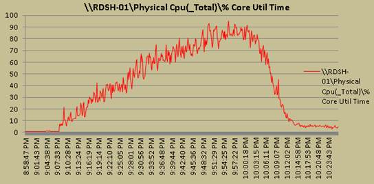
Figure 99 RDS Host Memory Utilization
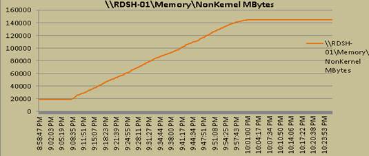
Figure 100 RDS Host Network Utilization
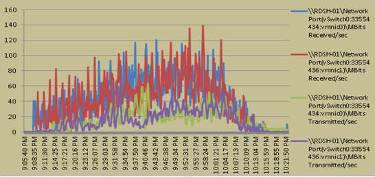
Figure 101 RDS Host Adapter Utilization
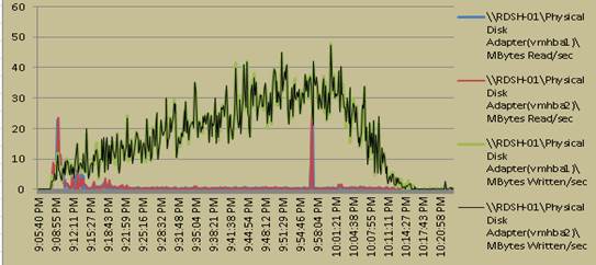
RDSH Host ESXTOP Charts (Host-2)
Figure 102 RDS Host CPU Utilization
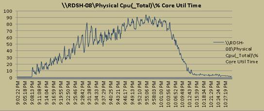
Figure 103 RDS Host Memory Utilization
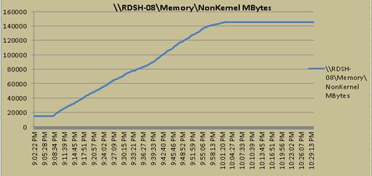
Figure 104 RDS Host Network Utilization
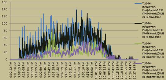
Figure 105 RDS Host Adapter Utilization
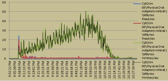
CPU Core Util% for RDSH Cluster Test with 2100 Users for all ESXi Hosts
Figure 106 ESXi-Host-RDSH01
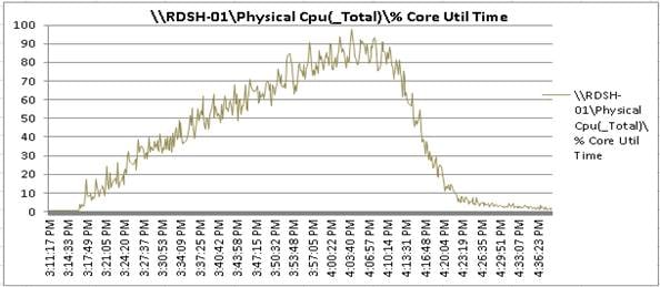
Figure 107 ESXi-Host-RDSH02
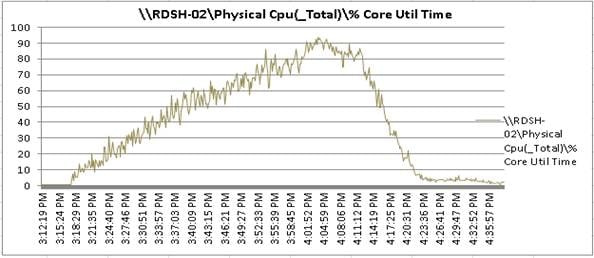
Figure 108 ESXi-Host-RDSH03
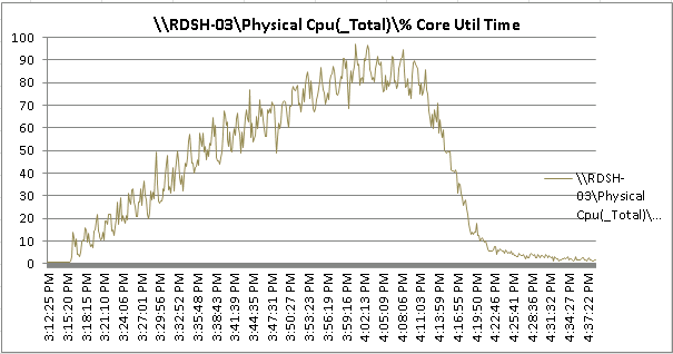
Figure 109 ESXi-Host-RDSH04
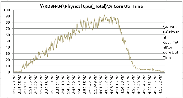
Figure 110 ESXi-Host-RDSH05
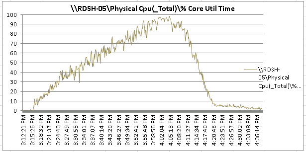
Figure 111 ESXi-Host-RDSH06
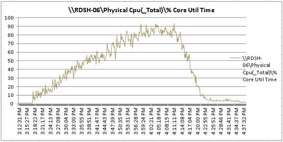
Figure 112 ESXi-Host-RDSH07
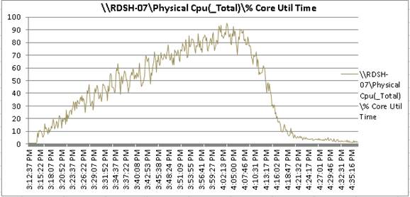
Figure 113 ESXi-Host-RDSH08
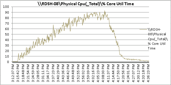
Figure 114 ESXi-Host-RDSH09
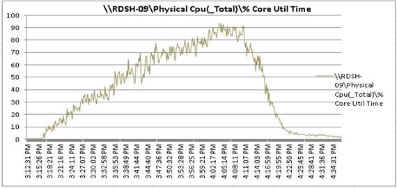
Figure 115 ESXi-Host-RDSH10
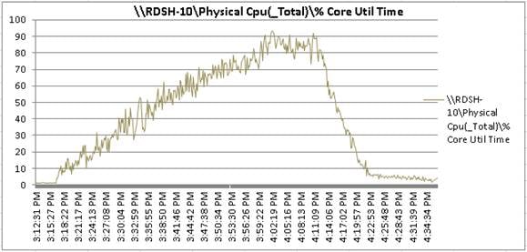
2100 Users RDSH Cluster Test IBM FlashSystem A9000 Storage Metrics
Figure 116 IBM FlashSystem A9000 Storage graphs for Latency , bandwidth and IOPS for 2100 Users RDSH Cluster Test
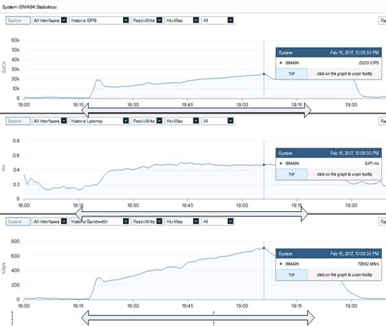
Simulation 2: 2900 Windows 10 x64 Non-Persistent VMware Horizon Cluster Test
VDI HOST Metrics for 2900 VDI Users
Figure 117 VDI Host CPU Utilization
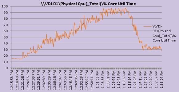
Figure 118 VDI Host Memory Utilization
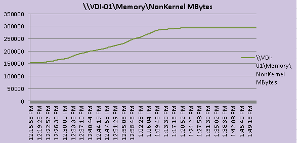
Figure 119 VDI Host Network Utilization
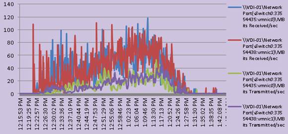
Figure 120 VDI Host Adapter Utilization
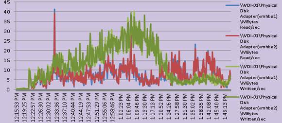
Sample VDI Host ESXTOP Chart (Host-2)
Figure 121 VDI Host CPU Utilization
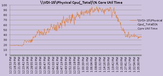
Figure 122 VDI Host Memory Utilization
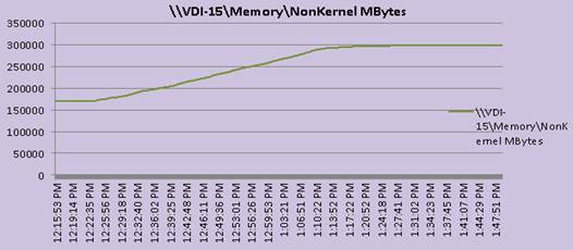
Figure 123 VDI Host Network Utilization
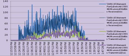
Figure 124 VDI Host Adapter Utilization
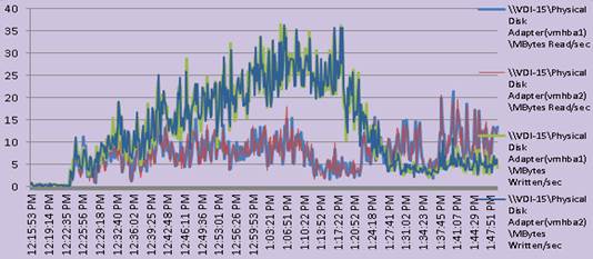
Figure 125 Storage Charts for 2900 Users VDI Cluster Test
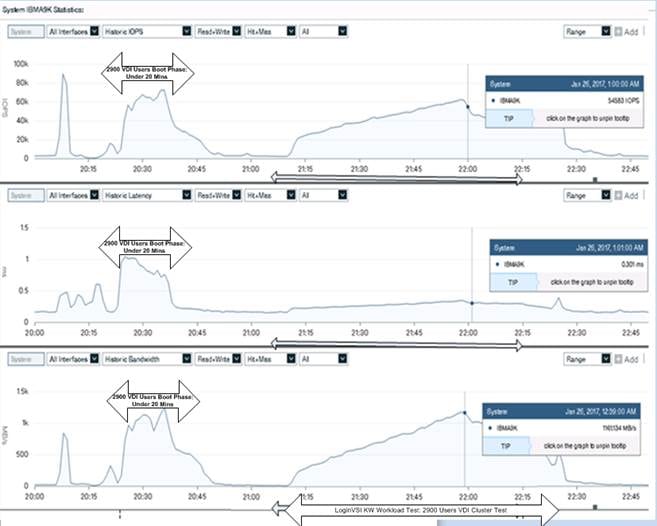
ESXi Host CPU Util% for All Hosts: VDI Cluster Test with 2900 Users
Figure 126 ESXi Host VDI-01
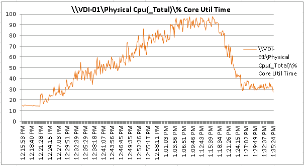
Figure 127 ESXi Host VDI-02

Figure 128 ESXi Host VDI-03
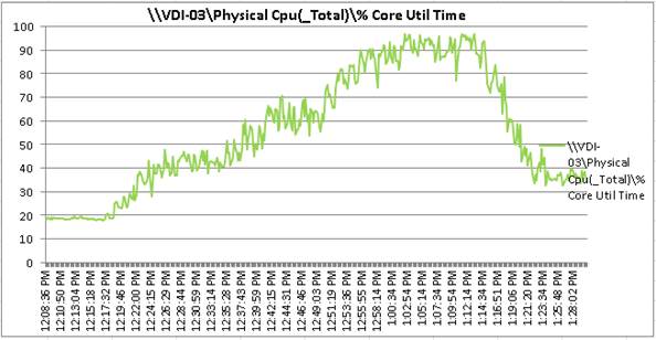
Figure 129 ESXi Host VDI-04
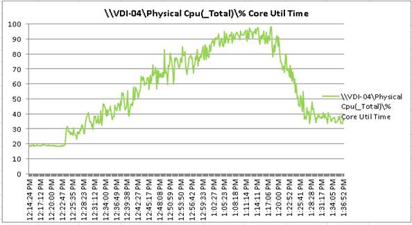
Figure 130 ESXi Host VDI-05
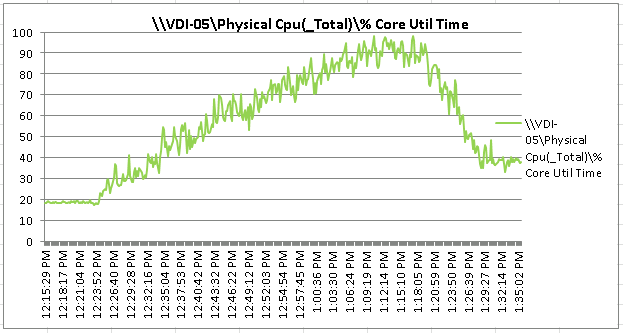
Figure 131 ESXi Host VDI-06
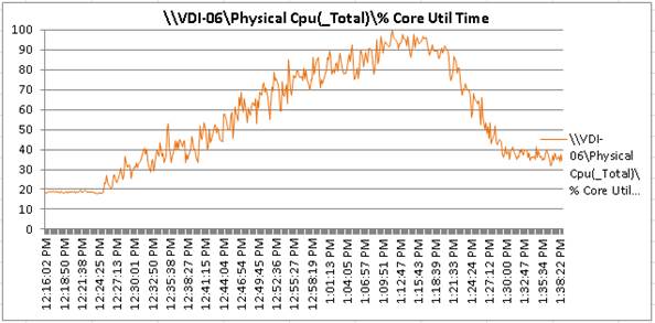
Figure 132 ESXi Host VDI-07
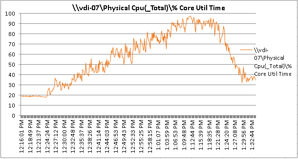
Figure 133 ESXi Host VDI-08
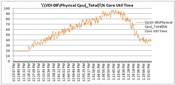
Figure 134 ESXi Host VDI-09
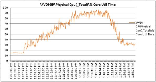
Figure 135 ESXi Host VDI-10
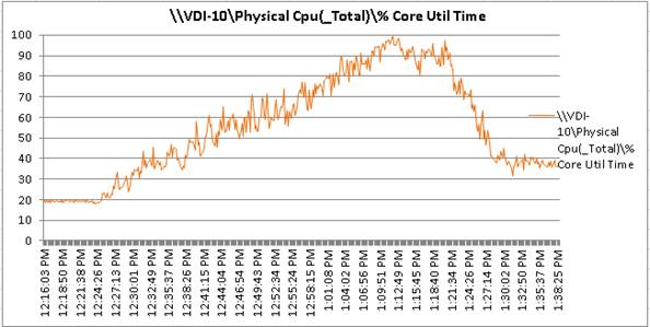
Figure 136 ESXi Host VDI-11
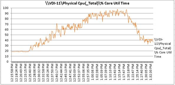
Figure 137 ESXi Host VDI-12
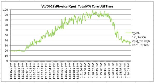
Figure 138 ESXi Host VDI-13
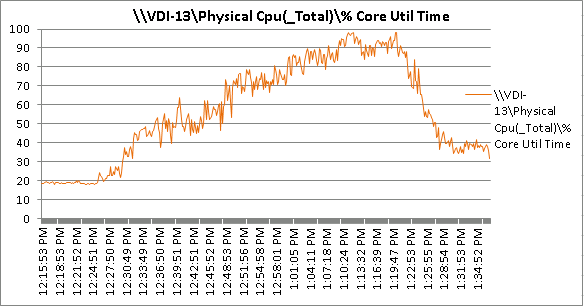
Figure 139 ESXi Host VDI-14
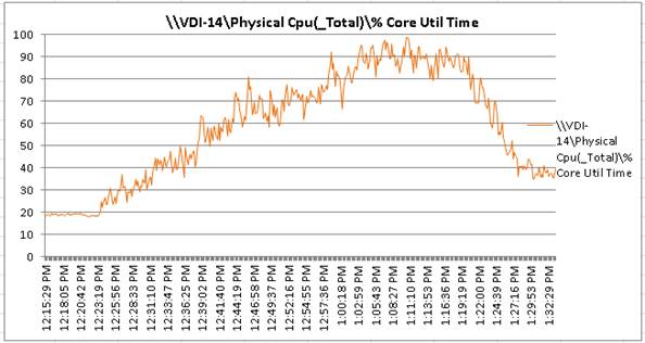
Figure 140 ESXi Host VDI-15
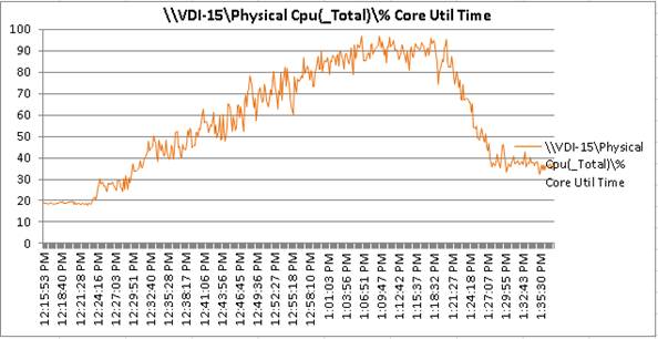
Figure 141 ESXi Host VDI-16
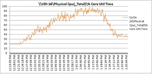
Figure 142 ESXi Host VDI-17
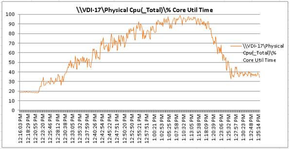
Figure 143 ESXi Host VDI-18
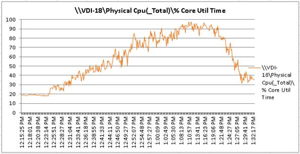
Figure 144 ESXi Host VDI-19
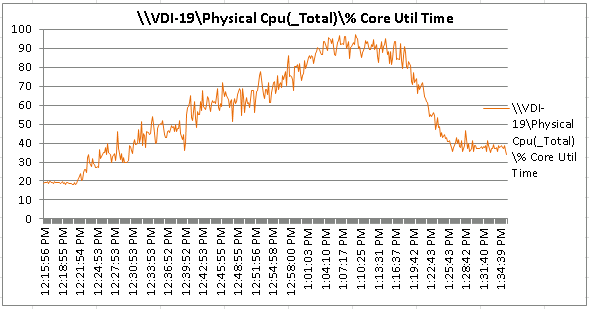
Figure 145 ESXi Host VDI-20
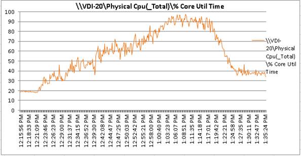
5000 Mixed Workload VMware Horizon RDSH and VDI Linked Clone Virtual Machines Testing (Combination of Scenarios 1 and 2)
Sample RDSH Host Metrics
Figure 146 RDSH Host CPU Utilization
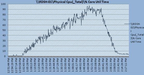
Figure 147 RDSH Host Memory Utilization
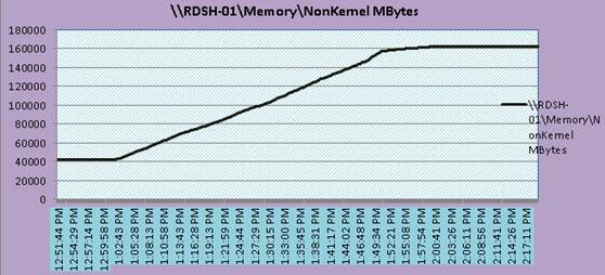
Figure 148 RDSH Host Network Utilization
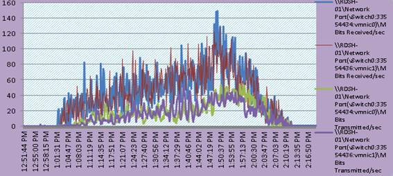
Figure 149 RDSH Host Adapter Utilization
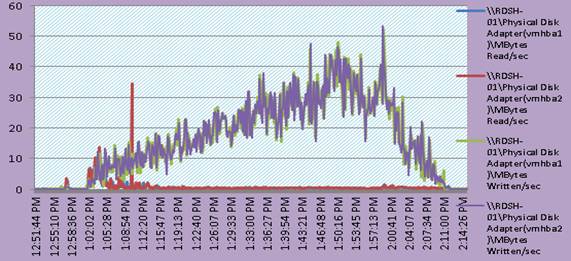
ESX CPU Util% for All RDSH Hosts on 5000 Users Scale Test
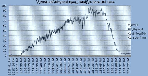
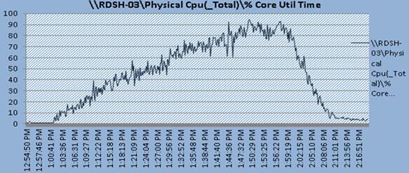
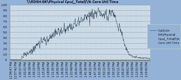
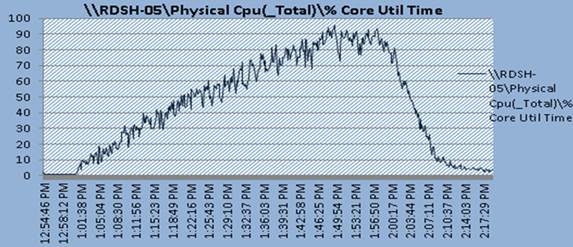
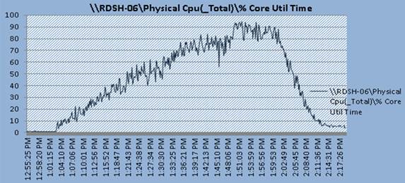
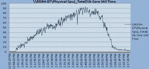
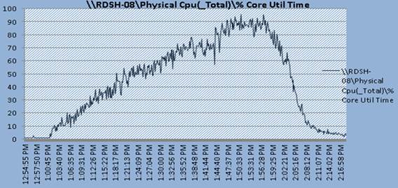
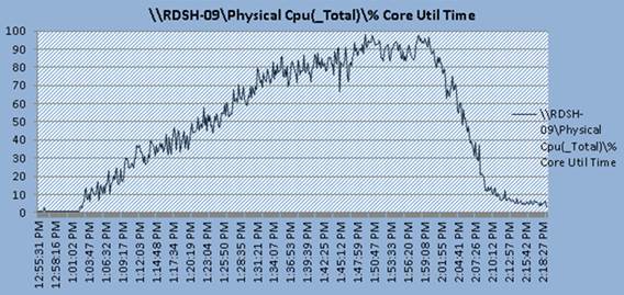
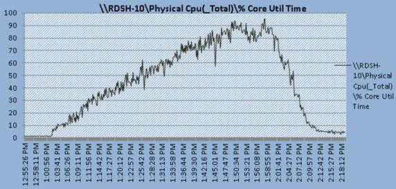
Sample RDS Servers Perfmon Metrics for 5000 Users Mixed Scale Test
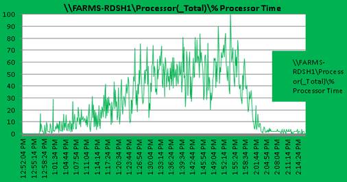
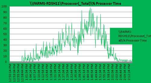
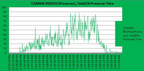
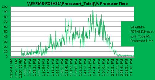
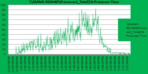
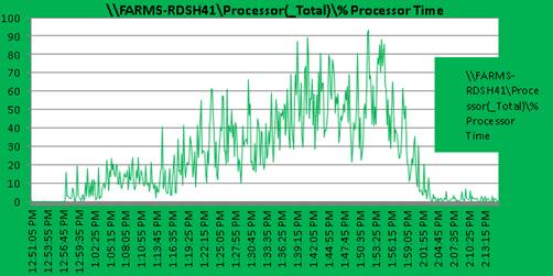
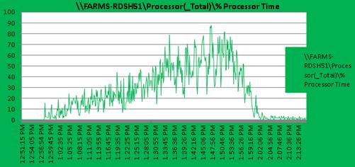
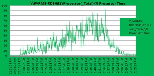
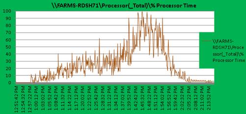
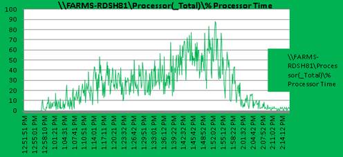
Sample VDI Host Metrics for 5000 Users Scale Test
Figure 150 VDI Host CPU Utilization VDI
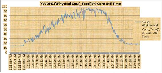
Figure 151 VDI Host Memory Utilization
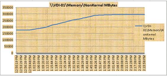
Figure 152 VDI Host Network Utilization
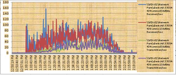
Figure 153 VDI Host Adapter Utilization
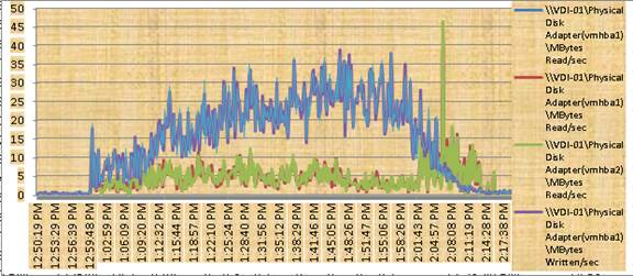
Figure 154 VDI Host CPU Utilization (Host 2)
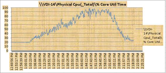
Figure 155 VDI Host Memory Utilization
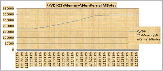
Figure 156 VDI Host Network Utilization
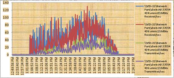
Figure 157 VDI Host Adapter Utilization
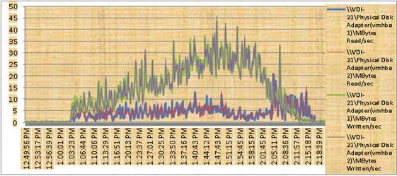
ESXTOP Util% Charts for All VDI Hosts
Figure 158 VDI Host-03
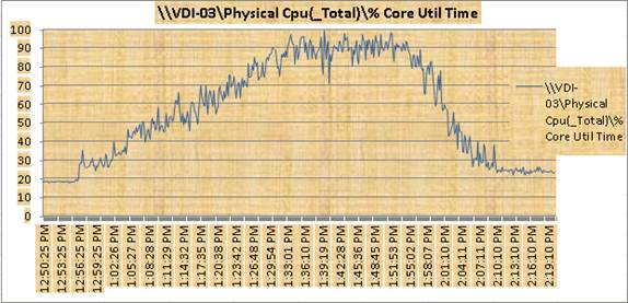
Figure 159 VDI Host--04
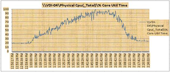
Figure 160 VDI Host--05
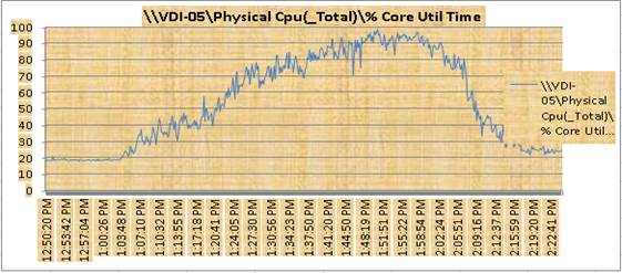
Figure 161 VDI Host--06
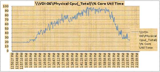
Figure 162 VDI-07
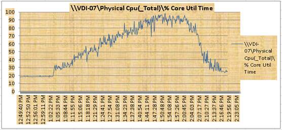
Figure 163 VDI Host--08
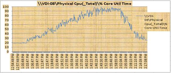
Figure 164 VDI Host--09
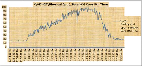
Figure 165 VDI Host--10
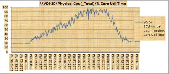
Figure 166 VDI Host--11
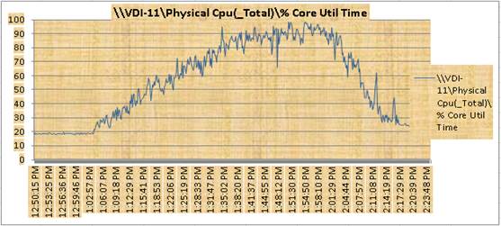
Figure 167 VDI Host-12
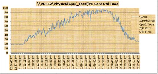
Figure 168 VDI Host-13
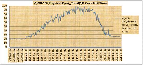
Figure 169 VDI Host-14
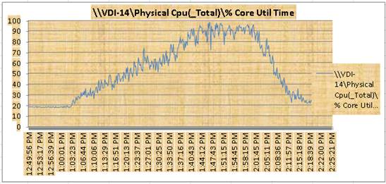
Figure 170 VDI Host-15
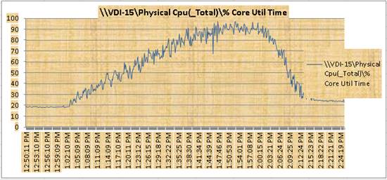
Figure 171 VDI Host-16
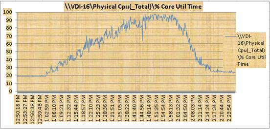
Figure 172 VDI Host-17
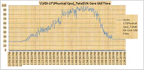
Figure 173 VDI Host -18
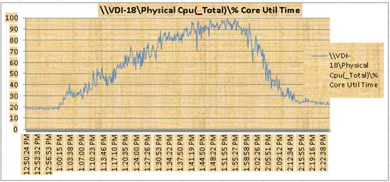
Figure 174 VDI Host-19
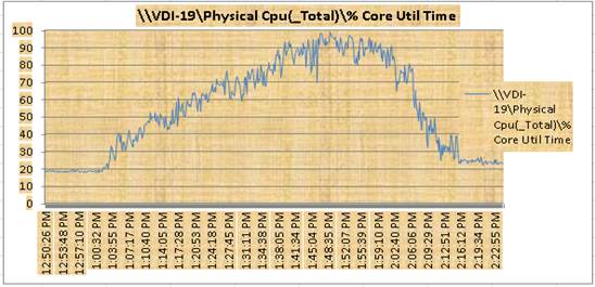
Figure 175 VDI Host-20
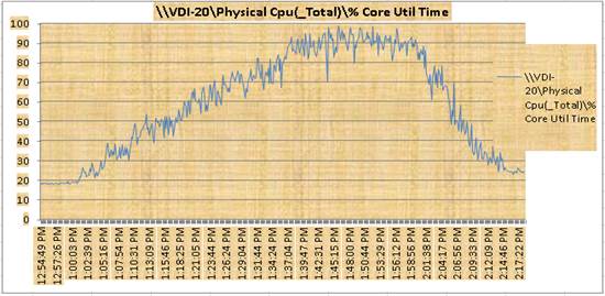
IBM A9000 Storage Charts for 5000 Users Scale Test
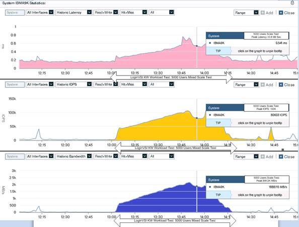
5000 Users Mixed Scale Test Boot Phase (Sample metrics: 2 RDS Hosts and 4 VDI Hosts)
RDSH Host ESXTOP Chart for Boot Phase: 5000 Users Mixed Users Workload
Figure 176 RDS Host-02
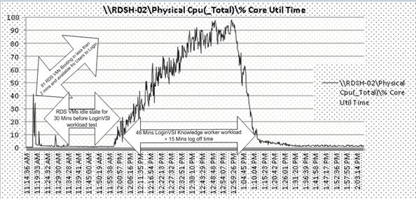
Figure 177 RDS Host-10
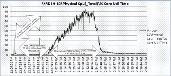
VDI Host ESXTOP Chart for Boot Phase: 5000 Users Mixed Users Workload
Figure 178 VDI Host04
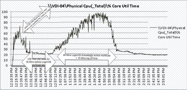
Figure 179 VDI Host-12
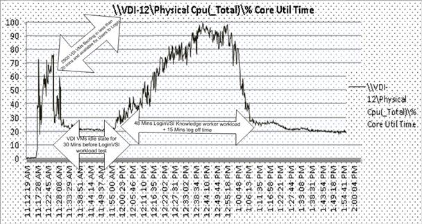
Figure 180 VDI Host-14
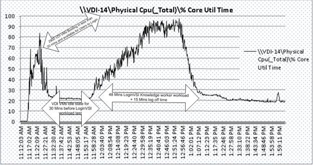
Figure 181 VDI Host-20
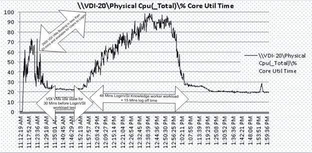
 Feedback