VersaStack Solutions with Red Hat OpenShift Container Platform 4.3 and IBM FlashSystem Family
Available Languages
Bias-Free Language
The documentation set for this product strives to use bias-free language. For the purposes of this documentation set, bias-free is defined as language that does not imply discrimination based on age, disability, gender, racial identity, ethnic identity, sexual orientation, socioeconomic status, and intersectionality. Exceptions may be present in the documentation due to language that is hardcoded in the user interfaces of the product software, language used based on RFP documentation, or language that is used by a referenced third-party product. Learn more about how Cisco is using Inclusive Language.
- US/Canada 800-553-2447
- Worldwide Support Phone Numbers
- All Tools
 Feedback
 Feedback

VersaStack Solutions with Red Hat OpenShift Container Platform 4.3 and IBM FlashSystem Family
Design and Deployment Guide for VersaStack User Provisioned Infrastructure for Red Hat OpenShift Container Platform with Cisco UCS, Cisco ACI, IBM FlashSystem Family, and VMware vSphere 6.7U3
Published: June 2020

In partnership with:
![]()
About the Cisco Validated Design Program
The Cisco Validated Design (CVD) program consists of systems and solutions designed, tested, and documented to facilitate faster, more reliable, and more predictable customer deployments. For more information, go to:
http://www.cisco.com/go/designzone.
ALL DESIGNS, SPECIFICATIONS, STATEMENTS, INFORMATION, AND RECOMMENDATIONS (COLLECTIVELY, "DESIGNS") IN THIS MANUAL ARE PRESENTED "AS IS," WITH ALL FAULTS. CISCO AND ITS SUPPLIERS DISCLAIM ALL WARRANTIES, INCLUDING, WITHOUT LIMITATION, THE WARRANTY OF MERCHANTABILITY, FITNESS FOR A PARTICULAR PURPOSE AND NONINFRINGEMENT OR ARISING FROM A COURSE OF DEALING, USAGE, OR TRADE PRACTICE. IN NO EVENT SHALL CISCO OR ITS SUPPLIERS BE LIABLE FOR ANY INDIRECT, SPECIAL, CONSEQUENTIAL, OR INCIDENTAL DAMAGES, INCLUDING, WITHOUT LIMITATION, LOST PROFITS OR LOSS OR DAMAGE TO DATA ARISING OUT OF THE USE OR INABILITY TO USE THE DESIGNS, EVEN IF CISCO OR ITS SUPPLIERS HAVE BEEN ADVISED OF THE POSSIBILITY OF SUCH DAMAGES.
THE DESIGNS ARE SUBJECT TO CHANGE WITHOUT NOTICE. USERS ARE SOLELY RESPONSIBLE FOR THEIR APPLICATION OF THE DESIGNS. THE DESIGNS DO NOT CONSTITUTE THE TECHNICAL OR OTHER PROFESSIONAL ADVICE OF CISCO, ITS SUPPLIERS OR PARTNERS. USERS SHOULD CONSULT THEIR OWN TECHNICAL ADVISORS BEFORE IMPLEMENTING THE DESIGNS. RESULTS MAY VARY DEPENDING ON FACTORS NOT TESTED BY CISCO.
CCDE, CCENT, Cisco Eos, Cisco Lumin, Cisco Nexus, Cisco StadiumVision, Cisco TelePresence, Cisco WebEx, the Cisco logo, DCE, and Welcome to the Human Network are trademarks; Changing the Way We Work, Live, Play, and Learn and Cisco Store are service marks; and Access Registrar, Aironet, AsyncOS, Bringing the Meeting To You, Catalyst, CCDA, CCDP, CCIE, CCIP, CCNA, CCNP, CCSP, CCVP, Cisco, the Cisco Certified Internetwork Expert logo, Cisco IOS, Cisco Press, Cisco Systems, Cisco Systems Capital, the Cisco Systems logo, Cisco Unified Computing System (Cisco UCS), Cisco UCS B-Series Blade Servers, Cisco UCS C-Series Rack Servers, Cisco UCS S-Series Storage Servers, Cisco UCS Manager, Cisco UCS Management Software, Cisco Unified Fabric, Cisco Application Centric Infrastructure, Cisco Nexus 9000 Series, Cisco Nexus 7000 Series. Cisco Prime Data Center Network Manager, Cisco NX-OS Software, Cisco MDS Series, Cisco Unity, Collaboration Without Limitation, EtherFast, EtherSwitch, Event Center, Fast Step, Follow Me Browsing, FormShare, GigaDrive, HomeLink, Internet Quotient, IOS, iPhone, iQuick Study, LightStream, Linksys, MediaTone, MeetingPlace, MeetingPlace Chime Sound, MGX, Networkers, Networking Academy, Network Registrar, PCNow, PIX, PowerPanels, ProConnect, ScriptShare, SenderBase, SMARTnet, Spectrum Expert, StackWise, The Fastest Way to Increase Your Internet Quotient, TransPath, WebEx, and the WebEx logo are registered trademarks of Cisco Systems, Inc. and/or its affiliates in the United States and certain other countries.
All other trademarks mentioned in this document or website are the property of their respective owners. The use of the word partner does not imply a partnership relationship between Cisco and any other company. (0809R)
© 2020 Cisco Systems, Inc. All rights reserved.
Table of Contents
Application Modernization and Enterprise Applications
Cisco Unified Computing System
Cisco UCS Fabric Interconnects
Cisco UCS 5108 Blade Server Chassis
Cisco UCS 2408 Fabric Extender
Cisco UCS B-Series Blade Servers
Cisco UCS C-Series Rack Servers
Cisco UCS Virtual Interface Card 1400
2nd Generation Intel® Xeon® Scalable Processors
Cisco Workload Optimization Manager (optional)
Cisco Application Centric Infrastructure and Nexus Switching
IBM Spectrum Virtualize for IBM FlashSystems 9200, 7200 and 5100
IBM FlashSystem 9200, 7200 and 5100 high availability
Data Protection on FlashSystem 9200, 7200, and 5100
IBM FlashSystem Family Overview
FlashSystem Features for Manageability
VersaStack for Red Hat OpenShift Container Platform Add-on Components
Red Hat OpenShift Container Platform
IBM CSI Driver for Block Storage
VersaStack with OCP Logical Topology
VersaStack Network Connectivity and Design
Application Centric Infrastructure Design
IBM FlashSystem– iSCSI Connectivity
VersaStack Compute Connectivity
Cisco UCS Server Configuration for VMware vSphere
Virtual Switching Architecture
Red Hat OpenShift Container Platform Architecture
OpenShift Ingress and Egress Traffic flow
OpenShift internal cluster communication with OpenShift SDN
OpenShift External Cluster Communication
Red Hat OpenShift Container Platform Deployment on VersaStack
OpenShift Cluster Node connectivity on VersaStack
VersaStack Storage Design for OCP
Deployment Hardware and Software
VersaStack Storage Configuration
FlashSystem 7200 Storage System – Management Access
Storage Controllers and Storage Pool Configuration
Network Configuration of the IBM FlashSystem
VersaStack Network Configuration
Create an OCP Application Tenant with the Cisco ACI APIC
Create Application Profile for OpenShift Container Platform
VersaStack VMware vSphere Configuration
Setting Up vSphere Distributed Resource Scheduler (DRS) Rules
OpenShift Container Platform Installation and Configuration
Prerequisites and Preparation Stage
OCP Network Connectivity Requirements
Red Hat OpenShift Container Platform 4.3 Installation Overview
Install Infrastructure Services
Installing and Configuring a DNS server (named)
Installing and Configuring a DHCP Server (dhcp)
Installing and Configuring a Web Server (Apache httpd)
Installing and Configuring the Load Balancer (haproxy)
Generating an SSH Private Key and Adding It to the Agent
Obtaining the Installation Program
Create the Installation Configuration File
Installing and Creating the Ignition Configuration Files on Mgmt-host
Installing the CLI by Downloading the Binary
Prepare the Terraform Installer
Approving the CSRs for Your Machines (Optional)
IBM CSI Driver Installation and Configuration
Preparing the IBM FlashSystem Backend Storage
Configuring Worker Nodes Running Red Hat Enterprise Linux CoreOS
Install IBM Block Storage CSI Driver on Red Hat OpenShift Container Platform
Creating a Test Persistent Volume Claim (PVC)
Applications Deployment on VersaStack for OpenShift Container Platform
Deploy Applications using OpenShift Operator
Red Hat OpenShift Container Platform Day-2 Operations
VersaStack Infrastructure Validation
IBM CSI Block Storage Driver Validation
Red Hat OpenShift Container Platform Environment Validation
OpenShift Container Platform Benchmarking with Ripsaw
IBM Cloud Pak for Applications
IBM Cloud Pak for Multi-cloud Management
Accelerate Application Modernization
To help organizations with their digital transformation and to enhance their cloud-native and application modernization practices, Cisco and IBM have partnered to produce this Cisco Validated Design (CVD) for the VersaStack™ user provisioned infrastructure for Red Hat OpenShift Container Platform solution, featuring the IBM FlashSystem family.
VersaStack™ Solutions bring together a comprehensive set of converged infrastructure and software-defined technologies from IBM and Cisco designed for quick deployment and rapid time to value. The solution includes Cisco UCS integrated infrastructure together with IBM’s simplified, distributed storage portfolio to deliver extraordinary levels of agility and efficiency. Combining Red Hat OpenShift with VersaStack™ helps achieve the speed, flexibility, security and scale required for application modernization and digital transformation initiatives. It also improves efficiency, and delivers better data protection, lower risk, and the flexibility to scale this highly available enterprise-grade infrastructure stack to accommodate new business requirements and other changes over time. For many organizations, this means adopting micro-services and DevOps practices and moving away from monolithic application development practices as a first step in creating more business value from their applications.
This CVD supports all products in the IBM FlashSystem family, delivering both hybrid and all-flash options, and running on IBM Spectrum Virtualize software – a common data management software layer enabling hybrid and multi-cloud deployments. The FlashSystem family products are all NVMe-enabled, with performance and scalability that spans entry enterprise/midrange enterprise to high-end enterprise level clients.
IBM FlashSystem storage is enabled for Red Hat® OpenShift® Container Platform deployments through CSI Plug-Ins. Red Hat® OpenShift®, an enterprise-ready Kubernetes container platform with full-stack automated operations to manage hybrid cloud and multi-cloud deployments, is optimized to improve developer productivity and promote innovation. Red Hat OpenShift includes everything needed for hybrid cloud, enterprise container and Kubernetes development and deployments. It includes an enterprise-grade Linux® operating system, container runtime, networking, monitoring, container registry, authentication, and authorization solutions.
This document provides a reference architecture that includes design and deployment guidance, best practices, and other recommendations. With this guide, one can simplify the digital transformation and address many of the associated challenges, including cost and risk reduction, scalability, operational flexibility, and security.
Businesses are increasingly expecting technology to be a centerpiece of every new change. Traditional approaches to leverage technology are too slow in delivering innovation at the pace at which business ecosystems are changing.
Furthermore, there is a rapid industry transition underway. With most organizations now using a mix of cloud models and more than one public cloud provider, and billions of US dollars expected to be spent in 2020 on hybrid multi-cloud infrastructure, hybrid multi-cloud is the new normal - and it is impacting strategic storage and infrastructure choices.
In order to keep up with new technologies or stay one step ahead, enterprises will have to overcome key challenges to accelerate product development, add value and compete better at lower cost.
To succeed, organizations must adopt new technologies, such as the cloud, by updating existing IT infrastructure to accommodate new requirements, including those related to, hybrid cloud and multi-cloud environments, security and data privacy. They must implement new processes and methodologies such as DevOps and micro-services, and they need to address gaps in their current available skill sets.
One observation that is worth unpacking is that the speed of Hybrid Multi-cloud adoption is being driven by the idea that developers can build once and deploy anywhere, freeing them to innovate with speed and agility. Open innovations like Linux and Java were aimed at this goal and each spawned entire industries. VMware made it possible to move virtual machines from one x86 platform to another. Today, however, we've reached an apex with container technology such as Red Hat OpenShift Container Platform.
The need to move fast along the digital transformation path leaves organizations with very little room for errors when making decisions about their infrastructure and its related services. The speed of transformation further increases the exposure to risks associated with any changes.
Even though cloud-based services can accelerate the digital transformation that customers are seeking, using public cloud-based services exclusively can be difficult, and a complete transition might take a significant amount of time. In some cases, it is simply not possible because of regulations or other constraints related to data sensitivity, privacy, and security.
Solution
The VersaStack™ user provisioned infrastructure for Red Hat OpenShift platform solution, featuring IBM FlashSystem addresses many of these challenges because it allows organizations to move faster with less risk. This solution provides more flexibility and options for managing, operating, and scaling IT infrastructures along the digital transformation journey, while operating in a predictable and economical cost structure.
Figure 1 Solution
The VersaStack for Red Hat® Openshift® Container Platform solution covered in this Cisco Validated Design (CVD) is a converged infrastructure (CI) stack featuring IBM FlashSystem storage. Red Hat® Openshift® Container Platform is a platform for developing and running containerized applications. It is designed to allow applications and the data centers that support them to expand from just a few machines and applications to thousands of machines that serve millions of clients.
The converged infrastructure stack is comprised of Cisco compute and network switches, an IBM FlashSystem family storage and VMware vSphere as the underlying hypervisor used as User Provisioned Infrastructure (UPI) for OpenShift Container Platform (OCP). This stack is integrated so customers do not have to allocate time and resources researching the required components and how to optimally integrate them to support OCP. This CI solution was also tested and validated, which saves time and minimizes risks so that you can quickly deploy the solution, become productive in days, and focus on your business rather than worrying about setting up infrastructure.
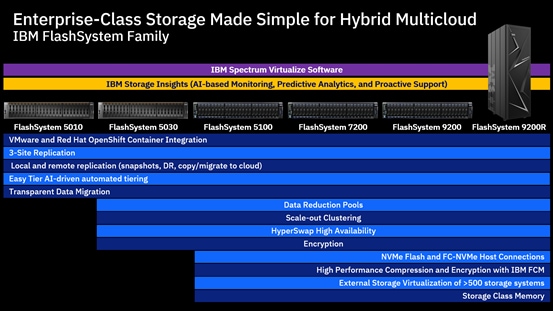
All the products in the IBM FlashSystem family are supported as part of this CVD. The FlashSystem family simplifies storage for hybrid multi-cloud. With a unified set of software, tools and API’s, the flash storage platform addresses the entire range of storage needs, all from one data platform that extends enterprise functionality across the storage estate:
· IBM FlashSystem 5010, 5030, and 5100 deliver Entry Enterprise solutions
· FlashSystem 7200 provides a Midrange Enterprise solution
· FlashSystem 9200 and the rack-based FlashSystem 9200R deliver two high end enterprise solutions.
All of these systems are based on IBM Spectrum Virtualize software, the common storage software used in this solution. When the software is enhanced, it is enhanced across the entire product family.
The IBM FlashSystem family delivers excellent performance coupled with a wealth of enterprise features. The majority of these FlashSystem models support both all-flash and hybrid configurations, denoted by ”H” in the model name. This flexibility enables you to build a system that is economically targeted to meet your specific needs.
IBM FlashSystem storage integration in this CVD is based on Container Storage Interface (CSI) Driver for IBM block storage systems, which enables container orchestrators such as Kubernetes to manage the life cycle of persistent storage.
Another key aspect of the solution is minimizing risks by providing more flexibility. VersaStack is a highly flexible and scalable CI platform that is based on a unified architecture. With VersaStack, you can start small and grow as your business needs grow.
Introduction
The featured VersaStack user provisioned infrastructure for OpenShift Container platform solution is a pre-designed, integrated, and validated architecture for the data center that combines Cisco UCS servers, the Cisco Nexus family of switches, and IBM FlashSystem family storage with IBM Spectrum Virtualize software into a single, flexible architecture. VersaStack is designed for high availability (HA), with no single point of failure, while maintaining cost-effectiveness and flexibility in the design to support a wide variety of workloads. The VersaStack solution covered in this document is for Red Hat OpenShift Container Platform (OCP), built on Enterprise Kubernetes for an on-premises deployment.
The VersaStack for OpenShift Container Platform solution, in addition to the hardware components, includes VMware vSphere as the hypervisor layer on top of which the OpenShift Container Platform components are deployed.
Integration between OpenShift Container Platform and the storage and data management services occur at several levels, all of which are captured in the design aspects of this document. The main storage integration is based on Container Storage Interface (CSI) Driver for IBM block storage systems, which enables container orchestrators such as Kubernetes to manage the life cycle of persistent storage.
After CSI driver is installed, it becomes part of the Kubernetes framework, which helps accelerates development and complements DevOps practices.
The OCP platform is installed on top of a VMware cluster with the OCP nodes running as Red Hat Enterprise Linux CoreOS (RHCOS) VMs on ESXi hosts which are in turn deployed on the Cisco UCS servers.
The following design and deployment aspects of the VersaStack for OCP solution are explained in this document:
· Red Hat OpenShift Container Platform 4.3
· VersaStack converged infrastructure
· VMware vSphere 6.7 U3
· IBM CSI driver – Dynamic storage provisioner for OpenShift
· IBM FlashSystem Family storage featuring IBM Spectrum Virtualize
The document also covers key configurations based on the validated environment and best practices.
Audience
The intended audience for this document includes, but is not limited to, DevOps managers, IT infrastructure managers, application development leaders, business digital transformation leaders, storage and data management managers, sales engineer and architects working with hybrid and private clouds, and other parties that are looking for a tested, market-proven CI solution that offers flexibility and simplicity in support of their cloud native and application modernization needs along with their digital transformation journey.
Purpose of This Document
The purpose of this design and deployment guide is to provide a reference architecture with specific examples indicating how the solution was designed, deployed, and tested. In addition, the document provides several best practices and recommendations that simplify your implementation of this solution.
What’s New?
Although the VersaStack for OCP solution was developed based on an existing CVD (VersaStack with Cisco ACI and IBM FlashSystem family), the following elements distinguish this version of VersaStack from previously published solutions:
· Support for Red Hat OpenShift Container Platform 4.3.
· IIBM CSI block storage driver integration with OpenShift Kubernetes for dynamic persistent storage provisioning for applications.
· Cisco 2408 Fabric Extender providing 25 Gbps connectivity from the Cisco UCS Chassis to Cisco UCS Fabric Interconnects
· Support for the Cisco UCS release 4.1(1a)
· Support for ACI 4.2 (4i)
· IBM FlashSystem storage, built with IBM Spectrum Virtualize software, version 8.3.1
For more information about previous VersaStack designs, see: https://www.cisco.com/c/en/us/solutions/data-center-virtualization/versastack-solution-cisco-ibm/index.html
Solution Summary
This solution includes a hardware stack from Cisco and IBM, a hypervisor from VMware, and OCP software platform from Red Hat, a set of tools for integration and management, and a collection of containerized applications available via Red Hat and IBM Catalogs. These components are integrated so that customers can deploy the solution quickly and economically while eliminating many of the risks associated with researching, designing, building, and deploying similar solutions from the ground up.
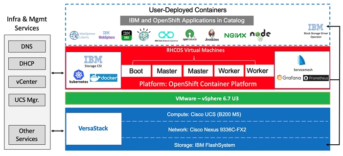
Figure 2 VersaStack UPI for OpenShift Container Platform
Solution Benefits
Successful digital transformation requires solution that provides software, processes, and systems together in a digital-ready infrastructure that is simple, intelligent, automated, and highly secure.
VersaStack combined with the OCP platform provides faster deployment, higher efficiency, a highly scalable and flexible stack, and less risk. These intrinsic capabilities improve developer productivity, reduce build times, and optimize storage with advanced data management capabilities. The solution helps VersaStack customers to modernize existing applications, develop new cloud-native solutions, and leverage cloud-based services.
OpenShift Container Platform helps customers accelerate their digital transformation because it contains all the required tools needed out-of-the-box for consuming on-premises, cloud-based services.
IBM FlashSystem storage, built with IBM Spectrum Virtualize software, is targeted for hybrid multi-cloud solutions and enterprise deployments. Storage Class Memory (SCM) and IBM FlashCore technology bring the performance needed for demanding workloads and AI-driven Easy Tier ensures data is effortlessly positioned on the right storage tier for the right workload.
IBM FlashCore Modules bring unprecedented levels of efficiency with as much as 4PB of data in only 2 rack units. 3-site replication, including replication to the cloud, and improved scalability and data reduction in the cloud transform hybrid multi-cloud deployments and lower critical costs.
Red Hat OpenShift pushes the boundaries of what containers and Kubernetes can do for developers, driving innovation for stateful applications, serverless or event-driven applications, and machine learning. The platform integrates tightly with Jenkins and other standard continuous integration continuous delivery (CI/CD) tools for security-focused application builds. Red Hat OpenShift helps you build with speed, agility, confidence, and choice so that developers can get back to doing work that matters.
In addition, IBM offers a family of Cloud Paks that give developers, data managers and administrators an open environment to quickly build new cloud-native applications, modernize/extend existing applications, and deploy middleware in a consistent manner across multiple clouds.
Beyond the well-integrated software stack at the OCP platform level, VersaStack offer the same value at the hardware stack level.
This joint solution offers the following benefits:
· Highly available, scalable platform and flexible architecture supports various deployment models
· Accelerated adoption of new technology to modernize heritage applications and cloud native development
· A trusted platform from industry leaders, Cisco and IBM Enterprise-grade, highly available infrastructure stack
· Converged infrastructure validated for OCP with a published CVD that includes best practices and recommendations, which minimizes risks and accelerates development cycles
· IBM FlashSystems with new roll-out of FlashCore Modules (FCMs). The innovation behind these custom-designed modules delivers improved performance, capacity, and reliability.
· The enterprise-class functionality of IBM Spectrum Virtualize software including: Encryption, Copy Services such as Synchronous and Asynchronous Mirroring, Deduplication, Compression, Virtualization of over 500 different storage devices, single pain of glass management, EasyTier, among others.
· Ecosystem of partners and the recognized and trusted VersaStack brand
· Cooperative support between Red Hat, Cisco, IBM, and VMware
· Easy to deploy, consume, and manage; saves time and resources on research, procurement, and integration
· Flexible and highly scalable architecture with outstanding application performance
· Integration with Kubernetes for dynamic provisioning of persistent storage services with advanced data management capabilities
· Enhanced CI/CD workflow and practices associated with DevOps and micro-services
Solution Components
The solution offers redundant architecture from a compute, network, and storage perspective. The solution consists of the following key components:
· Cisco UCS 6400 Series Fabric Interconnects (FI)
· Cisco UCS 5108 Blade Server chassis
· Cisco Unified Computing System (Cisco UCS) servers with 2nd generation Intel Xeon scalable processors
· Cisco Nexus 9336C-FX2 Switches running ACI mode
· IBM FlashSystem NVMe-accelerated Storage
· VMware vSphere 6.7 Update 3
· OpenShift Container Platform 4.3
· IBM block storage CSI driver 1.1.0
Use Cases
The Red Hat OpenShift Container Platform gives developers a self-service platform on which to build and run containerized applications. With Red Hat OpenShift you can quickly start creating new cloud-native applications or cloud-enabling existing applications and spawning an environment for a new microservice in minutes.
Cloud-Native, Application Modernization and a model of hosting additional services such as enterprise applications are covered as use cases in this document, the solution supports many other use cases which are not documented in this guide. These use cases reflect the flexibility of the VersaStack platform to accommodate various requirements and enable the different workloads and topologies you might focus on.
Customers can optionally consider IBM Cloud Paks for their application needs, IBM Cloud Paks are pre-integrated containers, pre-packaged solutions, ready for deployment in production environments. These IBM Cloud Paks can be easily deployed to Kubernetes-based container orchestration platforms. They are software solutions that give clients an open, faster, and more secure way than individual solutions to move core business applications to any cloud. Designed to reduce development time, IBM Cloud Paks include IBM middleware and common software services for development and management, on top of a standard integration layer. They are portable and can run on-premises, on public clouds, or in an integrated system.
IBM currently offers five independent Cloud Paks that provides a Kubernetes environment to help to build cloud-native applications or modernize the existing applications. Also, IBM Cloud Paks enable you to quickly bring workloads to an integrated container platform, supporting production-level qualities of service and end-to-end lifecycle management.
![]() For more information on IBM Cloud Paks, refer to the Appendix of this document. However, customers interested in IBM Cloud Paks should refer to the IBM documentation for the installation and usage details or contact IBM or their partners for proper recommendations and guidance.
For more information on IBM Cloud Paks, refer to the Appendix of this document. However, customers interested in IBM Cloud Paks should refer to the IBM documentation for the installation and usage details or contact IBM or their partners for proper recommendations and guidance.
Cloud-Native
In a cloud-native environment, applications are viewed as collections of microservices with many deployable components that deploy at various speeds and independently of each other. Manually deploying anything becomes an unsustainable effort prone to error, inconsistency, and delays. Automating continuous delivery pipelines is a way to help operations from deploying an application they have little knowledge of and rescue developers from complex configurations and deployments. Efficient delivery means more time for innovation, enabling the business to disrupt the market and competitors.
OCP is cloud-native ready out-of-the-box. No additional software packages or tools are required, but you can add to the platform-containerized applications with Red Hat tools. Through automation, self-service, and containerization, Red Hat development platforms let you deliver apps on any architecture faster. With Red Hat open tools, you can migrate your infrastructure and become cloud-native at your own pace, without rebuilding from the ground up.
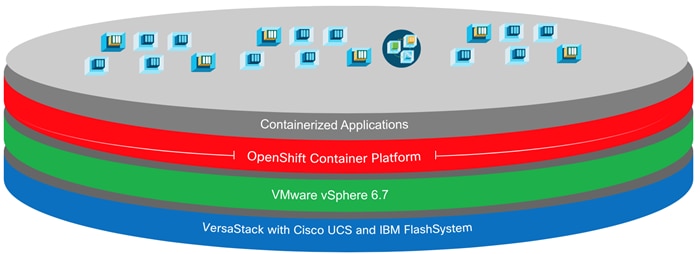
Figure 3 illustrates a high-level overview of the VersaStack for OCP platform with the cloud-native use case.
Figure 3 VersaStack UPI for OCP – Cloud Native Topology
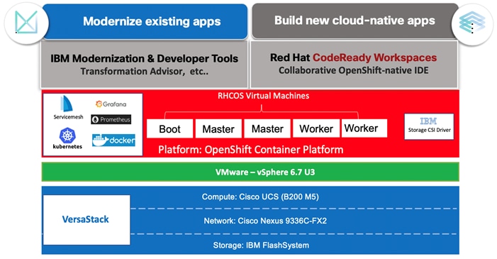
Application Modernization and Enterprise Applications
Application modernization is key for enterprises in moving towards cloud-based infrastructure and services, application modernization is a strategy for helping companies to move legacy application footprint to the cloud-based infrastructure such as OpenShift Container Platform.
Applications need to be adapted and ported to the new infrastructure using Cloud-native technologies, such as containers, Kubernetes, and microservices.
VersaStack for OCP supports enterprise applications in several ways. VersaStack offers hybrid virtualized architecture by combining virtualization for both traditional Virtual machines and containers. It is also easy to integrate the VersaStack platform with the existing on-premises infrastructure for consistent management of the entire end-to-end infrastructure. With many customers already having enterprise and middleware applications deployed, prior to introducing containers to their environment and some needing a platform that can support legacy and modernized components of an application, having the VersaStack infrastructure is like a perfect recipe for application modernization.
Customers commonly add new applications and tools to the VersaStack OCP platform and also want to integrate with products that are already in place. For example, the organization might use a database deployed in traditional form and might prefer to keep this database in place and allow the containerized applications running within the OCP platform to interact with the database. They might also use other middleware products, for example; IBM offers containerized versions of many of its enterprise applications, including MQ, WebSphere, and several products in the Db2 family. However, some organizations might not deploy these products in their container version and might start with a more traditional approach of hosting the application on a guest OS running as a VM, and in some cases the application may end up being deployed directly on the server (bare metal); VersaStack can be extended to host these applications as well (Figure 4).
Figure 4 Hosting Enterprise Applications on VersaStack for OCP
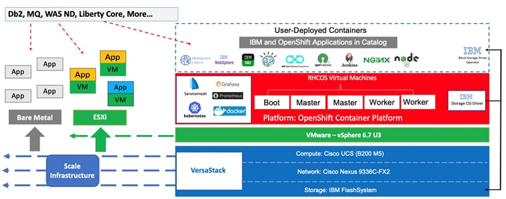
Additional workloads and applications beyond OCP can be hosted on the VersaStack CI platform. This deployment model can also accommodate IBM enterprise applications that can run on a VM as part of the vSphere environment or in a bare metal fashion directly on the Cisco UCS servers if they are not containerized. The flexibility of the platform to scale improves ROI and other aspects of productivity and, in addition, offers customers more confidence that the platform supports their changing needs over time.
Regarding application modernization, each customer develops their own plan for transforming monolithic applications to a cloud-native topology and the process can be very complex. Therefore, a reliable, flexible, and scalable platform at the infrastructure level that complements the value proposition of the OCP software platform can have tremendous value.
The VersaStack architecture is comprised of the following infrastructure components for compute, network, and storage:
· Cisco Unified Computing System (Cisco UCS)
· Cisco Nexus and Cisco MDS Switches
· IBM SAN Volume Controller and IBM FlashSystem storage
These components are connected and configured according to best practices of both Cisco and IBM and provide an ideal platform for running a variety of workloads with confidence.
The VersaStack reference architecture explained in this document leverages:
· Cisco UCS 6400 Series Fabric Interconnects (FI)
· Cisco UCS 5108 Blade Server chassis
· Cisco Unified Computing System servers with 2nd generation Intel Xeon scalable processors
· Cisco Nexus 9336C-FX2 Switches running ACI mode
· IBM FlashSystem NVMe-accelerated Storage
· VMware vSphere 6.7 Update 3
· Red Hat OpenShift Container Platform (version 4.3)
· IBM Container Storage Interface (CSI) for block storage (version 1.1.0)
Figure 5 VersaStack for OpenShift Container Platform – Components
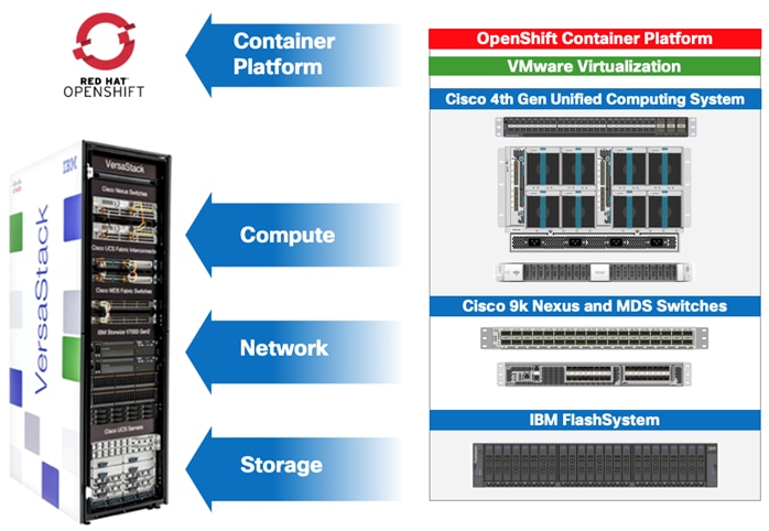
The following sections provide a technical overview of the compute, network, storage and management components of the VersaStack solution.
Cisco Unified Computing System
Cisco Unified Computing System (Cisco UCS) is a next-generation data center platform that integrates computing, networking, storage access, and virtualization resources into a cohesive system designed to reduce total cost of ownership (TCO) and to increase business agility. The system integrates a low-latency; lossless unified network fabric with enterprise-class, x86-architecture servers. The system is an integrated, scalable, multi-chassis platform where all resources are managed through a unified management domain.
The Cisco Unified Computing System consists of the following subsystems:
· Compute - The compute piece of the system incorporates servers based on latest Intel’s x86 processors. Servers are available in blade and rack form factor, managed by Cisco UCS Manager.
· Network - The integrated network fabric in the system provides a low-latency, lossless, 10/25/40/100 Gbps Ether-net fabric. Networks for LAN, SAN and management access are consolidated within the fabric. The unified fabric uses the innovative Single Connect technology to lowers costs by reducing the number of network adapters, switches, and cables. This in turn lowers the power and cooling needs of the system.
· Storage access - Cisco UCS system provides consolidated access to both SAN storage and Network Attached Storage over the unified fabric. This provides customers with storage choices and investment protection. The use of Policies, Pools, and Profiles allows for simplified storage connectivity management.
· Management - The system uniquely integrates compute, network and storage access subsystems, enabling it to be managed as a single entity through Cisco UCS Manager software. Cisco UCS Manager increases IT staff productivity by enabling storage, network, and server administrators to collaborate on Service Profiles that define the desired server configurations.
Cisco UCS Management
Cisco UCS® Manager (UCSM) provides unified, integrated management for all software and hardware components in Cisco UCS. UCSM manages, controls, and administers multiple blades and chassis enabling administrators to manage the entire Cisco Unified Computing System as a single logical entity through an intuitive GUI, a CLI, as well as a robust API. Cisco UCS Manager is embedded into the Cisco UCS Fabric Interconnects and offers comprehensive set of XML API for third party application integration.
Cisco Intersight (optional)
The Cisco Intersight™ platform provides intelligent cloud-powered infrastructure management for Cisco Unified Computing System™ (Cisco UCS®) and Cisco HyperFlex™ platforms. Cisco Intersight is a subscription-based, cloud service for infrastructure management that simplifies operations by providing pro-active, actionable intelligence for operations. Cisco Intersight provides capabilities such as Cisco Technical Assistance Center (TAC) integration for support and Cisco Hardware Compatibility List (HCL) integration for compliance that Enterprises can leverage for all their Cisco HyperFlex and Cisco UCS systems in all locations. Cloud-based delivery enables Enterprises to quickly adopt the new features that are continuously being rolled out in Cisco Intersight.
Each Cisco UCS server or Cisco HyperFlex system automatically includes a Cisco Intersight Base edition at no additional cost when the customer accesses the Cisco Intersight portal and claims the device. In addition, customers can purchase the Cisco Intersight Essentials edition using the Cisco ordering tool.
A view of the unified dashboard provided by Intersight can be seen in Figure 6.
Figure 6 Cisco Intersight Dashboard View
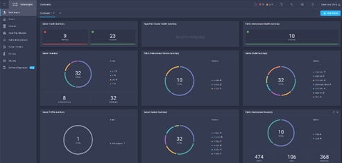
For more information on Cisco Intersight, see: https://www.intersight.com/help/getting_started#cisco_intersight_overview
Cisco UCS Fabric Interconnects
The Cisco UCS Fabric Interconnects (FIs) provide a single point for connectivity and management for the entire Cisco Unified Computing System. Typically deployed as an active-active pair, the system’s fabric interconnects integrate all components into a single, highly available management domain controlled by the Cisco UCS Manager. Cisco UCS FIs provide a single unified fabric for the system that supports LAN, SAN and management traffic using a single set of cables.
The 4th generation (6454) Fabric Interconnect (Figure 7) leveraged in this VersaStack design provides both network connectivity and management capabilities for the Cisco UCS system. The Cisco UCS 6454 offers line-rate, low-latency, lossless 10/25/40/100 Gigabit Ethernet, Fibre Channel over Ethernet (FCoE), and 32 Gigabit Fibre Channel functions.
Figure 7 Cisco UCS 6454 Fabric Interconnect
![]()
Cisco UCS 5108 Blade Server Chassis
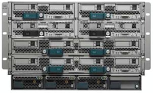
The Cisco UCS 5108 Blade Server Chassis (Figure 8) delivers a scalable and flexible blade server architecture. The Cisco UCS blade server chassis uses an innovative unified fabric with fabric-extender technology to lower total cost of ownership by reducing the number of network interface cards (NICs), host bus adapters (HBAs), switches, and cables that need to be managed. Cisco UCS 5108 is a 6-RU chassis that can house up to 8 half-width or 4 full-width Cisco UCS B-Series Blade Servers. A passive mid-plane provides up to 80Gbps of I/O bandwidth per server slot and up to 160Gbps for two slots (full-width). The rear of the chassis contains two I/O bays to house Cisco UCS Fabric Extenders for enabling uplink connectivity to the pair of FIs for both redundancy and bandwidth aggregation.
Figure 8 Cisco UCS 5108 Blade Server Chassis
|
|
|
Cisco UCS 2408 Fabric Extender
The Cisco UCS 2408 Fabric Extender has eight 25-Gigabit Ethernet, FCoE-capable, Small Form-Factor Pluggable (SFP28) ports that connect the blade chassis to the fabric interconnect. Each Cisco UCS 2408 provide 10-Gigabit Ethernet ports connected through the midplane to each half-width slot in the chassis, giving it a total 32 10G interfaces to Cisco UCS blades. Typically configured in pairs for redundancy, two fabric extenders provide up to 400 Gbps of I/O from FI 6454's to 5108 chassis.
Figure 9 Cisco UCS 2408 Fabric Extender

Cisco UCS B-Series Blade Servers
Cisco UCS B-Series Blade Servers are based on Intel Xeon processors; they work with virtualized and non-virtualized applications to increase performance, energy efficiency, flexibility, and administrator productivity. The latest Cisco UCS M5 B-Series blade server models come in two form factors; the half-width Cisco UCS B200 Blade Server and the full-width Cisco UCS B480 Blade Server. Cisco UCS M5 server uses the latest Intel Xeon Scalable processors with up to 28 cores per processor. The Cisco UCS B200 M5 blade server supports 2 sockets, 3TB of RAM (using 24 x128GB DIMMs), 2 drives (SSD, HDD or NVMe), 2 GPUs and 80Gbps of total I/O to each server. The Cisco UCS B480 blade is a 4-socket system offering 6TB of memory, 4 drives, 4 GPUs and 160 Gb aggregate I/O bandwidth.
The Cisco UCS B200 M5 Blade Server (Figure 10) has been used in this VersaStack architecture.
Figure 10 Cisco UCS B200 M5 Blade Server

Each supports the Cisco UCS VIC 1400 series adapters to provide connectivity to the unified fabric.
For more information about Cisco UCS B-series servers, see: https://www.cisco.com/c/en/us/products/collateral/servers-unified-computing/ucs-b-series-blade-servers/datasheet-c78-739296.html
Cisco UCS C-Series Rack Servers
Cisco UCS C-Series Rack Servers deliver unified computing in an industry-standard form factor to reduce TCO and increase agility. Each server addresses varying workload challenges through a balance of processing, memory, I/O, and internal storage resources. The most recent M5 based Cisco UCS C-Series rack mount models come in three main models; the Cisco UCS C220 1RU, the Cisco UCS C240 2RU, and the Cisco UCS C480 4RU chassis, with options within these models to allow for differing local drive types and GPUs.
The enterprise-class Cisco UCS C220 M5 Rack Server (Figure 11) has been leveraged in this VersaStack design.
Figure 11 Cisco UCS C220 M5 LFF Server
![]()
For more information about Cisco UCS C-series servers, see:
Cisco UCS Virtual Interface Card 1400
The Cisco UCS Virtual Interface Card (VIC) 1400 Series provides complete programmability of the Cisco UCS I/O infrastructure by presenting virtual NICs (vNICs) as well as virtual HBAs (vHBAs) from the same adapter according to the provisioning specifications within UCSM.
The Cisco UCS VIC 1440 is a dual-port 40-Gbps or dual 4x 10-Gbps Ethernet/FCoE capable modular LAN On Motherboard (mLOM) adapter designed exclusively for the M5 generation of Cisco UCS B-Series Blade Servers. When used in combination with an optional port expander, the Cisco UCS VIC 1440 capabilities are enabled for two ports of 40-Gbps Ethernet. In this CVD, Cisco UCS B200 M5 blade servers were equipped with Cisco VIC 1440.
The Cisco UCS VIC 1457 is a quad-port Small Form-Factor Pluggable (SFP28) mLOM card designed for the M5 generation of Cisco UCS C-Series Rack Servers. The card supports 10/25-Gbps Ethernet or FCoE. The card can present PCIe standards-compliant interfaces to the host, and these can be dynamically configured as either NICs or HBAs. In this CVD, Cisco VIC 1457 was installed in Cisco UCS C240 M5 server.
2nd Generation Intel® Xeon® Scalable Processors
This VersaStack architecture includes the 2nd generation Intel Xeon Scalable processors in all the Cisco UCS M5 server models used in this design. These processors provide a foundation for powerful data center platforms with an evolutionary leap in agility and scalability. Disruptive by design, this innovative processor family supports new levels of platform convergence and capabilities across computing, storage, memory, network, and security resources.
Cascade Lake (CLX-SP) is the code name for the next-generation Intel Xeon Scalable processor family that is supported on the Purley platform serving as the successor to Skylake SP. These chips support up to eight-way multiprocessing, use up to 28 cores, incorporate a new AVX512 x86 extension for neural-network and deep-learning workloads, and introduce persistent memory support. Cascade Lake SP–based chips are manufactured in an enhanced 14-nanometer (14-nm++) process and use the Lewisburg chip set.
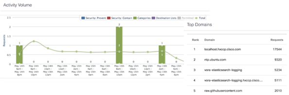
Cisco Umbrella (optional)
Cisco Umbrella is the delivery of secure DNS through Cisco’s acquisition of OpenDNS. Cisco Umbrella stops malware before it can get a foothold by using predictive intelligence to identify threats that next-generation firewalls might miss. Implementation is easy as pointing to Umbrella DNS servers, and unobtrusive to the user base outside of identified threat locations they may have been steered to. In addition to threat prevention, Umbrella provides detailed traffic utilization as shown in Figure 12.
Figure 12 Traffic Breakdown of Activity Seen through Cisco Umbrella
For more information about Cisco Umbrella, see: https://www.cisco.com/c/dam/en/us/products/collateral/security/router-security/opendns-product-overview.pdf
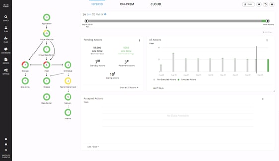
Cisco Workload Optimization Manager (optional)
Instantly scale resources up or down in response to changing demand assuring workload performance. Drive up utilization and workload density. Reduce costs with accurate sizing and forecasting of future capacity.
To perform intelligent workload management, Cisco Workload Optimization Manager (CWOM) models your environment as a market of buyers and sellers linked together in a supply chain. This supply chain represents the flow of resources from the datacenter, through the physical tiers of your environment, into the virtual tier and out to the cloud. By managing relationships between these buyers and sellers, CWOM provides closed-loop management of resources, from the datacenter, through to the application.
When you launch CWOM, the Home Page provides the following options:
· Planning
· Placement
· Reports
· Overall Dashboard
The CWOM dashboard provides views specific to On-Prem, the Cloud, or a Hybrid view of infrastructure, applications, and costs across both.
Figure 13 CWOM Dashboard
For more information about the full capabilities of workload optimization, planning, and reporting, see: https://www.cisco.com/c/en/us/products/servers-unified-computing/workload-optimization-manager/index.html
Cisco Application Centric Infrastructure and Nexus Switching
Cisco ACI is an evolutionary leap from SDN’s initial vision of operational efficiency through network agility and programmability. Cisco ACI has industry leading innovations in management automation, programmatic policies, and dynamic workload provisioning. The ACI fabric accomplishes this with a combination of hardware, policy-based control systems, and closely coupled software to provide advantages not possible in other architectures.
Cisco ACI takes a policy-based, systems approach to operationalizing the data center network. The policy is centered around the needs (reachability, access to services, security policies) of the applications. Cisco ACI delivers a resilient fabric to satisfy today's dynamic applications.
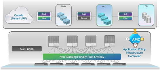
Cisco ACI Architecture
The Cisco ACI fabric is a leaf-and-spine architecture where every leaf connects to every spine using high-speed 40/100-Gbps Ethernet links, with no direct connections between spine nodes or leaf nodes. The ACI fabric is a routed fabric with a VXLAN overlay network, where every leaf is VXLAN Tunnel Endpoint (VTEP). Cisco ACI provides both Layer 2 (L2) and Layer 3 (L3) forwarding across this routed fabric infrastructure.
Figure 14 Cisco ACI High-Level Architecture
Cisco Nexus 9000 Series Switches
The Cisco ACI fabric is built on a network of Cisco Nexus 9000 series switches that provide low-latency, high-bandwidth connectivity with industry proven protocols and innovative technologies to create a flexible, scalable, and highly available architecture. ACI is supported on several models of Nexus 9000 series switches and line cards. The selection of a Nexus 9000 series switch as an ACI spine or leaf switch will depend on a number of factors such as physical layer connectivity (1/10/25/40/50/100-Gbps), FEX aggregation support, analytics support in hardware (Cloud ASICs), FCoE support, link-level encryption, support for the Multi-Pod, Multi-Site design implementations and so on.
Architectural Building Blocks
The key architectural buildings blocks of the Cisco ACI fabric are:
· Application Policy Infrastructure Controller (APIC) - Cisco APIC is the unifying point of control in Cisco ACI for automating and managing the end-to-end data center fabric. The Cisco ACI fabric is built on a network of individual components that are provisioned and managed as a single entity. The APIC is a physical appliance that serves as a software controller for the overall fabric. It is based on Cisco UCS C-series rack mount servers with 2x10Gbps links for dual-homed connectivity to a pair of leaf switches and 1Gbps interfaces for out-of-band management.
· Spine Nodes – The spines provide high-speed (40/100-Gbps) connectivity between leaf nodes. The ACI fabric forwards traffic by doing a host lookup in a mapping database that contains information about the leaf node where an endpoint (IP, Mac) resides. All known endpoints are maintained in a hardware database on the spine switches. The number of endpoints or the size of the database is a key factor in the choice of a Nexus 9000 model as a spine switch. Leaf switches also maintain a database but only for those hosts that send/receive traffic through it.
The Cisco Nexus featured in this design for the ACI spine is the Nexus 9364C implemented in ACI mode (Figure 15).
![]()
For more information about Cisco Nexus 9364C switch, see: https://www.cisco.com/c/en/us/products/switches/nexus-9364c-switch/index.html
· Leaf Nodes – Leaf switches are essentially Top-of-Rack (ToR) switches that end devices connect into. They provide Ethernet connectivity to devices such as servers, firewalls, storage and other network elements. Leaf switches provide access layer functions such as traffic classification, policy enforcement, L2/L3 forwarding of edge traffic etc. The criteria for selecting a specific Nexus 9000 model as a leaf switch will be different from that of a spine switch.
The Cisco Nexus featured in this design for the ACI leaf is the Nexus 9336C-FX2 implemented in ACI mode (Figure 16).
![]()
For more information about Cisco Nexus 9336C-FX2 switch, see: https://www.cisco.com/c/en/us/products/switches/nexus-9336c-fx2-switch/index.html
For more information about Cisco ACI, see: https://www.cisco.com/c/en/us/products/cloud-systemsmanagement/application-policy-infrastructure-controller-apic/index.html
IBM Spectrum Virtualize
IBM Spectrum Virtualize is a software-enabled storage virtualization engine that provides a single point of control for storage resources within the data centers. IBM Spectrum Virtualize is a core software engine of well-established and industry-proven IBM storage virtualization solutions. These solutions include IBM SAN Volume Controller and all versions of IBM Storwize and FlashSystem family of products.
The IBM Spectrum Virtualize™ software stack was first introduced as a part of the IBM SAN Volume Controller (SVC) product released in 2003, offering unparalleled storage virtualization capabilities before being integrated into the IBM Storwize platform and more recently, a subset of the IBM FlashSystem storage appliances.
Since the first release of IBM SAN Volume Controller, IBM Spectrum Virtualize has evolved into the feature-rich storage hypervisor evolving over 34 major software releases, installed and deployed on over 250,000+ Storwize and 70,000 SVC engines. Managing 5000,000 enclosures, virtualizing, managing and securing 9.6 Exabytes of data. Exceeding 99.999% availability.
This solution supports IBM Spectrum Virtualize firmware version 8.3.1 and any* IBM FlashSystem storage array such as the following:
· IBM FlashSystem 9200
· IBM FlashSystem 7200
· IBM FlashSystem 5100
*The interoperability and configuration steps are consistent between the members of the FlashSystem family.
For reference, the IBM Storwize platforms have been replaced by the following FlashSystem product:
| Original platform |
Successor |
Drive Type |
Performance / Target Market |
| Storwize V5010 |
FlashSystem 5010 |
SAS |
Entry Enterprise |
| Storwize V5030 |
FlashSystem 5030 |
SAS |
Entry Enterprise |
| Storwize V5100 |
FlashSystem 5100 |
NVMe |
Entry Enterprise |
| Storwize V7000 Gen3 |
FlashSystem 7200 |
NVMe |
Midrange Enterprise |
| FlashSystem 9110 |
<Discontinued> |
NVMe |
N/A |
| FlashSystem 9150 |
FlashSystem 9200 |
NVMe |
High-End Enterprise |
The following are some of the new features brought in with IBM Spectrum Virtualize firmware version 8.3.1:
· Ownership groups - An ownership group defines a subset of users and objects within the system. You can create ownership groups to further restrict access to specific resources that are defined in the ownership group. Only users with Security Administrator roles can configure and manage ownership groups.
· Priority flow control - Priority flow control (PFC) is an Ethernet protocol that supports the ability to select the priority of different types of traffic within the network. With PFC, administrators can reduce network congestion by slowing or pausing certain classes of traffic on ports, thus providing better bandwidth for more important traffic. The system supports PFC on various supported Ethernet-based protocols on three types of traffic classes: system, host attachment, and storage traffic.
· Support for IBM® Easy Tier® overallocation limit for pools with IBM FlashCore Module devices as the top tier of storage.
· Support for 32GB Fibre Channel (FC) PCIe adapters.
· Support for expanding distributed arrays - Ability to dynamically expand distributed arrays to increase the available capacity of the array or create additional rebuild space. As part of the expansion, the system automatically migrates data for optimal performance for the new expanded configuration.
· Support for pool level Volume protection - prevents active volumes or host mappings from being deleted inadvertently if the system detects recent I/O activity.
· Support for SNMP protocol version 3 enhanced security features.
· Support for enhanced auditing features for syslog servers.
· Enhanced password security.
· Improvements to the terms and definitions that relate to capacity were updated.
· Support for the new Storage Class Memory (SCM) technology (Optane, 3DXP, and so on).
· 3 site replication - Limited availability at GA and subject to RPQ initially.
· Secure Drive Erase - the ability to completely erase any customer data from a NVMe or SAS SSD drive, before it’s removed from either the control or expansion enclosure.
For more information, go to the IBM Spectrum Virtualize website: http://www03.ibm.com/systems/storage/spectrum/virtualize/index.html
IBM Spectrum Virtualize for IBM FlashSystems 9200, 7200 and 5100
IBM FlashSystem 9200, 7200 and 5100 all use IBM Spectrum Virtualize™ software that combines a variety of software-defined functionality for Flash Storage to manage data such as following:
· Deduplication
· Compression
· Thin provisioning
· Easy Tier (automatic and dynamic tiering)
· Encryption for internal and virtualized external storage
· SCSI Unmap
· HyperSwap (high availability active-active)
· FlashCopy (snapshot)
· Remote data replication
IBM FlashSystem 9200, 7200 and 5100 high availability
IBM FlashSystem 9100, 9200 and 7200 are designed to offer high system and data availability with the following features:
· HyperSwap support
· Dual-active, intelligent node canisters with mirrored cache
· Dual-port flash drives with automatic drive failure detection and RAID rebuild
· Redundant hardware, including power supplies and fans
· Hot-swappable and customer replaceable components
· Automated path failover support for the data path between the server and the drives
Data Protection on FlashSystem 9200, 7200, and 5100
Data protection from NAND chip and controller failures are managed using two IBM technologies: Variable Stripe RAID (VSR) and DRAID. VSR protects failures at the IBM FlashCore modules chip level, and DRAID protects data from failure of IBM FlashCore modules and industry-standard NVMe drives.
Variable Stripe RAID
Variable Stripe RAID is a patented IBM technology that provides data protection at the page, block, or chip level. It eliminates the necessity to replace a whole flash module when a single chip or plane fails. This increases the life and endurance of flash modules and reduces considerably maintenance events throughout the life of the system.
DRAID
Distributed RAID functionality is managed by IBM Spectrum Virtualize, which enables a storage array to distribute RAID5 or RAID6 to the largest set of drives. For example, on traditional RAID5, if 8 drives were used the data was striped across 7 and the parity was on 8.
DRAID enhanced this method by specifying the stripe width and the number of drives separately. As a result, the setup still has 7 data stripes protected by a parity stripe, but the 8 drives are selected from the larger set. In addition, with distributed sparing, each drive in the array gives up some of its capacity to make a spare instead of an unused spare drive.
DRAID6
DRAID6 is advised for FS9100, 9200, 7200 and 5100 systems, and is the only allowed option from the GUI. DRAID5 is configurable using the CLI. DRAID6 creates spare space across all NVMe SSDs or FCMs on the array and, during failure, the array rebuilds data using the spare space faster than traditional RAID rebuilds.
IBM FlashSystem Family Overview
While each member of the FlashSystem family shares a common enclosure and internal architecture principles, the performance of each platform covers a wide range of application requirements.
FlashSystem 5100
Formerly known as the IBM Storwize V5100, the FlashSystem 5100 is a virtualized, software-defined storage system comprised of hardware components and a required licensed software product, IBM Spectrum Virtualize Software. All functional capabilities for FlashSystem 5100 system are provided through IBM Spectrum Virtualize software. The two models within the 5100 series, 424 and AF4 are designed to meet modern high-performance storage requirements, including ultra-low latency, cost-effectiveness, operational efficiency, and mission-critical reliability.
It is built on a flash-optimized design, with an end-to-end NVMe strategy to bring extremely low latencies to organizations of all sizes. FlashSystem 5100 model AF4 is an all-flash storage system that supports NVMe FlashCore Modules and industry-standard NVMe flash drives in the control enclosure. Model AF4 attaches to expansion enclosures Models AFF and A9F which support SAS Flash drives. FlashSystem 5100 model 424 is a hybrid storage system that supports NVMe FlashCore Modules and industry-standard flash NVMe drives in the control enclosure. Model 424 attaches to expansion enclosures models 12F, 24F, and 92F which support SAS Flash drives and SAS HDD Drives.
FlashSystem 7200
FlashSystem 7200 is an evolution of the previous generation Storwize V7000, with the same basic enclosure hardware (metalwork only) as the other members of the FlashSystem family supporting up to 24 NVMe Flash drives or FCM, with up to four SCM drives per enclosure.
One of the main differences between the previous V7000 hardware is that all six PCIe slots can be populated with Host Interface Cards (HIC) – where previously two were always reserved for a SAS expansion attachment card. You therefore now have the option of still using a SAS expansion card if you wish to expand the capacity beyond what is supported by the base 24 slots.
However, with FCM, having a maximum usable capacity (before data reduction) of 38.4 TB, the base enclosure can hold some 750TB of usable capacity, after RAID, and before data reduction. Add in the maximum FCM compression capability of 88TB per FCM, and that is over 1.5PB of effective usable capacity from hardware FCM compression alone.
Other notable updates are a base cache memory increase to 256GiB, upgradable in two stages to 1.5TiB. The CPU’s are updated to use Intel’s Cascade Lake family with 32 cores per enclosure. All PCIe slots are 16 lane Gen3 to allow full bandwidth capability to each FibreChannel 32Gbit 4 port card. Up to 24x 32Gbit ports per enclosure.
FlashSystem 9200
The FlashSystem 9200 is an evolution of the 9150 and follows the same basic principles and specifications of the 7200 with significantly more horsepower.
FlashSystem 9200 can also support up to 1.5TiB of cache but provides 64 cores per enclosure allowing for even more system throughput, particularly when making use of the advanced functions provided by the embedded Spectrum Virtualize software.
IBM FlashSystem 9200
This section describes the FlashSystem 9200 architectural components.
Integral to the IBM FlashSystem 9200 solution is the IBM FlashCore technology. The recent evolution of this technology saw the introduction of inline hardware compression and decompression with the IBM FlashSystem model AE3 enclosure.
The IBM FlashSystem 9200 system with IBM FlashCore Modules NVMe type drives features built-in hardware data compression as standard, and this data reduction is “always on”. This compression is implemented in hardware by using field-programmable gate arrays (FPGAs) within each module and a modified dynamic GZIP algorithm. With this approach, the solution can deliver the level of performance that you expect without compression, with the added benefit of better utilization of the physical storage. Compression and decompression are transparent above the IBM FlashCore Modules except for management of space. Performance is not affected and scales linearly with the number of instances.
IBM FlashSystem 9200 Control Enclosure Data Reduction Pool compression can increase the effective capacity of your flash memory up to 5x, decreasing the cost for effective capacity up to 80 percent. Data Reduction Pool supports active data, unlike other data reduction solutions.
IBM FlashSystem 9200 Control Enclosure offers several features for Data Reduction Pool compression workloads. These features include 16 Intel core processors with up to 1.536 GB of memory per control enclosure, and a built-in compression accelerator for hardware-assisted compression. In addition, the IBM FlashSystem 9200 system with IBM FlashCore Modules NVMe-type drives applies compression to any data that is not already compressed. The IBM FlashSystem 9200 system also supports the new SCM type drives. SCM is a new storage media technology that offers high endurance, high IOPS, and ultra-low latencies.
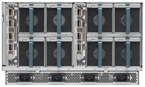
IBM FlashSystem 9200 Hardware Overview
Each FlashSystem 9200 consists of a control enclosure and IBM FlashCore module drives. The control enclosure is the storage server that runs the IBM Spectrum Virtualize software that controls and provides features to store and manage data on the IBM FlashCore module or industry-standard NVMe drives. The IBM FlashSystem 9200 system has two different types of enclosures: Control Enclosures and Expansion Enclosures.
· A Control Enclosure manages your storage systems, communicates with the host, and manages interfaces. In addition, it can also house up to 24 NVMe-capable flash drives. These drives can be either industry-standard NVMe types or the exclusive IBM FlashCore Module NVMe type and up to 4 optional SCM class drives.
· An Expansion Enclosure increases the available capacity of an IBM FlashSystem 9200 cluster. It communicates with the Control Enclosure through a dual pair of 12 Gbps serial-attached SCSI (SAS) connections. These Expansion Enclosures can house many of flash (solid-state drive (SSD)) SAS type drives, depending on which model of enclosure is ordered.
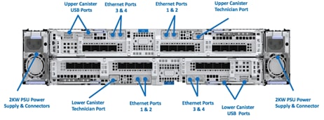
Figure 17 and Figure 18 shows the IBM FlashSystem 9200 Control Enclosure front and rear views.
Figure 17 FlashSystem 9200 Front View
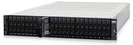
Figure 18 FlashSystem 9200 Rear View
Control Enclosures
Each Control Enclosure can have multiple attached Expansion Enclosures, which expand the available capacity of the entire system. The IBM FlashSystem 9200 solution supports up to four Control Enclosures and up to two chains of SAS Expansion Enclosures per Control Enclosure.
The IBM FlashSystem 9200 Control Enclosure supports up to 24 NVMe-capable flash drives in a 2U high form factor and consists of the following machine types:
· The 9846 has one model: AG8
· The 9848 has two models: AG8 and UG8
Expansion Enclosures
The IBM FlashSystem 9000 Expansion Enclosure consists of the following machine types:
· The 9846 has two models: AFF and A9F
· The 9848 has two models: AFF and A9F
New SAS-based small form factor (SFF) and large form factor (LFF) Expansion Enclosures support flash-only MDisks in a storage pool, which can be used for IBM Easy Tier. Consider the following points:
· IBM FlashSystem 9000 SFF Expansion Enclosure Model AFF offers drive options with SSD flash drives. Up to 480 drives of SAS expansions are supported per IBM FlashSystem 9200 Control Enclosure. The Expansion Enclosure is 2U high.
· IBM FlashSystem 9000 LFF Expansion Enclosure Model A9F offers drive options with SSD flash drives. Up to 760 drives of SAS expansions are supported per IBM FlashSystem 9200 Control Enclosure. The Expansion Enclosure is 5U high.
FlashSystem Features for Manageability
The IBM FlashSystem systems offer the following manageability and serviceability features:
· An intuitive GUI
· IBM Call-home
· IBM Storage Insights
FlashSystem Family System GUI
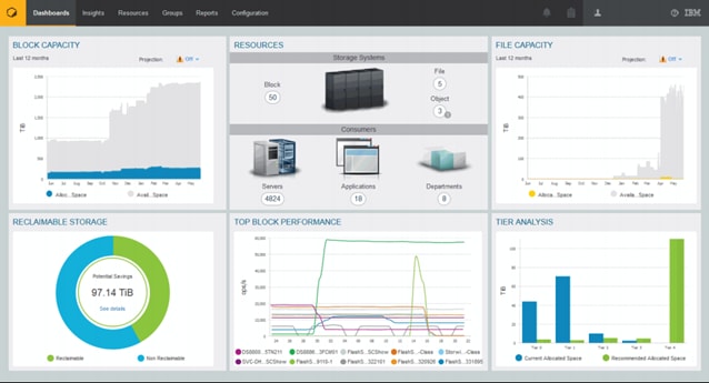
The IBM FlashSystem family systems include an easy-to-use management Spectrum Virtualize GUI that runs on one of the node canisters in the control enclosure to help you monitor, manage, and configure your system. You can access the GUI by opening any supported web browser and entering the management IP addresses. The IBM FlashSystem systems use a GUI with the same look and feel as other IBM Storwize family solutions for a consistent management experience across all platforms. The GUI has an improved overview dashboard that provides all information in an easy-to-understand format and enables visualization of effective capacity. With the GUI, you can quickly deploy storage and manage it efficiently.
Figure 19 shows the IBM FlashSystem dashboard view.
Figure 19 IBM FlashSystem GUI Dashboard
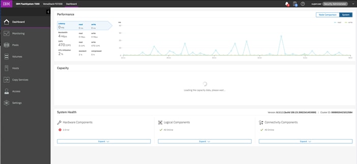
This is the default view that is displayed after the user logs on to the system. The IBM FlashSystem family systems also provides a CLI, which is useful for advanced configuration and scripting. The FlashSystem family systems support Simple Network Management Protocol (SNMP), email notifications that uses Simple Mail Transfer Protocol (SMTP), and syslog redirection for complete enterprise management access.
IBM Call Home
Call home connects the system to IBM Service Personnel who can monitor and respond to system events to ensure that your system remains up and running. The call home function opens a service alert if a serious error occurs in the system, automatically sending details of the error and contact information to IBM Service Personnel. If the system is entitled for support, a Problem Management Record (PMR) is automatically created and assigned to the appropriate IBM support team. The information provided to IBM in this case would be an excerpt from the Event Log containing the details of the error, and client contact information from the system. This enables IBM Service Personnel to contact the client and arrange service on the system, which can greatly improve the speed of resolution by removing the need for the client to detect the error and raise a Support call themselves.
IBM Storage Insights
IBM Storage Insights is an IBM Cloud software as a service offering that can help you monitor and optimize the storage resources in the system and across your data center. IBM Storage Insights monitors your storage environment and provides status about multiple systems in a single dashboard. You can view data from the perspectives of the servers, applications, and file systems. Two versions of IBM Storage Insights are available: IBM Storage Insights and IBM Storage Insights Pro.
When you order the IBM FlashSystem storage, IBM Storage Insights is available for free. With this version, you can monitor the basic health, status, and performance of various storage resources.
IBM Storage Insights Pro is a subscription-based product that provides a more comprehensive view of the performance, capacity, and health of your storage resources. In addition to the features offered by IBM Storage Insights, IBM Storage Insights Pro provides tools for intelligent capacity planning, storage reclamation, storage tiering, and performance troubleshooting services. Together, these features can help you reduce storage costs and optimize your data center.
IBM Storage Insights is a part of the monitoring and helps to ensure continued availability of the IBM FlashSystem storage.
Cloud-based IBM Storage Insights provides a single dashboard that gives you a clear view of all of your IBM block storage. You can make better decisions by seeing trends in performance and capacity. With storage health information, you can focus on areas that need attention. When IBM support is needed, IBM Storage Insights simplifies uploading logs, speeds resolution with online configuration data, and provides an overview of open tickets, all in one place.
The following features are some of those available with IBM Storage Insights:
· A unified view of IBM systems.
· IBM Storage Insights collects telemetry data and call home data and provides real-time system reporting of capacity and performance.
· Overall storage monitoring looking at the overall health of the system, monitoring of the configuration for preferred practices and system resource management.
· IBM Storage Insights provides advanced customer service with an event filter to view support tickets and automatic log collection.
Figure 20 IBM Storage Insights Dashboard
In order for IBM Storage Insights to operate, a lightweight data collector is installed in your data center to stream performance, capacity, asset, and configuration metadata to your IBM Cloud instance. The metadata flows in one direction: from your data center to IBM Cloud over HTTPS. Only metadata is collected. The actual application data that is stored on the storage systems can’t be accessed by the data collector. In the IBM Cloud, your metadata is AES256-encrypted and protected by physical, organizational, access, and security controls.
VMware vSphere 6.7 Update 3
VMware vSphere is a virtualization platform for holistically managing large collections of infrastructures (resources-CPUs, storage and networking) as a seamless, versatile, and dynamic operating environment. Unlike traditional operating systems that manage an individual machine, VMware vSphere aggregates the infrastructure of an entire data center to create a single powerhouse with resources that can be allocated quickly and dynamically to any application in need.
vSphere 6.7 Update 3 (U3) provides several improvements including, but not limited to:
· ixgben driver enhancements
· VMXNET3 enhancements
· bnxtnet driver enhancements
· QuickBoot support enhancements
· Configurable shutdown time for the sfcbd service
· NVIDIA virtual GPU (vGPU) enhancements
· New SandyBridge microcode
VersaStack for Red Hat OpenShift Container Platform Add-on Components
The following sections describe the add-on components that are part of the solution along with the core VersaStack converged infrastructure and the vSphere hypervisor. The add-on components are:
· Red Hat OpenShift Container Platform (version 4.3)
· IBM CSI driver for Block Storage, a dynamic storage provisioner for Kubernetes
Red Hat OpenShift Container Platform
Red Hat OpenShift is one of the most reliable enterprise-grade containers, designed and optimized to easily deploy web applications and services. Categorized as a cloud development Platform as a Service (PasS), OpenShift allow to developers focusing in code, taking care of all of the complex IT operations and processes.
One of its main features that OpenShift offers to the industry, is the ability to handle applications written in different languages, such as Python, Node.js, Java, and Perl.
Red Hat OpenShift is a Kubernetes distribution focused on developer experience and application security that's platform agnostic. OpenShift helps you develop and deploy applications to one or more hosts. These can be public facing web applications, or backend applications, including micro services or databases. Applications can be implemented in any programming language you choose. The only requirement is that the application can run within a container.
Additionally, OpenShift Container Platform integrate:
· Source code management, builds, and deployments for developers
· Managing and promoting images at scale as they flow through your system
· Application management at scale
· Team and user tracking for organizing an organization with tons of developers
· Networking infrastructure that supports the cluster
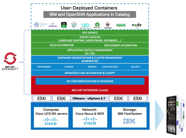
Figure 21 OpenShift Container Platform Overview
OpenShift Container Platform provides enterprise-ready enhancements to Kubernetes, including the following enhancements:
· Hybrid cloud deployments. You can deploy OpenShift Container Platform clusters to variety of public cloud platforms or in your data center.
· Integrated Red Hat technology. Major components in OpenShift Container Platform come from Red Hat Enterprise Linux and related Red Hat technologies. OpenShift Container Platform benefits from the intense testing and certification initiatives for Red Hat’s enterprise quality software.
· Open source development model. Development is completed in the open, and the source code is available from public software repositories. This open collaboration fosters rapid innovation and development.
Although Kubernetes excels at managing your applications, it does not specify or manage platform-level requirements or deployment processes. Powerful and flexible platform management tools and processes are important benefits that OpenShift Container Platform 4.3 offers. The following sections describe some unique features and benefits of OpenShift Container Platform.
Custom Operating System
OpenShift Container Platform uses Red Hat Enterprise Linux CoreOS (RHCOS), a container-oriented operating system that combines some of the best features and functions of the CoreOS and Red Hat Atomic Host operating systems. RHCOS is specifically designed for running containerized applications from OpenShift Container Platform and works with new tools to provide fast installation, Operator-based management, and simplified upgrades.
RHCOS includes:
· Ignition, which OpenShift Container Platform uses as a firstboot system configuration for initially bringing up and configuring machines.
· CRI-O, a Kubernetes native container runtime implementation that integrates closely with the operating system to deliver an efficient and optimized Kubernetes experience. CRI-O provides facilities for running, stopping, and restarting containers. It fully replaces the Docker Container Engine, which was used in OpenShift Container Platform 3.
· Kubelet, the primary node agent for Kubernetes that is responsible for launching and monitoring containers.
In OpenShift Container Platform 4.3, you must use RHCOS for all control plane machines, but you can use Red Hat Enterprise Linux (RHEL) as the operating system for compute machines, which are also known as worker machines. If you choose to use RHEL workers, you must perform more system maintenance than if you use RHCOS for all of the cluster machines.
Simplified Installation and Update Process
With OpenShift Container Platform 4.3, if you have an account with the right permissions, you can deploy a production cluster in supported clouds by running a single command and providing a few values. You can also customize your cloud installation or install your cluster in your data center if you use a supported platform.
For clusters that use RHCOS for all machines, updating, or upgrading, OpenShift Container Platform is a simple, highly automated process. Because OpenShift Container Platform completely controls the systems and services that run on each machine, including the operating system itself, from a central control plane, upgrades are designed to become automatic events. If your cluster contains RHEL worker machines, the control plane benefits from the streamlined update process, but you must perform more tasks to upgrade the RHEL machines. Our recommendation is to go with RHCOS for all the cluster nodes for automated installation of the solution and easy maintenance.
Other Key Features
Operators are both the fundamental unit of the OpenShift Container Platform 4.3 code base and a convenient way to deploy applications and software components for your applications to use. In OpenShift Container Platform, Operators serve as the platform foundation and remove the need for manual upgrades of operating systems and control plane applications. OpenShift Container Platform Operators such as the Cluster Version Operator and Machine Config Operator allow simplified, cluster-wide management of those critical components.
Operator Lifecycle Manager (OLM) and the OperatorHub provide facilities for storing and distributing Operators to people developing and deploying applications.
The Red Hat Quay Container Registry is a Quay.io container registry that serves most of the container images and Operators to OpenShift Container Platform clusters. Quay.io is a public registry version of Red Hat Quay that stores millions of images and tags.
Other enhancements to Kubernetes in OpenShift Container Platform include improvements in software defined networking (SDN), authentication, log aggregation, monitoring, and routing. OpenShift Container Platform also offers a comprehensive web console and the custom OpenShift CLI (oc) interface.
Openshift Container Platform Lifecycle
Figure 22 illustrates the basic OpenShift Container Platform lifecycle:
· Creating an OpenShift Container Platform cluster
· Managing the cluster
· Developing and deploying applications
· Scaling up applications
Figure 22 OpenShift Container Platform Lifecycle Overview
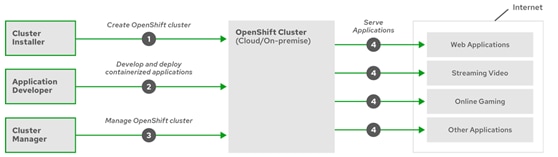
IBM CSI Driver for Block Storage
IBM block storage CSI driver is leveraged by Kubernetes persistent volumes (PVs) to dynamically provision for block storage used with stateful containers.
IBM block storage CSI driver is based on an open-source IBM project (CSI driver), included as a part of IBM storage orchestration for containers. IBM storage orchestration for containers enables enterprises to implement a modern container-driven hybrid multi-cloud environment that can reduce IT costs and enhance business agility, while continuing to derive value from existing systems.
By leveraging CSI (Container Storage Interface) drivers for IBM storage systems, Kubernetes persistent volumes (PVs) can be dynamically provisioned for block or file storage to be used with stateful containers, such as database applications (IBM Db2, MongoDB, PostgreSQL, and so on) running in Red Hat OpenShift Container Platform and/or Kubernetes clusters. Storage provisioning can be fully automatized with additional support of cluster orchestration systems to automatically deploy, scale, and manage containerized applications.
Figure 23 Integration of IBM® Block Storage Systems and CSI Driver in a Kubernetes Environment
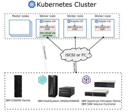
Terraform
Terraform is a tool for building, changing, and versioning infrastructure safely and efficiently. Terraform can manage existing and popular service providers as well as custom in-house solutions.
Configuration files describe to Terraform the components needed to run a single application or your entire datacenter. Terraform generates an execution plan describing what it will do to reach the desired state, and then executes it to build the described infrastructure. As the configuration changes, Terraform is able to determine what changed and create incremental execution plans which can be applied.
The infrastructure Terraform can manage includes low-level components such as compute instances, storage, and networking, as well as high-level components such as DNS entries, SaaS features, and so on.
Terraform CLI
Terraform allows infrastructure to be expressed as code in a simple, human readable language called HCL (HashiCorp Configuration Language). Terraform CLI reads configuration files and provides an execution plan of changes, which can be reviewed for safety and then applied and provisioned. Extensible providers allow Terraform to manage a broad range of resources, including hardware, IaaS, PaaS, and SaaS services.
· Infrastructure as Code
· 200+ available providers
· Provision any infrastructure
This section provides an overview of the hardware and software components used in this solution, as well as the design factors to be considered in order to make the system work as a single, highly available cohesive solution.
Architectural Overview
The VersaStack UPI for Red Hat OpenShift Container Platform provides an end-to-end architecture with Cisco and IBM technologies that demonstrate support for OCP workloads with high availability and server redundancy. The architecture consists of OCP Software components deployed on VersaStack architecture with Cisco UCS B-Series blade servers and IBM FlashSystem storage attached to the Cisco Nexus 9336C-FX2 switches in ACI mode. This infrastructure provides iSCSI and FC boot options for hosts with block-level access to shared storage.
The OpenShift Container Platform in this solution has been deployed on Red Hat Enterprise Linux CoreOS VMs running on VersaStack that consists of VMware vSphere 6.7 U3 hypervisor, installed on Cisco UCS M5 servers. The ESXi nodes supporting Red Hat OpenShift Container Platform environment and the OCP worker nodes access internet Small Computer System Interface (iSCSI) volumes for the boot and VMware data stores and the application persistent volumes respectively.
The VersaStack with ACI and IBM FS9100 architecture has been leveraged as the user provisioned infrastructure for OpenShift Container Platform deployment. For detailed design and deployment information, refer the following Design and Deployment guides:
https://www.cisco.com/c/en/us/td/docs/unified_computing/ucs/UCS_CVDs/versastack_ibm_9100nvme.html
Figure 24 illustrates a base design. Each of the components can be scaled easily to support specific business requirements. For example, additional OCP nodes can be deployed to scale the OCP environment or even blade chassis can be deployed to increase compute capacity, additional storage controllers or disk shelves can be deployed to improve I/O capability and throughput, and special hardware or software features can be added to introduce new features.
In case of customers having infrastructure services such as Active Directory, DNS, NTP and VMWare vCenter services already available in their data center, these services can be leveraged to manage the VersaStack system with Red Hat OpenShift Container Platform.
Figure 24 provides a high-level overview of the VersaStack UPI for OCP architecture.
Figure 24 VersaStack UPI for OpenShift Container Platform – Architecture
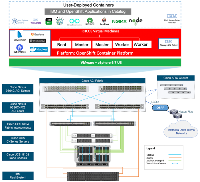
VersaStack Physical Topology
The VersaStack infrastructure satisfies the high-availability design requirements and is physically redundant across the network, compute and storage stacks. Figure 25 provides a high-level topology of the system connectivity.
This VersaStack design utilizes Cisco UCS platform with Cisco UCS B200 M5 half-width blades and Cisco UCS C220 M5 servers connected and managed through Cisco UCS 6454 Fabric Interconnects and the integrated Cisco UCS Manager (UCSM). These high-performance servers are configured as stateless compute nodes where ESXi 6.7 U3 hypervisor is loaded using SAN (iSCSI) boot. The boot disks to store ESXi hypervisor image and configuration along with the block based datastores to host application Virtual Machines (VMs) are provisioned on the IBM Flash System family storage array.
Similar to the non-ACI designs of VersaStack, link aggregation technologies play an important role in VersaStack with ACI solution providing improved aggregate bandwidth and link resiliency across the solution stack. Cisco UCS, and Cisco Nexus 9000 platforms support active port channeling using 802.3ad standard Link Aggregation Control Protocol (LACP). In addition, the Cisco Nexus 9000 series features virtual Port Channel (vPC) capability which allows links that are physically connected to two different Cisco Nexus devices to appear as a single "logical" port channel.
This design has the following physical connectivity between the components of VersaStack:
· 4 X 25 Gb Ethernet connections port-channeled between the Cisco UCS 5108 Blade Chassis and the Cisco UCS Fabric Interconnects
· 25 Gb Ethernet connections between the Cisco UCS C-Series rackmounts and the Cisco UCS Fabric Interconnects
· 100 Gb Ethernet connections port-channeled between the Cisco UCS Fabric Interconnect and Cisco Nexus 9000 ACI leaf’s
· 100 Gb Ethernet connections between the Cisco Nexus 9000 ACI Spine’s and Nexus 9000 ACI Leaf’s
· 25 Gb Ethernet connections between the Cisco Nexus 9000 ACI Leaf’s and IBM Flash System storage array for iSCSI block storage access
Figure 25 VersaStack Physical Topology
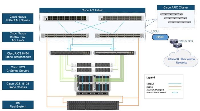
VersaStack with OCP Logical Topology
Figure 26 illustrates the VersaStack UPI with Red Hat OpenShift Container Platform logical topology with OCP components utilizing compute, network, and storage resources on VersaStack. The storage and network connectivity to Red Hat OpenShift Container Platform Cluster nodes running on VMware vSphere high availability cluster (deployed on the Cisco UCS B200 M5 servers) is enabled by the Cisco Nexus 9k switches within VersaStack. The Red Hat OpenShift Container Platform environment has been deployed on VersaStack without any major modifications made to the infrastructure.
Persistent storage is a critical part of running stateful containers, and Red Hat OpenShift Container Platform with Kubernetes simplifies storage management by abstracting details of how storage is provisioned and how it is consumed. Persistent volumes for containers can be static or dynamically provisioned, in this case it is dynamic with VersaStack and is enabled by IBM CSI Driver for Block Storage. Dynamic volume provisioning allows storage volumes to be created on-demand, IBM CSI for Containers eliminates the need to pre-provision storage for containers and allows persistent storage provisioning during the container deployment.
The storage resources can be dynamically provisioned using the IBM CSI driver specified by the StorageClass object. Storage Classes are essentially blueprinting that abstract away the underlying storage provider, as well as other parameters, like disk-type, for example SSD vs HDD if a hybrid storage array is used. This solution used iSCSI storage for dynamic storage provisioning with optional support for FC block storage.
Figure 26 VersaStack UPI for OCP – End-to-End Logical Overview
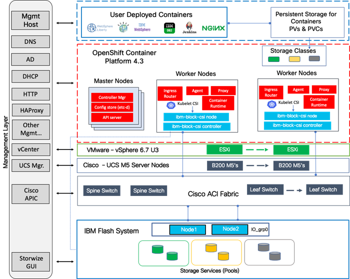
VersaStack Network Connectivity and Design
In this VersaStack design, a pair of redundant Cisco Nexus 9336C-FX2 leaf switches provide ACI based Ethernet switching fabric for iSCSI storage access for the compute and application communication. A second pair of Nexus 9000 leaf switch provides connectivity to existing enterprise (non-ACI) networks. The core network constructs such as virtual port channels (vPC) and VLANs plays an important role in providing the necessary Ethernet based IP connectivity.
Virtual Port Channel Design
In the VersaStack with Cisco ACI and IBM FlashSystem design leveraged for this solution, Cisco UCS FIs are connected to the ACI fabric using a vPC. Network reliability is achieved through the configuration of virtual Port Channels within the design as shown in Figure 27.
Figure 27 Network Connectivity – vPC Enabled Connections
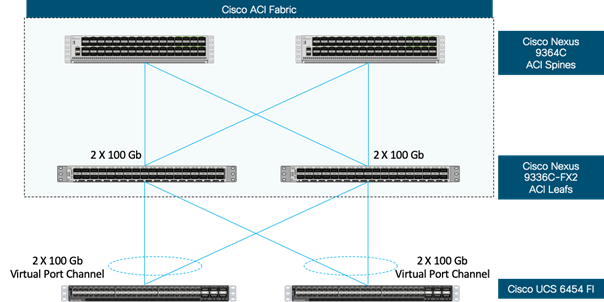
Virtual Port Channel allows Ethernet links that are physically connected to two different Cisco Nexus 9336C-FX2 ACI Leaf switches to appear as a single Port Channel. vPC provides a loop-free topology and enables fast convergence if either one of the physical links or a device fails. In this design, two 100G ports from the 40/100G capable ports on the 6454 (1/49-54) were used for the virtual port channels.
Application Centric Infrastructure Design
The Cisco ACI design consists of Cisco Nexus 9500 and 9300 based spine/leaf switching architecture controlled using a cluster of three Application Policy Infrastructure Controllers (APICs). With the Nexus switches in place, the platform delivers an intelligently designed, high port density, low latency network, supporting up to 400G connectivity.
In the VersaStack with ACI design, Cisco UCS FI, IBM FlashSystem and Cisco Nexus 7000 based WAN/Enterprise routers are connected to leaf switches, each of these devices are redundantly connected to a pair of leaf switches for high availability.
Figure 28 shows the VersaStack ACI fabric with connectivity to Cisco UCS Compute, IBM FlashSystem storage, APIC Cluster for management and existing enterprise networks via Cisco Nexus 7000s.
Figure 28 VersaStack Data Center – ACI Fabric Sub-system Connectivity (High-Level)
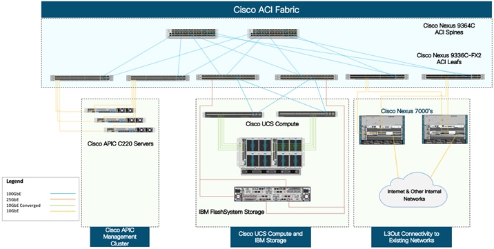
The access layer connections on the ACI leaf switches to the different sub-systems in this design are summarized below:
· Cisco APICs that manage the ACI Fabric (3-node cluster)
- Cisco APIC that manages the ACI fabric is redundantly connected to a pair of ACI leaf switches using 2x10GbE links. For high availability, an APIC cluster with 3 APICs are used in this design. The APIC cluster connects to an existing pair of ACI leaf switches in the ACI fabric.
· Cisco UCS Compute Domain (Pair of Cisco UCS Fabric Interconnects) with Cisco UCS Servers
- A Cisco UCS Compute domain consisting of a pair of Cisco UCS 6400 Fabric Interconnects, connect into a pair of Nexus 9336C-FX2 leaf switches using port-channels, one from each FI. Each FI connects to the leaf switch-pair using member links from one port-channel.
· IBM FlashSystem Storage Array
- An IBM FlashSystem control enclosure with two node canisters connect into a pair of Nexus 9336C-FX2 leaf switches using access ports, one from each node canister.
· Cisco Nexus 7000 series switches (Gateways for L3Out)
IBM FlashSystem– iSCSI Connectivity
To support iSCSI-based IP storage connectivity with redundancy, each IBM FlashSystem node canister is connected to each of the Cisco Nexus 9336C-FX2 leaf switches for iSCSI boot and VMware datastore access. The physical connectivity is shown in Figure 29. Two 25GbE ports from each IBM FlashSystem are connected to each of the two Cisco Nexus 9336C-FX2 switches providing an aggregate bandwidth of 100Gbps for storage access. The 25Gbps Ethernet ports between the FlashSystem I/O Group and the Cisco Nexus fabric are utilized by redundant iSCSI-A and iSCSI-B paths, providing redundancy for link and device failures. Additional links can be added between the storage and network components for additional bandwidth if needed.
The Cisco Nexus 9336C-FX2 switches used in the design support 10/25/40/100 Gbps on all the ports. The switch supports breakout interfaces, where each 100Gbps port on the switch can be split in to 4 X 25Gbps interfaces. In this design, a breakout cable is used to connect the 25Gbps iSCSI ethernet ports on FlashSystem storage array to the 100Gbps QSFP port on the switch end. With this connectivity, IBM SFP transceivers on the FlashSystem are not required.
![]() Connectivity between the Cisco Nexus switches and IBM FlashSystem for iSCSI access depends on the Nexus 9000 switch model used within the architecture. If other supported models of the Cisco Nexus switches with 25Gbps capable SFP ports are used, breakout cable is not required and ports from the switch to IBM FlashSystem can be connected directly using the SFP transceivers on both sides.
Connectivity between the Cisco Nexus switches and IBM FlashSystem for iSCSI access depends on the Nexus 9000 switch model used within the architecture. If other supported models of the Cisco Nexus switches with 25Gbps capable SFP ports are used, breakout cable is not required and ports from the switch to IBM FlashSystem can be connected directly using the SFP transceivers on both sides.
Figure 29 IBM FlashSystem - iSCSI Connectivity with Cisco Nexus 9336C-FX2 ACI Leaf Switch
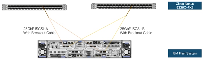
VersaStack Compute Connectivity
The VersaStack compute design supports both Cisco UCS B-Series and C-Series deployments. Cisco UCS supports the virtual server environment by providing robust, highly available, and integrated compute resources centrally managed from Cisco UCS Manager in the Enterprise or from Cisco Intersight Software as a Service (SaaS) in the cloud. In this validation effort, multiple Cisco UCS B-Series and C-Series ESXi servers are booted from SAN using iSCSI storage presented from the IBM Flash System.
Figure 30 Compute Connectivity
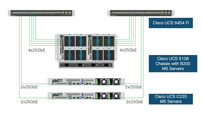
The Cisco UCS 5108 chassis in the design is populated with Cisco UCS B200 M5 blade servers and each of these blade servers contain one physical network adapter (Cisco VIC 1440) that passes converged fibre channel and ethernet traffic through the chassis mid-plane to the 2408 FEXs. The FEXs are redundantly connected to the fabric interconnects using 4X25Gbps ports per FEX to deliver an aggregate bandwidth of 200Gbps to the chassis. Full population of each 2408 FEX can support 8x25Gbps ports, providing an aggregate bandwidth of 400Gbps to the chassis.
The connections from the Cisco UCS Fabric Interconnects to the FEXs are automatically configured as port channels by specifying a Chassis/FEX Discovery Policy within UCSM.
Cisco UCS Server Configuration for VMware vSphere
The Cisco UCS servers are stateless and are deployed using Cisco UCS Service Profiles (SP) that consists of server identity information pulled from pools (WWPN, MAC, UUID, and so on) as well as policies covering connectivity, firmware and power control options, and so on. The service profiles are provisioned from the Cisco UCS Service Profile Templates that allow rapid creation, as well as guaranteed consistency of the hosts at the Cisco UCS hardware layer.
The ESXi nodes consist of Cisco UCS B200 M5 blades or Cisco UCS C220 M5 rack servers with Cisco UCS 1400 series VIC. These nodes are allocated to a VMware High Availability cluster to support infrastructure services and applications. At the server level, the Cisco 1400 VIC presents multiple virtual PCIe devices to the ESXi node and the vSphere environment identifies these interfaces as vmnics or vmhbas. The ESXi operating system is unaware of the fact that the NICs or HBAs are virtual adapters.
In the VersaStack design with iSCSI storage, six vNICs are created and utilized as follows (Figure 31):
· One vNIC (iSCSI-A) for iSCSI SAN traffic
· One vNIC (iSCSI-B) for iSCSI SAN traffic
· Two vNICs for in-band management and vMotion traffic
· Two vNICs for application virtual machines hosted on the infrastructure. These vNICs are assigned to a distributed switch (vDS) managed by Cisco ACI
Figure 31 Cisco UCS – Server Interface Design for iSCSI-based Storage Access
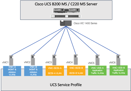
Virtual Switching Architecture
A tenant application (OpenShift Container Platform) deployment utilizes port groups on APIC controlled distributed switch (VDS). However, for some of the core connectivity such as out-of-band management access, vSphere vMotion and storage LUN access using iSCSI vSphere vSwitches are deployed. To support this multi-vSwitch requirement, multiple vNIC interfaces are setup in Cisco UCS services profile and storage, management and data VLANs are then enabled on the appropriate vNIC interfaces.
Figure 32 shows the distribution of VMkernel ports and VM port-groups on VMware ESXi server. For an ESXi server, supporting iSCSI-based storage access, In-band management and vMotion traffic is handled by a Foundation Services vSwitch and iSCSI-A and iSCSI-B traffic is handled by a dedicated iSCSI vSwitch. The VMkernel configuration of both management and vMotion are pinned in an active/standby configuration setting on opposing links, to keep these types of traffic contained within a particular Cisco UCS fabric interconnect when switching this traffic between ESXi hosts, thus preventing the need to send it up into the Nexus switch to pass between fabrics. The resulting ESXi host configuration therefore has a combination of 2 vSwitches and a single APIC-Controlled distributed switch which handles application (tenant) specific traffic.
Figure 32 Virtual Networking Diagram for a Cisco UCS B200 M5 ESXi Host
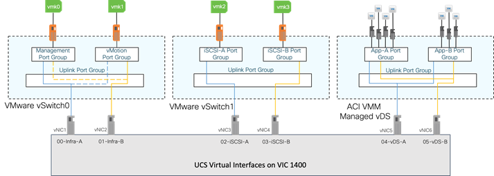
Red Hat OpenShift Container Platform Architecture
For the purpose of this CVD, the team deployed a highly available and scalable OpenShift Container Platform cluster. The nodes are deployed as VMs on supported RHCOS guest OS. Figure 33 illustrates the architectural view of OpenShift Container Platform.
Figure 33 Red Hat OpenShift Container Platform – Architecture

OCP is deployed on the hypervisor as a set of VMs. Each VM is a node with a role to carry specific functions within the OCP cluster.
The control plane, which is composed of master machines, manages the OpenShift Container Platform cluster. The control plane machines manage workloads on the compute machines, which are also known as worker machines. The cluster itself manages all upgrades to the machines by the actions of the Cluster Version Operator, the Machine Config Operator, and set of individual Operators.
Cluster Workers
In a Kubernetes cluster, the worker nodes are where the actual workloads requested by Kubernetes users run and are managed. The worker nodes advertise their capacity and the scheduler, which is part of the master services, determines on which nodes to start containers and Pods. Important services run on each worker node, including CRI-O, which is the container engine, Kubelet, which is the service that accepts and fulfills requests for running and stopping container workloads, and a service proxy, which manages communication for pods across workers.
There are four worker nodes in our initial test environment, additional worker nodes were added during the testing procedures to verify the scalability of the solution.
Cluster Masters
In a Kubernetes cluster, the master nodes run services that are required to control the Kubernetes cluster. In OpenShift Container Platform, the master machines are the control plane. They contain more than just the Kubernetes services for managing the OpenShift Container Platform cluster.
Multiple master nodes are required in a high availability environment to allow for failover if the leading master host fails. There are three Master nodes in our test environment to provide high availability cluster, each is deployed on a separate host (ESXi) for redundancy.
Operators in OpenShift Container Platform
In OpenShift Container Platform, Operators are the preferred method of packaging, deploying, and managing services on the control plane. They also provide advantages to applications that users run. Operators integrate with Kubernetes APIs and CLI tools such as kubectl and oc commands. They provide the means of watching over an application, performing health checks, managing over-the-air updates, and ensuring that the applications remain in your specified state.
We have leveraged the available operators for IBM CSI and some other sample applications during the validation of this solution. The deployment details are explained in the following sections of this document
OpenShift Ingress and Egress Traffic flow
There are two main components of OpenShift Networking, the OpenShift Software Defined Network plug-in to handle the communication within the cluster and the OpenShift Router plug-in to handle the inbound and outbound traffic destined to Services in the cluster.
The default OpenShift SDN solution is built on top of Open vSwitch (OVS). With OpenShift, the cluster admin can choose to deploy with one of the OpenShift native SDN plug-in or they can opt to deploy the cluster using a third-party SDN from the supported ecosystem such as Cisco ACI. For this solution, we have used the OpenShift native SDN plug-in.
OpenShift internal cluster communication with OpenShift SDN
OpenShift container Platform uses a software defined networking approach to provide unified cluster network that assigns an internal IP address to each Pod in the cluster to ensure all containers within the Pod behave as though they were on the same host. In terms of port allocation, networking, naming, load balancing and application configuration, is the same as though they were physical hosts or virtual machines.
![]() A pod is one or more containers deployed together on one host, and the smallest compute unit that can be defined, deployed, and managed. Pods are the rough equivalent of a machine instance (physical or virtual) to a container. Each pod is allocated its own internal IP address, therefore owning its entire port space, and containers within pods can share their local storage and networking.
A pod is one or more containers deployed together on one host, and the smallest compute unit that can be defined, deployed, and managed. Pods are the rough equivalent of a machine instance (physical or virtual) to a container. Each pod is allocated its own internal IP address, therefore owning its entire port space, and containers within pods can share their local storage and networking.
This Pod network is established and maintained by the OpenShift SDN, which configures an overlay network using Open vSwitch (OVS).
OpenShift SDN provides three SDN plug-ins for configuring the pod network:
· The ovs-subnet plug-in is the original plug-in, which provides a "flat" pod network where every pod can communicate with every other pod and service.
· The ovs-multitenant plug-in provides project-level isolation for pods and services. Each project receives a unique Virtual Network ID (VNID) that identifies traffic from pods assigned to the project. Pods from different projects cannot send packets to or receive packets from pods and services of a different project.
· The ovs-networkpolicy plug-in allows project administrators to configure their own isolation policies using NetworkPolicy objects.
OpenShift SDN maintains a registry of all nodes in the cluster, this registry is stored in etcd. When the system administrator registers a node, OpenShift SDN allocates an unused /23 subnet from the cluster network and stores this subnet in the registry. When removing or deleting a node from the cluster, the OpenShift SDN frees the corresponding cluster network subnet. This subnet becomes available for future allocations to new nodes.
In the default configuration, the cluster network is the 10.128.0.0/14 network (such as 10.128.0.0 - 10.131.255.255), and nodes are allocated /23 subnets (such as 10.128.0.0/23, 10.128.2.0/23, 10.128.4.0/23, and so on). This means that the cluster network has 512 subnets available to assign to nodes, and a given node is allocated 510 addresses that it can assign to the containers running on it. The size and address range of the cluster network are configurable, as is the host subnet size.
To identify the cluster network subnet allocated to each node, execute the “oc get hostsubnet” command with user having cluster-admin privilege as shown below:
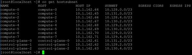
When a Node is added to the cluster, the OpenShift SDN registers the local host with the registry on Master to allocate an open subnet to the node.
OpenShift SDN creates and configures three network devices:
· br0: Open Virtual Switch (OVS) bridge device that Pod containers will be attached to. OpenShift SDN also configures a set of non-subnet-specific flow rules on this bridge.
· tun0: Open Virtual Switch (OVS) internal port (port 2 on br0). This gets assigned the cluster subnet gateway address and is used for external network access. OpenShift SDN configures netfilter and routing rules to enable access from the cluster subnet to the external network by way of NAT.
· vxlan_sys_4789: The OVS VXLAN device (port 1 on br0), which provides access to containers on remote nodes. Referred to as vxlan0 in the OVS rules.
Each time a pod is started on the host, OpenShift SDN:
· Assigns the pod a free IP address from the node’s cluster subnet.
· Attaches the host side of the pod’s veth interface pair to the OVS bridge br0.
· Adds OpenFlow rules to the OVS database to route traffic addressed to the new pod to the correct OVS port.
Figure 34 Pod to Pod communication
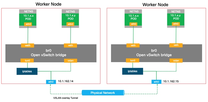
If both containers are running in the same node, then the communication flow from one Pod to another using the vethX interface from the same br0 interface of the node.
If the containers are running on different nodes, then the flow of packets from one Pod to another use the vethX interface from the br0 ovs interface on different nodes
Finally, if the Pod connects to an external host, the traffic flow from the eth0 interface in the Pod to the vethX in the Linux bridge, then to br0 interface in the ovs and use the tun0 interface through the eth0 to the physical network.
OpenShift External Cluster Communication
OpenShift Container Platform provides the following methods for communicating from outside the cluster with services running in the cluster.
Administrators can expose a service endpoint that external traffic can reach, by assigning a unique external IP address to that service from a range of external IP addresses, this IP address range is specified using a CIDR notation, which allows an application user to make a request against the cluster for an external IP address.
Each IP address must be assigned to only one service to ensure that each service has a unique endpoint.
The following methods are recommended, in order of preference:
· If you have HTTP/HTTPS, use an Ingress Controller.
· Otherwise, use a Load Balancer, an External IP, or a NodePort.
Using Ingress Controllers and Routes
The Ingress Operator manages Ingress Controllers and wildcard DNS. Using an Ingress Controller is the most common way to allow external access to an OpenShift Container Platform cluster.
An Ingress Controller is configured to accept external requests and proxy them based on the configured routes. This is limited to HTTP, HTTPS using SNI, and TLS using SNI, which is sufficient for web applications and services that work over TLS with SNI.
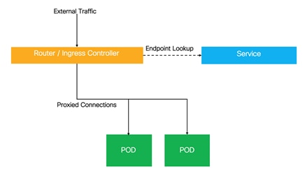
Using Load Balancer
This method allows traffic to nonstandard ports through an IP address assigned from a pool.
If you do not need a specific external IP address, you can configure a load balancer service to allow external access to an OpenShift Container Platform cluster.
A load balancer service allocates a unique IP. The load balancer has a single edge router IP, which can be a virtual IP (VIP), but is still a single machine for initial load balancing.
Using a NodePort
NodePort is used to expose the service on a static port on all nodes in the cluster as shown in below.
NodePorts are in the 30000-32767 range by default, which is unlikely to match a service’s intended port.
For service and application access the administrator must ensure the external IPs are routed to the nodes and local firewall rules on all nodes allow access to the open port. The DNS wildcard feature can be used to configure resolution for a subset of names to an IP address in the cluster.
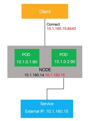
Using a Service External IP
One method to expose a service is to assign an external IP address directly to the service you want to make accessible from outside the cluster.
The external IP address that you use must be provisioned on your infrastructure platform and attached to a cluster node.
With an external IP on the service, OpenShift Container Platform sets up sets up NAT rules to allow traffic arriving at any cluster node attached to that IP address to be sent to one of the internal pods. This is similar to the internal service IP addresses, but the external IP tells OpenShift Container Platform that this service should also be exposed externally at the given IP. The administrator must assign the IP address to a host (node) interface on one of the nodes in the cluster. Alternatively, the address can be used as a virtual IP (VIP).
These IPs are not managed by OpenShift Container Platform and administrators are responsible for ensuring that traffic arrives at a node with this IP.
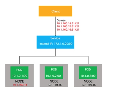
Red Hat OpenShift Container Platform Deployment on VersaStack
For the validated design effort, the team focused on building and testing a basic OCP environment. Four UCS servers for four ESXi servers were installed and configured within vCenter to host the OCP nodes, all were RHCOS as the guest OS VMs.
Table 1 lists the number of nodes and the associated specifications that were deployed in this solution.
![]() The number of nodes and roles adhere to Red Hat’s architecture as described in the OpenShift documentation: https://docs.openshift.com/container-platform/4.3/welcome/index.html
The number of nodes and roles adhere to Red Hat’s architecture as described in the OpenShift documentation: https://docs.openshift.com/container-platform/4.3/welcome/index.html
Table 1 OCP Nodes and Specifications
| Machine |
Number of Nodes |
vCPU |
RAM |
Storage |
Comment |
| Bootstrap |
1 |
4 |
16 GB |
120GB |
Bootstrap node |
| Control plane |
3 |
4 |
16 GB |
120GB |
Control plane/Master nodes |
| Compute |
4* |
4 |
16 GB |
120GB |
Compute/Worker nodes |
*4 additional worker nodes were added to validate scalability
All nodes were configured as RHCOS VMs, running on the ESXi servers as depicted in Figure 35.
Figure 35 OpenShift Container Platform Nodes
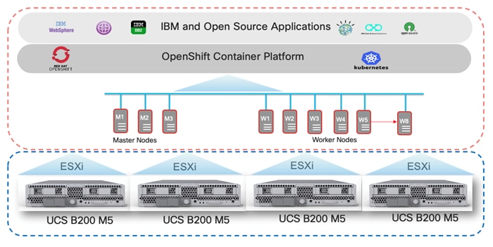
OpenShift Cluster Node connectivity on VersaStack
The compute resources in this architecture are grouped into a VMware ESXi infrastructure cluster. Servers in the cluster host the virtual machines used for OCP infrastructure deployment. High availability features available in VMware vSphere are leveraged to provide virtualization layer resiliency.
Red Hat OpenShift Container Platform deployment utilizes one dedicated port group on the application VMware distributed switch (VDS) within the VMware ESXi servers on VersaStack. This is the physical underlay network for OpenShift SDN for communication between the PODs across the cluster nodes. The OCP management nodes have one virtual NIC connected to OCP port group for communication between the OCP nodes. The Worker nodes have three virtual NICs, one NIC connected to OCP port group for communication between the OCP nodes, the other two NIC’s connected to the iSCSI port groups to enable iSCSI storage access to the IBM FlashSystem. The OCP worker nodes need iSCSI storage access for dynamic storage provisioning.
Figure 36 VMware ESXi Host and OCP Nodes Connectivity
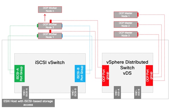
VersaStack Storage Design for OCP
The VersaStack for OCP is based on IBM FlashSystem storage system with Spectrum Virtualize version 8.3.1. IBM CSI driver for block storage is an add-on component that needs to be installed on the OpenShift Container Platform cluster. IBM CSI enables the integration between the storage and OCP cluster.
The block storage on the IBM FlashSystem storage arrays support both fibre channel and iSCSI protocols. For the purpose of this validated design, iSCSI was used for the ESXi servers’ boot and also for the underlying datastores and for additional applications that may be hosted on the VersaStack stack.
Dynamic Storage Provisioning
Dynamic provisioning is a feature that is native to Kubernetes and that allows a cluster developer to order storage with a pre-defined type and configuration without knowing all the details about how to provision the physical storage device. To abstract the details for the specific storage type, the cluster admin must create storage classes that the developer can use.
OpenShift adds to Kubernetes a number of VolumeProviders, which provide access to enterprise storage, such as iSCSI, Fibre Channel, Gluster, or a cloud block volume service such as OpenStack Cinder.
OpenShift also provides dynamic provisioning of storage for applications by way of the StorageClass resource. Using dynamic storage, you can select different types of back-end storage. The back-end storage is segregated into different tiers depending on the needs of your application. For example, a cluster administrator can define a StorageClass with the name of “fast,” which makes use of higher quality back-end storage, and another StorageClass called “slow,” which provides commodity-grade storage. When requesting storage, a user can specify a PersistentVolumeClaim with an annotation that specifies the value of the StorageClass they prefer.
To order the storage, you must create a PVC. The PVC determines the specification for the storage that you want to provision. After the PVC is created, the storage device and the PV are automatically created for you.
Figure 37 shows how block storage is dynamically provisioned in a cluster. This sample flow works similarly with other storage types, such as file storage.
Figure 37 Dynamic Storage provisioning Workflow
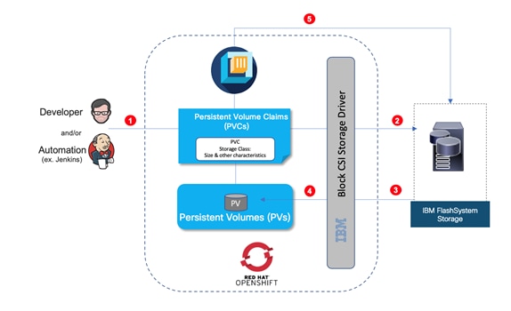
· Developer/Automation submits storage requirements in the form of standard Persistent Volume Claims that specifies the storage type, storage class, size, and so on.
· CSI Plugin listens to and intercepts Persistent Volume Claims based on Storage Class. Creating a PVC in a cluster automatically triggers the storage plug-in for the requested type of storage to provision storage with the given specification.
· Storage provisioning API call sent to IBM FlashSystem and storage is provisioned.
· The storage plug-in automatically creates a persistent volume (PV) in the cluster, a virtual storage device that points to the actual storage device on your VersaStack IBM FlashSystem.
· The PVC and PV are automatically connected to each other. The status of the PVC and the PV changes to Bound and the PVC is used to mount persistent storage to your app. If you delete the PVC, the PV and related storage instance are also deleted.
Considerations
The following sections outline the design considerations for the VersaStack with Red Hat OpenShift Container Platform solution.
Resiliency
The VersaStack for OCP solution addresses infrastructure resiliency by including redundancy in its design and implementation at the level of each component (compute, network and storage). Design considerations and best practices associated with fault tolerance, resiliency and other redundancy aspects to help ensure high availability of the converged infrastructure are addressed in a previously published CVDs which can be found from the following links:
https://www.cisco.com/c/en/us/td/docs/unified_computing/ucs/UCS_CVDs/versastack_ibm_9100nvme.html
Additional crucial element of resiliency is provided at the hypervisor level (VMware vSphere) managed by vCenter. In our specific reference there are four physical servers for the four ESXi hosts. Three are required in order to support three master nodes, which is the required number of nodes for highly available OCP platform. The fourth host is then used for high availability and is redundant until a failure. The fourth server also will be used to host additional Worker nodes. It is important to size the entire set of compute, network and storage to accommodate the expected workloads not only from the perspective of the OCP nodes but also to account for user applications.
Mapping the OCP nodes to an ESXi server is not important and infrastructure teams can rely on the hypervisor layer to automatically manage the VMs affectively across the available pool of resources.
It is critical however to prevent a situation in which the Master nodes, that have critical role in the availability of the service, from being hosted on the same underlying ESXi server. Only one Master node should be allowed on each of the ESXi servers. Since there are three Master nodes in our cluster, we will need a fourth ESXi server as a standby to host nodes from a failed ESXi. Given the number of total nodes and expected total workloads, our recommendation is to have the fourth ESXi server in order to have the proper redundancy. That makes the topology of physical ESXi servers as N + 1. In larger environments with more nodes the topology may call for N + 2 or more.
Infrastructure teams can configure rules in the VMware environment to manage this level of resiliency. In our CVD testing the team configured VMware DRS Anti-Affinity rules to make sure that no more than one Master node will be hosted per ESXi server.
The team also tested an ESXi failure and observed the expected behavior of the impacted running nodes failing over to other available resources in the pool, including the fourth ESXi hosting the Master server from the failed ESXi.
VMware vMotion provides the functionality of moving VMs automatically across the available pool of resources and according to set of rules if defined by the administrator. vMotion networks were also defined on the ESXi host to handle the associated network traffic.
Scalability
VersaStack is highly scalable and flexible converged infrastructure stack from which OCP customers can benefit. Various components with in VersaStack can scale easily and can be managed with the same element management system. Cisco UCS servers can be easily added, additional network ports and modules can be added and also storage capacity and additional controllers can be added, all in a non-disruptive fashion, allowing organization to scale easily as they add data and services to the platform. Without impacting the availability of the service.
In some cases, scalability will have multiple dimensions, so not just vertically by adding more memory or capacity to the storage system but also horizontally by adding more units of compute, network ports and storage controllers. New UCS units may include higher core count and more memory than previously deployed servers, which will support higher total of workload.
This flexibility in how the VersaStack platform can scale helps organization optimize the balance between performance and cost and allow them to allocate the right amount of resources to the required task and change that easily if and when needed.
Sizing and Performance
This is a general recommendation and not specific to a customer environment. It is important to properly size the solution with all of its components by a qualified Engineer / Architect per the specific requirements of the customer. There is no one size fits all approach, hence specific sizing and performance testing were excluded from the CVD. However, Cisco, Red Hat, IBM, and their partners, do all provide tools and/or resources to help organizations optimize the sizing of the solution to meet the required performance in the most economical way.
For example, at the Cisco UCS level, customers have the option to include servers with different processors and core counts, and with the combination of the right amount of memory the servers can be optimized for the right cost-performance configuration. The same strategy is applicable across all the layers of VersaStack including network and storage.
It is important to size the servers to meet the minimal requirements of the OCP platform, to account for failures of servers and by that to make sure that VMware DRS related rules can be followed upon server failure with enough resources available for VMware to redistribute the VMs from the failing host or when performing upgrades and other maintenance tasks.
Example Sizing Guidelines (Worker Nodes)
Determine how many nodes and pods are required for your OpenShift Container Platform cluster. Cluster scalability correlates to the number of pods in a cluster environment. That number influences the other numbers in your setup. See Cluster Limits for the latest limits for objects in OpenShift Container Platform.
Environment sizing can be done according to tested cluster maximums or according to your application requirements. While planning your environment, determine how many pods are expected to fit per node:
Required Pods per Cluster / Pods per Node = Total Number of Nodes Needed
If you want to scope your cluster at 2500 pods, assuming the 250 maximum pods per node, you would need at least ten nodes:
2500 / 250 = 10
If you increase the number of nodes to 15, the pods per node distribution changes to 167 pods per node.
The current maximum number of pods per node is 250. However, the number of pods that fit on a node is dependent on the application itself. Consider the application’s memory, CPU, and storage requirements.
Consider a sample application environment having the following components:
| Pod type |
Pod quantity |
Max memory |
CPU cores |
Persistent storage |
| apache |
100 |
500 MB |
0.5 |
1 GB |
| node.js |
200 |
1 GB |
1 |
1 GB |
| postgresql |
100 |
1 GB |
2 |
10 GB |
The overall resource requirements for this application are: 450 CPU cores, 350GB RAM, and 1.3TB storage
Some applications lend themselves well to overcommitted environments, and some do not. Most Java applications and applications that use huge pages are examples of applications that would not allow for overcommitment. That memory cannot be used for other applications. The sizing can be based on the assumption that applications need dedicated resources or can tolerate overcommitment. The following are some sample scenarios:
· Scenario 1: Dedicated resources
· Scenario 2: 30 percent overcommitted resources
· Scenario 3: 50 percent overcommitted resources (Nonproduction environment)
Since you are using VMware virtualization on VersaStack and not dedicated bare metal servers as OCP nodes, you need to account for virtualization overhead. VMware suggests using the following formula while sizing the OpenShift environment worker nodes.
![]() As per VMware, “the factor of 0.85 is a practical approximation for the reserved capacity for ample vSphere headroom of 15%, tested for mission-critical applications with deterministic performance such as trading systems”.
As per VMware, “the factor of 0.85 is a practical approximation for the reserved capacity for ample vSphere headroom of 15%, tested for mission-critical applications with deterministic performance such as trading systems”.
| Memory Size |
(0.85 * Total RAM on Host) / Number of Sockets |
| vCPU (*) |
(0.85 * Total Logical Processors on Host) / Number of Sockets)
|
(*) Hyperthreaded vCPUs
![]() For the maximum size of worker nodes, take into consideration the CPU architecture – such as Non-Uniform Memory Architecture (NUMA) and Hyperthreading on the UCS servers.
For the maximum size of worker nodes, take into consideration the CPU architecture – such as Non-Uniform Memory Architecture (NUMA) and Hyperthreading on the UCS servers.
For example, a sample application with a formula calculated the size of worker nodes based on vSphere cluster to support a single OCP cluster with dedicated resources (Scenario 1) on a Cisco UCS server is as follows:
With a reference Cisco UCS server with following specifications:
· Intel Dual-Socket with 28 physical CPU’s per socket (56 logical CPUs with hyper-threading) and 256GB (8 X 32GB DIMMs) RAM.
The available resources with the calculation per Cisco UCS server would be:
· CPUs = (112 X 0.85) / 2 = 48 vCPUs
· Memory = (512 GB X 0.85) / 2 = 218 GB RAM
The number of Worker nodes required for the above same application can be calculated as below:
· 450 CPU cores = 450 / 48 = 9 UCS servers
· 350GB RAM = 350 / 218 = 2 UCS servers
· 1.3TB storage = 1.3 TB capacity available on IBM FlashSystem Pool
If you use the lowest common denominator (CPUs required) needed to support the resource requirement, the minimum number of worker nodes will be 9, assuming we deploy one worker node per Cisco UCS server and can go up to 225 worker nodes if each worker node is deployed with minimum resources required (2 vCPUs).
Architecture
This section provides the details about the deployment of OpenShift Container Platform 4.3 on the VersaStack Converged Infrastructure as tested and validated in our lab. It focuses on configurations and settings that are specific to OCP and it does not cover generic details on how to set up the hardware components of the VersaStack or vSphere, which were explained in a previously published CVDs and other technical publications from Cisco and IBM.
For detailed instructions to set up the VersaStack infrastructure, refer to the following CVDs:
https://www.cisco.com/c/en/us/td/docs/unified_computing/ucs/UCS_CVDs/versastack_ibm_9100nvme.html
Figure 38 illustrates the logical topology of the OpenShift container platform along with the required infrastructure services required as deployed in the validation lab.
Figure 38 Validated - OpenShift Container Platform Logical Topology
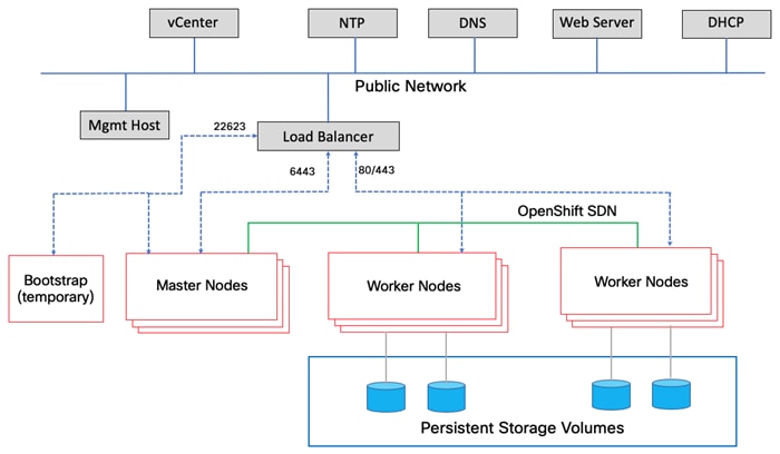
Deployment Hardware and Software
The deployment of hardware and software for VersaStack with OpenShift Container Platform is detailed in the following sections.
The existing deployment of the VersaStack architecture is assumed, and the setup of these resources will have dependencies covered in the VersaStack with Cisco ACI and IBM FlashSystem NVMe-accelerated Storage deployment guide available here:
https://www.cisco.com/c/en/us/td/docs/unified_computing/ucs/UCS_CVDs/versastack_ibm_9100nvme.html
Deployment Hardware
Table 2 lists the hardware and software versions used during solution validation. It is important to note that Cisco, IBM, and VMware have interoperability matrixes that should be referenced to determine support for any specific implementation of VersaStack. Click the following links for more information:
· IBM System Storage Interoperation Center
· Cisco UCS Hardware and Software Interoperability Tool
Table 2 Hardware and Software Revisions
| Layer |
Device |
Image |
Comments |
| Compute |
Cisco UCS Fabric Interconnects 6400 Series, Cisco UCS B200 M5 & Cisco UCS C220 M5 |
4.1 (1a) |
Includes the Cisco UCS-IOM 2408, Cisco UCS Manager, Cisco UCS VIC 1440 and Cisco UCS VIC 1457 |
| Cisco nenic Driver |
1.0.31.0 |
Ethernet driver for Cisco VIC |
|
| Cisco nfnic Driver |
4.0.0.48 |
FCoE driver for Cisco VIC |
|
| Network |
Cisco APIC |
4.2(4i) |
ACI Controller |
| Cisco Nexus Switches |
N9000-14.2(4i) |
ACI Leaf Switches |
|
|
|
Cisco ExternalSwitch |
1.1 |
Cisco UCS Integration with ACI |
| Storage |
IBM FlashSystem |
8.3.1 |
Software version |
| Virtualization |
VMware vSphere ESXi |
6.7 update 3 |
Software version |
| VMware vCenter |
6.7 update 3 |
Software version |
|
| Cisco ACI Plugin |
4.2.1000.10 |
VMware ACI Integration |
|
| Software |
OpenShift Container Platform |
4.3 |
Software version |
| OCP Master Node |
RHCOS 4.3 |
OS version |
|
| OCP Worker Node |
RHCOS 4.3 |
OS version |
|
| Management Node |
RHEL 7.6 |
OS version |
|
| IBM CSI driver |
1.1.0 |
Software version |
Configuration Guidelines
This document provides the details to configure a fully redundant, highly available configuration for a VersaStack POD with OpenShift Container Platform environment. VersaStack infrastructure deployment is beyond the scope of this document and the following information is provided for reference. General reference is made to which component is being configured with each step, either 01 or 02 or A and B. For example, node01 and node02 are used to identify the two IBM storage controllers that are provisioned with this document, and Cisco Nexus A or Cisco Nexus B identifies the pair of Cisco Nexus switches that are configured. The Cisco UCS fabric interconnects are similarly configured.
The focus of this document is to provide details of steps required to provision multiple Cisco UCS hosts and OpenShift Container Platform nodes, and these examples are identified as: ESXi-Infra-iSCSI-Host-01, ESXi-Infra-iSCSI-Host-02 and control-plane-0, control-plane-0-1 and so on. to represent infrastructure hosts and OCP nodes deployed respectively in this document.
This document is intended to enable you to fully configure the customer environment. In this process, various steps require you to insert customer-specific naming conventions, IP addresses, and VLAN schemes, as well as to record appropriate MAC addresses. Table 3 lists the VLANs necessary for VersaStack deployment and is provided for reference. In this table, app VLANs are dynamically assigned VLANs from the APIC-Controlled VMware vSphere Distributed Switch.
Table 3 VersaStack Necessary VLANs
| VLAN Name |
VLAN |
Subnet |
Usage |
| Out-of-Band-Mgmt |
111 |
192.168.160.0/22 |
VLAN for out-of-band management interfaces |
| IB-MGMT |
11 |
172.20.100.0/22 |
Management VLAN to access and manage the servers |
| iSCSI-A |
3161 |
10.29.161.0/24 |
iSCSI-A path for booting both Cisco UCS B Series and Cisco UCS C Series servers and datastore access |
| iSCSI-B |
3162 |
10.29.162.0/24 |
iSCSI-B path for booting both Cisco UCS B Series and Cisco UCS C Series servers and datastore access |
| vMotion |
3173 |
10.29.173.0/24 |
VMware vMotion traffic |
| Native-VLAN |
2 |
N/A |
VLAN 2 used as Native VLAN instead of default VLAN (1) |
| App-vDS-VLANs |
1400-1499 |
10.1.160.0/22 |
VLANs for Application VM Interfaces residing in vDS based port groups (OCP environment also uses VLAN from this range) |
VersaStack Storage Configuration
The following storage elements were configured according to the Solution Design section of this document.
The initial setup and basic configurations of the storage system to meet the design are beyond the scope of this document and were covered in previously published CVD and other documents from IBM. This section does provide information about the specific storage elements that were deployed and configured to benefit this solution.
FlashSystem 7200 Storage System – Management Access
To configure and manage the various storage features and services, we used the IBM FlashSystem GUI. CLI is an alternative and fully supports all configuration and settings options.
1. The management GUI is accessible from a browser that points to the cluster management IP that was configured during the initial setup over https (https://192.168.162.14/ as used in lab).
2. When logged in, the dashboard screen is presented with the menu of options on the left side of the screen.
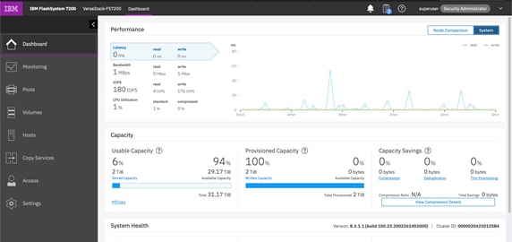
Storage Controllers and Storage Pool Configuration
This solution adheres to enterprise-grade requirements for redundancy and high availability. As described in the Technology Overview section, the IBM FlashSystem 7200 storage system has a high availability pair configuration which comprised of two storage controllers (2-nodes), and in the case of FlashSystem 7200 model, they are embedded within a single chassis. The nodes are both active and if one fails, the other controller (partner) will take over for continuous operation and availability of all storage services. The Storage nodes have redundant paths via two SAN fabrics to provide redundancy at switch and port level.
1. The nodes were configured as shown below in the system management UI.
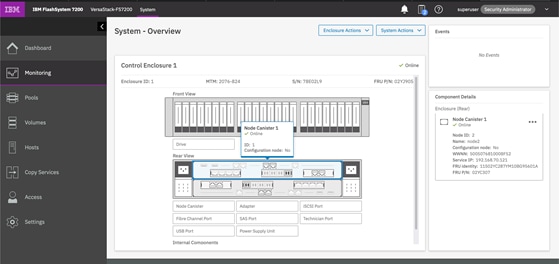
2. The list of the create Storage Pools is shown below.
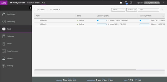
Network Configuration of the IBM FlashSystem
1. IBM FlashSystem – Storage nodes and IQN names details.
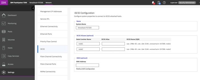
2. IBM FlashSystem – List of Network Interfaces for iSCSI access.
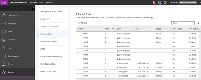
3. IBM FlashSystem – Storage Fabric VLANs for iSCSI access.

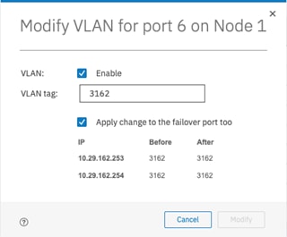
iSCSI LUNs
iSCSI LUNs were configured to support and enable SAN boot of the four ESXi servers and to present storage capacity for the data stores.
1. iSCSI boot LUNs for ESXi servers.
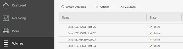
2. iSCSI datastore LUNs for ESXi servers.
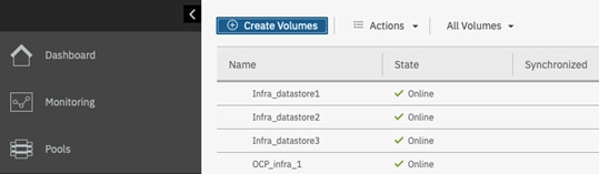
Configuring Host Clusters
When managing how volumes are mapped to Hosts, IBM Spectrum Virtualize incorporates the concept of Hosts and Host Clusters. In VersaStack configuration, each VMware ESXi (or physical server) instance is defined as an independent Host object within IBM FlashSystem. If each VMware ESXi host has multiple associated IQN ports, it is recommended that all ports associated with each physical host be contained within a single host object.
A Host Cluster was defined for each vSphere cluster. When mapping volumes from FlashSystem designed for VMFS Datastores, shared Host Cluster mappings have been used.
However, the SAN boot volumes are mapped to the specific host via private mappings. This will ensure that they remain accessible to only the corresponding VMware ESXi host.
To configure the host clusters, follow these steps:
1. Host Cluster and Volume Mapping.
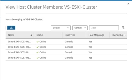
2. Volumes mapped to Host Cluster.
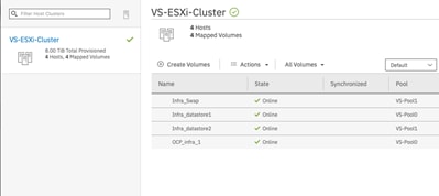
Data Protection (Optional)
1. Data protection can be enabled on the volumes by OCP environment, this helps customers recover their OCP environment if a disaster strikes or to protect against human errors. All IBM FlashSystem features and capabilities with local and remote replication can be leveraged for this purpose.
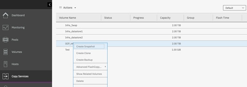
VersaStack Network Configuration
![]() The initial setup and network configurations for the VersaStack system are beyond the scope of this document.
The initial setup and network configurations for the VersaStack system are beyond the scope of this document.
Create an OCP Application Tenant with the Cisco ACI APIC
This section details the steps for creating OpenShift Container Platform application using Cisco APIC GUI. This tenant will comprise of one network tier which will be mapped to an EPG on the ACI fabric.
To deploy the Application Tenant and associate it to the VM networking, follow these steps:
Configure Tenant
1. In the APIC Advanced GUI, select Tenants.
2. At the top select Tenants > Add Tenant.
Name the Tenant VSV-OCP.
For the VRF Name, also enter VSV-OCP_VRF. Leave the Take me to this tenant when I click finish checkbox checked.
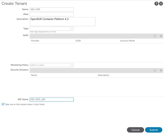
3. Click Submit to finish creating the Tenant.
Configure Bridge Domains
To configure bridge domains, follow these steps:
1. In the left pane expand Tenant VSV-OCP > Networking.
2. Right-click the Bridge Domain and select Create Bridge Domain.
![]() In this deployment, one bridge domain will be created to host Web and App application tiers. Customers can choose to create two Bridge Domains for each tier.
In this deployment, one bridge domain will be created to host Web and App application tiers. Customers can choose to create two Bridge Domains for each tier.
Name the Bridge Domain VSV-OCP_BD
3. Select VSV-OCP_VRF from the VRF drop-down list.
4. Select Custom under Forwarding and enable Flood for L2 Unknown Unicast.
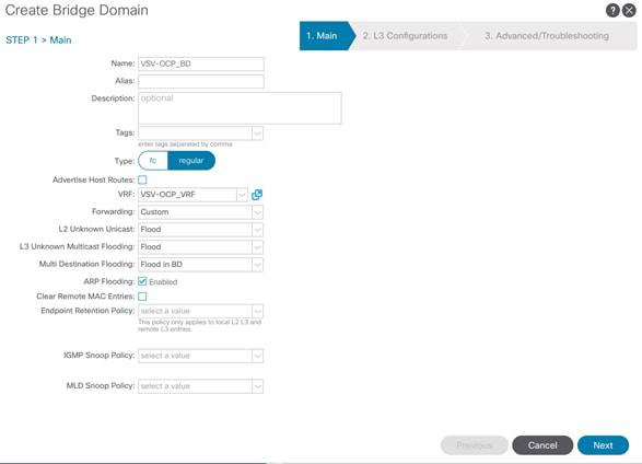
5. Click Next.
6. Under L3 Configurations, make sure Limit IP Learning to Subnet is selected and select EP Move Detection Mode – GARP based detection.
7. Select the + option to the far right of Subnets.
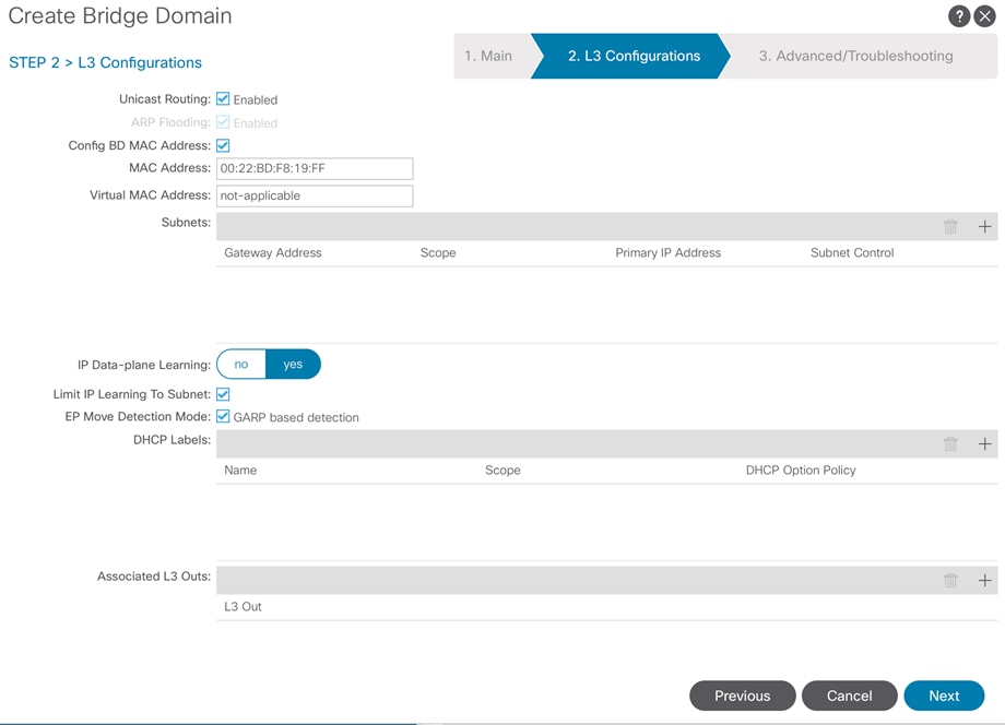
8. Provide the appropriate Gateway IP and mask for the subnet.
9. Select the Scope options for Advertised Externally and Shared between VRFs.
10. Click OK.
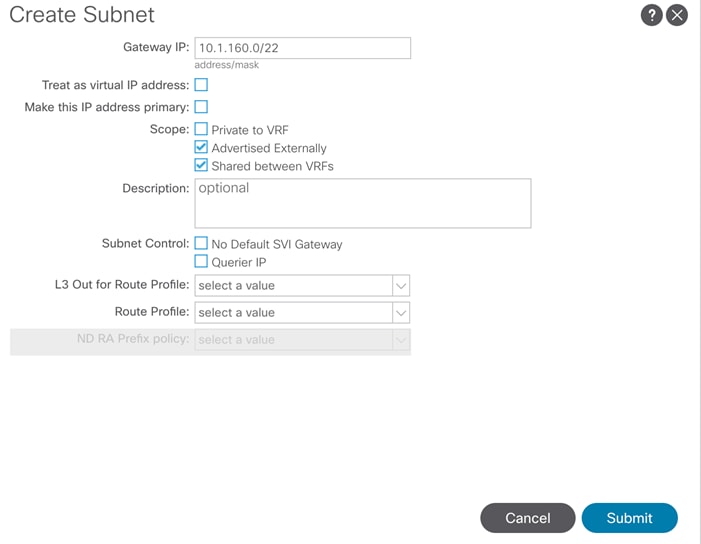
11. Click Submit.
Create Application Profile for OpenShift Container Platform
To create an application profile for Application-B, follow these steps:
In the left pane, expand tenant VSV-OCP, right-click Application Profiles and select Create Application Profile.
Name the Application Profile VSV-OCP_AP and click Submit to complete adding the Application Profile.
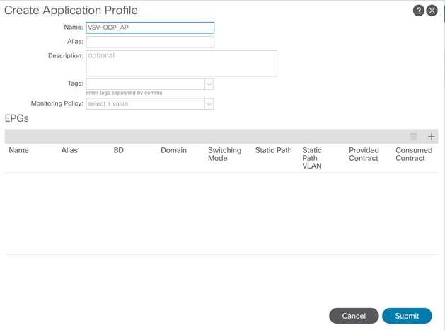
Create End Point Groups
To create the EPGs for Application-B, follow these steps:
EPG VSV-OCP_EPG
1. In the left pane expand Application Profiles > VSV-Application-B.
2. Right-click Application EPGs and select Create Application EPG.
Name the EPG VSV-OCP_EPG. Leave Intra EPG Isolation Unenforced.
From the Bridge Domain drop-down list, select VSV-OCP_BD.
3. Check the check box next to Associate to VM Domain Profiles.
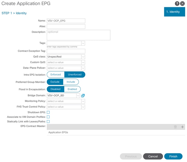
4. Click Finish.
5. Right-click the newly created EPG and select Add VMM Domain association.
6. From the Domain Profile drop-down list, select VMware domain. If customers have deployed both VDS and AVS domains, both the domain will be visible in the drop-down list as shown below. In this example, VMware domain for VDS is selected to deploy the EPG.
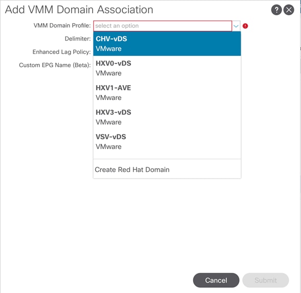
Change the Deployment Immediacy and Resolution Immediacy to Immediate.
7. Click Submit.
8. At this point, one new port-group should have been created on the VMware VDS. Log into the vSphere Web Client browse to Networking > VDS and verify.
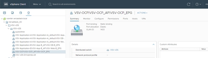
Configure Contracts
OCP-Tier to Shared L3 Out Contract
To enable OCP VMs to communicate outside the Fabric, Shared L3 Out contract defined in the Common Tenant will be consumed by the Web EPG. To enable Web VMs to access networks outside the fabric, follow these steps:
1. In the left navigation pane, expand Tenants > VSV-OCP > Application Profiles > VSV-OCP_AP > Application EPGs > EPG VSV-OCP_EPG
2. Right-click Contract and select Add Consumed Contract.
In the Add Consumed Contract window, from the Contract drop-down list, select Allow-Shared-L3Out.
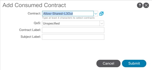
3. Click Submit to complete adding the Consumed Contract.
With the association of contracts to the OCP EPG, the OpenShift Container Platform application environment now has access to outside (L3Out) networks.
![]() If the nexus switches are deployed in Standalone mode in VersaStack, create the necessary port-group manually using vCenter on the VersaStack application (VDS) switch to support OCP traffic.
If the nexus switches are deployed in Standalone mode in VersaStack, create the necessary port-group manually using vCenter on the VersaStack application (VDS) switch to support OCP traffic.
VersaStack VMware vSphere Configuration
![]() Most of the vSphere related settings are explained in a previously published CVD and other technical documents published by Cisco and IBM. This section does provide some details about the configuration settings of the datastores, the networks, and the DRS rules used in our OCP test environment.
Most of the vSphere related settings are explained in a previously published CVD and other technical documents published by Cisco and IBM. This section does provide some details about the configuration settings of the datastores, the networks, and the DRS rules used in our OCP test environment.
vSphere iSCSI Datastores
iSCSI datastores are used as the underlying storage for the OCP nodes. The datastores are highly available at the storage level, protected by the RAID config of storage pool and are available to all ESXi hosts. Several datastores were configured but the total number will vary depending on the number of nodes and applications, and business requirements in terms of data protection policies and other data management and operational practices. In the FlashSystem storage, most of the data management features and policies are applied at the volume level, which is presented to vSphere for the creation of the datastore. It will be practical and efficient to use the same datastore for VMs that share the same set of data management requirements such as data replication or snapshots policies.
Five iSCSI-based datastores were configured and tested in our environment, as shown below. The datastores were associated with all four ESXi servers to enable highly available access to the underlying storage the VMs are deployed on and to support continuous operation in case of a vMotion operation when a VM is moved to a different ESXi host. Five iSCSI-based Datastores are listed in our test environment: Infra_datastore-1, Infra_datastore-2, Infra_datastore-3, Infra_Swap and OCP_infra-1, with the last one used for hosting the OCP nodes.
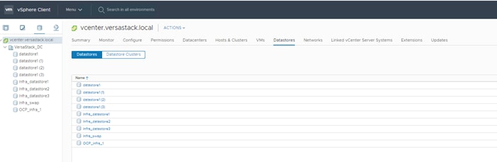
vSphere Networks
The vSphere environment was configured with the following network settings: VSV-OCP_EPG network was created as described in the above procedure and is associated with all four hosts on a distributed VSV-vDS managed by Cisco ACI and two port groups iSCSI-A and iSCSI-B on vSwitch iScsiBootvSwitch for managing iSCSI traffic respectively. Your IT best practices as well as recommendations from VMware, IBM and Cisco should be followed to meet the specific design for your environment.
To create two new port groups on the VersaStack iSCSI vSwitch (iScsiBootvSwitch) to support OCP Storage traffic for containers persistent volumes, follow these steps:
1. From the Host Client, select Networking.
2. In the center pane, select the Virtual switches tab.
Highlight the iScsiBootvSwitch line.
3. Select Add Networking
4. In Select connection type, select Virtual Machine Port Group for a Standard Switch and click Next.
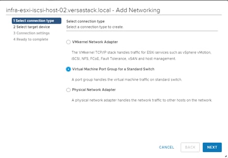
5. Keep the existing switch selected and click Next.
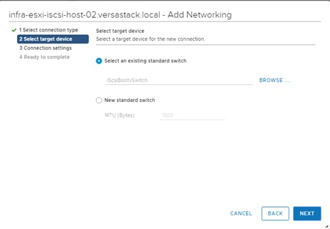
6. Type a Network label for the port group as iSCSI-A.
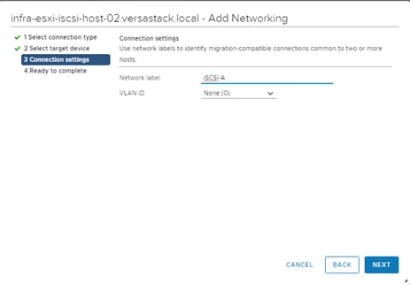
7. Click Next.
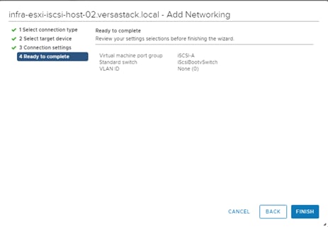
8. Click FINISH.
On the new created port group, Select the iSCSI-A row. Select Edit Settings to edit the properties of this port group.
1. Expand NIC teaming and select Yes to the right of Override failover order.
To the right of Failover order, select vmnic5 and select Mark unused.

Repeat the above procedure and create another port group for iSCSI fabric B traffic and name it as iSCSI-B. Make vmnic4 as unused on this new port group.
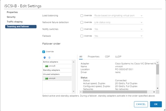
Setting Up vSphere Distributed Resource Scheduler (DRS) Rules
![]() The process of setting up DRS rules for the master nodes needs to be completed after the OCP cluster deployment. The procedure is included at this stage for continuity, since we are discussing the VMware configurations.
The process of setting up DRS rules for the master nodes needs to be completed after the OCP cluster deployment. The procedure is included at this stage for continuity, since we are discussing the VMware configurations.
In order for the OCP cluster to benefit from the underlying resiliency capabilities of the vSphere layer, DRS rules need to be defined and vMotion enabled as explained in the Design section. In our particular configuration we wanted to ensure that not more than one Master node will be hosted on an ESXi server. A similar rule can be set for the Management node.
Since the solution requires three Master nodes, it also means that at least three ESXi hosts are required, regardless of the required compute capacity. If we want to further protect the environment from a failure of one ESXi server, then a fourth ESXi needs to be included in the solution, as we have implemented in our test environment.
DRS and vMotion can be configured from the vCenter Configure tab for the cluster after the completion of the deployment of all the VMs that participate in the OCP cluster or at least those VMs that will be members in the DRS rule. It can also be configured upon the completion of the OCP installation. In either case it is recommended to test and confirm that the rules are properly in place.
To set up the vSphere DRS rules, follow these steps:
1. From the VersaStack-OCP cluster in the Configure option make sure that DRS is turned ON and should show as Fully Automated.
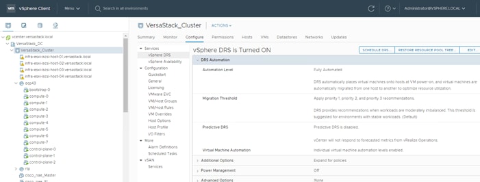
2. Click the VM/Host Rules under Configurations, then click Add to add a new rule.
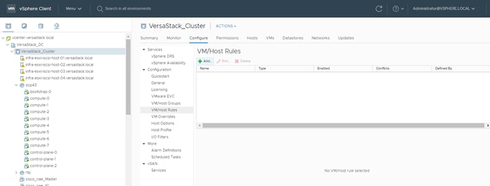
3. Select the three Master servers as members of the new rule then click OK.
4. Give the rule a meaningful name, make sure the Enable rule is checked and the type is Separate Virtual Machines, the click OK.
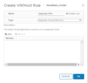
5. The rule is now in place and will be enforced. The desired behavior was validated during testing.
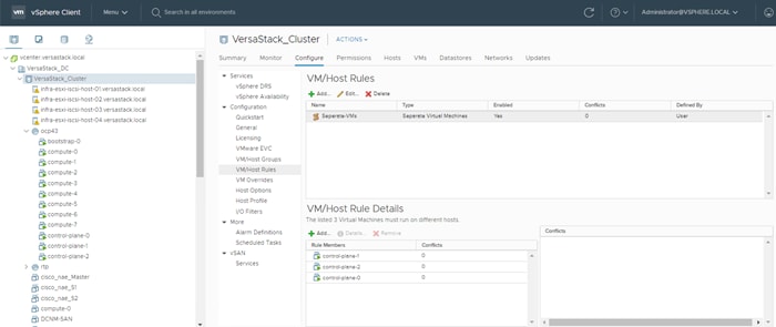
OpenShift Container Platform Installation and Configuration
![]() The installation of the OCP platform is a multi-step process that has to be carefully planned for each specific environment. There are several prerequisites for preparing the infrastructure and the nodes for the installation, and it is also important to recognize that the installation procedure may vary between the different versions of OCP.
The installation of the OCP platform is a multi-step process that has to be carefully planned for each specific environment. There are several prerequisites for preparing the infrastructure and the nodes for the installation, and it is also important to recognize that the installation procedure may vary between the different versions of OCP.
It is recommended to check the installation procedures published by Red Hat and match them to the specific release of OCP. See https://docs.openshift.com/container-platform/4.3/welcome/index.html.
Figure 39 Red Hat Documentation – Installing OCP
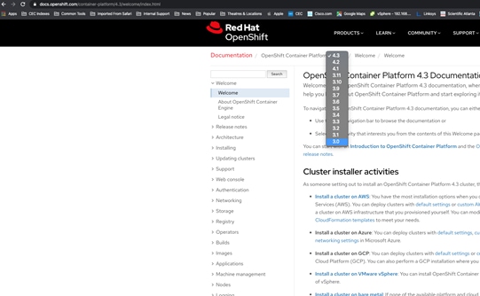
Prerequisites and Preparation Stage
As a reminder and as covered in the Solution Design section, we are deploying OCP version 4.3 with 7 nodes (Table 1). The lab setup of OpenShift was created as user-provisioned infrastructure using VMware vSphere 6.7 update 3 (6.7U3) deployed on VersaStack with Cisco ACI and IBM All-Flash Storage arrays.
The following sections give an overview of the cluster resources (such as number of virtual machines, configuration chosen, and network requirements) and infrastructure services (such as domain name server (DNS) and dynamic host configuration protocol (DHCP) and so on).
Infrastructure
Infrastructure components and related aspects must be deployed and configured according to best practices covered in previously published CVDs and other best practices from VMware, Cisco, Red Hat and IBM, and are not covered in detail in this document.
The following is a short description of these infrastructure components and aspects that must be addressed prior to installing OCP:
1. Storage, network and servers were deployed, connected and configured in HA settings to meet the requirements and were tested.
2. ESXi hosts were deployed and configured under the designated data center and cluster for OCP installation within an existing vCenter 6.7.
3. iSCSI datastores were configured and associated with all ESXi hosts.
4. DRS and vMotion was enabled.
5. Storage specific:
a. One or more pools create for OCP Persistent Volume Creation (PVC).
b. Optional Data Protection policies (data replication as well as snapshots policies) can be configured as desired.
c. Storage efficiency features were enabled.
6. Network specific:
a. IP addresses for nodes VMs.
b. Port Groups for OCP node network and storage connectivity as previously discussed.
Machine Requirements
Planning for compute resources is a required step as part of sizing the infrastructure for the OCP cluster. The Cisco UCS B-series M5 servers validated in the solution support broad range of Intel Xeon processors and can be loaded with up to 3TB of RAM, offering ample compute power to host significant workloads. Additional important sizing considerations are provided in the Solution Design section of this document. Table 1 provides the specification of each node VM according to the environment implemented for this CVD. For a cluster that contains user-provisioned infrastructure, you must deploy all of the required machines.
The smallest OpenShift Container Platform clusters require the following hosts:
· One bootstrap/boot node
· Three control plane/master nodes
· At least two compute/worker nodes
![]() The cluster requires the bootstrap machine to deploy the OpenShift Container Platform cluster on the three control plane machines. You can remove the bootstrap machine after the cluster installation.
The cluster requires the bootstrap machine to deploy the OpenShift Container Platform cluster on the three control plane machines. You can remove the bootstrap machine after the cluster installation.
The bootstrap node, master nodes and compute nodes must use Red Hat Enterprise Linux CoreOS (RHCOS) as the operating system.
![]() Note that RHCOS is based on Red Hat Enterprise Linux 8 and inherits all of its hardware certifications and requirements. See Red Hat Enterprise Linux technology capabilities and limits.
Note that RHCOS is based on Red Hat Enterprise Linux 8 and inherits all of its hardware certifications and requirements. See Red Hat Enterprise Linux technology capabilities and limits.
Minimum Resource Requirements
Each cluster machine must meet the following minimum requirements as listed in Table 4.
Table 4 Hardware Configuration for Cluster nodes
| Machine |
Operating System |
vCPU |
RAM |
Storage |
Comment |
| Bootstrap |
RHCOS |
4 |
16 GB |
120GB |
Bootstrap node |
| Control plane |
RHCOS |
4 |
16 GB |
120GB |
Control plane/Master nodes |
| Compute |
RHCOS |
2 |
8 GB |
120GB |
Compute/Worker nodes |
| Mgmt-host |
RHEL 7.5+ |
2 |
8GB |
50 GB |
Management/ Automation node (Not part of OCP Cluster) |
Certificate Signing Requests Management
Because the OCP cluster has limited access to automatic machine management when deployed on user provisioned infrastructure, we must provide a mechanism for approving cluster certificate signing requests (CSRs) after installation. The kube-controller-manager only approves the kubelet client CSRs. The machine-approver cannot guarantee the validity of a serving certificate that is requested by using kubelet credentials because it cannot confirm that the correct machine issued the request. You must determine and implement a method of verifying the validity of the kubelet serving certificate requests and approving them. The Certificate signing requests management has not being implemented during this validation, we have manually approved all the CSRs after installation, the CSR approval procedure is covered in later sections of this document.
OpenShift Build/Mgt Server
The build and management server should be configured as a virtual machine running within the virtualization environment which will be used as a management host to install the OpenShift Container Platform and hosts all the required software and files need for the cluster deployment. The virtual machine should be configured with VMware high availability to ensure it is recovered in the event of an ESXi failure. Higher levels of high availability are not necessary for the build and management server since it is not critical to the functioning of the cluster but only the administration of the cluster.
The operating system can be any provided that it is compatible with the list of software to be installed, Red Hat Enterprise Linux 7.6 has been used in this case in the lab.
OCP Network Connectivity Requirements
All the Red Hat Enterprise Linux CoreOS (RHCOS) machines require network in initramfs during boot to fetch Ignition config files from the Machine Config Server. During the initial boot, the machines require either a DHCP server or that static IP addresses be set in order to establish a network connection to download their Ignition config files. We used DHCP to initially assign IP addresses to the cluster nodes and have got the static IPs assigned using Terraform scripts during installation.
During the installation an internal network is configured, to make this possible a virtual switch is installed and configured automatically. This switch makes sure that the internal network is forwarded from the public network. OpenShift Container Platform has a built-in DNS to resolve the hosts created internally. This DNS is in charge of managing the port forwarding for the public IP into the internal network such as for resolving the internal services IP addresses.
Internet Access
While installing all the prerequisites needed to deploy the OpenShift Container Platform configuration, all the nodes must have Internet access to register each node and to install every dependency needed.
During installation, the Internet access is used to complete the following actions:
· Download the installation program itself
· Obtain the packages required to install and update the cluster
· Perform subscription management
Load Balancer
Required to provide load balancing capabilities for bootstrap node, OpenShift compute nodes running the ingress router and OpenShift master nodes. The bootstrap node configuration should be removed once the installation is completed. The load balancers should be configured in a highly available configuration for production deployments.
Application traffic passes through the Red Hat OpenShift Container Platform Router on its way to the container processes. The Red Hat OpenShift Container Platform Router is a reverse proxy service container that multiplexes the traffic to multiple containers making up a scaled application running inside Red Hat OpenShift Container Platform. The load balancer used by infrastructure nodes acts as the public view for the Red Hat OpenShift Container Platform applications.
Passwordless SSH Configuration
For intra-cluster communication and for logging onto the cluster nodes, ssh-keys are used. These were generated on management host using the ssh-keygen command. The contents of the id_rsa.pub file is later incorporated in the sshKey section of the install-config.yaml file used for cluster creation.
Deployment Process Overview
This section describes the Red Hat OpenShift 4.3 deployment process on VersaStack using Terraform. The three-step process includes:
1. Setting up the user provisioned infrastructure services:
· Configure DNS
· Configure Load Balancer
· Configure Web Server
· Configure DHCP
· Prepare the deployment host, installing Terraform and other software dependencies
2. OpenShift Container Platform Deployment:
· Install Terraform
· Generate SSH private key
· Obtain the installation program
· Create the installation configuration file
· Create manifest and ignition config files
· Create RHCOS VM template
· Install OCP CLI
· Prepare and configure terraform installer with config files
· Run terraform scripts to Install OpenShift Container Platform Cluster
3. IBM CSI driver for block storage installation and configuration
![]() Make sure that all the components in your infrastructure such as the vCenter, ESXi servers and all the Infrastructure services, Management host and the OCP nodes are synced to the same NTP server and without having any drift in the time configuration. This is critical to avoid any issues with the OCP installation.
Make sure that all the components in your infrastructure such as the vCenter, ESXi servers and all the Infrastructure services, Management host and the OCP nodes are synced to the same NTP server and without having any drift in the time configuration. This is critical to avoid any issues with the OCP installation.
Deployed Topology
The lab topology is shown in Figure 38. The host’s configuration, usage, and IP addresses are shown in Table 5. The bootstrap machine is first configured to boot using the Ignition configuration files using Terraform followed by the master and worker nodes.
Table 5 Deployed node information
| Hostname |
IP address |
Comment |
| bootstrap-0 |
10.1.162.10 |
Bootstrap node |
| control-plane-0 |
10.1.162.11 |
Master Node |
| control-plane-1 |
10.1.162.12 |
Master Node |
| control-plane-2 |
10.1.162.13 |
Master Node |
| compute-0 |
10.1.162.14 |
Worker Node |
| compute-1 |
10.1.162.15 |
Worker Node |
| compute-2 |
10.1.162.16 |
Worker Node |
| compute-3 |
10.1.162.17 |
Worker Node |
![]() The terms compute and worker node as well as the master and control plane are used interchangeably across the document. Table 5 lists the number of nodes deployed initially before scaling the OCP cluster.
The terms compute and worker node as well as the master and control plane are used interchangeably across the document. Table 5 lists the number of nodes deployed initially before scaling the OCP cluster.
All service nodes were configured as VMs on the VersaStack ESXi cluster. The HTTP, DHCP and DNS services were leveraged during the OCP installation. The Mgmt-host is the management host used to run the openshift-installer program to create and encode the required Ignition configuration files and to host the terraform platform for automating the installation.
OpenShift Container Platform requires a fully functional DNS server in the environment. A set of records must be configured in the DNS to provide name resolution for hosts and containers running on the platform. Optionally, you we can also configure a wildcard DNS record that points to the load balancer or routers to avoid the need to update your DNS configuration when new routes are added.
The following DNS records are required for an OpenShift Container Platform cluster that uses user-provisioned infrastructure. In each record, <cluster_name> is the cluster name and <base_domain> is the cluster base domain that you specify in the install-config.yaml file. A complete DNS record takes the following form: <component>.<cluster_name>.<base_domain>.
The DNS and DHCP configuration used in the validation lab are listed in “Appendix: DNS file” and “Appendix: DHCP file”
The required bootstrap Ignition configuration files and the raw installation images were hosted on a locally configured web server used as the Machine Config Server. The web server configuration is listed in “Appendix: HTTP file”.
Table 6 lists the details of the cluster name, domain name, and subdomain name used in the lab setup.
| Entity |
Description |
| Base Domain |
vs-ocp.com |
| Openshift Cluster Name |
rtp |
Red Hat OpenShift Container Platform 4.3 Installation Overview
This section explains the Red Hat OpenShift planning, considerations, and installation guidelines.
Install Infrastructure Services
This section describes the installation sequence and configuration procedure flow for the various infrastructure services and management host used for validating the solution. All the required services have been installed on RHEL 7.6 virtual machines deployed on VersaStack, customers can also use their choice of services or existing services if available in their environments.
To create a new virtual machine, follow these steps:
1. Login to VMware vCenter web client.
Right-click the <VersaStack_Cluster> cluster and select New Virtual Machine.
2. Select Create a new virtual machine and click Next.
Enter a name for the virtual machine, select the <VersaStack_DC> datacenter for VM deployment.
3. Click Next.
Select <VersaStack_Cluster> cluster for the virtual machine, click Next.
4. Select datastore and click Next.
5. Select the compatibility from the drop-down list and click Next.
6. Select a guest operating system (RHEL 7) and click Next.
7. Customize the Virtual Machine Hardware according to requirements. Connect the operating system from the pre-loaded Content Library.
![]() Optionally, the operating System disk can be mounted after the virtual machine is created for the OS installation.
Optionally, the operating System disk can be mounted after the virtual machine is created for the OS installation.
8. Click Finish to complete the virtual machine creation.
9. Boot the virtual machine and access the virtual machine console from VMware web client.
10. Continue with the operating system installation process.
11. Configure Network settings.
12. Complete the installation and power on the virtual machine.
13. Clone the newly created VM in to multiple VMs to host different services. As part of the solution validation, 5 VMs were used one for each service including management host for terraform and ignition file creation
14. Once the installation is completed, register the nodes using following command.
# subscription-manager register
15. Enable the Red Hat Enterprise Linux 7 server repository as follows:
# subscription-manager repos --enable=rhel-7-server-rpms
Installing and Configuring a DNS server (named)
A domain name service (DNS) is required for access to the cluster as discussed earlier. This should use existing domain name servers for production deployments. The domain name server (named) available with the RHEL distribution was used to create a DNS server. The configuration files used for creating the DNS server are listed in in section DNS Forward Lookup Zone File of the Appendix.
![]() Make sure you verify all the forward and reverse look up zones entries carefully if using any DNS server other than (named) and if the zones are auto populated. We noticed that sometimes reverse zones create issues with auto population of records and the OCP installation fails due to this reason.
Make sure you verify all the forward and reverse look up zones entries carefully if using any DNS server other than (named) and if the zones are auto populated. We noticed that sometimes reverse zones create issues with auto population of records and the OCP installation fails due to this reason.
To install and configure the DNS server, follow these steps:
1. Install the bind operating system package using yum or rpm command:
# yum -y install bind bind-utils
Update the /etc/named.conf and the forward and reverse zone configuration files as listed in section /etc/name.conf of the Appendix.
2. Start or Restart the server and enable the named service for system startup:
# systemctl restart named
# systemctl enable named
Add the following firewall rules to allow clients connection to DNS server for name resolution:
# firewall-cmd --permanent --add-port=53/udp
# firewall-cmd –reload
or the Firewall can be stopped and disabled for system startup using the following commands:
# systemctl stop firewalld
# systemctl disable firewalld
3. The DNS needs to be updated with the following values:
| Name |
Record |
Description |
| Kubernetes API
|
api.<cluster_name>.<base_domain>. |
This DNS A/AAAA or CNAME record must point to the load balancer for the control plane machines. This record must be resolvable by both clients external to the cluster and from all the nodes within the cluster. |
| api-int.<cluster_name>.<base_domain>. |
This DNS A/AAAA or CNAME record must point to the load balancer for the control plane machines. This record must be resolvable from all the nodes within the cluster. |
|
| Application Routes |
*.apps. <cluster_name>.<base_name>. |
A wildcard DNS A/AAAA or CNAME record that points to the load balancer that targets the machines that run the Ingress router pods, which are the worker nodes by default. This record must be resolvable by both clients external to the cluster and from all the nodes within the cluster. |
| etcd
|
etcd-<index>.<cluster_name>.<base_name>. |
OpenShift Container Platform requires DNS A/AAAA records for each etcd instance to point to the control plane machines that host the instances. The etcd instances are differentiated by <index> values, which start with 0 and end with n-1, where n is the number of control plane machines in the cluster. The DNS record must resolve to a unicast IPv4 address for the control plane machine, and the records must be resolvable from all the nodes in the cluster. |
| _etcd-server-ssl._tcp. <cluster_name>.<base_name>. |
For each control plane machine, OpenShift Container Platform also requires an SRV DNS record for etcd server on that machine with priority 0, weight 10 and port 2380. |
4. In table (above), the following variables are used;
<index> - the number of the master node. Starting at 0. For example, the first master node would be etcd-0.
<cluster_name> - the domain name used for the cluster.
<base_name> - the base domain name for the intranet the cluster is located within.
| Entity |
Description |
| Base Domain: <base_name> |
vs-ocp.com |
| Openshift Cluster Name: <cluster_name> |
rtp |
Installing and Configuring a DHCP Server (dhcp)
The dynamic host configuration protocol server (dhcp) available with the RHEL distribution was used to create a DHCP server. Dynamic IP address allocation is required during the creation of cluster nodes by Terraform to access the ignition files. Once the connectivity is established and the VM gets configured, the static IP address gets assigned based on the information from machineconfig file for the specific node.
To install and configure a DHCP server, follow these steps:
1. Install the dhcp operating system package using yum/rpm command:
# yum install dhcp
Configure the DHCP server by updating the configuration file (/etc/dhcp/dhcpd.conf) as listed in section /etc/dhcp/dhcpd.conf of the Appendix. The parameters and IP subnet information needs to be updated based on the customer environment.
2. Start or Restart the server and enable the dhcpd service for system startup:
# systemctl restart dhcpd
# systemctl enable dhcpd
Add the following firewall rules to allow clients connection to DHCP server:
# firewall-cmd --permanent --add-service=dhcp
# firewall-cmd –reload
or the Firewall can be stopped and disabled for system startup using the following commands:
# systemctl stop firewalld
# systemctl disable firewalld
Installing and Configuring a Web Server (Apache httpd)
The installation requires a web server, no specific configuration is required other than a directory to hold the ignition files. The Apache web server (httpd) available with the RHEL distribution was used to create an HTTP server.
![]() Default the default web server port is 80, we changed it to 8080 on the web server deployed for validation. Refer to the /etc/httpd/conf/httpd.conf section in the Appendix for implementation details.
Default the default web server port is 80, we changed it to 8080 on the web server deployed for validation. Refer to the /etc/httpd/conf/httpd.conf section in the Appendix for implementation details.
1. Install the httpd operating system package using the yum or rpm command:
# yum install httpd
Update the configuration file (/etc/httpd/conf/httpd.conf) as listed in section /etc/httpd/conf/httpd.conf of the Appendix.
2. Start or Restart the server and enable the httpd service:
# systemctl restart httpd
# systemctl enable httpd
3. Add the following firewall rules to allow clients connection to HTTP server:
# firewall-cmd --zone=public --permanent --add-service=http
# firewall-cmd –reload
![]() If port 8080 is used on the HTTP server, the TCP port 8080 can be opened in the firewall using the following command:
If port 8080 is used on the HTTP server, the TCP port 8080 can be opened in the firewall using the following command:
# firewall-cmd --zone=public --permanent --add-port 8080/tcp
![]() Optionally, the firewall can be stopped and disabled for system startup using the following commands:
Optionally, the firewall can be stopped and disabled for system startup using the following commands:
# systemctl disable firewalld
Installing and Configuring the Load Balancer (haproxy)
The validated environment used an external load balancer running HAproxy to offer a single-entry point for the many Red Hat OpenShift Container Platform components. Organizations can provide their own currently deployed load balancers in the event that the service already exists.
The load balancer (haproxy) available with the RHEL distribution was used to create the haproxy server. The configuration files used for creating the haproxy server are listed in section Appendix: haproxy file.
To install and configure the load balancer, follow these steps:
1. Install the haproxy operating system package using the yum or rpm command:
# yum install haproxy
2. Update the configuration files (/etc/haproxy/haproxy.cfg), as listed in section /etc/haproxy/haproxy.cfg of the Appendix.
3. Start or Restart the haproxy service:
# systemctl restart haproxy
# systemctl enable haproxy
Add the following firewall rules to allow clients connection to access HAProxy server:
# firewall-cmd --permanent --add-service=haproxy
# firewall-cmd --reload
Optionally, the Firewall can be stopped and disabled for system startup using the following commands:
# systemctl stop firewalld
# systemctl disable firewalld
![]() If your haproxy service does not start and SELinux is enabled, run the following command to allow haproxy to bind to non-standard ports: setsebool -P haproxy_connect_any on
If your haproxy service does not start and SELinux is enabled, run the following command to allow haproxy to bind to non-standard ports: setsebool -P haproxy_connect_any on
4. The output of the following commands should display the status as “Active: active (running)”, without any errors.
5. The load balancer needs to be configured with the values as follows:
| Description |
Incoming Port |
Mode |
Destination |
Dest. Port |
Balance |
| OpenShift Admin |
6443 |
TCP |
Master Nodes |
6443 |
Source |
| OpenShift Installation (Removed once built) |
22623 |
TCP |
Bootstrap and Master Nodes |
22623 |
Source |
| OpenShift Application Ingress |
80 |
TCP |
Worker Nodes |
80 |
Source |
| 443 |
TCP |
Worker Nodes |
443 |
Source |
![]() The status of the installed services can be verified using the following commands before proceeding with the OpenShift Container Platform cluster installation:
The status of the installed services can be verified using the following commands before proceeding with the OpenShift Container Platform cluster installation:
# systemctl status httpd
# systemctl status dhcpd
# systemctl status named
# systemctl status haproxy
Install Terraform
Terraform is an Infrastructure as Code tool for building, changing, and versioning infrastructure safely and efficiently. Other tools like Ansible have a focus on automating the installation and configuration of the software. Terraform automates provisioning of the infrastructure itself.
Terraform has been used for the fully automated VM provisioning for OCP cluster nodes.
![]() Currently only version 11.x of terraform is working with the installer github template.
Currently only version 11.x of terraform is working with the installer github template.
Terraform consists of the following components:
· Configuration files(.tf). Terraform uses its own configuration language, designed to allow concise descriptions of infrastructure. The Terraform language is declarative, describing an intended goal rather than the steps to reach that goal.
· Terraform binary (executable) file, is written and compiled in GO language. To install Terraform, find the appropriate package for your system and download it from https://releases.hashicorp.com/terraform/0.11.14/
· Terraform state file (.tfstate), is a JSON file with running configuration.
To install Terraform, run the following commands on the management host:
# mkdir /terraform
# cd /terraform/
# export TERRAFORM_VERSION=0.11.14
# curl -O -L https://releases.hashicorp.com/terraform/#{TERRAFORM_VERSION}/terraform_#{TERRAFORM_VERSION}_linux_amd64.zip
# unzip terraform_#{TERRAFORM_VERSION}_linux_amd64.zip -d ~/bin/
# terraform -v
Terraform v0.11.14
Generating an SSH Private Key and Adding It to the Agent
In order to perform installation debugging or disaster recovery on the OpenShift cluster, provide an SSH key to both ssh-agent and to the installation program.
This key can be used to SSH into the master nodes as the user core. During cluster deployment, the key is added to the core user’s ~/.ssh/authorized_keys list and helps password less entry between the cluster nodes.
To create SSH key for password-less authentication on your management host, follow these steps:
Run the following command, Specify the path and file name, such as ~/.ssh/id_rsa, of the SSH key:
# ssh-keygen -t rsa -b 4096 -N '' -f <path>/<file_name>
Example: # ssh-keygen -t rsa -b 4096 -N '' -f ~/.ssh/id_rsa
Generating public/private rsa key pair.
/root/.ssh/id_rsa already exists.
Overwrite (y/n)? y
Your identification has been saved in /root/.ssh/id_rsa.
Your public key has been saved in /root/.ssh/id_rsa.pub.
The key fingerprint is:
SHA256:+2xsnxhhhrWf7JHJ/43//AgMqsOlPv768HImChYfTjw root@192.168.160.244.localdomain
The key's randomart image is:
+---[RSA 4096]----+
| |
| |
| . |
| . o . |
| . E S * |
| = o .= B + |
| o o..oo.. @ |
| . . B+oo++ = +.|
| .+=@+o+.+ +oX|
+----[SHA256]-----+
Running the above command generates an SSH key that does not require a password in the location that you specified. (Mgmt-Host)
4. Start the ssh-agent process as a background task:
# eval "#(ssh-agent -s)"
Example: eval "#(ssh-agent -s)"
Agent pid 23694
Specify the path and file name for your SSH private key, such as ~/.ssh/id_rsa
# ssh-add <path>/<file_name>
Example: # ssh-add ~/.ssh/id_rsa
Identity added: /root/.ssh/id_rsa (/root/.ssh/id_rsa)
![]() During the OpenShift Container Platform installation, the SSH public key needs to be provided to the installation program. Since you are installing the cluster on infrastructure that you provisioned, you must provide this key to the cluster’s machines.
During the OpenShift Container Platform installation, the SSH public key needs to be provided to the installation program. Since you are installing the cluster on infrastructure that you provisioned, you must provide this key to the cluster’s machines.
Obtaining the Installation Program
Prior to installing OpenShift Container Platform, the installation file needs to be downloaded on to the management host.
To obtain installation program, follow these steps:
1. Access the Infrastructure Provider page on the Red Hat OpenShift Cluster Manager site. If you have a Red Hat account, log in with your credentials. If you do not, create an account.
2. Navigate to the page for your installation type https://mirror.openshift.com/pub/openshift-v4/dependencies/rhcos/4.3/latest/ download the installation program for your operating system, and place the file in the directory where you will store the installation configuration files.
You can download all the required elements at this time for efficiency. The following is required for installation:
# ls openshift-client-linux.tar.gz pull-secret.txt
openshift-install-linux.tar.gz rhcos-4.3.8-x86_64-vmware.x86_64.ova
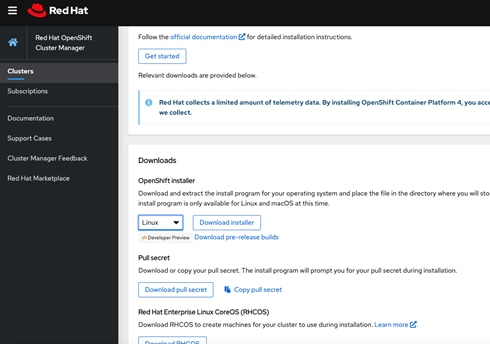
![]() The installation program creates several files on the computer that are required to install the cluster. You need to keep both the installation program and the files that the installation program creates after finishing installing the cluster.
The installation program creates several files on the computer that are required to install the cluster. You need to keep both the installation program and the files that the installation program creates after finishing installing the cluster.
3. Extract the installation program. For example, on management host, run the following command:
#tar xvf openshift-install-linux.tar.gz
README.md
openshift-install
From the Pull Secret section on the Red Hat OpenShift Cluster Manager site, download your installation pull secret as a .txt file. This pull secret allows you to authenticate with the services that are provided by the included authorities, including Quay.io, which serves the container images for OpenShift Container Platform components.
Create the Installation Configuration File
For installations of OpenShift Container Platform that use user-provisioned infrastructure, we must manually generate the installation configuration file after the OCP installation program and the access token for the cluster are obtained.
To create installation configuration file, follow these steps:
1. Create an installation directory on the management host to store your required installation assets in:
# mkdir <installation_directory>
Example: # mkdir ocp43
You must create a directory. Some installation assets, like bootstrap X.509 certificates have short expiration intervals, so you must not reuse an installation directory. If you want to reuse individual files from another cluster installation, you can copy them into your directory. However, the file names for the installation assets might change between releases. Use caution when copying installation files from an earlier OpenShift Container Platform version.
Customize the following install-config.yaml file template and save it in the <installation_directory>.
Manually create a file and name this configuration file install-config.yaml.
# touch install-config.yaml
For the install-config.yaml, the following input might be required:
· base domain
· OCP cluster id
· OCP pull secret
· ssh public key (~/.ssh/id_rsa.pub)
· vCenter host
· vCenter user
· vCenter password
· vCenter datacenter
· vCenter datastore
Sample install-config.yaml file for VMware vSphere
Customize the install-config.yaml file to specify more details about your OpenShift Container Platform cluster’s platform or modify the values of the required parameters shown in in red font below to suit your environment.
apiVersion: v1
baseDomain: vs-ocp.com
compute:
- hyperthreading: Enabled
name: worker
replicas: 0
controlPlane:
hyperthreading: Enabled
name: master
replicas: 3
metadata:
name: <rtp.vs-ocp.com>
platform:
vsphere:
vcenter: vcenter.versastack.local
username: administrator@vsphere.local
password: PASSWORD
datacenter: VersaStack_DC
defaultDatastore: OCP_Infra_1
fips: false
pullSecret: '{"auths": ...}'
sshKey: 'ssh-ed25519 AAAA...'
Care should be taken while populating the contents of install-config.yaml file with PullSecret and sshKey information, verify that no special characters such as line breaks etc are not copied to the file in error.
The required parameters displayed in red in the file (above) are described below in the same order as they are listed in the file.
baseDomain: The base domain of the cluster. All DNS records must be sub-domains of this base and include the cluster name.
hyperthreading: Whether to enable or disable simultaneous multithreading, or hyperthreading. By default, simultaneous multithreading is enabled to increase the performance of your machines' cores.
replicas: You must set the value of the replicas parameter to 0. This parameter controls the number of workers that the cluster creates and manages for you, which are functions that the cluster does not perform when you use user-provisioned infrastructure. We will manually deploy worker machines for the cluster to use before you finish installing OpenShift Container Platform.
replicas: The number of control plane machines that you add to the cluster. Because the cluster uses this value as the number of etcd endpoints in the cluster, the value must match the number of control plane machines that you deploy
name: cluster name that you specified in your DNS records.
vcenter: The fully qualified host name or IP address of the vCenter server.
username: The name of the user for accessing the server. This user must have at least the roles and privileges that are required for static or dynamic persistent volume provisioning in vSphere.
password: The password associated with the vSphere user.
datacenter: The vSphere datacenter.
defaultDatastore: The default vSphere datastore to use.
fips: Whether to enable or disable FIPS mode. By default, FIPS mode is not enabled. If FIPS mode is enabled, the Red Hat Enterprise Linux CoreOS (RHCOS) machines that OpenShift Container Platform runs on bypass the default Kubernetes cryptography suite and use the cryptography modules that are provided with RHCOS instead.
pullSecret: The pull secret that is obtained from the Pull Secret page on the Red Hat OpenShift Cluster Manager site. This pull secret allows you to authenticate with the services that are provided by the included authorities, including Quay.io, which serves the container images for OpenShift Container Platform components.
sshKey: The public portion of the default SSH key for the core user in Red Hat Enterprise Linux CoreOS (RHCOS)
1. Back up the install-config.yaml file so that it can be used to install multiple clusters.
2. The install-config.yaml file is consumed during the next step of the installation process. The file can be backed up now using the following command.
# cd <installation_directory>
# cp install-config.yaml install-config.`date '+%s'`.bak
Installing and Creating the Ignition Configuration Files on Mgmt-host
The openshift-installer obtained from OpenShift Infrastructure Providers was run to create the Ignition Configuration files. The openshift-installer expects the YAML formatted file that was created in the above step (install-config.yaml) in order to generate the cluster configuration information.
To prepare the OCP Cluster installation, follow these steps:
Creating the Kubernetes Manifest and Ignition Config Files
Since we must modify some cluster definition files and manually start the cluster machines, we must generate the Kubernetes manifest and Ignition config files that the cluster needs to make its machines.
1. Generate the Kubernetes manifests for the cluster which defines the objects bootstrap nodes will have to create initially:
# ./openshift-install create manifests --dir=<installation_directory>
INFO Consuming Install Config from target directory
WARNING Making control-plane schedulable by setting MastersSchedulable to true for Scheduler cluster settings
![]() Since we create our own compute machines later in the installation process, we can safely ignore this warning.
Since we create our own compute machines later in the installation process, we can safely ignore this warning.
For <installation_directory, ex ocp43>, specify the installation directory that contains the install-config.yaml file that was created, else change into the directory.
![]() The Ignition config files that the installation program generates contain certificates that expire after 24 hours. You must complete your cluster installation and keep the cluster running for 24 hours in a non-degraded state to ensure that the first certificate rotation has finished.
The Ignition config files that the installation program generates contain certificates that expire after 24 hours. You must complete your cluster installation and keep the cluster running for 24 hours in a non-degraded state to ensure that the first certificate rotation has finished.
Modify the manifests/cluster-scheduler-02-config.yml Kubernetes manifest file to prevent Pods from being scheduled on the control plane machines:
· Open the manifests/cluster-scheduler-02-config.yml file.
Locate the “masters Schedulable” parameter and set its value to “False”.
· Save and exit the file.
apiVersion: config.openshift.io/v1
kind: Scheduler
metadata:
creationTimestamp: null
name: cluster
spec:
mastersSchedulable: False
policy:
name: ""
status: {}
![]() Currently, due to a Kubernetes limitation, router Pods running on control plane machines will not be reachable by the ingress load balancer. This step might not be required in a future minor version of OpenShift Container Platform.
Currently, due to a Kubernetes limitation, router Pods running on control plane machines will not be reachable by the ingress load balancer. This step might not be required in a future minor version of OpenShift Container Platform.
2. Create the Ignition config files. Ignition is the utility that is used by RHCOS to manipulate disks during initial configuration. It completes common disk tasks, including partitioning disks, formatting partitions, writing files, and configuring users. On first boot, Ignition reads its configuration from the installation media or the location specified and applies the configuration to the machines.
# ./openshift-install create ignition-configs --dir=<installation_directory>
INFO Consuming Master Machines from target directory
INFO Consuming Common Manifests from target directory
INFO Consuming Openshift Manifests from target directory
INFO Consuming OpenShift Install (Manifests) from target directory
INFO Consuming Worker Machines from target directory
![]() For <installation_directory>, specify the same installation directory, if you are executing the command from the installation directory, --dir option is not required.
For <installation_directory>, specify the same installation directory, if you are executing the command from the installation directory, --dir option is not required.
3. The following files are generated in the directory:
# tree
.
├── auth
│ ├── kubeadmin-password
│ └── kubeconfig
├── bootstrap.ign
├── master.ign
├── metadata.json
└── worker.ign
![]() The ignition files are valid for 24 hours - so if the installation takes longer than 24 hours due to any reason, new ignition files need to be generated.
The ignition files are valid for 24 hours - so if the installation takes longer than 24 hours due to any reason, new ignition files need to be generated.
Copy Ignition Files to the HTTP Server
To copy the ignition files to the HTTP server, follow these steps:
Change permissions and copy the generated bootstrap.ign file to HTTP server, ensure that the file can be downloaded with http:
# chmod 777 bootstrap.ign
# scp bootstrap.ign root@10.1.162.3:/var/www/html/
4. Verify, if download is successful from your http server using following command:
# curl -I http://10.1.162.3:8080/bootstrap.ign
HTTP/1.1 200 OK
...
Creating Red Hat Enterprise Linux CoreOS (RHCOS) VM Template in vSphere
Prior to installing the OCP cluster on VMware vSphere, you need to create RHCOS machines on vSphere hosts for it to use.
To create the VM template using RHCOS OVA, follow these steps:
1. Obtain the RHCOS OVA image from the Product Downloads page on the Red Hat customer portal or the RHCOS image mirror page, https://mirror.openshift.com/pub/openshift-v4/dependencies/rhcos/4.3/latest/
![]() The RHCOS images might not change with every release of OpenShift Container Platform. You must download an image with the highest version that is less than or equal to the OpenShift Container Platform version that you install. Use the image version that matches your OpenShift Container Platform version if it is available.
The RHCOS images might not change with every release of OpenShift Container Platform. You must download an image with the highest version that is less than or equal to the OpenShift Container Platform version that you install. Use the image version that matches your OpenShift Container Platform version if it is available.
The file name contains the OpenShift Container Platform version number in the format rhcos-<version>-vmware.<architecture>.ova. (ex: rhcos-4.3.8-x86_64-vmware.x86_64.ova)
2. In the vSphere Client, create a template for the OVA image.
3. In the following steps, we use the same template for all of your cluster machines when we provision the VMs using Terraform
From the Hosts and Clusters tab, right-click your cluster’s name <VersaStack_Cluster> and click Deploy OVF Template.
4. On the Select an OVF tab, specify the name of the RHCOS OVA file that you downloaded under Local file.
5. On the Select a name and folder tab, set a Virtual machine name, such as RHCOS, click the name of your vSphere cluster.
6. On the Select a compute resource tab, click the name of your vSphere cluster.
7. On the Select storage tab, configure the storage options for your VM.
8. Select Thin Provision.
Select the datastore <OCP_Infra_1> that you specified in your install-config.yaml file
On the Select network tab, specify the network <VS-OCP-EPG> that we configured for the OCP cluster.
9. As we will use the same template for all cluster machine types, we do not specify values on the Customize template tab.
10. Verify the selected parameters and click Finish.
Once the VM is deployed, it needs to be converted it into a template <rhcos-4.3.0>.
11. Right-click the newly created VM, and in the resulting context menu, select Template > Convert to Template.
12. Click Yes to proceed with the template creation by confirming at the displayed message.
Installing the CLI by Downloading the Binary
Install the CLI on the management host to interact with OpenShift Container Platform using a command line interface.
![]() If an earlier version of oc command utility exists, you cannot use it to complete all of the commands in OpenShift Container Platform 4.3. Download and install the new version of oc.
If an earlier version of oc command utility exists, you cannot use it to complete all of the commands in OpenShift Container Platform 4.3. Download and install the new version of oc.
1. Download the Command-line Tools from the following mirror site https://mirror.openshift.com/pub/openshift-v4/clients/ocp/4.3.8/.
2. Click the folder for your operating system (Linux in your case) and architecture and click the compressed file.
3. Save the file for your operating system (Linux in your case) and architecture to your file system on the management host.
4. Extract the compressed file.
# tar xvf openshift-client-linux.tar.gz
README.md
oc
kubectl
Copy oc and kubectl executable files to a directory that is on your PATH. (ex: ~/bin/)
After the CLI is installed, it is available using the oc command:
# oc <command>
Prepare the Terraform Installer
For the installation, you will use the installer from the following location:
https://github.com/ucs-compute-solutions/openshift43-installer
Below is the code reference at Cisco DevNet Exchange. A single, curated, online catalog for Cisco customers to find code, products, and services offered from across the Cisco ecosystem. Discover and connect with developers and Cisco Ecosystem Partners delivering value-added solutions to drive real business outcomes.
https://developer.cisco.com/codeexchange/github/repo/ucs-compute-solutions/openshift43-installer
To prepare the Terraform installer, follow these steps:
1. Create a directory on the management host to store required terraform repo:
2. Clone the repo and change to the install directory using the following commands:
# mkdir <tf-scripts>
# cd <tf-scripts>
# git clone https://github.com/ucs-compute-solutions/openshift43-installer
https://github.com/ucs-compute-solutions/openshift43-installer
Cloning into 'installer'...
remote: Enumerating objects: 109463, done.
remote: Total 109463 (delta 0), reused 0 (delta 0), pack-reused 109463
Receiving objects: 100% (109463/109463), 95.26 MiB | 32.13 MiB/s, done.
Resolving deltas: 100% (67555/67555), done.
There is an example terraform.tfvars file in this directory named terraform.tfvars.example. The example file is set up for use with a sample dev cluster running at vcsa.vmware.devcluster.openshift.com, copy the file and adjust the variables according to your environment.
![]() The default values to define VM resources can be changed in the “variables.tf” file as per your desire for the master and worker node creation.
The default values to define VM resources can be changed in the “variables.tf” file as per your desire for the master and worker node creation.
# cd openshift43-installer
# ls
cluster_domain host_a_record ipam lb main.tf OWNERS README.md terraform.tfvars.example variables.tf vm
# cp terraform.tfvars.example terraform.tfvars
Fill out a terraform.tfvars file with the ignition configs generated. At a minimum, we need to set values for the following variables.
· cluster_id
· cluster_domain
· vsphere_user
· vsphere_password
· vm_template
· vm_network
· machine_cidr
· bootstrap_ignition_url
· control_plane_ignition
· compute_ignition
· Static IPs for boot strap, control plane and worker nodes
In the following section of the file, control_plane_ignition = <<END_OF_MASTER_IGNITION and compute_ignition =<< END_OF_WORKER_IGNITION, insert the contents of the ignition files for master and worker nodes we generated before:
Install the cluster terraform.tfvars.
cluster_id = "rtp"
// Domain of the cluster. This should be "#{cluster_id}.#{base_domain}".
cluster_domain = "rtp.vs-ocp.com"
// Base domain from which the cluster domain is a subdomain.
base_domain = "vs-osp.com"
// Name of the vSphere server. The dev cluster is on "vcsa.vmware.devcluster.openshift.com".
vsphere_server = "10.1.160.100"
// User on the vSphere server.
vsphere_user = "administrator@vsphere.local"
// Password of the user on the vSphere server.
vsphere_password = "PASSWORD"
// Name of the vSphere cluster. The dev cluster is "devel".
vsphere_cluster = "VersaStack_Cluster"
// Name of the vSphere data center. The dev cluster is "dc1".
vsphere_datacenter = "VersaStack_DC"
// Name of the vSphere data store to use for the VMs. The dev cluster uses "nvme-ds1".
vsphere_datastore = "OCP_Infra_1”
vm_network = "VSV-OCP|VSV-OCP_AP|VSV-OCP_EPG"
// Name of the VM template to clone to create VMs for the cluster. The dev cluster has a template named "rhcos-latest".
vm_template = "rhcos-4.3.0"
// The machine_cidr where IP addresses will be assigned for cluster nodes.
// Additionally, IPAM will assign IPs based on the network ID.
machine_cidr = "10.1.160.0/22"
// The number of control plane VMs to create. Default is 3.
control_plane_count = 3
// The number of compute VMs to create. Default is 3.
compute_count = 4
// URL of the bootstrap ignition. This needs to be publicly accessible so that the bootstrap machine can pull the ignition.
bootstrap_ignition_url = "http://10.1.162.3:8080/bootstrap.ign"
// Ignition config for the control plane machines. You should copy the contents of the master.ign generated by the installer.
control_plane_ignition = <<END_OF_MASTER_IGNITION
{"ignition":{"config":{"append":[{"source":"https://api-int.rtp.vs-ocp.com:22623/config/master","verification":{}}]},"security":{"tls":{"certificateAuthorities":[{"source":"data:text/plain;charset=utf-8;base64,LS0tLS1CRUdJTiBDRVJUSUZJQ0FURS0tLS0tCk1JSURFRENDQWZpZ0F3SUJBZ0lJWmpYOVE1NWhhd0V3RFFZSktvWklodmNOQVFFTEJRQXdKakVTTUJBR0ExVUUKQ3hNSmIzQmxibk5vYVdaME1SQXdEZ1lEVlFRREV3ZHliMjkwTFdOaE1CNFhEVEl3TURRek1ERTJOVGcwT0ZvWApEVE13TURReU9ERTJOVGcwT0Zvd0pqRVNNQkFHQTFVRUN4TUpiM0JsYm5Ob2FXWjBNUkF3RGdZRFZRUURFd2R5CmIyOTBMV05oTUlJQklqQU5CZ2txaGtpRzl3MEJBUUVGQUFPQ0FROEFNSUlCQ2dLQ0FRRUFvQW9SY3RNRmc3WW8KWkMyY2UrVEdQSVJLV1lJRWxXNENsOVhVY2dxU1YvQm5kRHhFbzlZNmJHcFBRYkZLejhsaVRoVjVDc1ZMYW5vcwpDQlB1MUtVSXU5Smt3OEJGYW9kOHRsdW5QV0NZc0J2djh0MUI3SThJZzBSdXVOQ0hvdSt3MnJIays2TFRDa0lnCmJ1cTlVNDR1c2k4WlhlYmVnejhKMGpENjNTc2ozOE52ZEx5ektodWdhQjQ5N2RXYmw2MGxvV0JaODdEMG1kem4KT29rclRRQVpyZG0zR0pkNW1aQUk2UEJIakUvNjh4eXBDK0hjRCtkakt0aHEvS2FNc0Y5d1hOOHhMYXo5QmFGagpIcE9zRkxGRWhvdURNTWoweDI5RVdlQTZQL0ZaYTNMVFMzVTkyNEVuZ1lqYm9IdHdVRUR1NXdrMjhwNENJa2RRCjdHalhTbklKZFFJREFRQUJvMEl3UURBT0JnTlZIUThCQWY4RUJBTUNBcVF3RHdZRFZSMFRBUUgvQkFVd0F3RUIKL3pBZEJnTlZIUTRFRmdRVWZ5NTlkdTEyZlU0TWdrRkdvNGhTTmpXd3R5OHdEUVlKS29aSWh2Y05BUUVMQlFBRApnZ0VCQUlWQmFPVVg5aHNVeGFzSnFZODJkeFdNNWRDdms0WnJubVNyWEk2aGlMeS91bmNMZGgyTGVSSUZZK21WCkQ5QkZ6NEozNnFJTWJFWWRlSVh3SnRTRlBXM2JwZ2szVURGMTl2RFpEcVlubFpLazNjeHdJVy9iK2tDWW5DRFIKN1BOV0tjQWdPYnV4TGxuUFZscmYvNDg4MDVtbk5aQ0QrT3VnYUFPam5reGhuRTZNT0hCdHZPcGMxc1d6b2ozVwpFeVFnS0RCdnlQVlVvdmt3M1NtdjU5eUhmaE1WbXpIUnovSENoMFREM0cvbmdqUmNhSFNuL3gza1c2M3NXV2o1CkRPbitnWExYMEFvWStWVTdqRzgrWlh0NHVKTVEreGoyNDVwRGQ0WGdTSjJMb0FGK3J3cHlSdm1LTVpWemdRc28KV1IxMzZkQVRzM3pFbWMyNGZwdStkVUFnL2dNPQotLS0tLUVORCBDRVJUSUZJQ0FURS0tLS0tCg==","verification":{}}]}},"timeouts":{},"version":"2.2.0"},"networkd":{},"passwd":{},"storage":{},"systemd":{}}
END_OF_MASTER_IGNITION
// Ignition config for the compute machines. You should copy the contents of the worker.ign generated by the installer.
compute_ignition = <<END_OF_WORKER_IGNITION
{"ignition":{"config":{"append":[{"source":"https://api-int.rtp.vs-ocp.com:22623/config/worker","verification":{}}]},"security":{"tls":{"certificateAuthorities":[{"source":"data:text/plain;charset=utf-8;base64,LS0tLS1CRUdJTiBDRVJUSUZJQ0FURS0tLS0tCk1JSURFRENDQWZpZ0F3SUJBZ0lJWmpYOVE1NWhhd0V3RFFZSktvWklodmNOQVFFTEJRQXdKakVTTUJBR0ExVUUKQ3hNSmIzQmxibk5vYVdaME1SQXdEZ1lEVlFRREV3ZHliMjkwTFdOaE1CNFhEVEl3TURRek1ERTJOVGcwT0ZvWApEVE13TURReU9ERTJOVGcwT0Zvd0pqRVNNQkFHQTFVRUN4TUpiM0JsYm5Ob2FXWjBNUkF3RGdZRFZRUURFd2R5CmIyOTBMV05oTUlJQklqQU5CZ2txaGtpRzl3MEJBUUVGQUFPQ0FROEFNSUlCQ2dLQ0FRRUFvQW9SY3RNRmc3WW8KWkMyY2UrVEdQSVJLV1lJRWxXNENsOVhVY2dxU1YvQm5kRHhFbzlZNmJHcFBRYkZLejhsaVRoVjVDc1ZMYW5vcwpDQlB1MUtVSXU5Smt3OEJGYW9kOHRsdW5QV0NZc0J2djh0MUI3SThJZzBSdXVOQ0hvdSt3MnJIays2TFRDa0lnCmJ1cTlVNDR1c2k4WlhlYmVnejhKMGpENjNTc2ozOE52ZEx5ektodWdhQjQ5N2RXYmw2MGxvV0JaODdEMG1kem4KT29rclRRQVpyZG0zR0pkNW1aQUk2UEJIakUvNjh4eXBDK0hjRCtkakt0aHEvS2FNc0Y5d1hOOHhMYXo5QmFGagpIcE9zRkxGRWhvdURNTWoweDI5RVdlQTZQL0ZaYTNMVFMzVTkyNEVuZ1lqYm9IdHdVRUR1NXdrMjhwNENJa2RRCjdHalhTbklKZFFJREFRQUJvMEl3UURBT0JnTlZIUThCQWY4RUJBTUNBcVF3RHdZRFZSMFRBUUgvQkFVd0F3RUIKL3pBZEJnTlZIUTRFRmdRVWZ5NTlkdTEyZlU0TWdrRkdvNGhTTmpXd3R5OHdEUVlKS29aSWh2Y05BUUVMQlFBRApnZ0VCQUlWQmFPVVg5aHNVeGFzSnFZODJkeFdNNWRDdms0WnJubVNyWEk2aGlMeS91bmNMZGgyTGVSSUZZK21WCkQ5QkZ6NEozNnFJTWJFWWRlSVh3SnRTRlBXM2JwZ2szVURGMTl2RFpEcVlubFpLazNjeHdJVy9iK2tDWW5DRFIKN1BOV0tjQWdPYnV4TGxuUFZscmYvNDg4MDVtbk5aQ0QrT3VnYUFPam5reGhuRTZNT0hCdHZPcGMxc1d6b2ozVwpFeVFnS0RCdnlQVlVvdmt3M1NtdjU5eUhmaE1WbXpIUnovSENoMFREM0cvbmdqUmNhSFNuL3gza1c2M3NXV2o1CkRPbitnWExYMEFvWStWVTdqRzgrWlh0NHVKTVEreGoyNDVwRGQ0WGdTSjJMb0FGK3J3cHlSdm1LTVpWemdRc28KV1IxMzZkQVRzM3pFbWMyNGZwdStkVUFnL2dNPQotLS0tLUVORCBDRVJUSUZJQ0FURS0tLS0tCg==","verification":{}}]}},"timeouts":{},"version":"2.2.0"},"networkd":{},"passwd":{},"storage":{},"systemd":{}}
END_OF_WORKER_IGNITION
// The IP address to assign to the bootstrap VM.
bootstrap_ip = "10.1.162.10"
// The IP addresses to assign to the control plane VMs. The length of this list
// must match the value of control_plane_count.
control_plane_ips = ["10.1.162.11", "10.1.162.12", "10.1.162.13"]
// The IP addresses to assign to the compute VMs. The length of this list must
// match the value of compute_count.
compute_ips = ["10.1.162.14", "10.1.162.15", "10.1.162.16", "10.1.162.17"]
3. Configure the DNS and network gateway in the machine/ignition.tf file as follows:
GATEWAY=10.1.160.254
DNS1=10.1.160.5
OpenShift Installation
When the prerequisites completed, you can start the Openshift Cluster installation using Terraform. To proceed with installation, follow these steps:
1. Change into the installer directory, where the terraform files (*.tf) exists:
# cd /<tf-scripts>/openshift43-installer/
2. Initialize terraform directory to download all the required providers. For more info on terraform init and terraform providers, refer to the terraform documentation: https://www.terraform.io/docs/.
# terraform init
3. The terraform plan command is used to create an execution plan. Terraform performs a refresh, unless explicitly disabled, and then determines what actions are necessary to achieve the desired state specified in the configuration files.
4. Run Terraform Plan and check what resources will be provisioned.
# terraform plan
5. Create all the resources using terraform by invoking apply:
# terraform apply -auto-approve
6. After successful completion of the terraform apply command, we can check the resources created in VMware environment.
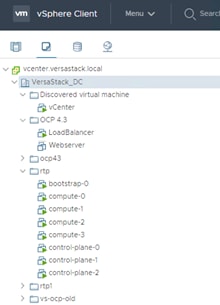
7. The bootstrap node is set up, which in turn will setup the cluster. The command succeeds when the Kubernetes API server signals that it has been bootstrapped on the control plane machines.
# cd <installation_directory>
# ./openshift-install --dir=. wait-for bootstrap-complete --log-level debug
DEBUG OpenShift Installer 4.3.18
DEBUG Built from commit db4411451af55e0bab7258d25bdabd91ea48382f
INFO Waiting up to 30m0s for the Kubernetes API at https://api.rtp.vs-ocp.com:6443...
DEBUG Still waiting for the Kubernetes API: Get https://api.rtp.vs-ocp.com:6443/version?timeout=32s:
DEBUG Still waiting for the Kubernetes API: Get https://api.rtp.vs-ocp.com:6443/version?timeout=32s: EOF
INFO API v1.16.2 up
INFO Waiting up to 30m0s for bootstrapping to complete...
DEBUG Bootstrap status: complete
INFO It is now safe to remove the bootstrap resources
More details about the installers progress can be viewed by looking at the “.install.openshift_install.log” in the installation directory using tail -f command
# tail -f .openshift_install.log
After bootstrap process is complete, remove the bootstrap machine from the load balancer by commenting or removing the entries from /etc/haproxy/haproxy.cfg and restart the HAproxy service.
8. We can remove the bootstrap node using Terraform as follows:
# cd /<tf-scripts>/openshift43-installer/
# terraform apply -auto-approve -var 'bootstrap_complete=true'
Logging into the Cluster
You can login to the cluster as a default system user by exporting the cluster kubeconfig file. The kubeconfig file contains information about the cluster that is used by the CLI to connect a client to the correct cluster and API server. The file is specific to a cluster and is created during OpenShift Container Platform installation.
To login to your newly created cluster, follow these steps:
Export the kubeadmin credentials, for <installation_directory>, specify the path to the directory that you stored the installation files in (ex:ocp43 in our case):
# export KUBECONFIG=<installation_directory>/auth/kubeconfig
EX: # export KUBECONFIG=~/ocp43/auth/kubeconfig
9. Verify you can run oc commands successfully using the exported configuration:
# oc whoami
system:admin
Approving the CSRs for Your Machines (Optional)
When machines are added to a cluster, two pending certificates signing request (CSRs) are generated for each machine that you added. You must confirm that these CSRs are approved or, if necessary, approve them yourself.
To approve the CSRs for your machines, follow these steps:
1. Review the pending certificate signing requests (CSRs) and ensure that the you see a client and server request with Pending or Approved status for each machine that you added to the cluster:
# oc get csr
NAME AGE REQUESTOR CONDITION
csr-2djmf 22m system:node:control-plane-2 Approved,Issued
csr-5q7nr 22m system:serviceaccount:openshift-machine-config-operator:node-bootstrapper Approved,Issued
csr-7lfnw 22m system:serviceaccount:openshift-machine-config-operator:node-bootstrapper Approved,Issued
csr-b5kd5 22m system:node:compute-0 Approved,Issued
csr-bfzkh 21m system:node:compute-3 Approved,Issued
csr-dq5kx 22m system:serviceaccount:openshift-machine-config-operator:node-bootstrapper Approved,Issued
csr-gn252 22m system:serviceaccount:openshift-machine-config-operator:node-bootstrapper Approved,Issued
csr-kr9fj 22m system:serviceaccount:openshift-machine-config-operator:node-bootstrapper Approved,Issued
csr-mtdmf 22m system:node:control-plane-0 Approved,Issued
csr-qbstz 22m system:node:compute-2 Approved,Issued
csr-qmj4c 22m system:serviceaccount:openshift-machine-config-operator:node-bootstrapper Approved,Issued
csr-sn5bs 22m system:node:control-plane-1 Approved,Issued
csr-tx8kv 22m system:node:compute-1 Approved,Issued
csr-zcxv7 22m system:serviceaccount:openshift-machine-config-operator:node-bootstrapper Approved,Issued
2. If the CSRs were not approved, after all of the pending CSRs for the machines you added are in Pending status, approve the CSRs for your cluster machines:
![]() Since the CSRs rotate automatically, approve the CSRs within an hour of adding the machines to the cluster. If you do not approve them within an hour, the certificates will rotate, and more than two certificates will be present for each node. You must approve all of these certificates. After you approve the initial CSRs, the subsequent node client CSRs are automatically approved by the cluster kube-controller-manager. You must implement a method of automatically approving the kubelet serving certificate requests
Since the CSRs rotate automatically, approve the CSRs within an hour of adding the machines to the cluster. If you do not approve them within an hour, the certificates will rotate, and more than two certificates will be present for each node. You must approve all of these certificates. After you approve the initial CSRs, the subsequent node client CSRs are automatically approved by the cluster kube-controller-manager. You must implement a method of automatically approving the kubelet serving certificate requests
3. To approve them individually, run the following command for each valid CSR:
#oc adm certificate approve <csr_name>
<csr_name> is the name of a CSR from the list of current CSRs.
4. To approve all pending CSRs, run the following command:
# oc get csr -o go-template='{{range .items}}{{if not .status}}{{.metadata.name}}{{"\n"}}{{end}}{{end}}' | xargs oc adm certificate approve
Configuring Cluster Operators
After the control plane initializes, immediately configure some Operators so that they all become available. To configure cluster operators, follow these steps:
1. Watch for the cluster operators to come online:
[root@192 install]# oc get co
NAME VERSION AVAILABLE PROGRESSING DEGRADED SINCE
authentication 4.3.18 True False False 5m39s
cloud-credential 4.3.18 True False False 23m
cluster-autoscaler 4.3.18 True False False 10m
console 4.3.18 True False False 7m16s
dns 4.3.18 True False False 18m
image-registry 4.3.18 True False False 11m
ingress 4.3.18 True False False 11m
insights 4.3.18 True False False 11m
kube-apiserver 4.3.18 True False False 13m
kube-controller-manager 4.3.18 True False False 13m
kube-scheduler 4.3.18 True False False 13m
machine-api 4.3.18 True False False 18m
machine-config 4.3.18 True False False 12m
marketplace 4.3.18 True False False 10m
monitoring 4.3.18 True False False 5m2s
network 4.3.18 True False False 19m
node-tuning 4.3.18 True False False 5m22s
openshift-apiserver 4.3.18 True False False 12m
openshift-controller-manager 4.3.18 True False False 13m
openshift-samples 4.3.18 True False False 10m
operator-lifecycle-manager 4.3.18 True False False 11m
operator-lifecycle-manager-catalog 4.3.18 True False False 11m
operator-lifecycle-manager-packageserver 4.3.18 True False False 10m
service-ca 4.3.18 True False False 18m
service-catalog-apiserver 4.3.18 True False False 11m
service-catalog-controller-manager 4.3.18 True False False 11m
storage 4.3.18 True False False 11m
2. Check the status of the cluster nodes:
#oc get nodes
NAME STATUS ROLES AGE VERSION
compute-0 Ready worker 21m v1.16.2
compute-1 Ready worker 21m v1.16.2
compute-2 Ready worker 21m v1.16.2
compute-3 Ready worker 21m v1.16.2
control-plane-0 Ready master 21m v1.16.2
control-plane-1 Ready master 21m v1.16.2
control-plane-2 Ready master 21m v1.16.2
3. The cluster creation process continues with the creation of many OpenShift operators:
[root@192 install]# ./openshift-install --dir=. wait-for install-complete
INFO Waiting up to 30m0s for the cluster at https://api.rtp.vs-ocp.com:6443 to initialize...
INFO Waiting up to 10m0s for the openshift-console route to be created...
INFO Install complete!
INFO To access the cluster as the system:admin user when using 'oc', run 'export KUBECONFIG=/root/ocp-rtp/install/auth/kubeconfig'
INFO Access the OpenShift web-console here: https://console-openshift-console.apps.rtp.vs-ocp.com
INFO Login to the console with user: kubeadmin, password: hUNDA-yWiL4-o8WSA-NG6mS
4. When the installation is completed, a message with access information will be displayed.
5. Point your browser to your web-console URL to login to OCP. Use kubeadmin for the username and displayed password.
6. The OCP Dashboard is loaded upon successful login.
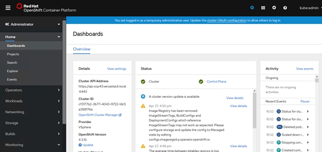
Setup Image Registry
For production deployments, a private image registry should be configured with persistent storage. The persistent storage must support ReadWriteMany access mode. This precludes the vSphere Storage Provider persistent storage as an option.
Extensions for private registries are acceptable within this architecture. For example, extensions to support image distribution, image auditing or CI/CD pipeline integration.
![]() The OpenShift Container Platform release 4.3 only supports NFS storage as the external persistent storage for private registry.
The OpenShift Container Platform release 4.3 only supports NFS storage as the external persistent storage for private registry.
The solution validation team implemented an emptyDir for image registry as documented in the following steps, images pushed to the image registry are not saved following a reboot.
For customer production deployments it is highly recommended to use an NFS share for image registry storage as the images stored in the registry will sustain reboots.
On platforms that do not provide shareable object storage, the OpenShift Image Registry Operator bootstraps itself as Removed. This allows openshift-installer to complete installations on these platform types.
To setup the image registry, follow these steps:
1. Verify the image registry operator is running in the openshift-image-registry namespace:
# oc get pods -n openshift-image-registry
NAME READY STATUS RESTARTS AGE
cluster-image-registry-operator-86476f46bc-p9kkx 2/2 Running 0 27m
2. Change ManagementState Image Registry Operator configuration from Removed to Managed.
# oc patch configs.imageregistry.operator.openshift.io cluster --type merge --patch '{"spec":{"managementState": "Managed"}}'
config.imageregistry.operator.openshift.io/cluster patched
![]() If you run this command before the Image Registry Operator initializes its components, the oc patch command fails with the following error:
If you run this command before the Image Registry Operator initializes its components, the oc patch command fails with the following error:
3. Set the image registry storage to an empty directory with below command:
# oc patch configs.imageregistry.operator.openshift.io cluster --type merge --patch '{"spec":{"storage":{"emptyDir":{}}}}'
config.imageregistry.operator.openshift.io/cluster patched
4. Verify the registry status as running:
# oc get pods -n openshift-image-registry
NAME READY STATUS RESTARTS AGE
cluster-image-registry-operator-86476f46bc-p9kkx 2/2 Running 0 31m
image-registry-76c48d9845-qs9nc 1/1 Running 0 23s
node-ca-7v2s4 1/1 Running 0 24s
node-ca-bhwhr 1/1 Running 0 24s
node-ca-dwclq 1/1 Running 0 24s
node-ca-jmcf5 1/1 Running 0 24s
node-ca-nqdgc 1/1 Running 0 24s
node-ca-p6vmq 1/1 Running 0 24s
node-ca-wrmwp 1/1 Running 0 24s
![]() If you want to configure NFS storage for image registry storage, please follow the official Red hat documentation for implementation procedure.
If you want to configure NFS storage for image registry storage, please follow the official Red hat documentation for implementation procedure.
Configure Authentication
By default, only a kubeadmin user exists on the cluster. To add users to the system, an identity provider needs to be specified, we must create a Custom Resource (CR) that describes that identity provider and add it to the cluster.
This section describes how to configure identity providers by using htpasswd.
For more information about supported authentication providers, see Understanding authentication in the OpenShift Container Platform documentation.
Creating an Admin User
To create an admin user, follow these steps:
1. Login to the management host.
Install httpd-tools if the management node does not have access to htpasswd
2. Create or update your flat file with a username and hashed password:
# htpasswd -c -B -b </path/to/users.htpasswd> <user_name> <password>
For Example:
# cd <install directory>/
# htpasswd -c -B -b htpasswd admin1 Password1
3. Continue to add or update credentials to the file to add additional users.
# htpasswd -B -b </path/to/users.htpasswd> <user_name> <password>
For Example:
# htpasswd -B -b htpasswd ocpuser1 Password2
4. Create a secret for htpasswd:
# oc create secret generic htpass-secret --from-file=htpasswd=/home/core/openshift/htpasswd -n openshift-config
5. To use the HTPasswd identity provider, a secret must be defined that contains the HTPasswd user file.
6. Create an OpenShift Container Platform Secret that contains the HTPasswd users file. Create a yaml file with the following contents on the management host.
apiVersion: config.openshift.io/v1
kind: OAuth
metadata:
name: cluster
spec:
identityProviders:
- name: htpasswd
mappingMethod: claim
type: HTPasswd
htpasswd:
fileData:
name: htpass-secret
7. Apply the defined CR:
# oc apply -f <file name>
8. Log into the cluster as a user created with htpasswd.
# oc login -u <username>
Authentication required for https://api.rtp.vs-ocp.com:6443 (openshift)
Username: username
Password: password
Login successful.
Assigning a cluster-admin Role to a User
To assign a cluster-admin role to the admin user, follow these steps:
1. Log in as kubeadmin to assign cluster-admin access:
# oc login -u kubeadmin -p PASSWORD
Login successful.
You have access to 53 projects, the list has been suppressed. You can list all projects with 'oc projects'
Using project "default".
2. Run the following command and ensure that the user is listed:
# oc get users
NAME UID FULL NAME IDENTITIES
ocpadmin 273ccf25-9b32-4b4d-aad4-503c5aa27eee htpasswd:admin1
3. Get a list of all available cluster roles:
# oc get clusterrole --all-namespaces
4. Assign the cluster-admin role to the user <admin1> created earlier as follows:
# oc adm policy add-cluster-role-to-user cluster-admin admin1
clusterrole.rbac.authorization.k8s.io/cluster-admin added: "admin1"
5. To configure the identify providers using web console if you prefer:
a. Navigate to Administration > Cluster Settings.
b. Under the Global Configuration tab, click OAuth.
c. Under the Identity Providers section, select your identity provider from the Add drop-down list.
IBM CSI Driver Installation and Configuration
This section provides a set of instructions about installing and configuring IBM CSI driver for block storage in the Kubernetes cluster for OCP and creating storage classes and provisioning PVCs. IBM CSI version 1.1.0 is used in this reference, for the latest version and generic installation procedures of IBM CSI please refer to:
https://github.com/IBM/ibm-block-csi-driver
As mentioned in the solution design section of this document, IBM CSI is a dynamic storage provisioner for Kubernetes and it is completely integrated in the Kubernetes environment and run as a pod. IBM CSI is used to dynamically provision and delete storage services within the Kubernetes’ framework.
![]() Proper configuration of the IBM FlashSystem backend storage system is required prior to the actual installation of IBM CSI driver. These requirements are covered in the solution design section of this document.
Proper configuration of the IBM FlashSystem backend storage system is required prior to the actual installation of IBM CSI driver. These requirements are covered in the solution design section of this document.
Preparing the IBM FlashSystem Backend Storage
The IBM FlashSystem storage system has to be designed and configured in a way that it can provide the required services for the OCP-Kubernetes cluster. These requirements will be defined in collaboration between the users of the OCP platform and the storage team. The storage design aspects are covered in the solution design section of this document.
Red Hat OpenShift Container Platform 4.3 worker nodes must be configured to access the IBM storage system. This section describes how to configure the storage system with the Red Hat OpenShift Container Platform worker nodes.
The validation team performed the following steps in the solution lab environment to install and configure iSCSI on worker nodes:
Storage Pools Configuration
The following storage pool is defined to support dynamic storage provisioning for OCP, the storage capacity from this pool has been allocated for OCP solution storage configuration:
· VS-Pool1
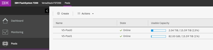
The following are the details of iSCSI configuration on IBM FlashSystem system to support OCP solution on VersaStack.
IBM SVC nodes iSCSI interface details:
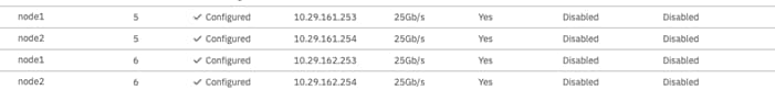
IBM SVC nodes iSCSI name (IQN) details:
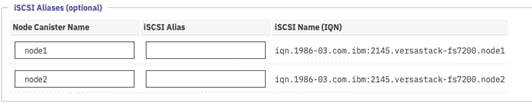
Configuring Worker Nodes Running Red Hat Enterprise Linux CoreOS
For OpenShift Container Platform, RHCOS images are set up initially with a feature called Ignition, which runs only on the system’s first boot. After first boot, RHCOS systems are managed by the Machine Config Operator (MCO) that runs in the OpenShift Container Platform cluster.
In this section, MachineConfig is created to add two additional network interfaces on each worker node and to deploy /etc/multipath.conf and /etc/udev/rules.d to support iSCSI connections to IBM Storage systems. In addition, iSCSI connectivity can be configured, as needed.
Add New Network Adapters to the Worker Nodes for iSCSI Access
To add new network adapters to the worker nodes for iSCSI access, follow these steps on each worker node:
1. Access VersaStack vCenter.
2. Right-click a worker node in the inventory and select Edit Settings.
3. Click ADD NEW DEVICE.
4. Select Network Adapter from the drop-down list
The new network adapter appears at the bottom of the device list.
Expand New Network and check the boxes against both Connected and Connected at power on.
From the drop-down list next to the New Network label, select the iSCSI-A port group.
5. Click OK.
6. Click ADD NEW DEVICE again.
7. Select Network Adapter from the drop-down list
8. The new network adapter appears at the bottom of the device list.
9. Expand New Network and check the boxes against Connected and Connected at power on.
From the drop-down list next to the New Network label, select the iSCSI-B port group.
10. Repeat the above steps for all the worker nodes.
11. Note down the MAC addresses of the newly created adapters on all the worker nodes. The MAC addresses will be used to assign IP addresses from storage VLAN to the adapters using machine config file.
The new network adapters will be configured through defining new machineconfig resources as follows.
Create a new ifcfg text file which defines a HWADDR which corresponds to the MAC address of the adapter to be configured. Create one file for each adapter on all worker nodes.
HWADDR=00:50:56:98:9f:ee
TYPE=Ethernet
BOOTPROTO=none
IPADDR=10.29.162.201
PREFIX=24
DNS1=10.1.162.2
ONBOOT=yes
GATEWAY=10.29.162.1
Run the following command to base64 encode the ifcfg file(s).
# cat ifcfg-file | base64 -w 0
SFdBRERSPTAwOjUwOjU2Ojk4OjlmOmVlClRZUEU9RXRoZXJuZXQKQk9PVFBST1RPPW5vbmUKSVBBRERSPTEwLjI5LjE2Mi4yMDEKUFJFRklYPTI0CkROUzE9MTAuMS4xNjIuMgpPTkJPT1Q9eWVzCkdBVEVXQVk9MTAuMjkuMTYyLjEK
Create a new machineconfig yaml file which contains the base64 encoded ifcfg files.
Append the base64 content after data:text/plain;charset=utf-8;base64,
Below is an example to configure two network adapters (iSCSI-A and iSCSI-B paths) on each worker node in a cluster consisting of four worker nodes. A file was created with the name the-machine-config and the contents were updated as follows:
{
"apiVersion": "machineconfiguration.openshift.io/v1",
"kind": "MachineConfig",
"metadata": {
"labels": {
"machineconfiguration.openshift.io/role": "worker"
},
"name": "99-storage-network"
},
"spec": {
"config":
{
"ignition": {
"config": {},
"timeouts": {},
"version": "2.1.0"
},
"networkd": {},
"passwd": {},
"storage": {
"files": [
{
"filesystem": "root",
"path": "/etc/sysconfig/network-scripts/ifcfg-compute-01-sn",
"contents": {
"source": "data:text/plain;charset=utf-8;base64,SFdBRERSPTAwOjUwOjU2Ojk4OjE4OmRkClRZUEU9RXRoZXJuZXQKQk9PVFBST1RPPW5vbmUKSVBBRERSPTEwLjI5LjE2MS4yMDEKUFJFRklYPTI0CkROUzE9MTAuMS4xNjIuMgpPTkJPT1Q9eWVzCkdBVEVXQVk9MTAuMjkuMTYxLjEK",
"verification": {}
},
"mode": 420
},
{
"filesystem": "root",
"path": "/etc/sysconfig/network-scripts/ifcfg-compute-02-sn",
"contents": {
"source": "data:text/plain;charset=utf-8;base64,SFdBRERSPTAwOjUwOjU2Ojk4OjY3OmUzClRZUEU9RXRoZXJuZXQKQk9PVFBST1RPPW5vbmUKSVBBRERSPTEwLjI5LjE2Mi4yMDEKUFJFRklYPTI0CkROUzE9MTAuMS4xNjIuMgpPTkJPT1Q9eWVzCkdBVEVXQVk9MTAuMjkuMTYyLjEK",
"verification": {}
},
"mode": 420
},
{
"filesystem": "root",
"path": "/etc/sysconfig/network-scripts/ifcfg-compute-11-sn",
"contents": {
"source": "data:text/plain;charset=utf-8;base64,SFdBRERSPTAwOjUwOjU2Ojk4OmNhOmYxClRZUEU9RXRoZXJuZXQKQk9PVFBST1RPPW5vbmUKSVBBRERSPTEwLjI5LjE2MS4yMDIKUFJFRklYPTI0CkROUzE9MTAuMS4xNjIuMgpPTkJPT1Q9eWVzCkdBVEVXQVk9MTAuMjkuMTYxLjEK",
"verification": {}
},
"mode": 420
},
{
"filesystem": "root",
"path": "/etc/sysconfig/network-scripts/ifcfg-compute-12-sn",
"contents": {
"source": "data:text/plain;charset=utf-8;base64,SFdBRERSPTAwOjUwOjU2Ojk4OmZjOjJkClRZUEU9RXRoZXJuZXQKQk9PVFBST1RPPW5vbmUKSVBBRERSPTEwLjI5LjE2Mi4yMDIKUFJFRklYPTI0CkROUzE9MTAuMS4xNjIuMgpPTkJPT1Q9eWVzCkdBVEVXQVk9MTAuMjkuMTYyLjEK",
"verification": {}
},
"mode": 420
},
{
"filesystem": "root",
"path": "/etc/sysconfig/network-scripts/ifcfg-compute-21-sn",
"contents": {
"source": "data:text/plain;charset=utf-8;base64,SFdBRERSPTAwOjUwOjU2Ojk4OmY1OjhlClRZUEU9RXRoZXJuZXQKQk9PVFBST1RPPW5vbmUKSVBBRERSPTEwLjI5LjE2MS4yMDMKUFJFRklYPTI0CkROUzE9MTAuMS4xNjIuMgpPTkJPT1Q9eWVzCkdBVEVXQVk9MTAuMjkuMTYxLjEK",
"verification": {}
},
"mode": 420
},
{
"filesystem": "root",
"path": "/etc/sysconfig/network-scripts/ifcfg-compute-22-sn",
"contents": {
"source": "data:text/plain;charset=utf-8;base64,SFdBRERSPTAwOjUwOjU2Ojk4OjkwOjVkClRZUEU9RXRoZXJuZXQKQk9PVFBST1RPPW5vbmUKSVBBRERSPTEwLjI5LjE2Mi4yMDMKUFJFRklYPTI0CkROUzE9MTAuMS4xNjIuMgpPTkJPT1Q9eWVzCkdBVEVXQVk9MTAuMjkuMTYyLjEK",
"verification": {}
},
"mode": 420
},
{
"filesystem": "root",
"path": "/etc/sysconfig/network-scripts/ifcfg-compute-31-sn",
"contents": {
"source": "data:text/plain;charset=utf-8;base64,SFdBRERSPTAwOjUwOjU2Ojk4OmQ4OmU1ClRZUEU9RXRoZXJuZXQKQk9PVFBST1RPPW5vbmUKSVBBRERSPTEwLjI5LjE2MS4yMDQKUFJFRklYPTI0CkROUzE9MTAuMS4xNjIuMgpPTkJPT1Q9eWVzCkdBVEVXQVk9MTAuMjkuMTYxLjEK",
"verification": {}
},
"mode": 420
},
{
"filesystem": "root",
"path": "/etc/sysconfig/network-scripts/ifcfg-compute-32-sn",
"contents": {
"source": "data:text/plain;charset=utf-8;base64,SFdBRERSPTAwOjUwOjU2Ojk4OjgyOjY2ClRZUEU9RXRoZXJuZXQKQk9PVFBST1RPPW5vbmUKSVBBRERSPTEwLjI5LjE2Mi4yMDQKUFJFRklYPTI0CkROUzE9MTAuMS4xNjIuMgpPTkJPT1Q9eWVzCkdBVEVXQVk9MTAuMjkuMTYyLjEK",
"verification": {}
},
"mode": 420
}
]
},
"systemd": {}
},
"osImageURL": ""
}
}
Apply the machineconfig by running the following command
# oc apply -f the-machine-config
machineconfig.machineconfiguration.openshift.io/99-storage-network created
12. Wait for all impacted nodes to restart.
Configure OpenShift Container Platform with Multipathing
To configure storage multipathing for IBM FlashSystem storage arrays on the OpenShift Container Platform worker nodes, follow these steps:
For this process a file 99-ibm-attach.yaml is used to apply the configuration on the worker nodes via machine config operator.
The 99-ibm-attach.yaml configuration file overrides any multipath.conf file that already exists on your system. Only use this file if one is not already created!
Wait for all impacted nodes to restart. Create a new file <99-ibm-attach.yaml> on the management node and copy the contents from below into the file and save the file.
# cat 99-fc-attach.yaml
apiVersion: machineconfiguration.openshift.io/v1
kind: MachineConfig
metadata:
labels:
machineconfiguration.openshift.io/role: worker
name: 99-ibm-attach
spec:
config:
ignition:
version: 2.2.0
storage:
files:
- path: /etc/multipath.conf
mode: 384
filesystem: root
contents:
source: data:,defaults%20%7B%0A%20%20%20%20path_checker%20tur%0A%20%20%20%20path_selector%20%22round-robin%200%22%0A%20%20%20%20rr_weight%20uniform%0A%20%20%20%20prio%20const%0A%20%20%20%20rr_min_io_rq%201%20%20%20%20%20%20%20%20%20%20%20%20%20%20%20%0A%20%20%20%20polling_interval%2030%0A%20%20%20%20path_grouping_policy%20multibus%0A%20%20%20%20find_multipaths%20yes%0A%20%20%20%20no_path_retry%20fail%0A%20%20%20%20user_friendly_names%20yes%0A%20%20%20%20failback%20immediate%0A%20%20%20%20checker_timeout%2010%0A%20%20%20%20fast_io_fail_tmo%20off%0A%7D%0A%0Adevices%20%7B%0A%20%20%20%20device%20%7B%0A%20%20%20%20%20%20%20%20path_checker%20tur%0A%20%20%20%20%20%20%20%20product%20%22FlashSystem%22%0A%20%20%20%20%20%20%20%20vendor%20%22IBM%22%0A%20%20%20%20%20%20%20%20rr_weight%20uniform%0A%20%20%20%20%20%20%20%20rr_min_io_rq%204%20%20%20%20%20%20%20%20%20%20%20%20%20%20%20%0A%20%20%20%20%20%20%20%20path_grouping_policy%20multibus%0A%20%20%20%20%20%20%20%20path_selector%20%22round-robin%200%22%0A%20%20%20%20%20%20%20%20no_path_retry%20fail%0A%20%20%20%20%20%20%20%20failback%20immediate%0A%20%20%20%20%7D%0A%20%20%20%20device%20%7B%0A%20%20%20%20%20%20%20%20path_checker%20tur%0A%20%20%20%20%20%20%20%20product%20%22FlashSystem-9840%22%0A%20%20%20%20%20%20%20%20vendor%20%22IBM%22%0A%20%20%20%20%20%20%20%20fast_io_fail_tmo%20off%0A%20%20%20%20%20%20%20%20rr_weight%20uniform%0A%20%20%20%20%20%20%20%20rr_min_io_rq%201000%20%20%20%20%20%20%20%20%20%20%20%20%0A%20%20%20%20%20%20%20%20path_grouping_policy%20multibus%0A%20%20%20%20%20%20%20%20path_selector%20%22round-robin%200%22%0A%20%20%20%20%20%20%20%20no_path_retry%20fail%0A%20%20%20%20%20%20%20%20failback%20immediate%0A%20%20%20%20%7D%0A%20%20%20%20device%20%7B%0A%20%20%20%20%20%20%20%20vendor%20%22IBM%22%0A%20%20%20%20%20%20%20%20product%20%222145%22%0A%20%20%20%20%20%20%20%20path_checker%20tur%0A%20%20%20%20%20%20%20%20features%20%221%20queue_if_no_path%22%0A%20%20%20%20%20%20%20%20path_grouping_policy%20group_by_prio%0A%20%20%20%20%20%20%20%20path_selector%20%22service-time%200%22%20%23%20Used%20by%20Red%20Hat%207.x%0A%20%20%20%20%20%20%20%20prio%20alua%0A%20%20%20%20%20%20%20%20rr_min_io_rq%201%0A%20%20%20%20%20%20%20%20no_path_retry%20%225%22%0A%20%20%20%20%20%20%20%20dev_loss_tmo%20120%0A%20%20%20%20%20%20%20%20failback%20immediate%0A%20%20%20%7D%0A%7D%0A
verification: {}
- path: /etc/udev/rules.d/99-ibm-2145.rules
mode: 420
filesystem: root
contents:
source: data:,%23%20Set%20SCSI%20command%20timeout%20to%20120s%20%28default%20%3D%3D%2030%20or%2060%29%20for%20IBM%202145%20devices%0ASUBSYSTEM%3D%3D%22block%22%2C%20ACTION%3D%3D%22add%22%2C%20ENV%7BID_VENDOR%7D%3D%3D%22IBM%22%2CENV%7BID_MODEL%7D%3D%3D%222145%22%2C%20RUN%2B%3D%22/bin/sh%20-c%20%27echo%20120%20%3E/sys/block/%25k/device/timeout%27%22%0A
verification: {}
systemd:
units:
- name: multipathd.service
enabled: true
#- name: iscsid.service
# enabled: true
13. Apply the yaml file using the following command:
# oc apply -f 99-fc-attach.yaml
machineconfig.machineconfiguration.openshift.io/99-ibm-attach created
14. Login to each worker node (ssh as core user) and verify the status of multipathing and make sure there are no errors:
# systemctl status multipathd
iSCSI Connectivity Configuration
To configure iSCSI connectivity, follow these steps on each worker node:
1. SSH to each worker node with the core user and verify the iSCSI initiator name to be used for host mappings on the IBM Storwize.
InitiatorName=iqn.1994-05.com.Red Hat:<hostname>-<random generated number>
[core@compute-0 ~]# sudo cat /etc/iscsi/initiatorname.iscsi
InitiatorName=iqn.1994-05.com.RedHat:8d2724793412
Add host definitions to the IBM FlashSystem storage array by selecting hosts from the management GUI console. Also, provide the iSCSI initiator name shown in the previous step 1 in the /etc/iscsi/initiatorname.iscsi file
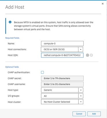
2. Discover the iSCSI targets by using the iscsiadm CLI:
![]() The iSCSI commands for discovery and login are not required and are only included here as a reference for the user to test the connectivity.
The iSCSI commands for discovery and login are not required and are only included here as a reference for the user to test the connectivity.
iscsiadm -m discoverydb -t st -p <IP Address configured for iSCSI @ FlashSystem Storage Array>:3260 --discover
#sudo iscsiadm -m discoverydb -t st -p 10.29.161.253:3260 --discover
#sudo iscsiadm -m discoverydb -t st -p 10.29.161.254:3260 --discover
#sudo iscsiadm -m discoverydb -t st -p 10.29.162.253:3260 --discover
#sudo iscsiadm -m discoverydb -t st -p 10.29.162.254:3260 –-discover
The output should be as follows:
[core@compute-3 ~]# sudo iscsiadm -m discoverydb -t st -p 10.29.161.254:3260 --discover
10.29.161.254:3260,1 iqn.1986-03.com.ibm:2145.versastack-fs7200.node2
10.29.162.254:3260,1 iqn.1986-03.com.ibm:2145.versastack-fs7200.node2
[core@compute-3 ~]# sudo iscsiadm -m discoverydb -t st -p 10.29.162.253:3260 --discover
10.29.161.253:3260,1 iqn.1986-03.com.ibm:2145.versastack-fs7200.node1
10.29.162.253:3260,1 iqn.1986-03.com.ibm:2145.versastack-fs7200.node1
[core@compute-3 ~]# sudo iscsiadm -m discoverydb -t st -p 10.29.162.254:3260 --discover
10.29.161.254:3260,1 iqn.1986-03.com.ibm:2145.versastack-fs7200.node2
10.29.162.254:3260,1 iqn.1986-03.com.ibm:2145.versastack-fs7200.node2
[core@compute-3 ~]# sudo iscsiadm -m discoverydb -t st -p 10.29.161.253:3260 --discover
10.29.161.253:3260,1 iqn.1986-03.com.ibm:2145.versastack-fs7200.node1
10.29.162.253:3260,1 iqn.1986-03.com.ibm:2145.versastack-fs7200.node1
# BEGIN RECORD 6.2.0.877-0
discovery.startup = manual
discovery.type = sendtargets
discovery.sendtargets.address = 10.29.162.254
discovery.sendtargets.port = 3260
discovery.sendtargets.auth.authmethod = None
discovery.sendtargets.auth.username = <empty>
discovery.sendtargets.auth.password = <empty>
discovery.sendtargets.auth.username_in = <empty>
discovery.sendtargets.auth.password_in = <empty>
discovery.sendtargets.timeo.login_timeout = 15
discovery.sendtargets.use_discoveryd = No
discovery.sendtargets.discoveryd_poll_inval = 30
discovery.sendtargets.reopen_max = 5
discovery.sendtargets.timeo.auth_timeout = 45
discovery.sendtargets.timeo.active_timeout = 30
discovery.sendtargets.iscsi.MaxRecvDataSegmentLength = 32768
# END RECORD
Log in to iSCSI targets using the iscsiadm CLI tool:
iscsiadm -m node -p <IP Address configured for iSCSI @ FlashSystem Storage Array>:3260 --login
# sudo iscsiadm -m node -p 10.29.161.253:3260 --login
# sudo iscsiadm -m node -p 10.29.161.254:3260 --login
# sudo iscsiadm -m node -p 10.29.162.253:3260 --login
# sudo iscsiadm -m node -p 10.29.162.254:3260 –-login
The output for the above commands should be as follows:
[core@compute-1 ~]# sudo iscsiadm -m node -p 10.29.161.253:3260 --login
Logging in to [iface: default, target: iqn.1986-03.com.ibm:2145.versastack-fs7200.node1, portal: 10.29.161.253,3260]
Login to [iface: default, target: iqn.1986-03.com.ibm:2145.versastack-fs7200.node1, portal: 10.29.161.253,3260] successful.
[core@compute-1 ~]# sudo iscsiadm -m node -p 10.29.161.254:3260 --login
Logging in to [iface: default, target: iqn.1986-03.com.ibm:2145.versastack-fs7200.node2, portal: 10.29.161.254,3260]
Login to [iface: default, target: iqn.1986-03.com.ibm:2145.versastack-fs7200.node2, portal: 10.29.161.254,3260] successful.
[core@compute-1 ~]# sudo iscsiadm -m node -p 10.29.162.253:3260 --login
Logging in to [iface: default, target: iqn.1986-03.com.ibm:2145.versastack-fs7200.node1, portal: 10.29.162.253,3260]
Login to [iface: default, target: iqn.1986-03.com.ibm:2145.versastack-fs7200.node1, portal: 10.29.162.253,3260] successful.
[core@compute-1 ~]# sudo iscsiadm -m node -p 10.29.162.254:3260 --login
Logging in to [iface: default, target: iqn.1986-03.com.ibm:2145.versastack-fs7200.node2, portal: 10.29.162.254,3260]
Login to [iface: default, target: iqn.1986-03.com.ibm:2145.versastack-fs7200.node2, portal: 10.29.162.254,3260] successful.
# BEGIN RECORD 2.0-877
node.name = iqn.1986-03.com.ibm:2145.versastack-fs7200.node2
node.tpgt = 1
node.startup = automatic
node.leading_login = No
iface.iscsi_ifacename = default
iface.net_ifacename = <empty>
iface.ipaddress = <empty>
iface.prefix_len = 0
iface.hwaddress = <empty>
iface.transport_name = tcp
iface.initiatorname = <empty>
iface.state = <empty>
iface.vlan_id = 0
iface.vlan_priority = 0
iface.vlan_state = <empty>
iface.iface_num = 0
iface.mtu = 0
iface.port = 0
iface.bootproto = <empty>
iface.subnet_mask = <empty>
iface.gateway = <empty>
iface.dhcp_alt_client_id_state = <empty>
iface.dhcp_alt_client_id = <empty>
iface.dhcp_dns = <empty>
iface.dhcp_learn_iqn = <empty>
iface.dhcp_req_vendor_id_state = <empty>
iface.dhcp_vendor_id_state = <empty>
iface.dhcp_vendor_id = <empty>
iface.dhcp_slp_da = <empty>
iface.fragmentation = <empty>
iface.gratuitous_arp = <empty>
iface.incoming_forwarding = <empty>
iface.tos_state = <empty>
iface.tos = 0
iface.ttl = 0
iface.delayed_ack = <empty>
iface.tcp_nagle = <empty>
iface.tcp_wsf_state = <empty>
iface.tcp_wsf = 0
iface.tcp_timer_scale = 0
iface.tcp_timestamp = <empty>
iface.redirect = <empty>
iface.def_task_mgmt_timeout = 0
iface.header_digest = <empty>
iface.data_digest = <empty>
iface.immediate_data = <empty>
iface.initial_r2t = <empty>
iface.data_seq_inorder = <empty>
iface.data_pdu_inorder = <empty>
iface.erl = 0
iface.max_receive_data_len = 0
iface.first_burst_len = 0
iface.max_outstanding_r2t = 0
iface.max_burst_len = 0
iface.chap_auth = <empty>
iface.bidi_chap = <empty>
iface.strict_login_compliance = <empty>
iface.discovery_auth = <empty>
iface.discovery_logout = <empty>
node.discovery_address = 10.29.162.254
node.discovery_port = 3260
node.discovery_type = send_targets
node.session.initial_cmdsn = 0
node.session.initial_login_retry_max = 8
node.session.xmit_thread_priority = -20
node.session.cmds_max = 128
node.session.queue_depth = 32
node.session.nr_sessions = 1
node.session.auth.authmethod = None
node.session.auth.username = <empty>
node.session.auth.password = <empty>
node.session.auth.username_in = <empty>
node.session.auth.password_in = <empty>
node.session.timeo.replacement_timeout = 120
node.session.err_timeo.abort_timeout = 15
node.session.err_timeo.lu_reset_timeout = 30
node.session.err_timeo.tgt_reset_timeout = 30
node.session.err_timeo.host_reset_timeout = 60
node.session.iscsi.FastAbort = Yes
node.session.iscsi.InitialR2T = No
node.session.iscsi.ImmediateData = Yes
node.session.iscsi.FirstBurstLength = 262144
node.session.iscsi.MaxBurstLength = 16776192
node.session.iscsi.DefaultTime2Retain = 0
node.session.iscsi.DefaultTime2Wait = 2
node.session.iscsi.MaxConnections = 1
node.session.iscsi.MaxOutstandingR2T = 1
node.session.iscsi.ERL = 0
node.session.scan = auto
node.session.reopen_max = 0
node.conn[0].address = 10.29.162.254
node.conn[0].port = 3260
node.conn[0].startup = manual
node.conn[0].tcp.window_size = 524288
node.conn[0].tcp.type_of_service = 0
node.conn[0].timeo.logout_timeout = 15
node.conn[0].timeo.login_timeout = 15
node.conn[0].timeo.auth_timeout = 45
node.conn[0].timeo.noop_out_interval = 5
node.conn[0].timeo.noop_out_timeout = 5
node.conn[0].iscsi.MaxXmitDataSegmentLength = 0
node.conn[0].iscsi.MaxRecvDataSegmentLength = 262144
node.conn[0].iscsi.HeaderDigest = None
node.conn[0].iscsi.DataDigest = None
node.conn[0].iscsi.IFMarker = No
node.conn[0].iscsi.OFMarker = No
# END RECORD
3. Verify the host using the FlashSystem GUI console, make sure the status becomes online from being previously offline.
![]() Hosts might become online after a volume is presented and might be in degraded stage until then.
Hosts might become online after a volume is presented and might be in degraded stage until then.
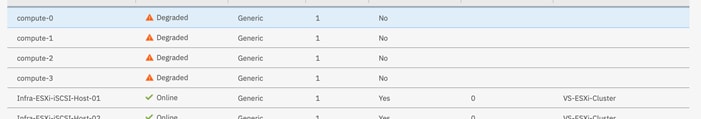
Install IBM Block Storage CSI Driver on Red Hat OpenShift Container Platform
The following section describes how to install the IBM block storage CSI driver to work with OpenShift Container Platform 4.3. The source code and additional information can be found on Github at https://github.com/IBM/ibm-block-csi-driver/.
Installing from the OpenShift Web Console
When using the Red Hat OpenShift Container Platform, the Operator for IBM block storage CSI driver can be installed directly from the OpenShift web console, through the OperatorHub. Installing the CSI (Container Storage Interface) driver is part of the Operator installation process. The source code and additional information can be found on Github:
https://github.com/IBM/ibm-block-csi-driver/
https://github.com/IBM/ibm-block-csi-operator
To install the driver, follow these steps:
From Red Hat OpenShift Container Platform Operators > OperatorHub, select Project: kube-system.
4. Search for IBM block storage CSI driver, as shown below:
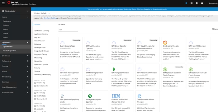
5. Select the Operator for IBM block storage CSI driver and click Install. The Operator Subscription form displays.
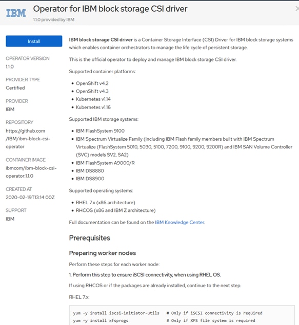
Set the Installation Mode to kube-system, under A specific namespace on the cluster.
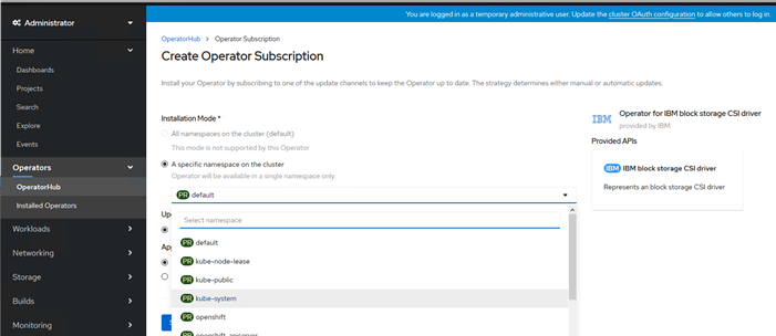
6. Click Subscribe.
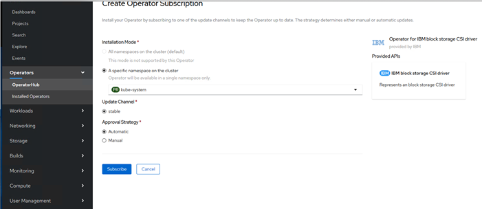
7. Go to Operators > Installed Operators; check the status of the Operator for IBM block storage CSI driver. Wait until the Status is up-to-date and then the status will change to Install Succeeded.
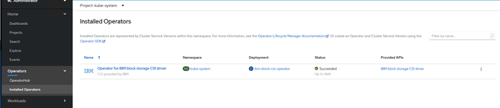
8. While waiting for the Status to change from up-to-date to Install Succeeded, you can check the pod progress and readiness status from Workloads > Pods.
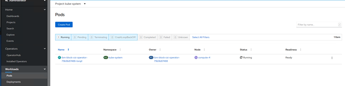
9. When the operator installation progress has completed, click the installed Operator for IBM block storage CSI driver.
Click Create Instance to create IBMBlocks CSI.
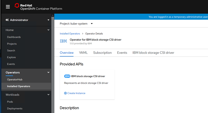
10. Edit the yaml file in the web console as follows, if needed only.
apiVersion: csi.ibm.com/v1
kind: IBMBlockCSI
metadata:
name: ibm-block-csi
namespace: kube-system
spec:
controller:
repository: ibmcom/ibm-block-csi-driver-controller
tag: 1.1.0
imagePullPolicy: IfNotPresent
affinity:
nodeAffinity:
requiredDuringSchedulingIgnoredDuringExecution:
nodeSelectorTerms:
- matchExpressions:
- key: kubernetes.io/arch
operator: In
values:
- amd64
- s390x
node:
repository: ibmcom/ibm-block-csi-driver-node
tag: 1.1.0
imagePullPolicy: IfNotPresent
affinity:
nodeAffinity:
requiredDuringSchedulingIgnoredDuringExecution:
nodeSelectorTerms:
- matchExpressions:
- key: kubernetes.io/arch
operator: In
values:
- amd64
- s390x
sidecars:
- name: csi-node-driver-registrar
repository: registry.Red Hat.io/openshift4/ose-csi-driver-registrar
tag: latest
imagePullPolicy: IfNotPresent
- name: csi-provisioner
repository: registry.Red Hat.io/openshift4/ose-csi-external-provisioner-rhel7
tag: latest
imagePullPolicy: IfNotPresent
- name: csi-attacher
repository: registry.Red Hat.io/openshift4/ose-csi-external-attacher
tag: latest
imagePullPolicy: IfNotPresent
- name: livenessprobe
repository: registry.Red Hat.io/openshift4/ose-csi-livenessprobe
tag: latest
imagePullPolicy: IfNotPresent
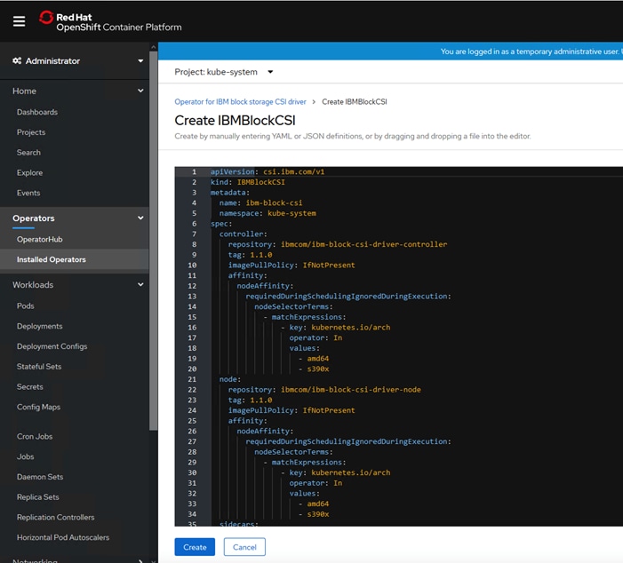
Click Create and Wait until the Status is Running.
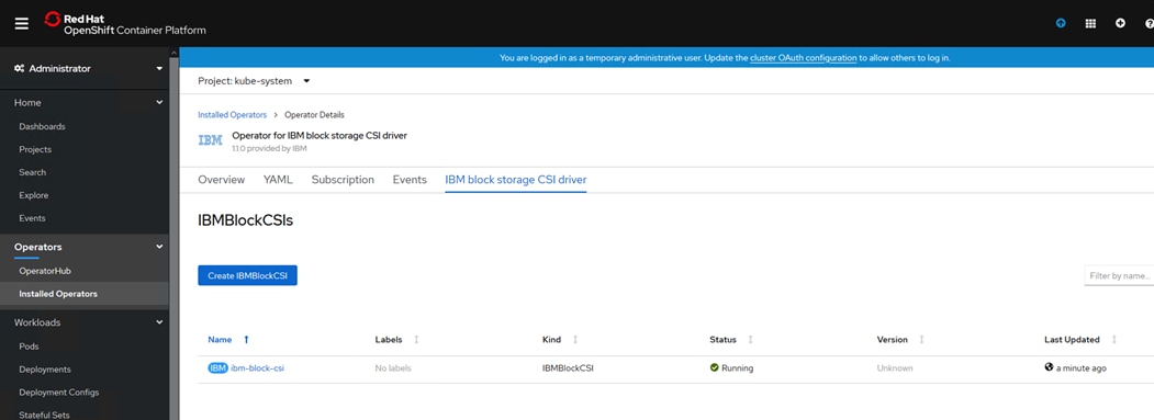
Create a Secret for Authentication to IBM FlashSystem
There are two ways to create a secret so that the OpenShift CSI driver communicates with an IBM FlashSystem storage for initiating storage provisioning and management for containers:
Option 1: Create a storage device secret from a YAML file
The data value for password needs to be encoded as base64 for entry in to the yaml file. The output from base64 will be entered in the data.Password field.
# echo <superuser-passwd> | base64
c3VwZXJ1c2VyLXBhc3N3ZAo=
# cat storwize-secret.yml
apiVersion: v1
kind: Secret
metadata:
name: storwize
namespace: kube-system labels:
product: ibm-block-csi-driver
type: Opaque
stringData:
# Array username.
username: superuser
# Array managment addresses
management_address: 192.168.162.14
data:
# Base64-encoded password to authenticate with the storage system.
password: "c3VwZXJ1c2VyLXBhc3N3ZAo="
Option 2: Create a secret with the oc command line
1. Run the following command from management host to create the secret, Option 2 was selected to create a secret during validation exercise:
# oc create secret generic storwize --from-literal=management_address=<192.168.162.14> --from-literal=username=superuser --from-literal=password=<passw0rd> -n kube-system
secret/storwize created
Create a block.csi.ibm.com StorageClass
To create a Storage Class (additional storage classes can be defined using the (YAML) configuration files if needed) follow these steps. These storage classes can be used for persistent volume creation during the application containers deployment.
Refer to the ibmc-block-gold-SC.yaml configuration file for storage class definitions provided below, the file needs to be created on the management node with the below contents, replace the values to suit your specific environment:
# cat ibmc-block-gold-SC.yaml
kind: StorageClass
apiVersion: storage.k8s.io/v1
metadata:
name: ibmc-block-gold
provisioner: block.csi.ibm.com
parameters:
# SpaceEfficiency: <VALUE>
# SpaceEfficiency values for Virtualize products are: thin,
# compressed or deduplicated
pool: VS-Pool1
csi.storage.k8s.io/provisioner-secret-name: storwize
csi.storage.k8s.io/provisioner-secret-namespace: kube-system
csi.storage.k8s.io/controller-publish-secret-name: storwize
csi.storage.k8s.io/controller-publish-secret-namespace: kube-system
# csi.storage.k8s.io/fstype: <VALUE_FSTYPE>
# Optional. values ext4\xfs. The default is ext4.
2. Apply the new Storage Class using the following command:
#oc create -f ibmc-block-gold-SC.yaml
storageclass.storage.k8s.io/ibmc-block-gold created
3. The IBM block storage CSI driver is now ready for use by your users to dynamically provision IBM Storage.
4. Verify the Storage class is created.
# oc get sc
NAME PROVISIONER AGE
ibmc-block-gold block.csi.ibm.com 26s
thin (default) kubernetes.io/vsphere-volume 17h
Creating a Test Persistent Volume Claim (PVC)
To create a test PVC, follow these steps:
![]() We used the following yaml file to test the PVC creation dynamically with IBM CSI driver for block storage.
We used the following yaml file to test the PVC creation dynamically with IBM CSI driver for block storage.
1. Create a file with the following contents on the management host.
# oc apply -f pvc-demo.yaml
apiVersion: v1
kind: PersistentVolumeClaim
metadata:
name: my-pvc1
spec:
accessModes:
- ReadWriteOnce
resources:
requests:
storage: 1Gi
storageClassName: ibmc-block-gold
2. Run the following command to create PVC:
# oc apply -f pvc-demo.yaml
3. Display created PVC’s:
# oc get pvc
my-pvc Bound pvc-0b38a3e7-52cd-46cc-bfae-080c7c18801e 1Gi RWO ibmc-block-gold 6d5h
my-pvc1 Bound pvc-3f6e72c2-9f7e-42ac-a348-95a36eaa4d44 1Gi RWO ibmc-block-gold 5d23h
4. The volumes created on the IBM FlashSystem are shown below:
![]()
Applications Deployment on VersaStack for OpenShift Container Platform
There are many ways to deploy applications in an OpenShift cluster. There are few examples provided in this CVD. For more information, refer the OpenShift Container Platform documentation: https://docs.openshift.com/container-platform/4.3/applications/application_life_cycle_management/creating-apps-from-installed-operators.html.
Deploy Applications using OpenShift Operator
Operators are a method of packaging, deploying, and managing a Kubernetes application. You can create applications on OpenShift Container Platform using Operators that have been installed by a cluster administrator.
To deploy the Jenkins application, follow these steps:
1. Login to OpenShift Cluster <for example: https://oauth-openshift.apps.rtp.vs-ocp.com>.
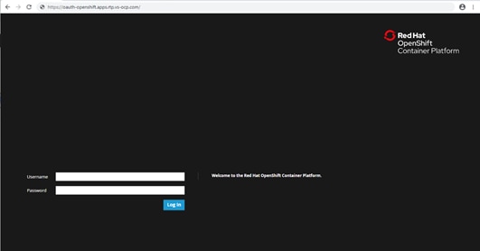
Go to Operators and select OperatorHub and search for Jenkins Operator.
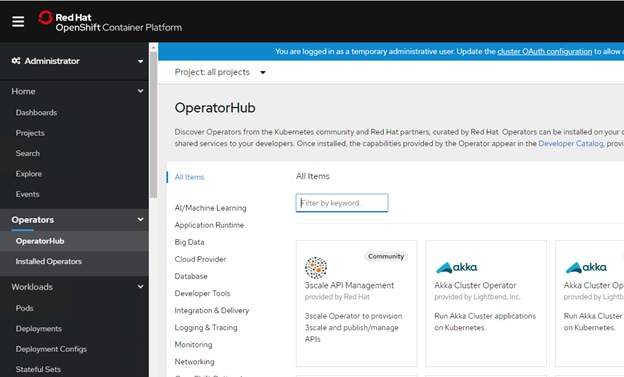
Select Jenkins Operator.
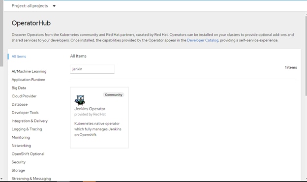
2. Click Install.
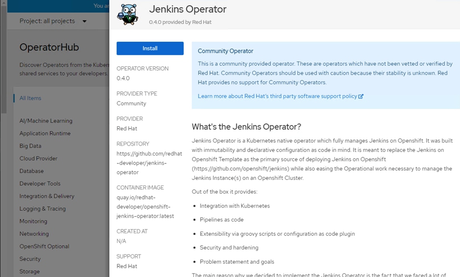
3. Click Subscribe for the Operator.
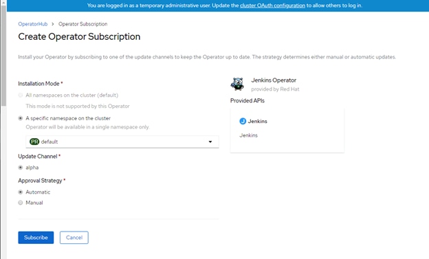
4. Wait for the Operator to get installed and display under your Installed Operators.
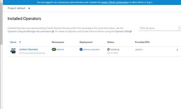
5. Verify the status is Succeeded.
6. Wait for the Operator to get installed and display under your Installed Operators.
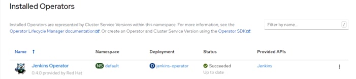
7. To create a Jenkins instance, click the Jenkins Operator as shown above and you will see the menu (shown below) and then click Create Instance in the Jenkins resource as shown below.
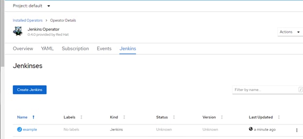
8. The following screen displays the options to make changes. We removed securityContext under the spec to avoid any authorization issues. Click Create to create a Jenkins instance.
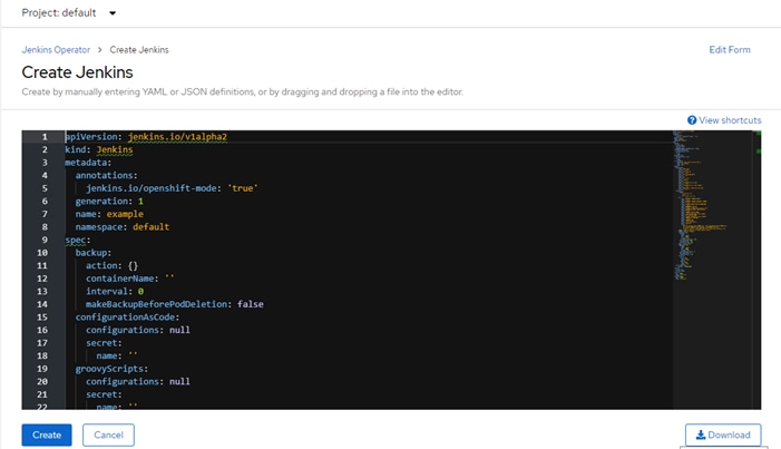
9. Jenkins Instance is shown below.
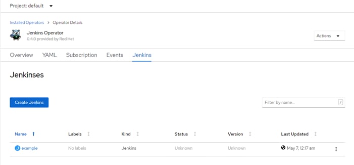
10. Login to OpenShift cluster using cli and verify the pods created.
# oc get pods -n default
NAME READY STATUS RESTARTS AGE
jenkins-example 1/1 Running 0 25s
jenkins-operator-5f64fd56f9-84d5k 1/1 Running 0 9m57s
Set up Jenkins instance to work with the right configuration necessary to run with Openshift as follows:
Add ClusterRole edit to the ServiceAccount used by the Jenkins instance created by the Operator.
# oc adm policy add-cluster-role-to-user edit -z jenkins-operator-example -n jenkins-operator-test
Warning: ServiceAccount 'jenkins-operator-example' not found
clusterrole.rbac.authorization.k8s.io/edit added: "jenkins-operator-example"
11. Expose the Service pointing to the Jenkins instance to be used as a Route so we can access the Jenkins instance from outside the Cluster Network.
12. Get the service which points to the Jenkins instance.
# oc get svc | grep jenkins-operator-http
jenkins-operator-http-example ClusterIP 172.30.143.252 <none> 8080/TCP 85s
13. Expose the Http Service pointing to the Jenkins instance via a Route.
# oc expose svc jenkins-operator-http-example
route.route.openshift.io/jenkins-operator-http-example exposed
14. Update the Route to use TLS Edge Termination and set the HA Proxy timeout.
# oc patch route jenkins-operator-http-example -p '{"spec":{"tls":{"insecureEdgeTerminationPolicy":"Redirect","termination":"edge"}}}'
route.route.openshift.io/jenkins-operator-http-example patched
# oc annotate route jenkins-operator-http-example "haproxy.router.openshift.io/timeout"="4m"
route.route.openshift.io/jenkins-operator-http-example annotated
15. Configure Jenkins instance ServiceAccount to be used for the Redirection.
# oc annotate sa jenkins-operator-example "serviceaccounts.openshift.io/oauth-redirectreference.jenkins"="{\"kind\":\"OAuthRedirectReference\",\"apiVersion\":\"v1\",\"reference\":{\"kind\":\"Route\",\"name\":\"jenkins-operator-http-example\"}}"
serviceaccount/jenkins-operator-example annotated
16. Verify the route to use to access the Jenkins service.
# oc get route | grep jenkins-operator-http
jenkins-operator-http-example jenkins-operator-http-example-default.apps.rtp.vs-ocp.com jenkins-operator-http-example 8080 edge/Redirect None
17. Using a browser go to the Route and log in via our OpenShift Credentials.
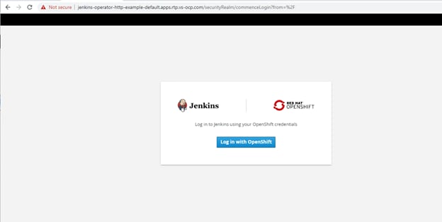
Jenkins logged in successfully as shown below:
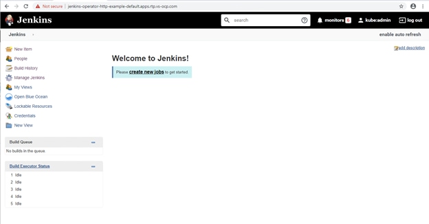
18. Create new build jobs in Jenkins with Git from the GUI or via CLI based on your preference.
Other Applications Validated
We deployed other sample applications on the OpenShift cluster during validation using the available operators. MongoDB and postgresql applications have been validated and tested for successful deployment along with persistent storage assigned from IBM FlashSystem dynamically.
cockroachDB
1. Pods deployed as part of the cockroachDB deployment.
# oc get pods -n turbo
NAME READY STATUS RESTARTS AGE
cockroachdb-5fbd549cbc-q2rdk 1/1 Running 0 2m58s
example-6zwh6g613qcht4m3ikksrbyyn-cdb-0 1/1 Running 0 111s
example-6zwh6g613qcht4m3ikksrbyyn-cdb-1 1/1 Running 0 110s
example-6zwh6g613qcht4m3ikksrbyyn-cdb-2 1/1 Running 0 110s
example-6zwh6g613qcht4m3ikksrbyyn-cdb-init-b5prb 0/1 Completed 0 111s
2. Persistent volume claims created for cockroachDB database pods.
# oc get pvc -n turbo
NAME STATUS VOLUME CAPACITY ACCESS MODES STORAGECLASS AGE
datadir-example-6zwh6g613qcht4m3ikksrbyyn-cdb-0 Bound pvc-361adcdf-8374-4788-a33e-d2568b2f344b 10Gi RWO ibmc-block-gold 108s
datadir-example-6zwh6g613qcht4m3ikksrbyyn-cdb-1 Bound pvc-fab4eb54-b150-4192-82f3-bcddddc38b05 10Gi RWO ibmc-block-gold 108s
datadir-example-6zwh6g613qcht4m3ikksrbyyn-cdb-2 Bound pvc-47554d3d-8b08-4b0b-a50e-17e46d261269 10Gi RWO ibmc-block-gold 107s
3. Persistent volumes created for cockroachDB database pods.
# oc get pv -n turbo
NAME CAPACITY ACCESS MODES RECLAIM POLICY STATUS CLAIM STORAGECLASS REASON AGE
6d4h
pvc-1922c730-61d4-40f9-84c0-bfedcb95b6d7 1Gi RWO Delete Bound default/www-web-1 ibmc-block-gold 4h7m
pvc-47554d3d-8b08-4b0b-a50e-17e46d261269 10Gi RWO Delete Bound turbo/datadir-example-6zwh6g613qcht4m3ikksrbyyn-cdb-2 ibmc-block-gold 11m
pvc-642473b4-e907-4407-b76a-0082c1e47fc2 1Gi RWO Delete Bound turbo/database ibmc-block-gold 2m20s
pvc-fab4eb54-b150-4192-82f3-bcddddc38b05 10Gi RWO Delete Bound turbo/datadir-example-6zwh6g613qcht4m3ikksrbyyn-cdb-1 ibmc-block-gold 11m
4. The view of corresponding volumes created on the IBM FlashSystem is shown below.
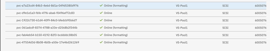
5. cockroachDB service displayed as follows:
[root@192 install]# oc get service -n turbo
NAME TYPE CLUSTER-IP EXTERNAL-IP PORT(S) AGE
example-6zwh6g613qcht4m3ikksrbyyn-cdb ClusterIP None <none> 26257/TCP,8080/TCP 8m21s
example-6zwh6g613qcht4m3ikksrbyyn-cdb-public ClusterIP 172.30.171.133 <none> 26257/TCP,8080/TCP 8m21s
mygresql database
1. Pod deployed as part of the mygresql deployment.
oc get pods -n turbo
NAME READY STATUS RESTARTS AGE
postgresql-operator-7848fb6bc6-5bhmk 1/1 Running 0 2m30s
2. Persistent volume claims created for mygresql database pods.
# oc get pvc -n turbo
NAME STATUS VOLUME CAPACITY ACCESS MODES STORAGECLASS AGE
database Bound pvc-642473b4-e907-4407-b76a-0082c1e47fc2 1Gi RWO ibmc-block-gold 9m57s
datadir-example-6zwh6g613qcht4m3ikksrbyyn-cdb-0 Bound pvc-361adcdf-8374-4788-a33e-d2568b2f344b
3. Persistent volumes created for mygresql database pods.
# oc get pv
NAME CAPACITY ACCESS MODES RECLAIM POLICY STATUS CLAIM STORAGECLASS REASON AGE
pvc-642473b4-e907-4407-b76a-0082c1e47fc2 1Gi RWO Delete Bound
4. Persistent volumes created for mygresql database pods.
[root@192 install]# oc get service
NAME TYPE CLUSTER-IP EXTERNAL-IP PORT(S) AGE
postgresql-operator-metrics ClusterIP 172.30.111.225 <none> 8383/TCP,8686/TCP 41s
5. The view of corresponding volume created on the IBM FlashSystem is show below.
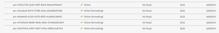
Deploy Applications Manually
We deployed a sample Ngnix web application as follows, the same application has been used to demonstrate application scaling later in the Validation section of the document.
1. The following YAML file has been used to deploy the application.
# cat web.yaml
apiVersion: v1
kind: Service
metadata:
name: nginx
labels:
app: nginx
spec:
ports:
- port: 80
name: web
clusterIP: None
selector:
app: nginx
---
apiVersion: apps/v1
kind: StatefulSet
metadata:
name: web
spec:
serviceName: "nginx"
replicas: 2
selector:
matchLabels:
app: nginx
template:
metadata:
labels:
app: nginx
spec:
containers:
- name: nginx
image: k8s.gcr.io/nginx-slim:0.8
ports:
- containerPort: 80
name: web
volumeMounts:
- name: www
mountPath: /usr/share/nginx/html
volumeClaimTemplates:
- metadata:
name: www
annotations:
volume.beta.kubernetes.io/storage-class:
spec:
accessModes: [ "ReadWriteOnce" ]
resources:
requests:
storage: 1Gi
2. Run the following command to install the application:
# oc create -f web.yaml
3. The following output shows the Pods, PVC’s and the PV’s created for the Ngnix with 2 replicas.
# oc get pods
NAME READY STATUS RESTARTS AGE
web-0 1/1 Running 0 4h34m
web-1 1/1 Running 0 4h34m
# oc get pvc
NAME STATUS VOLUME CAPACITY ACCESS MODES STORAGECLASS AGE
www-web-0 Bound pvc-d9e1e1a3-f6fe-47f6-aba6-f0496ef72c83 1Gi RWO ibmc-block-gold 4h34m
www-web-1 Bound pvc-1922c730-61d4-40f9-84c0-bfedcb95b6d7 1Gi RWO ibmc-block-gold 4h34m
# oc get pv
NAME CAPACITY ACCESS MODES RECLAIM POLICY STATUS CLAIM STORAGECLASS REASON AGE
default/www-web-1 ibmc-block-gold 4h31m
ibmc-block-gold 60m
pvc-d9e1e1a3-f6fe-47f6-aba6-f0496ef72c83 1Gi RWO Delete Bound default/www-web-0 ibmc-block-gold 4h31m
4. The view of the volumes created on the FlashSystem for Ngnix web application are shown below.
![]()
Red Hat OpenShift Container Platform Day-2 Operations
Add New Worker Node
Adding a Worker node is required to support additional workloads as the environment grows. When determined that additional worker node is needed, a new VM has to be created using the template and then added to the OpenShift cluster.
New Cluster
If you have a new installation of OpenShift cluster and want to add a worker node, follow these steps, otherwise go to the next section if more than 24 hours have passed after the cluster was initially installed:
1. Login to the management host and go to the terraform installation directory and go to the vsphere directory.
2. Update the DNS server with the new work node entry.
3. Update the terraform.tfvars file and add the new worker node IP address that you want to add to the cluster and change the number of worker nodes by incrementing the number by the number of nodes you want to add, in this case the total number will be 5.
compute_ips = ["10.1.162.14", "10.1.162.15", "10.1.162.16", "10.1.162.17", "10.1.162.18"]
compute_count = 5
4. Run terraform apply command to create the new worker machine
# terraform apply –auto-approve
5. Wait for the new worker node VM to complete booting.
6. From the management node, verify the status of the CSR, it may be required to manually approve the node's CSR (Certificate Signing Request) if they are in pending state
# oc get csr
NAME AGE REQUESTOR CONDITION
csr-695bc 46m system:serviceaccount:openshift-machine-config-operator:node-bootstrapper Pending
csr-8qwzp 99s system:serviceaccount:openshift-machine-config-operator:node-bootstrapper Pending
csr-ch99c 16m system:serviceaccount:openshift-machine-config-operator:node-bootstrapper Pending
csr-g9k9k 31m system:serviceaccount:openshift-machine-config-operator:node-bootstrapper Pending
7. Approve the CSRs for the new machine using the following command:
# oc get csr -o go-template='{{range .items}}{{if not .status}}{{.metadata.name}}{{"\n"}}{{end}}{{end}}' | xargs oc adm certificate approve
8. Confirm that the cluster recognizes the new machine, wait for the status to become ready:
[root@192 ocp43]# oc get nodes
NAME STATUS ROLES AGE VERSION
compute-0 Ready worker 3d21h v1.16.2
compute-1 Ready worker 3d21h v1.16.2
compute-2 Ready worker 3d21h v1.16.2
compute-3 Ready worker 3d21h v1.16.2
compute-4 Ready worker 107s v1.16.2
control-plane-0 Ready master 3d21h v1.16.2
control-plane-1 Ready master 3d21h v1.16.2
control-plane-2 Ready master 3d21h v1.16.2
9. Update the HAproxy server with the new work node entry, matching with the existing worker nodes.
10. The IBM CSI driver gets automatically installed on the new worker node.
oc get pods -n kube-system
NAME READY STATUS RESTARTS AGE
ibm-block-csi-controller-0 4/4 Running 0 3d5h
ibm-block-csi-node-5m2zz 3/3 Running 0 3d5h
ibm-block-csi-node-9f7lq 3/3 Running 0 3d5h
ibm-block-csi-node-g77p9 3/3 Running 0 3d5h
ibm-block-csi-node-jp6ks 3/3 Running 0 3d5h
ibm-block-csi-node-sfmg6 3/3 Running 0 80m
ibm-block-csi-operator-79c7c4b44f-cxlkz 1/1 Running 0 3d5h
11. Complete the necessary tasks to make sure the new worker node access iSCSI storage via the designated storage network.
Existing Cluster (installed more than 24 hours ago)
To add a new worker node if it’s been more than 24 hours since the cluster has been installed, follow these steps:
1. Update the DNS server with the new worker node entry, follow the same naming convention that was followed earlier.
Login to the management host and go to the OpenShift installation directory <ocp43>.
Make a backup of worker.ign.
#cp ./worker.ign ./worker.ign.backup
2. Run the following command, replace the domain name with the actual FQDN you are using:
#export MCS=api-int.rtp.vs-ocp:22623
3. Execute the following command which performs a series of tasks:
· Retrieves the certificate from the api-int.#{domain}:22623 and save in a temporary file.
· Encodes the certificate using base64 with "--wrap=0" option.
· Updates the content of api-int.base64 file to the worker.ign file.
# echo "q" | openssl s_client -connect #MCS -showcerts | awk '/-----BEGIN CERTIFICATE-----/,/-----END CERTIFICATE-----/' | base64 --wrap=0 | tee ./api-int.base64 && sed --regexp-extended --in-place=.backup "s%base64,[^,]+%base64,#(cat ./api-int.base64)\"%" ./worker.ign
4. Encode the worker.ign file using base64 command.
base64 -w0 worker.ign > worker.64
![]() The contents of the updated worker.64 file will be used while creating the new worker nodes.
The contents of the updated worker.64 file will be used while creating the new worker nodes.
5. Manually create a VM using the OVA template that was created earlier during installation of the cluster.
6. Right-click the template’s name and click Clone → Clone to Virtual Machine.
On the Select a name and folder tab, specify a name for the VM. You might include the machine type in the name, such as <compute-4>.
7. On the Select a name and folder tab, select the name of the folder that you created for the cluster.
8. On the Select a compute resource tab, select the name of a host in your datacenter.
9. Optional: On the Select storage tab, customize the storage options.
10. On the Select clone options, select Customize this virtual machine’s hardware.
11. On the Customize hardware tab, click VM Options > Advanced.
12. Click Edit Configuration and on the Configuration Parameters window, click Add Configuration Params. Define the following parameter names and values:
guestinfo.ignition.config.data: Paste the contents of the base64-encoded Ignition config file (worker.64) created earlier.
guestinfo.ignition.config.data.encoding: Specify base64.
disk.EnableUUID: Specify TRUE.
13. Complete the configuration and do not power on the VM.
14. Add the MAC address of the newly create worker node VM in the DHCP server configuration to assign a static IP address. Refer to example config below:
host compute-4 {
option host-name "compute-4.rtp.vs-ocp.com";
hardware ethernet 00:50:56:98:7b:56;
fixed-address 10.1.162.19;
}
15. Power on the VM and wait for the new worker node VM to complete booting.
16. From the management node, verify the status of the CSR, it may be required to manually approve the node's CSR (Certificate Signing Request) if they are in pending state
# oc get csr
NAME AGE REQUESTOR CONDITION
csr-695bc 46m system:serviceaccount:openshift-machine-config-operator:node-bootstrapper Pending
csr-8qwzp 99s system:serviceaccount:openshift-machine-config-operator:node-bootstrapper Pending
csr-ch99c 16m system:serviceaccount:openshift-machine-config-operator:node-bootstrapper Pending
csr-g9k9k 31m system:serviceaccount:openshift-machine-config-operator:node-bootstrapper Pending
17. Approve the CSRs for the new machine using the following command:
# oc get csr -o go-template='{{range .items}}{{if not .status}}{{.metadata.name}}{{"\n"}}{{end}}{{end}}' | xargs oc adm certificate approve
18. Confirm that the cluster recognizes the new machine, wait for the status to become ready:
[root@192 ocp43]# oc get nodes
NAME STATUS ROLES AGE VERSION
compute-0 Ready worker 3d21h v1.16.2
compute-1 Ready worker 3d21h v1.16.2
compute-2 Ready worker 3d21h v1.16.2
compute-3 Ready worker 3d21h v1.16.2
compute-4 Ready worker 107s v1.16.2
control-plane-0 Ready master 3d21h v1.16.2
control-plane-1 Ready master 3d21h v1.16.2
control-plane-2 Ready master 3d21h v1.16.2
19. Update the HAproxy server with the new work node entry, matching with the existing worker nodes.
20. The IBM CSI driver gets automatically installed on the new worker node.
oc get pods -n kube-system
NAME READY STATUS RESTARTS AGE
ibm-block-csi-controller-0 4/4 Running 0 3d5h
ibm-block-csi-node-5m2zz 3/3 Running 0 3d5h
ibm-block-csi-node-9f7lq 3/3 Running 0 3d5h
ibm-block-csi-node-g77p9 3/3 Running 0 3d5h
ibm-block-csi-node-jp6ks 3/3 Running 0 3d5h
ibm-block-csi-node-sfmg6 3/3 Running 0 80m
ibm-block-csi-operator-79c7c4b44f-cxlkz 1/1 Running 0 3d5h
21. Complete the necessary tasks to make sure the new worker node can access iSCSI storage via the designated storage network.
![]() The above procedure used a reserved DHCP IP address for the new worker node. If a static IP address is preferred, follow the Red Hat documentation: https://docs.openshift.com/container-platform/4.3/installing/installing_bare_metal/installing-bare-metal.html#creating-machines-bare-metal to create a new node with static IP address or use the machine config operator to assign the IP address statically.
The above procedure used a reserved DHCP IP address for the new worker node. If a static IP address is preferred, follow the Red Hat documentation: https://docs.openshift.com/container-platform/4.3/installing/installing_bare_metal/installing-bare-metal.html#creating-machines-bare-metal to create a new node with static IP address or use the machine config operator to assign the IP address statically.
Remove Worker Node
Removing a Worker node can be done by running the uninstall script from:
To delete a node from the OpenShift Container Platform cluster, edit the appropriate MachineSet by following these steps:
1. View the MachineSets that are in the cluster:
# oc get machinesets -n openshift-machine-api
2. The MachineSets are listed in the form of <clusterid>-worker-<aws-region-az>.
3. Scale the MachineSet:
# oc scale --replicas=2 machineset <machineset> -n openshift-machine-api
OpenShift Monitoring
OpenShift Container Platform includes a pre-configured, pre-installed, and self-updating monitoring stack that is based on the Prometheus open source project and its wider eco-system. It provides monitoring of cluster components and includes a set of alerts to immediately notify the cluster administrator about any occurring problems and a set of Grafana dashboards. The cluster monitoring stack is only supported for monitoring OpenShift Container Platform clusters.
To access Prometheus, Alerting UI, and Grafana using the OpenShift Container Platform web console, follow these steps:
1. Navigate to the OpenShift Container Platform web console and authenticate.
· To access Prometheus, navigate to the "Monitoring" → "Metrics" page.
· To access the Alerting UI, navigate to the "Monitoring" → "Alerting" page.
· To access Grafana, navigate to the "Monitoring" → "Dashboards" page.
![]() Prometheus, Alertmanager, and Grafana web UIs can also be accessed directly using the oc tool and a web browser as follows:
Prometheus, Alertmanager, and Grafana web UIs can also be accessed directly using the oc tool and a web browser as follows:
2. From the management host, to verify the routes for all management components:
# oc -n openshift-monitoring get routes
NAME HOST/PORT PATH SERVICES PORT TERMINATION WILDCARD
alertmanager-main alertmanager-main-openshift-monitoring.apps.rtp.vs-ocp.com alertmanager-main web reencrypt/Redirect None
grafana grafana-openshift-monitoring.apps.rtp.vs-ocp.com grafana https reencrypt/Redirect None
prometheus-k8s prometheus-k8s-openshift-monitoring.apps.rtp.vs-ocp.com prometheus-k8s web reencrypt/Redirect None
thanos-querier thanos-querier-openshift-monitoring.apps.rtp.vs-ocp.com thanos-querier web reencrypt/Redirect None
3. Navigate to the address using a web browser and authenticate.
4. The URLs from the above output will be used to login and access the different monitoring components.
Grafana
1. Open a web browser and paste in the Grafana URL
Log in as kubeadmin or as a user with cluster admin privileges.
2. Click DashBoard and manage icon.
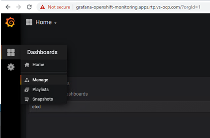
3. A list of items will be displayed that can be managed.
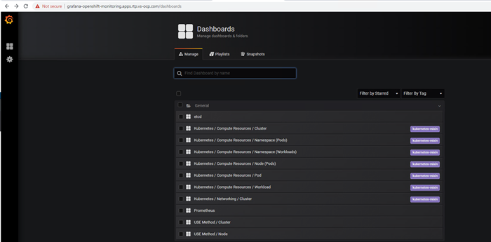
4. Select etcd for example and verify the dashboard showing the active streams, number of etcd nodes up, and other details, as shown below.
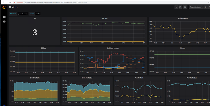
Prometheus
1. Open a web browser and paste in the Prometheus URL.
Log in as kubeadmin or as a user with cluster admin privileges.
2. From the Execute menu, select one of the available queries and click Execute.
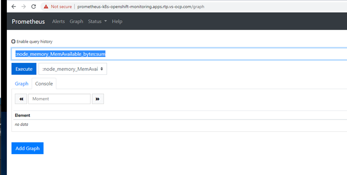
3. Select the graph tab to view the selected query as shown below.
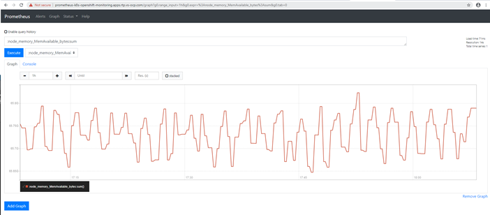
Alert Manager
1. Open a web browser and paste in the Prometheus URL
Log in as kubeadmin or as a user with cluster admin privileges.
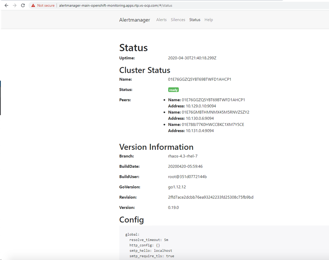
Test Plan
This section provides the details about additional tests conducted by the team, validating the design, and the implementation aspects of this solution.
A high-level summary of the VersaStack Datacenter with Red Hat OpenShift Container Platform validation is provided in this section.
VersaStack Infrastructure Validation
The system was validated for resiliency by failing various aspects of the system under load. Examples of the types of tests executed include:
· Failure and recovery of iSCSI booted ESXi hosts in a cluster
· Rebooting of iSCSI booted hosts
· Service Profile migration between blades
· Failure of partial and complete IOM links
· Failure and recovery of iSCSI paths to IBM FlashSystem nodes, Nexus switches, and fabric interconnects
IBM CSI Block Storage Driver Validation
Creation, deletion and management of persistent volumes manually and as part of the application deployment.
Red Hat OpenShift Container Platform Environment Validation
The following aspects were tested and validated:
Applications deployment as covered in the deployment section and scaling of applications as covered in below section.
Scaling Deployments
Applications need to scale up and down based on the business needs of the customers; we scaled-up the Ngnix application that we deployed earlier to demonstrate the application scalability.
To scale a deployment, follow these steps:
1. The Ngnix application status from previous deployment, as installed earlier in the deployment section.
# oc get pods
NAME READY STATUS RESTARTS AGE
web-0 1/1 Running 0 4h34m
web-1 1/1 Running 0 4h34m
2. The Ngnix application was initially deployed with 2 replicas and we scaled the application to 100 (increased the replicas to 100).
# oc scale sts web --replicas=100
statefulset.apps/web scaled
3. Below is the Nginx application being scaled with 100 replicas.
# oc get pods |grep web| wc -l
100
# oc get pods |grep web
web-0 1/1 Running 0 5h16m
web-1 1/1 Running 0 5h16m
web-10 1/1 Running 0 27m
web-11 1/1 Running 0 27m
web-12 1/1 Running 0 27m
web-13 1/1 Running 0 27m
web-14 1/1 Running 0 26m
web-15 1/1 Running 0 26m
web-16 1/1 Running 0 26m
web-17 1/1 Running 0 25m
web-18 1/1 Running 0 25m
web-19 1/1 Running 0 25m
web-2 1/1 Running 0 31m
web-20 1/1 Running 0 24m
web-21 1/1 Running 0 24m
web-22 1/1 Running 0 24m
web-23 1/1 Running 0 23m
web-24 1/1 Running 0 23m
web-25 1/1 Running 0 23m
web-26 1/1 Running 0 23m
web-27 1/1 Running 0 22m
web-28 1/1 Running 0 22m
web-29 1/1 Running 0 22m
web-3 1/1 Running 0 30m
web-30 1/1 Running 0 21m
web-31 1/1 Running 0 21m
web-32 1/1 Running 0 21m
web-33 1/1 Running 0 21m
web-34 1/1 Running 0 20m
web-35 1/1 Running 0 20m
web-36 1/1 Running 0 20m
web-37 1/1 Running 0 19m
web-38 1/1 Running 0 19m
web-39 1/1 Running 0 19m
web-4 1/1 Running 0 29m
web-40 1/1 Running 0 18m
web-41 1/1 Running 0 18m
web-42 1/1 Running 0 18m
web-43 1/1 Running 0 17m
web-44 1/1 Running 0 17m
web-45 1/1 Running 0 17m
web-46 1/1 Running 0 17m
web-47 1/1 Running 0 16m
web-48 1/1 Running 0 16m
web-49 1/1 Running 0 16m
web-5 1/1 Running 0 29m
web-50 1/1 Running 0 15m
web-51 1/1 Running 0 15m
web-52 1/1 Running 0 15m
web-53 1/1 Running 0 14m
web-54 1/1 Running 0 14m
web-55 1/1 Running 0 14m
web-56 1/1 Running 0 14m
web-57 1/1 Running 0 13m
web-58 1/1 Running 0 13m
web-59 1/1 Running 0 13m
web-6 1/1 Running 0 29m
web-60 1/1 Running 0 12m
web-61 1/1 Running 0 12m
web-62 1/1 Running 0 12m
web-63 1/1 Running 0 12m
web-64 1/1 Running 0 11m
web-65 1/1 Running 0 11m
web-66 1/1 Running 0 11m
web-67 1/1 Running 0 10m
web-68 1/1 Running 0 10m
web-69 1/1 Running 0 9m57s
web-7 1/1 Running 0 28m
web-70 1/1 Running 0 9m40s
web-71 1/1 Running 0 9m26s
web-72 1/1 Running 0 9m11s
web-73 1/1 Running 0 8m53s
web-74 1/1 Running 0 8m25s
web-75 1/1 Running 0 8m12s
web-76 1/1 Running 0 7m52s
web-77 1/1 Running 0 7m38s
web-78 1/1 Running 0 7m19s
web-79 1/1 Running 0 6m51s
web-8 1/1 Running 0 28m
web-80 1/1 Running 0 6m38s
web-81 1/1 Running 0 6m24s
web-82 1/1 Running 0 6m5s
web-83 1/1 Running 0 5m51s
web-84 1/1 Running 0 5m26s
web-85 1/1 Running 0 5m7s
web-86 1/1 Running 0 4m52s
web-87 1/1 Running 0 4m34s
web-88 1/1 Running 0 4m7s
web-89 1/1 Running 0 3m41s
web-9 1/1 Running 0 28m
web-90 1/1 Running 0 3m23s
web-91 1/1 Running 0 2m57s
web-92 1/1 Running 0 2m37s
web-93 1/1 Running 0 2m22s
web-94 1/1 Running 0 2m8s
web-95 1/1 Running 0 113s
web-96 1/1 Running 0 100s
web-97 1/1 Running 0 74s
web-98 1/1 Running 0 61s
web-99 1/1 Running 0 45s
4. Below is the list of PVC’s associated with the Nginx pods.
# oc get pvc
www-web-0 Bound pvc-d9e1e1a3-f6fe-47f6-aba6-f0496ef72c83 1Gi RWO ibmc-block-gold 5h18m
www-web-1 Bound pvc-1922c730-61d4-40f9-84c0-bfedcb95b6d7 1Gi RWO ibmc-block-gold 5h18m
www-web-10 Bound pvc-22b07910-55ba-4eae-a3b0-eb570c92c72f 1Gi RWO ibmc-block-gold 29m
www-web-11 Bound pvc-4c0eed5f-a966-4bc8-b384-7743ac690386 1Gi RWO ibmc-block-gold 29m
www-web-12 Bound pvc-85cedfc0-9b85-46c4-82dc-acac265438cd 1Gi RWO ibmc-block-gold 29m
www-web-13 Bound pvc-96968ad6-6d6e-4018-99fd-61a8cf438c28 1Gi RWO ibmc-block-gold 28m
www-web-14 Bound pvc-86b670fa-eb2c-4170-b4c9-ee457017c12b 1Gi RWO ibmc-block-gold 28m
www-web-15 Bound pvc-baf647a9-16de-46f8-abe6-cdeb654c67a7 1Gi RWO ibmc-block-gold 28m
www-web-16 Bound pvc-72d2cbfe-abe5-486f-9be2-192edbf8c3c1 1Gi RWO ibmc-block-gold 28m
www-web-17 Bound pvc-6eb69a0b-5033-4de1-abda-4b0389756c1d 1Gi RWO ibmc-block-gold 27m
www-web-18 Bound pvc-2bf62eee-8597-4d72-865e-0ed65b39e45c 1Gi RWO ibmc-block-gold 27m
www-web-19 Bound pvc-8d3d2fc0-d1c1-4672-a112-c698b11d1321 1Gi RWO ibmc-block-gold 27m
www-web-2 Bound pvc-65e9fc36-261b-4b7c-958f-6f97fb3bc21a 1Gi RWO ibmc-block-gold 33m
www-web-20 Bound pvc-83509b6f-75b4-477d-a490-3cecc95facdf 1Gi RWO ibmc-block-gold 26m
www-web-21 Bound pvc-e3000c2c-5efc-4ff0-a39f-198d735c5464 1Gi RWO ibmc-block-gold 26m
www-web-22 Bound pvc-6c794156-166a-424f-9f75-aa5ab81f5823 1Gi RWO ibmc-block-gold 26m
www-web-23 Bound pvc-15d1e35c-da53-49a4-a4a3-630df37deeef 1Gi RWO ibmc-block-gold 25m
www-web-24 Bound pvc-c9b5d70c-4bbd-4452-b435-ef57f09171df 1Gi RWO ibmc-block-gold 25m
www-web-25 Bound pvc-31244bac-b3e2-49a9-b4e7-e25a237ab585 1Gi RWO ibmc-block-gold 25m
www-web-26 Bound pvc-047f4815-9908-4cc4-b564-85783b4458b6 1Gi RWO ibmc-block-gold 24m
www-web-27 Bound pvc-a08eaab7-5eab-452f-b98c-a5d107b75fa1 1Gi RWO ibmc-block-gold 24m
www-web-28 Bound pvc-06dfd139-ff72-42e2-a8de-104b235b5235 1Gi RWO ibmc-block-gold 24m
www-web-29 Bound pvc-d3343307-2d9a-42e8-b53f-489b1bf4a2ee 1Gi RWO ibmc-block-gold 24m
www-web-3 Bound pvc-f82cc958-2c56-4f2b-973a-c9771f4b75a2 1Gi RWO ibmc-block-gold 32m
www-web-30 Bound pvc-19727c25-a117-41f6-a296-71666aabd8d2 1Gi RWO ibmc-block-gold 23m
www-web-31 Bound pvc-a8d08922-60a0-458e-8069-20c388490f7e 1Gi RWO ibmc-block-gold 23m
www-web-32 Bound pvc-a1c1ccd7-32b5-436f-9332-f58e703206a5 1Gi RWO ibmc-block-gold 23m
www-web-33 Bound pvc-cf387eee-73c1-432d-8dff-0779a11f1938 1Gi RWO ibmc-block-gold 23m
www-web-34 Bound pvc-34957d96-5329-464f-988c-2eafa8d4c08f 1Gi RWO ibmc-block-gold 22m
www-web-35 Bound pvc-1d39e0cd-9c3d-4649-a502-0fdb3d3087cf 1Gi RWO ibmc-block-gold 22m
www-web-36 Bound pvc-b7274df6-df20-4d39-bbb2-cf6b1616ced0 1Gi RWO ibmc-block-gold 22m
www-web-37 Bound pvc-d35aa428-179f-4293-b993-fdd95c18adbf 1Gi RWO ibmc-block-gold 21m
www-web-38 Bound pvc-257ada09-67b4-48ca-a555-7ad6f9dbbe5f 1Gi RWO ibmc-block-gold 21m
www-web-39 Bound pvc-91556005-b11f-409f-8b14-f5df4992b234 1Gi RWO ibmc-block-gold 21m
www-web-4 Bound pvc-c1ec099d-2131-40d3-b7c6-c93094fec968 1Gi RWO ibmc-block-gold 31m
www-web-40 Bound pvc-5a4b9a71-d88d-4159-9da8-7ccd162d5e37 1Gi RWO ibmc-block-gold 20m
www-web-41 Bound pvc-d7d4e686-4faf-4fb6-943e-af375169e7d6 1Gi RWO ibmc-block-gold 20m
www-web-42 Bound pvc-3cac6486-9c78-4f68-90f7-aec3cd761dbb 1Gi RWO ibmc-block-gold 20m
www-web-43 Bound pvc-687163d7-514c-4864-9639-794145445658 1Gi RWO ibmc-block-gold 19m
www-web-44 Bound pvc-6be74053-6e3a-46f5-ba89-d1fb82d8e1f4 1Gi RWO ibmc-block-gold 19m
www-web-45 Bound pvc-98edc4d7-8471-4489-8bae-1bd5399b5b25 1Gi RWO ibmc-block-gold 19m
www-web-46 Bound pvc-c0bdd252-41c9-45ef-9c58-4bea7c9efb50 1Gi RWO ibmc-block-gold 19m
www-web-47 Bound pvc-941135ef-12c5-4e6b-aca6-149308592c88 1Gi RWO ibmc-block-gold 18m
www-web-48 Bound pvc-619595dc-a334-4ad5-bd37-8d526edba4f1 1Gi RWO ibmc-block-gold 18m
www-web-49 Bound pvc-997c73ae-399d-4a81-bb2c-7e41c43def82 1Gi RWO ibmc-block-gold 18m
www-web-5 Bound pvc-3169f4cb-375e-4c68-b190-ff17c3773c15 1Gi RWO ibmc-block-gold 31m
www-web-50 Bound pvc-dae08f62-a509-4c39-bb65-3a6e817637d4 1Gi RWO ibmc-block-gold 17m
www-web-51 Bound pvc-9ad352d1-ebec-4886-9042-94dde198f00c 1Gi RWO ibmc-block-gold 17m
www-web-52 Bound pvc-ff81113f-90a4-47fd-8099-337f78ecb0b6 1Gi RWO ibmc-block-gold 17m
www-web-53 Bound pvc-6a64f2fb-4a57-4c49-9507-c75109d4fbd1 1Gi RWO ibmc-block-gold 16m
www-web-54 Bound pvc-f9d6e635-fed5-41fe-9843-3a894a99840d 1Gi RWO ibmc-block-gold 16m
www-web-55 Bound pvc-c759933e-c414-47a2-beed-c2698541fc93 1Gi RWO ibmc-block-gold 16m
www-web-56 Bound pvc-58dd3e36-811c-4416-a008-67de9972a7f5 1Gi RWO ibmc-block-gold 16m
www-web-57 Bound pvc-52d48ead-646d-45fe-87fb-7948401b4294 1Gi RWO ibmc-block-gold 15m
www-web-58 Bound pvc-2765b1e1-7e07-44ad-a34f-8a2c4cb85452 1Gi RWO ibmc-block-gold 15m
www-web-59 Bound pvc-3380945e-73fc-4d0f-8226-2e4ee8ddacd6 1Gi RWO ibmc-block-gold 15m
www-web-6 Bound pvc-f52e81b2-9e0b-4a9e-ae06-750158f1f4d8 1Gi RWO ibmc-block-gold 30m
www-web-60 Bound pvc-4d8452d5-cfa4-4e0d-9e90-3d1f45318b4f 1Gi RWO ibmc-block-gold 14m
www-web-61 Bound pvc-5970de95-23e5-49d5-a14c-181357cdf181 1Gi RWO ibmc-block-gold 14m
www-web-62 Bound pvc-803c9f0c-5b20-4acb-93d5-c9892d45052a 1Gi RWO ibmc-block-gold 14m
www-web-63 Bound pvc-5ebddfa5-2174-4f1e-b78e-313ec4e86fc3 1Gi RWO ibmc-block-gold 13m
www-web-64 Bound pvc-c92aae25-826e-4357-bd80-6b1c1a7376ea 1Gi RWO ibmc-block-gold 13m
www-web-65 Bound pvc-84bec844-4b31-451d-bab9-af994c868e4c 1Gi RWO ibmc-block-gold 13m
www-web-66 Bound pvc-74bae723-48c1-4151-9767-a2bc84692dcf 1Gi RWO ibmc-block-gold 13m
www-web-67 Bound pvc-2250b1e0-e485-4ea3-9b0c-7a2ddcf2b2e5 1Gi RWO ibmc-block-gold 12m
www-web-68 Bound pvc-07604a02-e382-4825-8e4a-904f5b75581e 1Gi RWO ibmc-block-gold 12m
www-web-69 Bound pvc-c71f020b-d356-41e2-b2fa-a8aa0b3989da 1Gi RWO ibmc-block-gold 11m
www-web-7 Bound pvc-8812a090-e159-4f40-a56d-9112467c6bbb 1Gi RWO ibmc-block-gold 30m
www-web-70 Bound pvc-e2be4888-1ab5-4392-a121-8c41d6d199f7 1Gi RWO ibmc-block-gold 11m
www-web-71 Bound pvc-7ae3bdd7-d5bf-48ba-8238-6749006489ca 1Gi RWO ibmc-block-gold 11m
www-web-72 Bound pvc-4e64fafe-7fdb-4c81-87e9-b652e2cf62f6 1Gi RWO ibmc-block-gold 11m
www-web-73 Bound pvc-817302ba-5268-41e0-89c0-b7ee1fe8d865 1Gi RWO ibmc-block-gold 10m
www-web-74 Bound pvc-b605f7cb-2c99-4e5a-8ec9-e6d9c314c957 1Gi RWO ibmc-block-gold 10m
www-web-75 Bound pvc-f6f8d79e-5c29-4525-886e-ee9dd79d0b70 1Gi RWO ibmc-block-gold 10m
www-web-76 Bound pvc-c090c984-21bd-49e0-9aed-abd7d17e9b57 1Gi RWO ibmc-block-gold 9m48s
www-web-77 Bound pvc-a3b276a2-5533-4303-8d69-ff09427ba77c 1Gi RWO ibmc-block-gold 9m34s
www-web-78 Bound pvc-387d4f62-c2ea-4cc2-8a25-c97cf58ef1d4 1Gi RWO ibmc-block-gold 9m15s
www-web-79 Bound pvc-9b464c36-af5e-455a-aa8d-fbaeb90c2e96 1Gi RWO ibmc-block-gold 8m47s
www-web-8 Bound pvc-3dc83c77-54dc-4ef4-9315-f726b1048b70 1Gi RWO ibmc-block-gold 30m
www-web-80 Bound pvc-5c4d8968-bd73-4af4-b775-9bee147e4638 1Gi RWO ibmc-block-gold 8m34s
www-web-81 Bound pvc-5d3c7118-a637-4fd2-9fd0-ddafbbf2b0a2 1Gi RWO ibmc-block-gold 8m20s
www-web-82 Bound pvc-7a7609db-54c1-44c4-bb56-8e3e7ccd0943 1Gi RWO ibmc-block-gold 8m1s
www-web-83 Bound pvc-c90febfa-3ad9-49de-ac08-8f59d24780cc 1Gi RWO ibmc-block-gold 7m47s
www-web-84 Bound pvc-98c1b9f3-e467-4b5f-82e8-79cab8a26721 1Gi RWO ibmc-block-gold 7m22s
www-web-85 Bound pvc-4a68f60f-f735-4d0f-a44c-ebc93c593ded 1Gi RWO ibmc-block-gold 7m3s
www-web-86 Bound pvc-8d3c140c-cbfc-40ee-94eb-0bb8caf76259 1Gi RWO ibmc-block-gold 6m48s
www-web-87 Bound pvc-460dd452-bc7a-4ca8-aa0c-1da502493e5c 1Gi RWO ibmc-block-gold 6m30s
www-web-88 Bound pvc-608d46a6-e7aa-4db6-ba6d-bafc2696311f 1Gi RWO ibmc-block-gold 6m3s
www-web-89 Bound pvc-4da8cada-e1cf-42c6-8ed0-14033379bea8 1Gi RWO ibmc-block-gold 5m37s
www-web-9 Bound pvc-9edfced5-e170-4047-a35b-0ea511aba78f 1Gi RWO ibmc-block-gold 30m
www-web-90 Bound pvc-2ee1a480-b899-45c5-98ee-8aa7ce11eafc 1Gi RWO ibmc-block-gold 5m19s
www-web-91 Bound pvc-c4310f13-365e-4a95-927b-a6d9eca73a2c 1Gi RWO ibmc-block-gold 4m53s
www-web-92 Bound pvc-232317eb-9c79-4149-bb5c-3dc40a7bc66c 1Gi RWO ibmc-block-gold 4m33s
www-web-93 Bound pvc-5fae7aec-9886-4276-bf7f-f405312cdb3e 1Gi RWO ibmc-block-gold 4m18s
www-web-94 Bound pvc-e3ac789d-9e4e-48d9-a645-4ac07f36e62e 1Gi RWO ibmc-block-gold 4m4s
www-web-95 Bound pvc-713a1ea2-91f3-489e-9132-1424aeb85610 1Gi RWO ibmc-block-gold 3m49s
www-web-96 Bound pvc-7329805a-a9b2-4f4e-83b0-51324bbbcce6 1Gi RWO ibmc-block-gold 3m36s
www-web-97 Bound pvc-6274809d-4f0d-48f0-8595-4172e949c0f8 1Gi RWO ibmc-block-gold 3m10s
www-web-98 Bound pvc-f40a1dc0-a92f-490b-b966-fb44899d363b 1Gi RWO ibmc-block-gold 2m57s
www-web-99 Bound pvc-786568e3-5bed-4362-9aa6-8e2524b5ac3b 1Gi RWO ibmc-block-gold 2m41s
5. Below is the view of volumes created on the IBM FlashSystem dynamically with the help of IBM CSI driver for block storage.
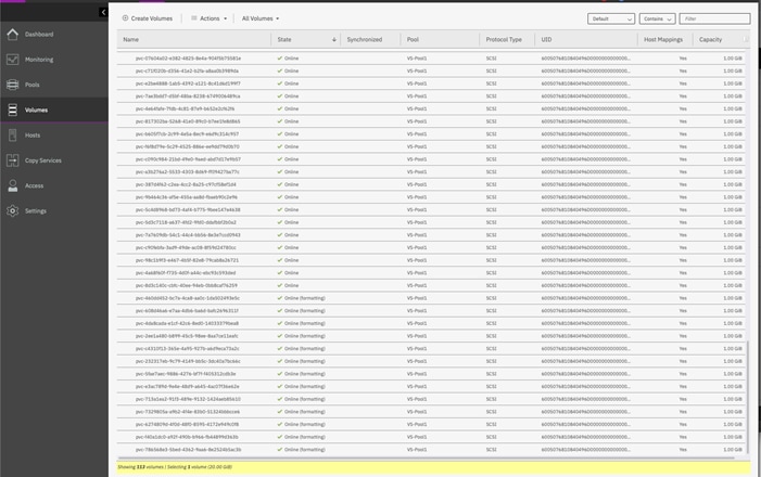
OpenShift Container Platform Benchmarking with Ripsaw
Baselining is a critical aspect of any infrastructure reliability. Ripsaw is a performance benchmark Operator for launching workloads on Kubernetes. It deploys as a Kubernetes Operator that then deploys common workloads, including specific applications (e.g., Couchbase) or general performance tests (for example, Sysbench) to measure and establish a performance baseline.
Ripsaw is maintained on GitHub. You can also find its maintainers on the Kubernetes Slack, where they are active contributors.
We performed basic benchmarking of resources with OpenShift installed on VersaStack. The displayed results should by no means be referenced to derive at the performance capabilities of the VersaStack. The tests have been performed with many PODs running on the system which were generating load simultaneously during the time we ran the ripsaw tests.
To install and configure Ripsaw if you want to perform benchmarking of your system, follow these steps:
1. From the management host, create a directory and clone the operator to that directory:
# mkdir /benchmark
# cd /benchmark
# git clone https://github.com/cloud-bulldozer/ripsaw
# cd ripsaw
export KUBECONFIG=<your_kube_config> # if not already done
2. All resources created/required by ripsaw are in the namespace my-ripsaw, as this would be the namespace, ripsaw would be installed into if deployed through operatorhub.io.
3. Create the namespace as follows.
# kubectl apply -f resources/namespace.yaml
4. Apply the permissions and operator definitions.
# kubectl apply -f deploy
# kubectl apply -f resources/crds/ripsaw_v1alpha1_ripsaw_crd.yaml
# kubectl apply -f resources/operator.yaml
5. Operator deployment is completed, follow workload specific instructions to run workloads.
6. Sysbench provides benchmarking capabilities for Linux. sysbench supports testing CPU, memory, file I/O, mutex performance, and even MySQL benchmarking.
7. Create a yaml file to test interested resources.
![]() The following yaml files are very basic tests, the parameters needs to be adjusted for the specific that you want to run:
The following yaml files are very basic tests, the parameters needs to be adjusted for the specific that you want to run:
Sample yaml file to test CPU:
apiVersion: ripsaw.cloudbulldozer.io/v1alpha1
kind: Benchmark
metadata:
name: sysbench-benchmark
namespace: my-ripsaw
spec:
workload:
name: sysbench
args:
enabled: true
#kind: vm
# If you want to run this as a VM uncomment the above
tests:
- name: cpu
parameters:
cpu-max-prime: 100
sysbench 1.0.17 (using system LuaJIT 2.1.0-beta3)
Running the test with following options:
Number of threads: 1
Initializing random number generator from current time
Prime numbers limit: 2000
Initializing worker threads...
WARNING: the --test option is deprecated. You can pass a script name or path on the command line without any options.
Threads started!
CPU speed:
events per second: 8653.11
General statistics:
total time: 10.0001s
total number of events: 86547
Latency (ms):
min: 0.11
avg: 0.11
max: 17.88
95th percentile: 0.12
sum: 9951.50
Threads fairness:
events (avg/stddev): 86547.0000/0.00
execution time (avg/stddev): 9.9515/0.00
Sample yaml file to test Memory:
apiVersion: ripsaw.cloudbulldozer.io/v1alpha1
kind: Benchmark
metadata:
name: sysbench-benchmark
namespace: my-ripsaw
spec:
workload:
name: sysbench
args:
enabled: true
#kind: vm
# If you want to run this as a VM uncomment the above
tests:
- name: memory
parameters:
memory-block-size: 1M
memory-total-size: 100G
8. When done creating/editing the resource file, run it as follows:
# kubectl apply -f <path_to_file>
9. Deploying the above would result in the following (example for memory)
# kubectl get pods -n my-ripsaw
NAME READY STATUS RESTARTS AGE
benchmark-operator-59fc46d5d5-b5vxh 3/3 Running 0 10d
sysbench-2f8f5db4-nksf6 0/1 ContainerCreating 0 1s
10. You can look at results by using logs functionality, it should look like the following:
# kubectl logs < sysbench-2f8f5db4-nksf6>
Results for CPU test:
sysbench 1.0.17 (using system LuaJIT 2.1.0-beta3)
Running the test with following options:
Number of threads: 1
Initializing random number generator from current time
Prime numbers limit: 2000
Initializing worker threads...
Threads started!
CPU speed:
events per second: 8601.48
General statistics:
total time: 10.0001s
total number of events: 86031
Latency (ms):
min: 0.11
avg: 0.12
max: 5.37
95th percentile: 0.12
sum: 9980.97
Threads fairness:
events (avg/stddev): 86031.0000/0.00
execution time (avg/stddev): 9.9810/0.00
Results for memory test:
sysbench 1.0.17 (using system LuaJIT 2.1.0-beta3)
Running the test with following options:
Number of threads: 1
Initializing random number generator from current time
Running memory speed test with the following options:
block size: 1024KiB
total size: 102400MiB
operation: write
scope: global
Initializing worker threads...
Threads started!
Total operations: 102400 (13635.80 per second)
102400.00 MiB transferred (13635.80 MiB/sec)
General statistics:
total time: 7.5079s
total number of events: 102400
Latency (ms):
min: 0.07
avg: 0.07
max: 4.14
95th percentile: 0.08
sum: 7475.91
Threads fairness:
events (avg/stddev): 102400.0000/0.00
execution time (avg/stddev): 7.4759/
Products and Solutions
Red Hat OpenShift:
IBM CSI Block Storage Driver:
https://github.com/IBM/ibm-block-csi-driver
Cisco Unified Computing System:
http://www.cisco.com/en/US/products/ps10265/index.html
Cisco UCS 6400 Series Fabric Interconnects:
Cisco UCS 5100 Series Blade Server Chassis:
http://www.isco.com/en/US/products/ps10279/index.html
Cisco UCS B-Series Blade Servers:
Cisco UCS C-Series Rack Servers:
http://www.cisco.com/c/en/us/products/servers-unified-computing/ucs-c-series-rack-servers/index.html
Cisco UCS Adapters:
http://www.cisco.com/en/US/products/ps10277/prod_module_series_home.html
Cisco UCS Manager:
http://www.cisco.com/en/US/products/ps10281/index.html
Cisco Intersight:
https://www.cisco.com/c/en/us/products/servers-unified-computing/intersight/index.html
Cisco Nexus 9000 Series Switches:
Cisco Application Centric Infrastructure:
Cisco Data Center Network Manager:
Cisco UCS Director:
https://www.cisco.com/c/en/us/products/servers-unified-computing/ucs-director/index.html
VMware vCenter Server:
http://www.vmware.com/products/vcenter-server/overview.html
VMware vSphere:
https://www.vmware.com/tryvmware_tpl/vsphere-55_evalcenter.html
https://www.ibm.com/it-infrastructure/storage/flash
IBM Cloud Paks:
https://www.ibm.com/cloud/paks/
Interoperability Matrixes
Cisco UCS Hardware Compatibility Matrix:
VMware and Cisco Unified Computing System:
http://www.vmware.com/resources/compatibility
IBM System Storage Interoperation Center:
http://www-03.ibm.com/systems/support/storage/ssic/interoperability.wss
This solution design based on Cisco VersaStack User Provisioned Infrastructure for Red Hat OpenShift Container Platform 4.3 is optimal for production-ready deployment processes with latest best practices, a stable, highly available environment to run enterprise-grade application containers.
VersaStack is the optimal shared infrastructure foundation to deploy a variety of IT workloads. It is built on leading computing, networking, storage, and infrastructure software components. The integration of VersaStack converged infrastructure with OpenShift Container Platform provides a very good starting point for enterprise IT to make in-roads into DevOps and CI/CD model for application development to address immediate business needs and reducing time to market. Enterprises can accelerate on the path to an enterprise-grade Kubernetes solution with Red Hat OpenShift Container Platform running on Cisco VersaStack infrastructure with VMware vSphere user provisioned infrastructure.
Sreenivasa Edula, Technical Marketing Engineer, UCS Data Center Solutions Engineering, Cisco Systems, Inc.
Sreeni is a Technical Marketing Engineer in the Cisco UCS Data Center Solutions Engineering team focusing on converged and hyper-converged infrastructure solutions, prior to that he worked as a Solutions Architect at EMC Corporation. He has experience in Information Systems with expertise across Cisco Data Center technology portfolio, including DC architecture design, virtualization, compute, network, storage and cloud computing.
Acknowledgements
For their support and contribution to the design, validation, and creation of this Cisco Validated Design, the authors would like to thank:
· Haseeb Niazi, Technical Marketing Engineer, Cisco Systems, Inc.
· Brian Everitt, Technical Marketing Engineer, Cisco Systems, Inc.
· Allen Clark, Technical Marketing Engineer, Cisco Systems, Inc.
· Warren Hawkins, Virtualization Test Specialist for IBM Spectrum Virtualize, IBM
This section includes all the configuration files used to deploy the infrastructure services (DNS, DHCP, Haproxy, Apache) during the validation of this solution and more information on IBM Cloud Paks to help customers modernize and accelerate their cloud-native applications.
Contents of the DNS server configuration files to support Red Hat OpenShift Container Platform 4.3 are as follows:
/etc/named.conf
[root@dns named]# cat /etc/named.conf
//
// named.conf
//
// Provided by Red Hat bind package to configure the ISC BIND named(8) DNS
// server as a caching only nameserver (as a localhost DNS resolver only).
//
// See /usr/share/doc/bind*/sample/ for example named configuration files.
//
options {
listen-on port 53 { 10.1.162.2; };
# listen-on-v6 port 53 { ::1; };
forwarders { 10.99.167.244; 10.99.167.245; 8.8.8.8; };
directory "/var/named";
dump-file "/var/named/data/cache_dump.db";
statistics-file "/var/named/data/named_stats.txt";
memstatistics-file "/var/named/data/named_mem_stats.txt";
allow-query { localhost; 10.1.160.0/22; 172.20.100.0/22; 172.20.104.0/22; 192.168.160/22; };
/*
- If you are building an AUTHORITATIVE DNS server, do NOT enable recursion.
- If you are building a RECURSIVE (caching) DNS server, you need to enable
recursion.
- If your recursive DNS server has a public IP address, you MUST enable access
control to limit queries to your legitimate users. Failing to do so will
cause your server to become part of large scale DNS amplification
attacks. Implementing BCP38 within your network would greatly
reduce such attack surface
*/
recursion yes;
dnssec-enable no;
dnssec-validation no;
/* Path to ISC DLV key */
bindkeys-file "/etc/named.iscdlv.key";
managed-keys-directory "/var/named/dynamic";
pid-file "/run/named/named.pid";
session-keyfile "/run/named/session.key";
};
logging {
channel default_debug {
file "data/named.run";
severity dynamic;
};
};
zone "." IN {
type hint;
file "named.ca";
};
zone "rtp.vs-ocp.com" IN {
type master;
file "forward.rtp.vs-ocp";
allow-update { none; };
};
zone "162.1.10.in-addr.arpa" IN {
type master;
file "reverse.rtp.vs-ocp";
allow-update { none; };
};
include "/etc/named.rfc1912.zones";
include "/etc/named.root.key";
DNS Forward Lookup Zone File
[root@dns named]# cat forward.rtp.vs-ocp
#TTL 86400
@ IN SOA dns.rtp.vs-ocp.com. root.rtp.vs-ocp.com. (
2011071001 ;Serial
3600 ;Refresh
1800 ;Retry
604800 ;Expire
86400 ;Minimum TTL
)
@ IN NS dns.vs-ocp.com.
dns IN A 10.1.162.2
loadbalancer IN A 10.1.162.1
control-plane-0 IN A 10.1.162.11
control-plane-1 IN A 10.1.162.12
control-plane-2 IN A 10.1.162.13
compute-0 IN A 10.1.162.14
compute-1 IN A 10.1.162.15
compute-2 IN A 10.1.162.16
compute-3 IN A 10.1.162.17
bootstrap IN A 10.1.162.10
etcd-0 IN A 10.1.162.11
etcd-1 IN A 10.1.162.12
etcd-2 IN A 10.1.162.13
api IN A 10.1.162.1
api-int IN A 10.1.162.1
*.apps IN A 10.1.162.1
_etcd-server-ssl._tcp.rtp.vs-ocp.com. IN SRV 0 10 2380 etcd-0.rtp.vs-ocp.com.
_etcd-server-ssl._tcp.rtp.vs-ocp.com. IN SRV 0 10 2380 etcd-1.rtp.vs-ocp.com.
_etcd-server-ssl._tcp.rtp.vs-ocp.com. IN SRV 0 10 2380 etcd-2.rtp.vs-ocp.com.
DNS Reverse Lookup Zone File
[root@dns named]# cat reverse.rtp.vs-ocp
#TTL 86400
@ IN SOA dns.vs-ocp.com. root.vs-ocp.com. (
2011071001 ;Serial
3600 ;Refresh
1800 ;Retry
604800 ;Expire
86400 ;Minimum TTL
)
@ IN NS dns.vs-ocp.com.
@ IN PTR vs-ocp.com.
dns IN A 10.1.162.2
client IN A 10.1.162.3
2 IN PTR dns.vs-ocp.com.
11 IN PTR control-plane-0.rtp.vs-ocp.com
12 IN PTR control-plane-1.rtp.vs-ocp.com
13 IN PTR control-plane-2.rtp.vs-ocp.com
14 IN PTR compute-0.rtp.vs-ocp.com
15 IN PTR compute-1.rtp.vs-ocp.com
17 IN PTR compute-2.rtp.vs-ocp.com
18 IN PTR compute-3.rtp.vs-ocp.com
· Contents of the HAproxy server configuration file for load balancer to support Red Hat OpenShift Container Platform 4.3:
/etc/haproxy/haproxy.cfg
[root@loadbalancer ~]# cat /etc/haproxy/haproxy.cfg
#---------------------------------------------------------------------
# Example configuration for a possible web application. See the
# full configuration options online.
#
# http://haproxy.1wt.eu/download/1.4/doc/configuration.txt
#
#---------------------------------------------------------------------
#---------------------------------------------------------------------
# Global settings
#---------------------------------------------------------------------
global
# to have these messages end up in /var/log/haproxy.log you will
# need to:
#
# 1) configure syslog to accept network log events. This is done
# by adding the '-r' option to the SYSLOGD_OPTIONS in
# /etc/sysconfig/syslog
#
# 2) configure local2 events to go to the /var/log/haproxy.log
# file. A line like the following can be added to
# /etc/sysconfig/syslog
#
# local2.* /var/log/haproxy.log
#
log 127.0.0.1 local2
chroot /var/lib/haproxy
pidfile /var/run/haproxy.pid
maxconn 4000
user haproxy
group haproxy
daemon
# turn on stats unix socket
stats socket /var/lib/haproxy/stats
# utilize system-wide crypto-policies
# ssl-default-bind-ciphers PROFILE=SYSTEM
# ssl-default-server-ciphers PROFILE=SYSTEM
#---------------------------------------------------------------------
# common defaults that all the 'listen' and 'backend' sections will
# use if not designated in their block
#---------------------------------------------------------------------
defaults
mode tcp
log global
option httplog
option dontlognull
# option http-server-close
# option forwardfor except 127.0.0.0/8
option redispatch
retries 3
timeout http-request 10s
timeout queue 1m
timeout connect 10s
timeout client 1m
timeout server 1m
timeout http-keep-alive 10s
timeout check 10s
maxconn 3000
#---------------------------------------------------------------------
# main frontend which proxys to the backends
#---------------------------------------------------------------------
frontend openshift-api-server
bind *:6443
default_backend openshift-api-server
mode tcp
option tcplog
backend openshift-api-server
balance source
mode tcp
server bootstrap-0 10.1.162.16:6443 check
server control-plane-0 10.1.162.11:6443 check
server control-plane-1 10.1.162.12:6443 check
server control-plane-2 10.1.162.13:6443 check
frontend machine-config-server
bind *:22623
default_backend machine-config-server
mode tcp
option tcplog
backend machine-config-server
balance source
mode tcp
server bootstrap-0 10.1.162.10:22623 check
server control-plane-0 10.1.162.11:22623 check
server control-plane-1 10.1.162.12:22623 check
server control-plane-2 10.1.162.13:22623 check
frontend ingress-http
bind *:80
default_backend ingress-http
mode tcp
option tcplog
backend ingress-http
balance source
mode tcp
server compute-0 10.1.162.14:80 check
server compute-1 10.1.162.15:80 check
server compute-2 10.1.162.16:80 check
server compute-3 10.1.162.17:80 check
frontend ingress-https
bind *:443
default_backend ingress-https
mode tcp
option tcplog
backend ingress-https
balance source
mode tcp
option ssl-hello-chk
server compute-0 10.1.162.14:443 check
server compute-1 10.1.162.15:443 check
server compute-2 10.1.162.16:443 check
server compute-3 10.1.162.17:443 check
· Contents of the DHCP server configuration file to support Red Hat OpenShift Container Platform 4.3:
/etc/dhcp/dhcpd.conf
[root@dhcp ~]# cat /etc/dhcp/dhcpd.conf
#
# DHCP Server Configuration file.
# see /usr/share/doc/dhcp*/dhcpd.conf.example
# see dhcpd.conf(5) man page
#
subnet 10.1.160.0 netmask 255.255.252.0 {
option routers 10.1.160.254;
option subnet-mask 255.255.252.0;
option domain-search "versastack.local", "ocp43.versastack.local";
option domain-name-servers 10.1.162.2;
option ntp-servers 192.168.160.254;
# option time-offset -18000; # Eastern Standard Time
range 10.1.162.75 10.1.162.250;
}
· Contents of the Apache web server configuration file to support Red Hat OpenShift Container Platform 4.3:
/etc/httpd/conf/httpd.conf
[root@web t]# cat /etc/httpd/conf/httpd.conf
#
# This is the main Apache HTTP server configuration file. It contains the
# configuration directives that give the server its instructions.
# See <URL:http://httpd.apache.org/docs/2.4/> for detailed information.
# In particular, see
# <URL:http://httpd.apache.org/docs/2.4/mod/directives.html>
# for a discussion of each configuration directive.
#
# Do NOT simply read the instructions in here without understanding
# what they do. They're here only as hints or reminders. If you are unsure
# consult the online docs. You have been warned.
#
# Configuration and logfile names: If the filenames you specify for many
# of the server's control files begin with "/" (or "drive:/" for Win32), the
# server will use that explicit path. If the filenames do *not* begin
# with "/", the value of ServerRoot is prepended -- so 'log/access_log'
# with ServerRoot set to '/www' will be interpreted by the
# server as '/www/log/access_log', where as '/log/access_log' will be
# interpreted as '/log/access_log'.
#
# ServerRoot: The top of the directory tree under which the server's
# configuration, error, and log files are kept.
#
# Do not add a slash at the end of the directory path. If you point
# ServerRoot at a non-local disk, be sure to specify a local disk on the
# Mutex directive, if file-based mutexes are used. If you wish to share the
# same ServerRoot for multiple httpd daemons, you will need to change at
# least PidFile.
#
ServerRoot "/etc/httpd"
#
# Listen: Allows you to bind Apache to specific IP addresses and/or
# ports, instead of the default. See also the <VirtualHost>
# directive.
#
# Change this to Listen on specific IP addresses as shown below to
# prevent Apache from glomming onto all bound IP addresses.
#
#Listen 10.1.162.3:80
Listen 8080
#
# Dynamic Shared Object (DSO) Support
#
# To be able to use the functionality of a module which was built as a DSO you
# have to place corresponding `LoadModule' lines at this location so the
# directives contained in it are actually available _before_ they are used.
# Statically compiled modules (those listed by `httpd -l') do not need
# to be loaded here.
#
# Example:
# LoadModule foo_module modules/mod_foo.so
#
Include conf.modules.d/*.conf
#
# If you wish httpd to run as a different user or group, you must run
# httpd as root initially and it will switch.
#
# User/Group: The name (or #number) of the user/group to run httpd as.
# It is usually good practice to create a dedicated user and group for
# running httpd, as with most system services.
#
User apache
Group apache
# 'Main' server configuration
#
# The directives in this section set up the values used by the 'main'
# server, which responds to any requests that aren't handled by a
# <VirtualHost> definition. These values also provide defaults for
# any <VirtualHost> containers you may define later in the file.
#
# All of these directives may appear inside <VirtualHost> containers,
# in which case these default settings will be overridden for the
# virtual host being defined.
#
#
# ServerAdmin: Your address, where problems with the server should be
# e-mailed. This address appears on some server-generated pages, such
# as error documents. e.g. admin@your-domain.com
#
ServerAdmin root@localhost
#
# ServerName gives the name and port that the server uses to identify itself.
# This can often be determined automatically, but we recommend you specify
# it explicitly to prevent problems during startup.
#
# If your host doesn't have a registered DNS name, enter its IP address here.
#
ServerName 10.1.162.3
#
# Deny access to the entirety of your server's filesystem. You must
# explicitly permit access to web content directories in other
# <Directory> blocks below.
#
<Directory />
AllowOverride none
Require all denied
</Directory>
#
# Note that from this point forward you must specifically allow
# particular features to be enabled - so if something's not working as
# you might expect, make sure that you have specifically enabled it
# below.
#
#
# DocumentRoot: The directory out of which you will serve your
# documents. By default, all requests are taken from this directory, but
# symbolic links and aliases may be used to point to other locations.
#
DocumentRoot "/var/www/html"
#
# Relax access to content within /var/www.
#
<Directory "/var/www">
AllowOverride None
# Allow open access:
Require all granted
</Directory>
# Further relax access to the default document root:
<Directory "/var/www/html">
#
# Possible values for the Options directive are "None", "All",
# or any combination of:
# Indexes Includes FollowSymLinks SymLinksifOwnerMatch ExecCGI MultiViews
#
# Note that "MultiViews" must be named *explicitly* --- "Options All"
# doesn't give it to you.
#
# The Options directive is both complicated and important. Please see
# http://httpd.apache.org/docs/2.4/mod/core.html#options
# for more information.
#
Options Indexes FollowSymLinks
#
# AllowOverride controls what directives may be placed in .htaccess files.
# It can be "All", "None", or any combination of the keywords:
# Options FileInfo AuthConfig Limit
#
AllowOverride None
#
# Controls who can get stuff from this server.
#
Require all granted
</Directory>
#
# DirectoryIndex: sets the file that Apache will serve if a directory
# is requested.
#
<IfModule dir_module>
DirectoryIndex index.html
</IfModule>
#
# The following lines prevent .htaccess and .htpasswd files from being
# viewed by Web clients.
#
<Files ".ht*">
Require all denied
</Files>
#
# ErrorLog: The location of the error log file.
# If you do not specify an ErrorLog directive within a <VirtualHost>
# container, error messages relating to that virtual host will be
# logged here. If you *do* define an error logfile for a <VirtualHost>
# container, that host's errors will be logged there and not here.
#
ErrorLog "logs/error_log"
#
# LogLevel: Control the number of messages logged to the error_log.
# Possible values include: debug, info, notice, warn, error, crit,
# alert, emerg.
#
LogLevel warn
<IfModule log_config_module>
#
# The following directives define some format nicknames for use with
# a CustomLog directive (see below).
#
LogFormat "%h %l %u %t \"%r\" %>s %b \"%{Referer}i\" \"%{User-Agent}i\"" combined
LogFormat "%h %l %u %t \"%r\" %>s %b" common
<IfModule logio_module>
# You need to enable mod_logio.c to use %I and %O
LogFormat "%h %l %u %t \"%r\" %>s %b \"%{Referer}i\" \"%{User-Agent}i\" %I %O" combinedio
</IfModule>
#
# The location and format of the access logfile (Common Logfile Format).
# If you do not define any access logfiles within a <VirtualHost>
# container, they will be logged here. Contrariwise, if you *do*
# define per-<VirtualHost> access logfiles, transactions will be
# logged therein and *not* in this file.
#
#CustomLog "logs/access_log" common
#
# If you prefer a logfile with access, agent, and referer information
# (Combined Logfile Format) you can use the following directive.
#
CustomLog "logs/access_log" combined
</IfModule>
<IfModule alias_module>
#
# Redirect: Allows you to tell clients about documents that used to
# exist in your server's namespace, but do not anymore. The client
# will make a new request for the document at its new location.
# Example:
# Redirect permanent /foo http://www.example.com/bar
#
# Alias: Maps web paths into filesystem paths and is used to
# access content that does not live under the DocumentRoot.
# Example:
# Alias /webpath /full/filesystem/path
#
# If you include a trailing / on /webpath then the server will
# require it to be present in the URL. You will also likely
# need to provide a <Directory> section to allow access to
# the filesystem path.
#
# ScriptAlias: This controls which directories contain server scripts.
# ScriptAliases are essentially the same as Aliases, except that
# documents in the target directory are treated as applications and
# run by the server when requested rather than as documents sent to the
# client. The same rules about trailing "/" apply to ScriptAlias
# directives as to Alias.
#
ScriptAlias /cgi-bin/ "/var/www/cgi-bin/"
</IfModule>
#
# "/var/www/cgi-bin" should be changed to whatever your ScriptAliased
# CGI directory exists, if you have that configured.
#
<Directory "/var/www/cgi-bin">
AllowOverride None
Options None
Require all granted
</Directory>
<IfModule mime_module>
#
# TypesConfig points to the file containing the list of mappings from
# filename extension to MIME-type.
#
TypesConfig /etc/mime.types
#
# AddType allows you to add to or override the MIME configuration
# file specified in TypesConfig for specific file types.
#
#AddType application/x-gzip .tgz
#
# AddEncoding allows you to have certain browsers uncompress
# information on the fly. Note: Not all browsers support this.
#
#AddEncoding x-compress .Z
#AddEncoding x-gzip .gz .tgz
#
# If the AddEncoding directives above are commented-out, then you
# probably should define those extensions to indicate media types:
#
AddType application/x-compress .Z
AddType application/x-gzip .gz .tgz
#
# AddHandler allows you to map certain file extensions to "handlers":
# actions unrelated to filetype. These can be either built into the server
# or added with the Action directive (see below)
#
# To use CGI scripts outside of ScriptAliased directories:
# (You will also need to add "ExecCGI" to the "Options" directive.)
#
#AddHandler cgi-script .cgi
# For type maps (negotiated resources):
#AddHandler type-map var
#
# Filters allow you to process content before it is sent to the client.
#
# To parse .shtml files for server-side includes (SSI):
# (You will also need to add "Includes" to the "Options" directive.)
#
AddType text/html .shtml
AddOutputFilter INCLUDES .shtml
</IfModule>
#
# Specify a default charset for all content served; this enables
# interpretation of all content as UTF-8 by default. To use the
# default browser choice (ISO-8859-1), or to allow the META tags
# in HTML content to override this choice, comment out this
# directive:
#
AddDefaultCharset UTF-8
<IfModule mime_magic_module>
#
# The mod_mime_magic module allows the server to use various hints from the
# contents of the file itself to determine its type. The MIMEMagicFile
# directive tells the module where the hint definitions are located.
#
MIMEMagicFile conf/magic
</IfModule>
#
# Customizable error responses come in three flavors:
# 1) plain text 2) local redirects 3) external redirects
#
# Some examples:
#ErrorDocument 500 "The server made a boo boo."
#ErrorDocument 404 /missing.html
#ErrorDocument 404 "/cgi-bin/missing_handler.pl"
#ErrorDocument 402 http://www.example.com/subscription_info.html
#
#
# EnableMMAP and EnableSendfile: On systems that support it,
# memory-mapping or the sendfile syscall may be used to deliver
# files. This usually improves server performance, but must
# be turned off when serving from networked-mounted
# filesystems or if support for these functions is otherwise
# broken on your system.
# Defaults if commented: EnableMMAP On, EnableSendfile Off
#
#EnableMMAP off
EnableSendfile on
# Supplemental configuration
#
# Load config files in the "/etc/httpd/conf.d" directory, if any.
IncludeOptional conf.d/*.conf
IBM Cloud Paks (Optional)
IBM Cloud Paks are portable and can run on-premises, on public clouds, or in an integrated system as shown in Figure 40. In addition, they are certified by both IBM and Red Hat for the OpenShift Container Platform. For additional information refer to the following website: https://www.ibm.com/cloud/paks
Figure 40 VersaStack for OpenShift Container Platform
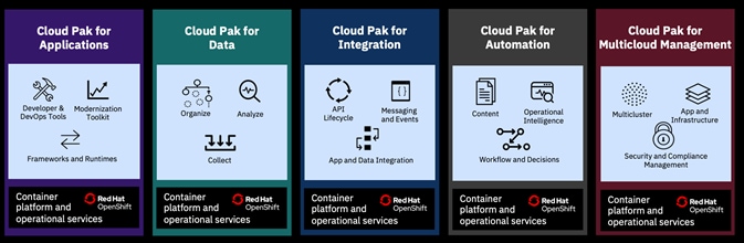
IBM Cloud Pak for Applications
Accelerates the build of cloud-native apps by leveraging built-in developer tools and processes, including support for microservices functions and serverless computing. Customers can quickly build apps on any cloud, at the same time existing IBM middleware clients gain the most straightforward path to modernization. For more information, refer to the following website:
https://www.ibm.com/cloud/cloud-pak-for-applications
IBM Cloud Pak for Data
Unifies and simplifies the collection, organization, and analysis of data. Enterprises can turn data into insights through an integrated cloud-native architecture. IBM Cloud Pak for Data is extensible, easily customized to unique client data and AI landscapes through an integrated catalog of IBM, open-source and third-party microservices add-ons. For more information, refer to the following website:
https://www.ibm.com/products/cloud-pak-for-data
IBM Cloud Pak for Integration
Supports the speed, flexibility, security and scale required for all of your integration and digital transformation initiatives and comes pre-integrated with a set of capabilities including API lifecycle, application, and data integration, messaging, and events, high-speed transfer, and integration security. For more information, refer to the following website:
https://www.ibm.com/cloud/cloud-pak-for-integration
IBM Cloud Pak for Multi-cloud Management
Provides consistent visibility, automation, and governance across a range of hybrid, multi-cloud management capabilities such as event management, infrastructure management, application management, multi-cluster management, edge management, and integration with existing tools and processes. For more information, refer to the following website:
https://www.ibm.com/cloud/cloud-pak-for-management
IBM Cloud Pak for Automation
Orchestrates deployment on your choice of clouds, with low-code tools for business users and real-time performance visibility for business managers. Customers can migrate their automation runtimes without application changes or data migration, and automate at scale without vendor lock-in. For more information, refer to the following website:
https://www.ibm.com/cloud/cloud-pak-for-automation
Accelerate Application Modernization
The IBM Cloud Pak for Applications (ICPA) provides a complete and consistent experience and solution to modernize enterprise applications for cloud-native deployments. Customers can easily modernize their existing applications with IBM’s integrated tools and develop new cloud-native applications faster for deployment on any cloud or on-premises. One of the features included in the Pak is ‘Accelerators for Teams’, a modern microservices-based framework that enables developers, architects and operation teams to work together, faster on end-to-end solutions for the team to build, deploy, and manage the lifecycle of Kubernetes-based applications.
IBM Cloud Pak for Applications support the acceleration of both modernizing existing and developing new cloud native applications as shown in Figure 41. Gradually modernize traditional applications in a cost-effective way that makes sense for your business. Running on OpenShift, IBM Cloud Pak for Applications enables quick building, testing, and deployment microservice-based applications, providing an end-to-end experience to speed developing applications by using predefined built-in developer tools and processes. IBM provides tools to help with the modernization process of applications, including Transformation Advisor (TA). To help convert an application to a cloud-native model, Transformation Advisor scans the code of existing Java applications, collects data, and analyzes the readiness of an application for conversion to a container. Transformation Advisor is included with IBM Cloud Pak for Applications.
Figure 41 IBM Cloud Pak for Applications with VersaStack