Cisco UCS Solution for Microsoft Azure Stack HCI
Available Languages
Bias-Free Language
The documentation set for this product strives to use bias-free language. For the purposes of this documentation set, bias-free is defined as language that does not imply discrimination based on age, disability, gender, racial identity, ethnic identity, sexual orientation, socioeconomic status, and intersectionality. Exceptions may be present in the documentation due to language that is hardcoded in the user interfaces of the product software, language used based on RFP documentation, or language that is used by a referenced third-party product. Learn more about how Cisco is using Inclusive Language.
- US/Canada 800-553-2447
- Worldwide Support Phone Numbers
- All Tools
 Feedback
 Feedback
August 2022

Document Organization
This document is organized into the following chapters:
● Deployment Hardware and Software
● Appendix
| Date |
Change |
| June 30, 2022 |
Original publication |
| August 30, 2022 |
● Cisco UCS Firmware updated from 4.1(3h) to 4.1(3i)
● Drivers updated from release 1.22.05(1) to release 1.2208(1). Release 1.2208(1). Driver package is AzSHCI-21H2_UCS_M5_Drivers_2208.1.zip
● Driver updated in driver package AzSHCI-21H2_UCS_M5_Drivers_2208.1.zip
● QLogic QL45412H Ethernet Adapter: QEND 8.58.15.0
● Added procedure for updating UCS firmware
● Added procedure for updating drivers
|
About the Cisco Validated Design Program
The Cisco Validated Design (CVD) program consists of systems and solutions designed, tested, and documented to facilitate faster, more reliable, and more predictable customer deployments. For more information, go to: http://www.cisco.com/go/designzone.
Cisco Validated Designs (CVDs) include systems and solutions that are designed, tested, and documented to facilitate and improve customer deployments. These designs incorporate a wide range of technologies and products into a portfolio of solutions that have been developed to address the business needs of customers. Cisco UCS® Solution for Microsoft Azure HCI offers highly available and scalable software-defined hyperconverged solution that is enable by the purpose-built Azure Stack HCI 21H2 Operating System. The Azure Stack HCI 21H2 Operating System is an Azure hybrid cloud designed hyperconverged solution that is based on Microsoft Windows Server 2022 and includes Storage Spaces Direct t, Windows Failover Clustering, and Hyper-V.
Azure Stack is a family of three solutions that include Azure Stack HCI, Azure Stack Hub, and Azure Stack Edge. Azure Stack HCI is focused on the following use cases:
● Datacenter consolidation
● Virtual desktop Infrastructure
● Business critical infrastructure
● Storage cost reduction
● High availability and disaster recovery
● Enterprise application virtualization
● Azure Kubernetes Services
● Remote branch office system
● Arc enabled services
This document describes the architecture, topology, and deployment of Azure Stack HCI on Cisco UCS C240M5L and Cisco UCS C240 M5SX servers with Cisco UCS 6332 Fabric Interconnects. Following the deployment guidance as specified in this document will result in a solution that adheres to both Cisco and Microsoft best practices.
This chapter contains the following:
● Audience
Software defined data center solutions enable IT organizations to optimize resource efficiency and improve service delivery. It combines compute virtualization, software defined storage, and virtualized networking that meets or exceeds high availability, performance, and security requirements of the most demanding deployments. The solution uses a shared-nothing architecture and takes advantage of the compute, storage, and network resources that are available within individual server. The servers are connected with external switching fabric that is provides reliable high throughput and low latency.
The audience of this document includes, but is not limited to, sales engineers, field consultants, professional services, IT managers, partner engineers, and customers who want to take advantage of an infrastructure that is built to deliver IT efficiency and enable IT innovation.
This overview and step-by-step deployment document is intended to describe in detail the procedure used to deploy the Azure Stack HCI solution on a Cisco UCS C240M4L and Cisco UCS C240 M5SX rack server with the QLogic FastlinQ 45000 NIC and connected to Cisco UCS 6332 Fabric Interconnects. The procedure in this document should be used for deploying and evaluating this solution in a lab environment prior to deploying the solution in production. The deployment details described in this document need to be implemented as described unless stated otherwise.
This document will be periodically updated with new contents. The contents will include procedures for deploying additional capabilities as well as qualified Cisco UCS firmware and drivers that must be used for deploying this solution.
This chapter contains the following:
● Cisco UCS C240M5L Rack Server
● Cisco UCS 6332 Fabric Interconnect
The Cisco UCS C240 M5 and Cisco UCS C240 M5SX Rack Servers are a 2-socket, 2-Rack-Unit (2RU) rack server offering industry-leading performance and expandability. It supports a wide range of storage and I/O-intensive infrastructure workloads, from big data and analytics to collaboration. Cisco UCS C-Series Rack Servers can be deployed as standalone servers or as part of a Cisco Unified Computing System™ (Cisco UCS) managed environment to take advantage of Cisco’s standards-based unified computing innovations that help reduce customers’ Total Cost of Ownership (TCO) and increase their business agility.
In response to ever-increasing computing and data-intensive real-time workloads, the enterprise-class Cisco UCS C240 M5 and Cisco UCS C240 M5SX server extends the capabilities of the Cisco UCS portfolio in a 2RU form factor. It incorporates the Intel® Xeon® Scalable processors.
Non-Volatile Memory Express (NVMe) PCI Express (PCIe) Solid-State Disks (SSDs) compared to the previous generation of servers. These improvements deliver significant performance and efficiency gains that will improve your application performance. The Cisco UCS C240 M5 delivers outstanding levels of storage expandability with exceptional performance, with:
● The latest second-generation Intel Xeon Scalable CPUs, with up to 28 cores per socket
● Supports the first-generation Intel Xeon Scalable CPU, with up to 28 cores per socket
● Up to 24 DDR4 DIMMs for improved performance including higher density DDR4 DIMMs
● 2 to 4 NVMe PCIe SSDs
● 12 Large-Form-Factor (LFF) 3.5-inch drives plus 2 rear hot-swappable SFF drives
● Support for 12-Gbps SAS modular RAID controller in a dedicated slot, leaving the remaining PCIe Generation 3.0 slots available for other expansion cards
● Dual embedded Intel x550 10GBASE-T LAN-On-Motherboard (LOM) ports
● Modular M.2 or Secure Digital (SD) cards that can be used for boot
Table 1. Item and Specification Details
| Item |
Specifications |
| Form factor |
2RU rack server |
| Processors |
Intel® Xeon® Scalable processors (1 or 2) or second-generation Intel Xeon Scalable processors |
| Memory |
24 DDR4 DIMM slots: 8, 16, 32, 64, and 128 GB and up to 2666 MHz Support for the Intel Optane DC Persistent Memory (128G, 256G, 512G) |
| PCIe expansion |
6 PCIe 3.0 slots plus 1 dedicated 12-Gbps RAID controller slot and 1 dedicated mLOM slot |
| Storage controller |
Internal controllers: Cisco 12-Gbps Modular SAS Host Bus Adapter (HBA) |
| Internal storage |
Backplane options:
● Up to 26 x 2.5-inch SAS and SATA HDDs and SSDs and up to 4 NVMe PCIe drives
● Up to 10 x 2.5-inch NVMe PCIe and 16 SAS and SATA HDDs and SSDs
● Up to 12 x 3.5-inch SAS and SATA HDDs and SSDs, and 2 rear 2.5-inch HDDs and SSDs and up to 4 NVMe PCIe drives
|
| Embedded Network Interface Cards (NICs) |
Dual 10GBASE-T Intel x550 Ethernet ports |
| mLOM |
Dedicated mLOM slot that can flexibly accommodate 1-, 10-, 25-, 40-, and 100-Gbps adapters |
| Power supplies |
Hot-pluggable, redundant 770W AC, 1050W AC, 1050W DC, and 1600W AC |
| Other storage |
Dual internal Cisco FlexFlash SD cards (32, 64, and 128 GB) for installing an operating system or hypervisor Support for RAID 0 mirroring between SD cards Dedicated Baseboard Management Controller (BMC) MicroSD card (32 GB) for server utilities Dual M.2 SATA SSD or NVMe |
| Management |
Cisco Integrated Management Controller (IMC) |
| Rack options |
Cisco ball-bearing rail kit with optional reversible cable management farm |
| Hardware and software interoperability |
See the Cisco Hardware and Software Interoperability List for a complete listing of supported operating systems and peripheral options. |
Cisco UCS 6332 Fabric Interconnect
Cisco Unified Computing System Overview
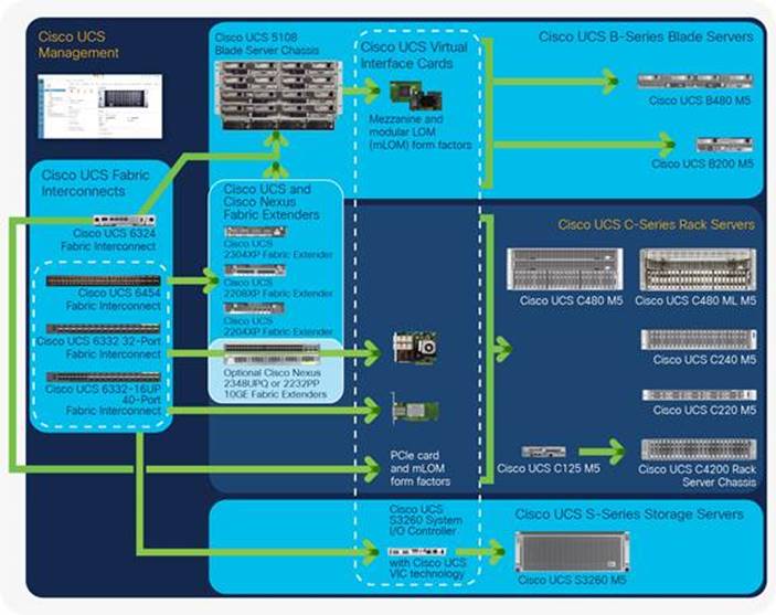
The Cisco Unified Computing System™ (Cisco UCS™) is a next-generation data center platform that unites computing, networking, storage access, and virtualization resources into a cohesive system designed to reduce total cost of ownership (TCO) and increase business agility. The system integrates a low-latency, lossless a 10/25/40 and 100 Gigabit Ethernet unified network fabric with enterprise-class, x86-architecture servers. The system is an integrated, scalable, multichassis platform in which all resources participate in a unified management domain (Figure 1).
Figure 1. The Cisco Unified Computing System Is a Highly Available Cohesive Architecture
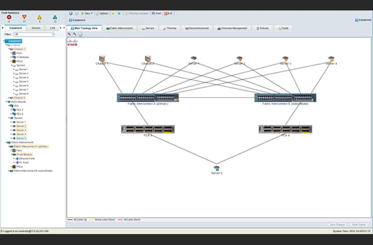
The Cisco UCS 6300 Series hosts and runs Cisco UCS Manager in a highly available configuration, enabling the fabric interconnects to fully manage all Cisco UCS elements. Connectivity to the Cisco UCS 5100 Series blade chassis is maintained through the Cisco UCS 2200 Series or Cisco UCS 2304 Fabric Extenders in each blade chassis. The Cisco UCS 6300 Series interconnects support out-of-band management through a dedicated 10/100/1000-Mbps Ethernet management port as well as in-band management. Cisco UCS Manager typically is deployed in a clustered active-passive configuration on redundant fabric interconnects connected through dual 10/100/1000 Ethernet clustering ports.
Figure 2. The Cisco UCS Manager Graphical User Interface
Cisco UCS 6332UP 32-Port Fabric Interconnect
The Cisco UCS 6332UP 32-Port Fabric Interconnect (Figure 3) is a 1-rack-unit (1RU) 40 Gigabit Ethernet, FCoE and Fibre Channel switch offering up to 2.56 Tbps throughput and up to 32 ports. The switch has 32 fixed 40-Gbps Ethernet and FCoE ports.
Cisco UCS 6332UP 32-Port Fabric Interconnect have ports that can be configured for the breakout feature that supports connectivity between 40 Gigabit Ethernet ports and 10 Gigabit Ethernet ports. This feature provides backward compatibility to existing hardware that supports 10 Gigabit Ethernet. A 40 Gigabit Ethernet port can be used as four 10 Gigabit Ethernet ports. Using a 40 Gigabit Ethernet SFP, these ports on a Cisco UCS 6300 Series Fabric Interconnect can connect to another fabric interconnect that has four 10 Gigabit Ethernet SFPs. The breakout feature can be configured on ports 1 to 12 and ports 15 to 26 on the Cisco UCS 6332UP fabric interconnect.
Figure 3. Cisco UCS 6332UP 32-Port Fabric Interconnect
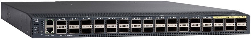
Table 2 lists the features and benefits of the Cisco UCS 6300 Series.
Table 2. Features and Benefits
| Feature |
Benefit |
| Management by Cisco UCS Manager |
Allows all elements connected to the interconnects to participate in a single, highly available management domain |
| Unified fabric |
Decreases TCO by reducing the number of NICs, HBAs, switches, and cables required Transparently encapsulates Fibre Channel packets into Ethernet |
| Fabric extender architecture |
Scales to 20 blade chassis without adding complexity by eliminating the need for dedicated chassis management and blade switches and by reducing the number of cables needed Provides deterministic latency for optimized application performance |
| Performance |
Provides high-speed, low-latency connectivity to the chassis |
| Lossless fabric |
Provides a reliable, robust foundation for unifying LAN and SAN traffic on a single transport |
| Priority flow control (PFC) |
Simplifies management of multiple traffic flows over a single network link. Supports different classes of service, helping enable both lossless and classic Ethernet on the same fabric |
| Systemwide bandwidth management |
Helps enable consistent and coherent quality of service (QoS) throughout the system |
| Cisco Data Center VM FEX technology |
Helps enable a consistent operational model between virtual and physical environments Provides the same level of network visibility for virtualized and nonvirtualized environments Improves diagnostic and troubleshooting capabilities in a virtual environment Simplifies network and security policy enforcement when migrating virtual machines from one host to another |
| Redundant hot-swappable fans and power supplies |
Helps enable high availability in multiple configurations Increases serviceability Provides uninterrupted service during maintenance |
| Front-to-back cooling |
Supports efficient data center hot- and cold-aisle designs |
| SFP+ ports |
Increases flexibility with a range of interconnect solutions, including copper Twinax cable for short runs and fiber for long runs Consumes less power per port than traditional solutions. Helps enable cost-effective connections on fabric extenders with Cisco Fabric Extender Transceiver (FET) optics |
| SFP-compatible ports |
Allows fixed ports to be configured to operate in 40/10 Gigabit Ethernet mode with the transceiver options specified for use with SFP-compatible ports |
| Port-based licensing options |
Helps enable a pay-as-you-go model, allowing customers to add capacity as the networking needs of an individual system increase |
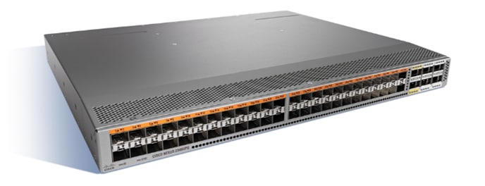
Cisco Nexus 2348UPQ 10GE Fabric Extender (FEX)
The Cisco Nexus 2300 platform with its Cisco® fabric extender architecture provides a highly scalable unified server-access platform across a range of connectivity options such as 1, 10, and 40 Gigabit Ethernet, unified fabric, copper and fiber connectivity, and rack and blade server environments.
Figure 4. Cisco Nexus 2348UPQ 10GE Fabric Extender
The following are the key features and benefits:
● 1/10GBASE-T server connectivity
● Easy migration from 1 Gigabit Ethernet to 10 Gigabit Ethernet or native 40 Gigabit Ethernet
● Effective reuse of structured cabling
● Supports Data Center Bridging (DCB) and LAN and SAN consolidation
● Fibre Channel over Ethernet (FCoE) support up to 30m with Category 6a and 7 cables
● Simplified Operations
● Single point of management, software upgrade, and policy enforcement
● Plug-and-play device
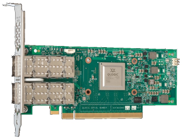
The QLogic QL45412HLCU-CI dual-port Intelligent Ethernet Adapter leverages QLogic’s seventh-generation technology to deliver true 40Gbps Ethernet performance. Optimized for use across enterprises, managed service providers, and large public and scalable private cloud deployments, the QL45412HLCU-CI enables organizations to achieve new levels of performance in physical, virtual, and cloud environments.
The QL45412HLCU-CI 40GbE Adapter delivers advanced features, including:
● Cutting-edge server virtualization technologies—single-root I/O virtualization (SR-IOV) and NIC partitioning (NPAR)
● Network virtualization—offloads for VXLAN, GENEVE, and NVGRE
● Multiple, concurrent RDMA technologies—RDMA over Converged Ethernet (RoCE), RoCEv2, iSCSI Extensions for RDMA (iSER), and is extensible to support iWARP
Figure 5. QLogic FastLinQ QL454412H
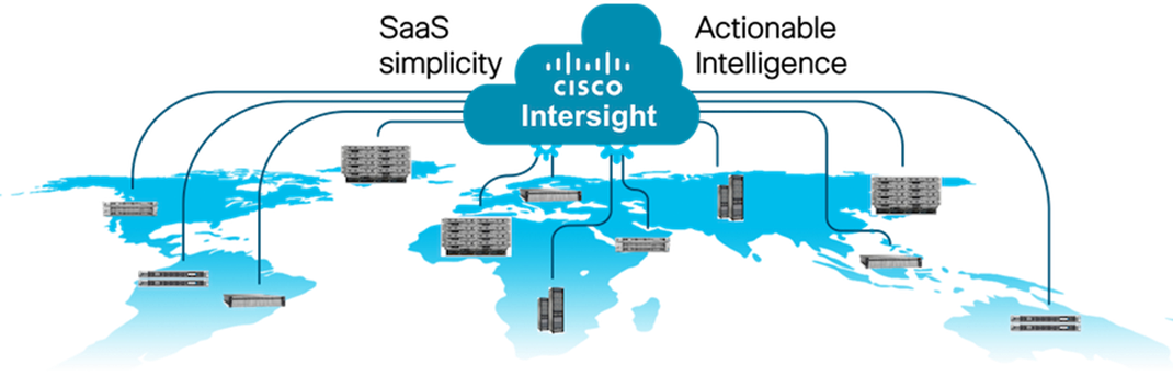
Cisco Intersight is Cisco’s systems management platform that delivers intuitive computing through cloud-powered intelligence. This platform offers a more intelligent level of management that enables IT organizations to analyze, simplify, and automate their environments in ways that were not possible with prior generations of tools. This capability empowers organizations to achieve significant savings in Total Cost of Ownership (TCO) and to deliver applications faster in support of new business initiatives. The advantages of the model-based management of the Cisco UCS® platform plus Cisco Intersight are extended to Cisco UCS servers and Cisco HyperFlex™, including Cisco HyperFlex Edge systems. Cisco HyperFlex Edge is optimized for remote sites, branch offices, and edge environments.
Endpoints supported by Cisco Intersight use model-based management to provision servers and associated storage and fabric automatically, regardless of form factor. Cisco Intersight works in conjunction with Cisco UCS Manager and the Cisco® Integrated Management Controller (IMC). By simply associating a model-based configuration with a resource through server profiles, your IT staff can consistently align policy, server personality, and workloads. These policies can be created once and used by IT staff with minimal effort to deploy servers. The result is improved productivity and compliance and lower risk of failures due to inconsistent configuration.
Cisco Intersight will be integrated with data-center and hybrid-cloud platforms and services to securely deploy and manage infrastructure resources across data-center and edge environments. In addition, Cisco provides integrations to third-party operations tools, starting with ServiceNow, to allow customers to use their existing solutions more effectively.
Cisco Intersight offers flexible deployment either as Software as a Service (SaaS) on Intersight.com or running on your premises with the Cisco Intersight virtual appliance. The virtual appliance provides users with the benefits of Cisco Intersight while allowing more flexibility for those with additional data locality and security requirements.
Cisco Intersight Features and Benefits
Table 3 lists the main features and benefits of Cisco Intersight.
Table 3. Cisco Intersight Features and Benefits
| Feature |
Benefit |
| Unified management |
Simplify Cisco UCS, Cisco HyperFlex, Pure Storage, and Cisco Network Insights management from a single management platform. Increase scale across data centers and remote locations without additional complexity. Use a single dashboard to monitor Cisco UCS and Cisco HyperFlex systems. Cisco UCS Manager, Cisco IMC software, Cisco HyperFlex Connect, and Cisco UCS Director tunneling allow access to element managers that do not have local network access. |
| Configuration, provisioning, and server profiles |
Treat Cisco UCS servers and storage as infrastructure resources that can be allocated and reallocated among application workloads for more dynamic and efficient use of server capacity. Create multiple server profiles with just a few clicks or through the available API, automating the provisioning process. Clone profiles to quickly provision Cisco UCS C-Series Rack Servers in standalone mode. Create, deploy, and manage your Cisco HyperFlex configurations. Help ensure consistency and eliminate configuration drift, maintaining standardization across many systems. |
| Inventory information and status |
Display and report inventory information for Cisco UCS and Cisco HyperFlex systems. Use global search to rapidly identify systems based on names, identifiers, and other information. Use tagging to associate custom attributes with systems. Monitor Cisco UCS and Cisco HyperFlex server alerts and health status across data centers and remote locations. View your Cisco HyperFlex configurations. Track and manage firmware versions across all connected Cisco UCS and Cisco HyperFlex systems. Track and manage software versions and automated patch updates for all claimed Cisco UCS Director software installations. |
| Enhanced support experience |
Get centralized alerts about failure notifications. Automate the generation, forwarding, and analysis of technical support files to the Cisco Technical Assistance Center (TAC) to accelerate the troubleshooting process. |
| Open API |
A RESTful API that supports the OpenAPI Specification (OAS) to provide full programmability and deep integrations systems. The Python and PowerShell SDKs will enable integrations with Ansible, Chef, Puppet, and other DevOps and IT Operations Management (ITOM) tools. ServiceNow integration to provide inventory and alerts to the IT Service Management platform. |
| Seamless integration and upgrades |
Upgrades are available for Cisco UCS, Cisco HyperFlex systems, and Cisco UCS Director software running supported firmware and software versions. Upgrades to Cisco Intersight are delivered automatically without requiring the resources of traditional management tool upgrades and disruption to your operations. |
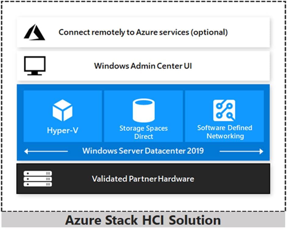
Azure Stack HCI 21H2 is a hyper-converged Windows Server 2022 cluster that uses validated hardware to run virtualized workloads on-premises. You can also optionally connect to Azure services for cloud-based backup, site-recovery, and more. Azure Stack HCI solutions use Microsoft-validated hardware to ensure optimal performance and reliability, and include support for technologies such as NVMe drives, persistent memory, and remote-direct memory access (RDMA) networking.
Azure Stack HCI is a solution that combines several products:
● Hardware from an OEM partner
● Azure Stack HCI OS 21H2
● Windows Admin Center
● Azure services (optional)
Azure Stack HCI is Microsoft’s hyperconverged solution available from a wide range of hardware partners. Consider the following scenarios for a hyperconverged solution to help you determine if Azure Stack HCI is the solution that best suits your needs:
● Refresh aging hardware. Replace older servers and storage infrastructure and run Windows and Linux virtual machines on-premises and at the edge with existing IT skills and tools.
● Consolidate virtualized workloads. Consolidate legacy apps on an efficient, hyperconverged infrastructure. Tap into the same types of cloud efficiencies used to run hyper-scale datacenters such as Microsoft Azure.
● Connect to Azure for hybrid cloud services. Streamline access to cloud management and security services in Azure, including offsite backup, site recovery, cloud-based monitoring, and more.
Hyperconverged Efficiencies
Azure Stack HCI solutions bring together highly virtualized compute, storage, and networking on industry-standard x86 servers and components. Combining resources in the same cluster makes it easier for you to deploy, manage, and scale. Manage with your choice of command-line automation or Windows Admin Center.
Achieve industry-leading virtual machine performance for your server applications with Hyper-V, the foundational hypervisor technology of the Microsoft cloud, and Storage Spaces Direct technology with built-in support for NVMe, persistent memory, and remote-direct memory access (RDMA) networking.
Help keep apps and data secure with shielded virtual machines, network micro segmentation, and native encryption.
Hybrid Cloud Capabilities
You can take advantage of cloud and on-premises working together with a hyperconverged infrastructure platform in public cloud. Your team can start building cloud skills with built-in integration to Azure infrastructure management services:
● Azure Site Recovery for high availability and disaster recovery as a service (DRaaS).
● Azure Monitor, a centralized hub to track what’s happening across your applications, network, and infrastructure – with advanced analytics powered by AI.
● Cloud Witness, to use Azure as the lightweight tie breaker for cluster quorum.
● Azure Backup for offsite data protection and to protect against ransomware.
● Azure Update Management for update assessment and update deployments for Windows VMs running in Azure and on-premises.
● Azure Network Adapter to connect resources on-premises with your VMs in Azure via a point-to-site VPN.
● Sync your file server with the cloud, using Azure File Sync.
Management Tools
Azure Stack HCI uses the same virtualization and software-defined storage and networking software as Azure Stack. However, with Azure Stack HCI you have full admin rights on the cluster and can manage any of its technologies directly:
● Hyper-V
To manage these technologies, you can use the following management tools:
● Windows Admin Center (optional)
● System Center (Optional)
● Other management tools such as Server Manager, and MMC snap-ins (Optional)
● Non-Microsoft tools such as 5Nine Manager (Optional)
If you choose to use System Center to deploy and manage your infrastructure, you'll use System Center Virtual Machine Management (VMM) and System Center Operations Manager. With VMM, you provision and manage the resources needed to create and deploy virtual machines and services to private clouds.
Hyper-V
Hyper-V is Microsoft's hardware virtualization product. It lets you create and run a software version of a computer, called a virtual machine. Each virtual machine acts like a complete computer, running an operating system and programs. When you need computing resources, virtual machines give you more flexibility, help save time and money, and are a more efficient way to use hardware than just running one operating system on physical hardware.
Hyper-V runs each virtual machine in its own isolated space, which means you can run more than one virtual machine on the same hardware at the same time. You might want to do this to avoid problems such as a crash affecting the other workloads, or to give different people, groups or services access to different systems.
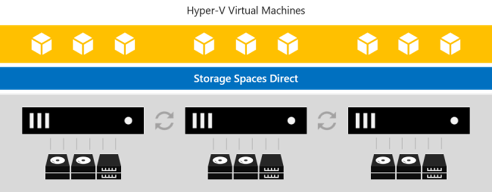
Storage Spaces Direct
Storage Spaces Direct uses industry-standard servers with local-attached drives to create highly available, highly scalable software-defined storage at a fraction of the cost of traditional SAN or NAS arrays. The hyper-converged architecture radically simplifies procurement and deployment, while features such as caching, storage tiers, and erasure coding, together with the latest hardware innovations such as RDMA networking and NVMe drives, deliver unrivaled efficiency and performance.
One cluster for compute and storage. The hyper-converged deployment option runs Hyper-V virtual machines directly on the servers providing the storage, storing their files on the local volumes. This eliminates the need to configure file server access and permissions and reduces hardware costs for small-to-medium business or remote office/branch office deployments.
Storage Spaces Direct is the evolution of Storage Spaces, first introduced in Windows Server 2012. It leverages many of the features you know today in Windows Server, such as Failover Clustering, the Cluster Shared Volume (CSV) file system, Server Message Block (SMB) 3, and of course Storage Spaces. It also introduces new technology, most notably the Software Storage Bus.
Figure 6. Overview of the Storage Spaces Direct Stack
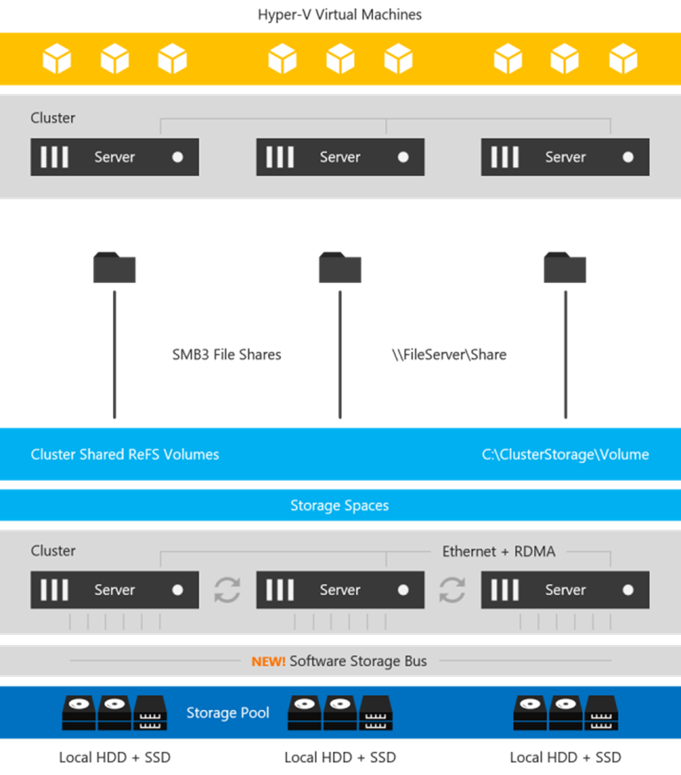
Networking Hardware. Storage Spaces Direct uses SMB3, including SMB Direct and SMB Multichannel, over Ethernet to communicate between servers. We strongly recommend 10+ GbE with remote-direct memory access (RDMA)
Storage Hardware. From 2 to 16 servers with local-attached SATA, SAS, or NVMe drives. Each server must have at least 2 solid-state drives, and at least 4 additional drives. The SATA and SAS devices should be behind a host-bus adapter (HBA) and SAS expander. We strongly recommend the meticulously engineered and extensively validated platforms from our partners (coming soon).
Failover Clustering. The built-in clustering feature of Windows Server is used to connect the servers.
Software Storage Bus. The Software Storage Bus is new in Storage Spaces Direct. It spans the cluster and establishes a software-defined storage fabric whereby all the servers can see all of each other's local drives. You can think of it as replacing costly and restrictive Fibre Channel or Shared SAS cabling.
Storage Bus Layer Cache. The Software Storage Bus dynamically binds the fastest drives present (e.g. SSD) to slower drives (e.g. HDDs) to provide server-side read/write caching that accelerates IO and boosts throughput.
Storage Pool. The collection of drives that form the basis of Storage Spaces is called the storage pool. It is automatically created, and all eligible drives are automatically discovered and added to it. We strongly recommend you use one pool per cluster, with the default settings. Read our Deep Dive into the Storage Pool to learn more.
Storage Spaces. Storage Spaces provides fault tolerance to virtual "disks" using mirroring, erasure coding, or both. You can think of it as distributed, software-defined RAID using the drives in the pool. In Storage Spaces Direct, these virtual disks typically have resiliency to two simultaneous drive or server failures (e.g. 3-way mirroring, with each data copy in a different server) though chassis and rack fault tolerance is also available.
Resilient File System (ReFS). ReFS is the premier filesystem purpose-built for virtualization. It includes dramatic accelerations for .vhdx file operations such as creation, expansion, and checkpoint merging, and built-in checksums to detect and correct bit errors. It also introduces real-time tiers that rotate data between so-called "hot" and "cold" storage tiers in real-time based on usage.
Cluster Shared Volumes. The CSV file system unifies all the ReFS volumes into a single namespace accessible through any server, so that to each server, every volume looks and acts like it's mounted locally.
Failover Clustering
A failover cluster is a group of independent computers that work together to increase the availability and scalability of clustered roles (formerly called clustered applications and services). The clustered servers (called nodes) are connected by physical cables and by software. If one or more of the cluster nodes fail, other nodes begin to provide service (a process known as failover). In addition, the clustered roles are proactively monitored to verify that they are working properly. If they are not working, they are restarted or moved to another node.
Failover clusters also provide Cluster Shared Volume (CSV) functionality that provides a consistent, distributed namespace that clustered roles can use to access shared storage from all nodes. With the Failover Clustering feature, users experience a minimum of disruptions in service.
Failover Clustering has many practical applications, including:
● Highly available or continuously available file share storage for applications such as Microsoft SQL Server and Hyper-V virtual machines
● Highly available clustered roles that run on physical servers or on virtual machines that are installed on servers running Hyper-V
This chapter contains the following subject:
The Cisco solution for Azure Stack HCI architecture most be implemented as described in this document. Cisco provides a specific PID for ordering the configuration. The PID includes all of the required components that comprise the solution. The Azure Stack HCI cluster can be scaled from 4 to 16 servers. The architecture has a data fabric and a management fabric. The servers connect to the data fabric using dual 40Gb connections. This data fabric is provided by the Cisco UCS 6332 Fabric Interconnects provide layer 2 connectivity and carries both storage and infrastructure traffic. The fabric interconnects also run Cisco UCS Manager which is the element manager for all of the Cisco UCS components in this solution. Server management is facilitated though the Fabric Extenders that connect the server management ports to the fabric interconnect. Each server has two management ports that are connected with 1Gbe links. The servers Azure Stack HCI OS 21H2 provides a rich set of software defined services that are core to this solution.
The data center is expected to have infrastructure services such as DNS and Active Directory. WDS (Windows Deployment Service) and DHCP are also recommended to expedite deployments. These services must be accessible through the ToR (Top of Rack) or EoR (End of Row) network switches that connect the Cisco UCS Fabric Interconnects that are part of the Cisco solution for Azure Stack HCI to the datacenter infrastructure.
Figure 7. Physical Topology
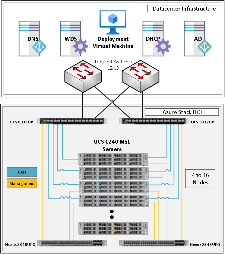
The following are the components that comprise the Azure Stack HCI:
● Cisco UCS 6332UP Fabric Interconnects
● Cisco UCS C240M5L Server
● Cisco Nexus 2348UP Fabric Extenders
The Cisco UCS 6332UP Fabric Interconnects carry both data and management network traffic to the Cisco UCS C240M5L servers. The data traffic flows throw 40GbE links to the QLogic QL45412HLCU-CI network interface card in each server. Out of band management traffic is facilitated by a 40GbE connection to each of the two Cisco Nexus 2348UPQ Fabric Extenders. The Cisco Nexus 2348UPQ Fabric Extenders connect the 1GbE LOM ports on the server for communication with the Cisco Integrated Management Controller in each server. The two pairs for UCS 6332UP Fabric Interconnects and Cisco Nexus 2348UPQ Fabric Extenders provide high availability and redundancy for both data and management network traffic.
The ToR (Top of Rack) switches can be any switch that is on the UCS 6332 Fabric Interconnect Hardware Compatibility List for the version of UCS firmware that is running on the Fabric Interconnects. The ToR switch provides layer 2 and layer 3 connectivity to the fabric interconnects. The connections between the ToR switches and the fabric interconnects should use the maximum link speeds supported by the boarder switch ports and the fabric interconnect ports. It’s recommended to use 40GbE link speeds for connecting the UCS 6332 Fabric Interconnect. The ToR switches should include a security focused configuration that is standardized within the datacenter network.
The Appendix of this document has sample configurations that can be implemented in the ToR switch. These sample configurations include vPC, SVI, HSRP, and DHCP Relay.
It is expected that the datacenter has a secure OoB (Out of Band) management network that is used to managed network devices in the datacenter. Cisco UCS fabric interconnects are directly connected to the out of band management switches and a disjoint layer-2 configuration is used to keep the management network path separate from the data network path. The OoB network needs to have internet access in order for Cisco Intersight to be able to access the fabric interconnects.
Connect Fabric Interconnects to ToR Switches
The uplinks between the fabric interconnects and ToR switches carry north-south bound traffic to and from the tenant virtual machines as well as the host servers. In addition, these uplinks may also carry a portion of the east-west tenant virtual machine traffic. The uplinks need to have sufficient bandwidth to support both traffic types. Make sure to avoid configuring more than 2 fabric interconnects ports in breakout mode. Configuring more than two fabric interconnects ports in breakout mode will impact RDMA traffic that runs through the fabric interconnects.
Note: Cisco recommends using 40GbE uplinks that do not require the use configuring an uplink port as breakout port.
Breakout ports can be used in configuration with 4 to 6 Azure Stack HCI hosts. Make sure to avoid configuring more than 2 fabric interconnects ports in breakout mode. Configuring more than two fabric interconnects ports in breakout mode will impact RDMA traffic that runs through the fabric interconnects.
The following table describes recommendations for the number of uplink ports to configure on each fabric interconnect.
| Number of Azure Stack HCI Host servers |
Number of 40GbE Uplinks per Fabric Interconnect |
Number of Breakout ports with all 4 x 10GbE connections to ToR Switch |
| 4-6 |
2 |
2 |
| 7-11 |
4 |
n/a |
| 12-16 |
6 |
n/a |
Note: Breakout ports are should only be used when 40GbE ports are not available on the ToR switches. Breakout ports are an alternative to 40GbE ports for 4 to 6 node deployments.
Note: Only ports 17 to 26 can be configured in breakout mode for an Azure Stack HCI deployment because Azure Stack HCI hosts are expected to be connected to ports 1 to 16.
The fabric interconnects are configured for MTU size of 9216. The ToR switch MTU size of 9216 must also be configured for the ports that connect the fabric interconnects. The MTU size for the packets sent on the network will be controlled by the endpoints.
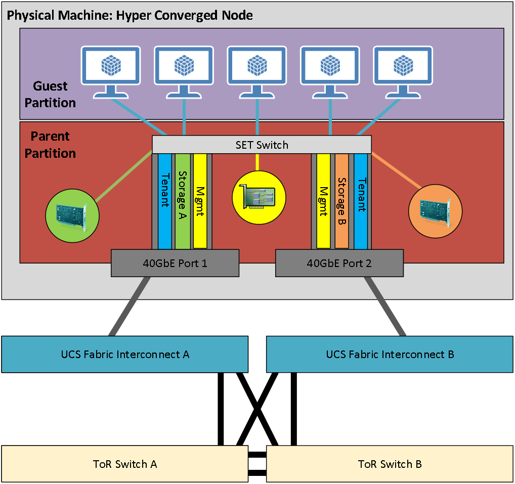
The logical topology is comprised of the following:
● Tenant Network
The Tenant network is a VLAN trunk that carries one or more VLANs that provide access to the tenant virtual machines. Each VLAN is provisioned in the ToR switch, Fabric interconnect, and SET switch running on the physical server. Each tenant VLAN is expected have an IP subnet assigned to it.
● Management Network
The management network is a VLAN that carries network traffic to the parent partition. This network is used to access the host operating system. The connectivity to the management network is provided by the management (Mgmt) vNIC in the parent partition. Fault tolerance for the management vNIC is provided by the SET switch. A bandwidth limit can be assigned to the management, as necessary.
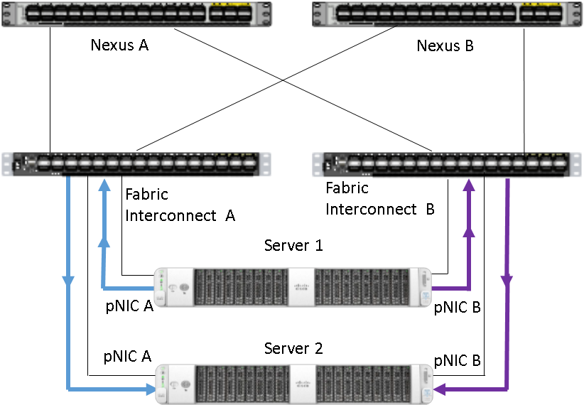
● Storage Network
The storage network carries RoCEv2 RDMA network traffic that is used for Storage Spaces Direct storage replication, and Live Migration network traffic. This network is also used for cluster management communication. The storage network has a Storage A and Storage B segment, each with its own IP subnet. This design keeps the east-west RDMA isolated to the fabric interconnects and avoids the need for the ToR switches to be configured for supporting RoCEv2 traffic.
Figure 8 illustrates the east-west RDMA traffic isolation.
Figure 8. East-West RDMA Traffic Isolation
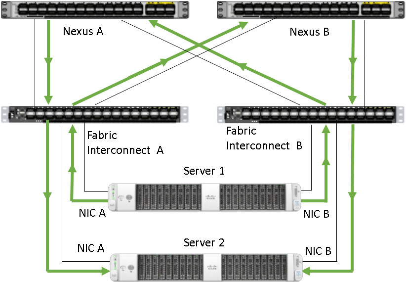
● SET Switch
This is a virtual switch with embedded teaming capabilities. The SET Switch provides teaming capabilities for network traffic that does not use SMB-Multichannel. SMB Direct (RDMA) traffic uses SMB-Multichannel for link aggregation and redundancy instead of the teaming feature in the SET switch.
MAC addresses for virtual NICs are randomly assigned to one on the physical NIC ports on the host. This MAC address assignment can be moved from one physical NIC to another at any time by the SET switch. This behavior provides load balancing and fault tolerance. A consequence of this behavior is that some of the east-west network traffic that is not storage SMB Direct (RDMA) traffic will transverse the ToR switches. An example of this is when virtual machine A with a virtual NIC MAC address assigned to physical NIC A communicates with virtual machine B that has virtual NIC MAC assigned to physical NIC B. Figure 9 illustrates this behavior.
Figure 9. MAX Address Assignment
● Guest Partition
The tenant virtual machines run in the guest partition on the Hyper-V host. Each virtual machine runs in isolation from others and does not have direct access to physical hardware in the host. Network connectivity is provided to the tenant virtual machine by connecting synthetic NIC in the virtual machine to the SET switch on the host.
● Parent Partition
The parent partition is the host operating system that runs the virtualization management stack and has access to the physical server hardware. The parent partition has one management vNIC and two storage vNICs. An optional dedicated vNIC for backup operations can be added as needed.
Figure 10. Parent Partition
Deployment Hardware and Software
This chapter contains the following:
● Customer Support Requirements
Firmware and drivers can be found on the Cisco download portal for Azure Stack HCI. These components are as these components will be periodically updated. Please sign up for notification at this download portal to receive notifications emails when updates are available.
The Cisco platform for Microsoft Azure Stack HCI firmware download portal can be accessed by selecting Azure Stack HCI Update Software from the Cisco UCS C-Series Rack-Mount UCS-Managed Server Software Download page. Also, it can be set up to notify you about the availability of the new firmware. Cisco highly recommends that you sign up for these notifications.
The following software components hosted on Microsoft Azure Stack HCI firmware download portal are required for the firmware upgrade procedure:
| Component |
Description |
| ucs-6300-k9-bundle-infra.<version number>.A.bin |
UCS Infrastructure Firmware Bundle |
| ucs-k9-bundle-c-series.<version number>.C.bin |
UCS C-Series Server Firmware Bundle |
| AzSHCI-21H2_UCS_M5_Drivers_ <version number>.zip |
Azure Stack HCI 21H2 drivers for UCS C240M5 servers |
The following tables list the individual component version that are part of the respective firmware bundles and driver package:
| Cisco UCS Fabric Interconnect and Fabric Extender |
||
| Component |
Infrastructure Bundle |
Firmware Version |
| Cisco UCS 6300 Fabric Interconnect |
4.1(3i) |
5.0(3)N2(4.13h) |
| Cisco UCS Manager |
4.1(3i) |
4.1.3i |
| Cisco Nexus 2348UPQ Fabric Extender |
4.1(3i) |
5.0(3)N2(4.13h) |
| Cisco UCS C240M5SX Servers |
|
||
| Component |
C-Series Bundle |
Firmware Version |
Driver Version |
| BIOS |
4.1(3i) |
C240M5.4.1. 3l.0.0602221625 |
|
| CIMC (BMC) |
4.1(3i) |
4.1.3h |
|
| Board Controller |
4.1(3i) |
63 |
|
| SAS HBA |
4.1(3h) |
11.00.05.02 |
2.61.19.80 (inbox) |
| QLogic QL45412H Ethernet Adapter |
4.1(3i) |
08.04.23.04.06 |
EVBD 8.58.18.0 |
| QEND 8.58.15.0 |
|||
| MegaSR1 |
4.1(3h) |
|
18.03.2021.0929 |
| Boot SSD (UCS-M2-960GB) |
4.1(3i) |
D0MH077 |
10.0.17763.1 (inbox) |
| Western Digital NVMe Cache SSD (WUS4C6416DSP3X3) |
4.1(3i)) |
R2210002 |
10.0.20348.1 (inbox) |
| Micron 5300 SATA SSD |
4.1(3i) |
D3MC000 |
10.0.17763.1 (inbox) |
| Cisco UCS C240M5L Servers |
|||
| Component |
C-Series Bundle |
Firmware Version |
Driver Version |
| BIOS |
4.1(3i) |
C240M5.4.1. 3l.0.0602221625 |
|
| CIMC (BMC) |
4.1(3i) |
4.1.3h |
|
| Board Controller |
4.1(3i) |
63 |
|
| SAS HBA |
4.1(3i) |
11.00.05.02 |
2.61.19.80 (inbox) |
| QLogic QL45412H Ethernet Adapter |
4.1(3h) |
08.04.23.04.06 |
EVBD 8.58.18.0 |
| QEND 8.58.15.0 |
|||
| MegaSR1 |
4.1(3i) |
|
18.03.2021.0929 |
| Boot SSD (UCS-M2-960GB) |
4.1(3i) |
D0MH077 |
10.0.17763.1 (inbox) |
| Western Digital NVMe Cache SSD (WUS4C6416DSP3X3) |
4.1(3i)) |
R2210002 |
10.0.20348.1 (inbox) |
| Western Digital HDD |
4.1(3i) |
A3Z4 |
10.0.17763.1 (inbox) |
| Host Operating System |
|
| Host OS Version |
Azure Stack HCI OS 21H2 with current updates |
Figure 11 illustrates the physical topology of an Azure Stack HCI deployment on Cisco UCS C240 M5 servers with Cisco UCS 6332 Fabric interconnects. The cabling map can be found in the Appendix of this document.
Figure 11. Physical Infrastructure
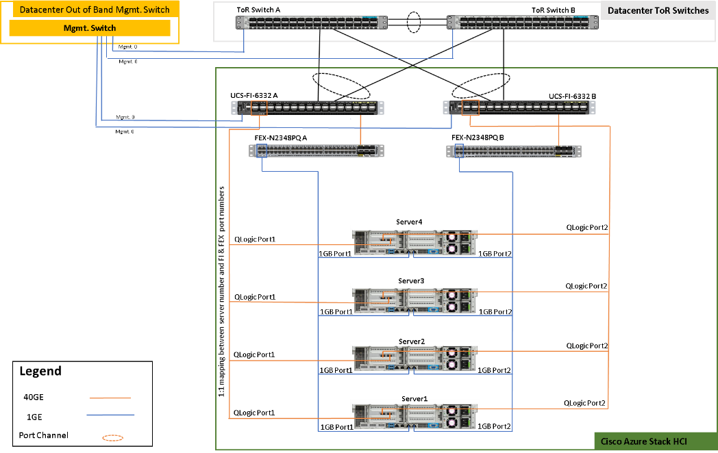
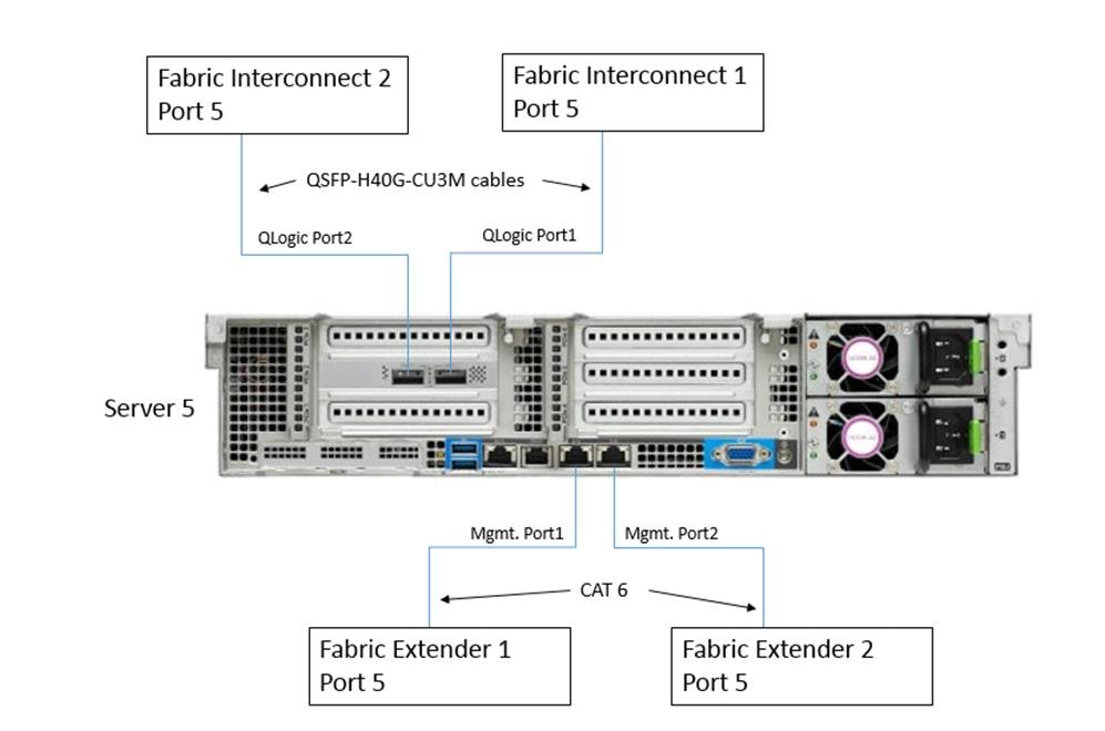
Figure 12 illustrates the data ports and management ports on the back of each server. In this example Server 5 has its two 40Gb data ports connected to port 4 on Fabric Interconnect 1 and 2. The out-of-band management ports are connected to port 5 fabric extender of each fabric extender.
Figure 12. Data Ports and Management Ports
The following is the checklist for the deployment:
● ToR switch must be on the Cisco FI 6332 HCL
● ToR switch must implement L2 and L3 configuration for transporting northbound host and tenant traffic
● No more than 2 ports can be configured in breakout mode on each fabric interconnect
● Out of Band management switch must be provided for connecting the fabric interconnects
● 3 IP addresses are required on the Out of Band Management Network for UCS Manager
● 1 IP address must be provided for each host (server) on the Out of Band Management Network
● VLANs
◦ 1 Management
◦ 2 Storage
◦ 1 or more tenant
● IP subnets and addresses for all endpoints for the above VLANs
● Storage VLANs and Storage subnets do not need to be configured on the ToR switches
● Host operating system must have access to Azure
● Datacenter infrastructure that includes Active Directory Services, DNS, and NTP
● Cluster Quorum Witness
◦ Can be Files Share or Cloud Witness
◦ Required for Cluster with fewer than 5 cluster nodes
● Recommended for clusters with 5 or greater n number of nodes
● Deployment host must be provided with access to the Out-of-Band Managed network and host management network
◦ See the Deployment Host Software configuration in the Appendix
● Deployment host must be running Windows Server 2019 or Windows Server 2022 and be domain joined to the same domain as the Azure Stack HCI hosts
● Account used to deploy Azure Stack HCI must have administrative rights on the Azure stack hosts and permissions to join the domain, add cluster securing principle to the domain, update the DNS A records for the computer joining the domain and Cluster Aware Updating services, and store Bitlocker keys in the domain.
● Azure Account for registering Azure Stack HCI
● Download Azure Stack HCI OS 21H2 from Microsoft download site
● Download Cisco Drivers for Azure Stack HCI 21H2 deployment from Cisco download portal (link to be added)
● Download UCS Manager configuration script for Azure Stack HCI 21H1 deployments from Cisco download portal (link to be added)
● Recommended Items
◦ Windows Deployment Service for PXE boot OS installation (Can be running on deployment host)
◦ DHCP server with scope for management subnet to support PXE booting. Scope is temporary and only needed dur-ing PXE boot installation phase. (Can be running on deployment host)
Bill of Materials
This solution must be purchased using the Cisco UCS product ID UCS-MAH-B00R00. This product ID includes all of the required hardware to build the solution as well as the Cisco Solution Support for this solution. A sample BoM is documented in the Cisco UCS for Microsoft Azure Stack HCI Datasheet at the following links:
The solution must adhere to Cisco Guidance for deploying Azure Stack HCI on Cisco UCS product ID UCS-MAH-B00R00.
Firmware and driver version must match the versions specified in this document. This document will be update periodically with more current firmware and driver versions. Customers are required to update their systems to the latest firmware and driver version within 60 days of the requirements update for this Azure Stack HCI solution.
Note: Current firmware and drivers can be downloaded from the Cisco download portal for Azure Stack HCI. The link to the download portal is in the Firmware and Drivers section.
Note: You must obtain an Azure Stack HCI support contract from Microsoft. The following is an example of this type of support contract:
● Unified Support for Enterprise
● Premier Support for Enterprise
For support option details, go to: Get support for Azure Stack HCI - Azure Stack HCI | Microsoft Docs
This chapter contains the following subjects:
● Configure Cisco UCS 6332 Fabric Interconnects for Azure Stack HCI
● Launch Cisco UCS Manager Configuration Automation PowerShell Script
● Acknowledge Primary Fabric Interconnect Reboot
● Configure Fabric Interconnect Ports
● Launch Server KVM Instance to Install the Operating System
● Initial Host Network Configuration
● Configure Bitlocker for System Volume
● Configure Network Components
● Prepare Server for Storage Spaces Direct
● Configure Windows Failover Cluster
● Configure Storage Spaces Direct
Configure Cisco UCS 6332 Fabric Interconnects for Azure Stack HCI
Initial Configuration of the Cisco UCS 6332 Fabric Interconnect
The fabric interconnects need basic configuration information in order to management communication on an IP network. The initial configuration requires connecting a serial cable to the serial console port on each Fabric Interconnect. These steps provide details for initial setup of the Cisco UCS 6332 fabric Interconnects.
Procedure 1. Configure Cisco UCS Fabric Interconnect A
Step 1. Connect to the serial console port on the first Cisco UCS 6332 fabric interconnect.
Step 2. At the prompt to enter the configuration method, enter console to continue.
Step 3. If asked to either do a new setup or restore from backup, enter setup to continue.
Step 4. Enter y to continue to set up a new fabric interconnect.
Step 5. Enter y to enforce strong passwords.
Step 6. Enter the strong password for the admin user.
Step 7. Enter the same password again to confirm the password for the admin user.
Step 8. When asked if this fabric interconnect is part of a cluster, answer y to continue.
Step 9. Enter A for the switch fabric.
Step 10. Enter the cluster name for the system name.
Step 11. Enter the Mgmt0 IPv4 address.
Step 12. Enter the Mgmt0 IPv4 netmask.
Step 13. Enter the IPv4 address of the default gateway.
Step 14. Enter the virtual cluster IPv4 address.
Step 15. To configure DNS, answer y. This is required for connecting to Cisco Intersight.
Step 16. Enter the DNS IPv4 address.
Step 17. Answer y to set up the default domain name. This is required for connecting to Cisco Intersight.
Step 18. Enter the default domain name.
Step 19. Review the settings that were printed to the console, and if they are correct, answer yes to save the configuration.
Step 20. Wait for the login prompt to make sure the configuration has been saved.
Procedure 2. Configure Cisco UCS Fabric Interconnect B
Step 1. Connect to the serial console port on the second Cisco UCS 6332 fabric interconnect.
Step 2. When prompted to enter the configuration method, enter console to continue.
Step 3. The installer detects the presence of the partner fabric interconnect and adds this fabric interconnect to the cluster. Enter y to continue the installation.
Step 4. Enter the admin password for the first fabric interconnect.
Step 5. Enter the Mgmt0 IPv4 address for the Fabric Interconnect B.
Step 6. Answer yes to save the configuration.
Step 7. Wait for the login prompt to confirm that the configuration has been saved.
Procedure 3. Communications Services Hardening
Note: These steps provide configuration details for communications services in Cisco UCS Manager server. This procedure disables HTTP, Telnet, CIM XML, and SNPM access to Cisco UCS Manager. HTTPS and SSH access remain enabled.
Step 1. Log into Cisco USC Manager using a supported web browser.
Step 2. Select the Admin icon at in the left window.
Step 3. Select All > Communications Management > Communications Services.
Step 4. In the right pane, set HTTP Admin State to Disabled.
Step 5. Set Telnet Admin State to Disabled
Step 6. Set CIM XML Admin State to Disabled
Step 7. Set SNMP Admin State to Disabled
Step 8. Click Save Changes.
Note: The web browser session to Cisco UCS Manager will be disconnected when this configuration change is made. Please restart the web browser session to Cisco UCS Manager.
Procedure 4. Synchronize Cisco UCS to NTP
Note: These steps provide details for synchronizing the Cisco UCS environment to the NTP server.
Step 1. Log back into Cisco USC Manager using a URL that starts with https://.
Step 2. Select the Admin tab at the top of the left window.
Step 3. Select All > Time Zone Management.
Step 4. Right-click Timezone.
Step 5. In the right pane, select the appropriate timezone in the Time Zone drop-down menu.
Step 6. Click Add NTP Server.
Step 7. Input the NTP server IP and click OK.
Step 8. Click Save Changes and then click OK.
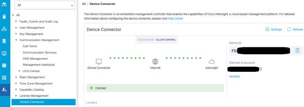
Procedure 5. Cisco Intersight Device Claim
Step 1. Select the Admin icon at in the left window.
Step 2. Select All > Device Connector.
Step 3. Copy the Device ID and Claim Code.
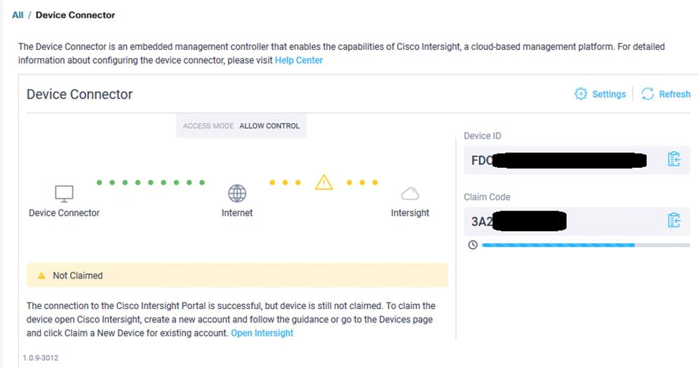
Step 4. Create a Cisco Intersight account—go to https://intersight.com/ to create your Intersight account. You must have a valid Cisco ID to create a Cisco Intersight account. If you do not have a Cisco ID, create one here.
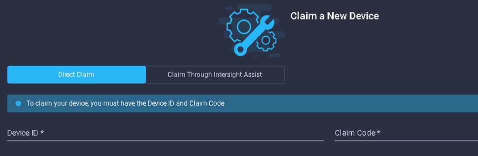
Step 5. To claim the devices bring focus to Devices in the left pane and click Claim a New Device and complete the following steps to claim one or more devices to be managed by Cisco Intersight:
Step 6. In Cisco Intersight, navigate to ADMIN > Targets > Claim Target.
The Select Target Type window is displayed.
Step 7. In the filter column, select Compute / Fabric and select Cisco UCS Domain (UCSM Managed), and then click Start.
Note: Do not select the Cisco UCS Domain (Intersight Managed) target.
Step 8. Enter the Device ID and Claim Code obtained from Cisco UCS Manager.
Step 9. Click Claim.
The Cisco UCS Domain (UCSM Managed) instance will be added to the Intersight Managed devices.
Step 10. Switch back to Cisco UCS Manager to confirm that the device is claimed. Click Refresh to update the status.
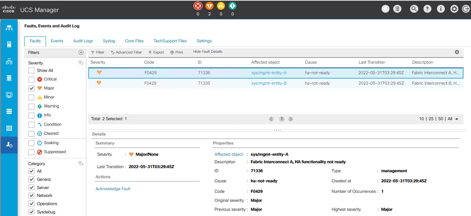
Procedure 6. Review Cisco UCS Manager Events
Note: Review the Cisco UCS Manager events that are reported in the top status bar. At this point it is expected to have two major events reported that indicated that hi availability is not ready for Fabric Interconnect A and Fabric Interconnect B. These events will clear when one or more servers are discovered during a procedure later in this guide.
Cisco UCS Manager Configuration Automation PowerShell Script
See the Deployment Host requirements and configuration for preparing the deployment host. You must download and extract the Cisco UCS Manager configuration package zip file on the deployment host. Cisco UCS Manager configuration package zip file includes a PowerShell script that automates the majority of the Cisco UCS Manager configuration. This script must be run from the deployment host. Manual steps for implementing the Cisco UCS Manager configuration are provided in the Appendix.
Procedure 1. Run the Cisco UCS Manager Configuration Automation PowerShell Script
Step 1. Download the Cisco UCS Manager configuration package zip file UcsmConfig-AzSHCI_<version number>.zip to a directory on the deployment host. (Example target directory: C:\Deploy\Cisco\AzS-HCI)
Step 2. Run the following command in a PowerShell window to unblock the zip file.
Get-ChildItem -path C:\Deploy\Cisco\AzS-HCI -recurse | unblock-file
Step 3. Extract the contents of the Cisco UCS Manager Configuration zip file UcsmConfig-AzSHCI_<version number>.zip.
Step 4. Navigate to the directory that contains UcsmConfig-AzSHCI.ps1
Step 5. Execute the script by running the following command. The command requires the Cisco UCS Manager IP address and account with administrative privileges. The script will prompt for the password to the supplied Cisco UCS Manager account.
.\UcsmConfig-AzSHCI.ps1 -UcsManagerIP [UCS Manager IP Address] -UcsManagerCredential [UCS Manager Account]
Note: The script will take approximately 20 seconds to complete.
Cisco UCS Manager Configuration Automation script configures the following items and VLANs:
|
● Sub Organization
● OoB Management IP Pool
● FEX Discovery Policy
● Flow Control Policy
● Network Control Policy
● PFC-On Mode for Server Ports 1-16
● VLANs
● Storage Profile
● Server Auto Configuration Policy
● Pools
● Server Pool Qualification ● Server Pool Definition ● Two Unique MAC Pools ● One unique UUID pool |
● Policies
● Scrub ● Power Control ● Maintenance ● Local Disk ● Host Firmware Package, including default ● BIOS ● Global Rack Discovery ● Server Pool ● Boot
● Templates
● Two vNICs ● Service Profile
● QoS System Class Update
|
| VLAN Name |
VLAN ID |
| Management |
125 |
| Tenant |
100 |
| Storage-A |
107 |
| Storage-B |
207 |
Note: L3 ToR switch needs the ip helper address configured for the IP subnet assigned to the VLAN that will be used to PXE boot the Azure Stack HCI host during the deployment process.
After the Cisco UCS Manager configuration script completes, verify that the script output did not report any errors or warnings. The script creates a Logs subdirectory that contains the log for the script operations. Review the log to make sure that all operations line items start with the word “Info.” The word “Info” begins a line that completed without failures. Resolve any operations that begin with the work “Warning.” Continue to the next step using the Cisco UCS Manager Web interface.
Acknowledge Primary Fabric Interconnect Reboot
The subordinate fabric interconnect will reboot after updating the QoS System Classes. After the subordinate fabric interconnect reboot completes you must acknowledge the reboot of the primary fabric Interconnect in the Cisco UCS Manager web browser interface.
The bell icon will blink I the top right-hand corner of the Cisco UCS Manager portal, indicating that administrator action is required. The bell icon will blink about 5 to 10 minutes after the subordinate fabric interconnect reboots.

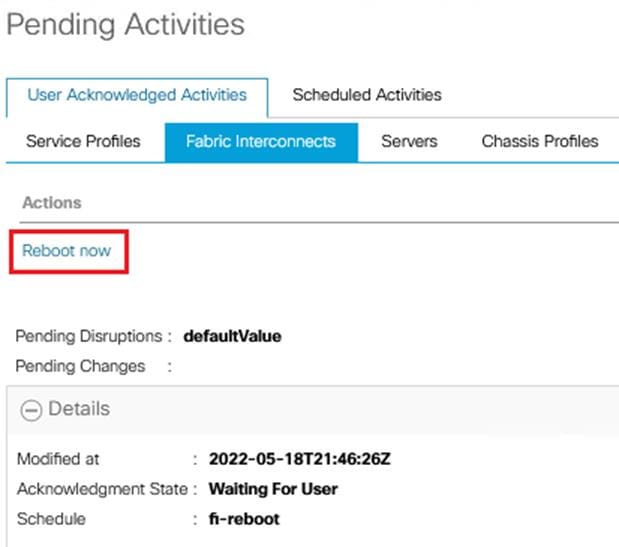
Procedure 1. Acknowledge Primary FI Reboot
Step 1. Click the blinking bell icon to open the Pending Activities popup window.
Step 2. Select the Fabric Interconnect tab.
Step 3. Click Reboot Now in the actions section.
Step 4. Click OK to close the window.
Note: The Cisco UCS Manager portal will terminate when the primary fabric interconnect reboots. Wait a couple of minutes and log back in to the Cisco UCS Manager portal.
After logging backing to Cisco UCS Manager the following events will be logged in the status bar:
● Two major events indicating fabric interconnect high availability is not ready. These events will clear when one or more servers are discovered.
● Two major events for each connected server that indicate link-down port status. These events will clear with the servers are discovered and service profiles are associated.
● One warning event indicating that the Azure Stack server pool is empty. This event will clear when servers are discovered.
● One minor event indicating that AS_OOB_Mgmt IP address pool is empty. This event will clear when the IP address block is assigned to this pool later this configuration guide.
● Two minor events may be logged indicating one or more ports are in licensing grace period. These events will clear when unused server ports are disabled later in this configuration guide.

Configure Fabric Interconnect Ports
Procedure 1. Configure Uplink Ports
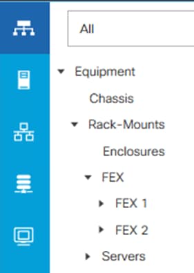
Step 1. Select the Equipment icon at the left of the window.
Step 2. Select Equipment > Fabric Interconnects > Fabric Interconnect A > Fixed Module.
Step 3. Expand the Ethernet Ports object.
Step 4. Select ports 31 and 32 that connect the upstream switches. (See section Connect Fabric Interconnects to ToR Switches for uplink port count requirements)
Step 5. Right-click the ports and select Configure as Uplink Port.
Step 6. A prompt displays asking if this is what you want to do. Click Yes, then click OK to continue.
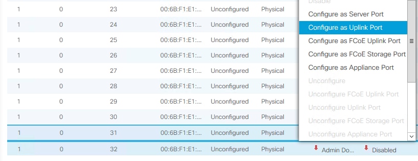
Step 7. Repeat steps 1 - 6 on fabric interconnect B.
Procedure 2. Disable Disconnected Server Ports
Note: The Cisco UCS Manager configuration script will configure ports 1-16 as server ports on each fabric interconnect. The ports that do not have Azure Stack HCI servers connected to them can be disabled. These steps provide the details for disabling server ports that do are not connected to servers.
Step 1. Select the Equipment icon at the left of the window.
Step 2. Select Equipment > Fabric Interconnects > Fabric Interconnect A > Fixed Module.
Step 3. Expand the Ethernet Ports object.
Step 4. Select the ports that are not connected to servers and select Disable.
Step 5. Click Yes to confirm the server ports, and then click OK.
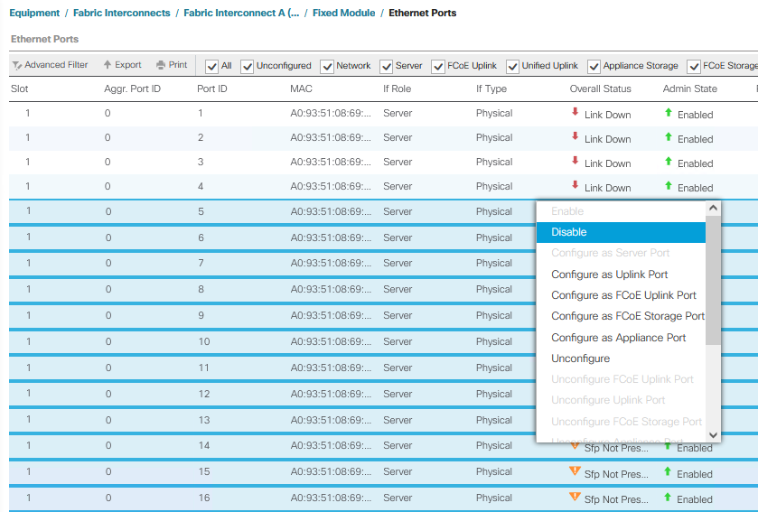
Step 6. Repeat steps 1 - 5 on fabric interconnect B.
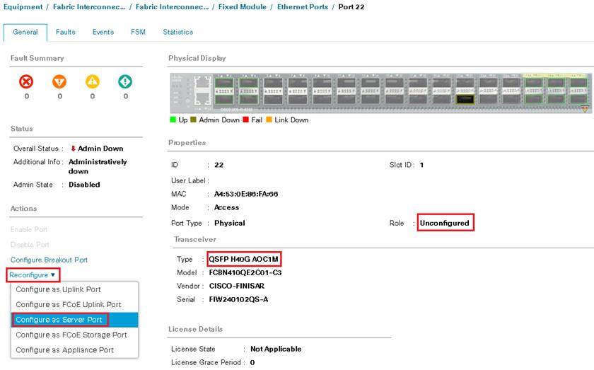
Procedure 3. Configure FEX Connectivity
Note: The following procedure is for use with the FEX model 2348UPQ.
Note: Port 22 on each fabric interconnect has a has a QSFP-H40G-AOC1M cable that connects the FEX (Fabric Extender). This port needs to be configured as a server port. Each Fabric Interconnect will reboot as part of this configuration process.
Step 1. Select the Equipment icon at the left of the window.
Step 2. Select Equipment > Fabric Interconnects > Fabric Interconnect A > Fixed Module.
Step 3. Expand the Ethernet Ports object.
Step 4. Select port 22.
Step 5. Click Reconfigure and select Server Port.
Step 6. Click Yes to confirm configuration and FI reboot.
Step 7. Look for the FEX to become visible in the left pane.
Step 8. Click Acknowledge FEX.
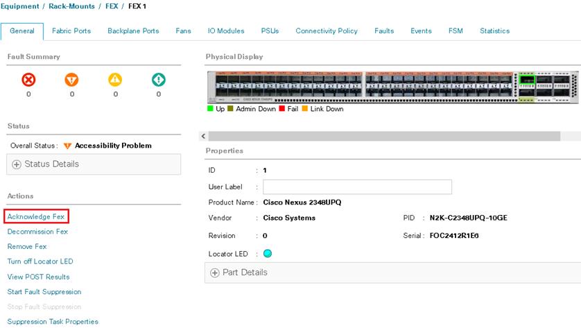
Note: The FEX will be discovered automatically after the connecting ports is configured as server ports and the FEX is acknowledged. It may take about a minute for the accessibility errors to clear.
Step 9. Repeat steps 1 - 8 on Fabric Interconnect B, Port 22.
Note: Fabric Interconnects will reboot after Breakout Port configuration.
Note: Server discovery will begin once the FEXs are discovered. Server discovery will take approximately 20 minutes for discovery to complete. The initial status will be Inoperable, but it will soon change to Discovery.
Note: The administrator can proceed with the following configuration steps while server discovery is running I the background. Server discovery must complete before service profiles can be associated with the servers.
Procedure 4. Add a Block of IP Addresses for KVM Access
Note: These steps provide details for creating a block of KVM IP addresses for server access in the Cisco UCS environment.
Step 1. Log back into Cisco USC Manager
Step 2. Select the LAN icon at the left column of the window.
Step 3. Select Pools > root > Sub-Organizations > Azure-Stack-HCI > IP Pools.
Step 4. Right-click IP Pool AS_OOB_MGMT.
Step 5. Select Create Block of IPv4 Addresses.
Step 6. Enter the starting IP address of the block and number of IP addresses needed as well as the subnet mask and gateway information.
Note: The IP address range needs to be on the same subnet as the Cisco UCS Manager Out-of-Band management address.
Step 7. Click OK to create the IP block.
Step 8. Click OK in the message box.
Procedure 5. Create Uplink Port Channels to Upstream Switches
Note: These steps provide details for configuring the necessary Port Channels out of the Cisco UCS environment.
Note: Two Port Channels are created, one from fabric A to both upstream switches and one from fabric B to both upstream switches.
Step 1. Select the LAN icon on the left of the window.
Step 2. Under LAN Cloud, expand the Fabric A tree.
Step 3. Right-click Port Channels.
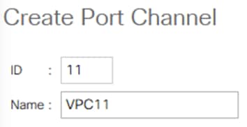
Step 4. Select Create Port Channel.
Step 5. Enter 11 as the unique ID of the Port Channel.
Step 6. Enter VPC11 as the name of the Port Channel.
Step 7. Click Next.
Step 8. Select the port with slot ID: 1 and port: 31 and also the port with slot ID: 1 and port 32 to be added to the Port Channel.
Step 9. Click >> to add the ports to the Port Channel.

Step 10. Click Finish to create the Port Channel.
Step 11. Expand the Port Channel node and click the newly created port channel to view the status.

Note: The port channel formation may take up to 60 seconds.
Step 12. Under LAN Cloud, expand the Fabric B tree.
Step 13. Right-click Port Channels.
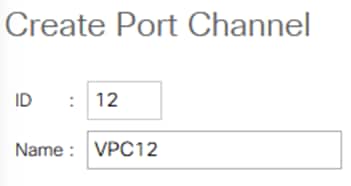
Step 14. Select Create Port Channel.
Step 15. Enter 12 as the unique ID of the Port Channel.
Step 16. Enter VPC12 as the name of the Port Channel.
Step 17. Click Next.
Step 18. Select the port with slot ID: 1 and port: 31 and also the port with slot ID: 1 and port 32 to be added to the Port Channel.
Step 19. Click >> to add the ports to the Port Channel.
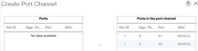
Step 20. Click Finish to create the Port Channel.
Step 21. Expand the Port Channel node and click on the newly created port channel to view the status.

Note: The port channel formation may take up to 60 seconds.
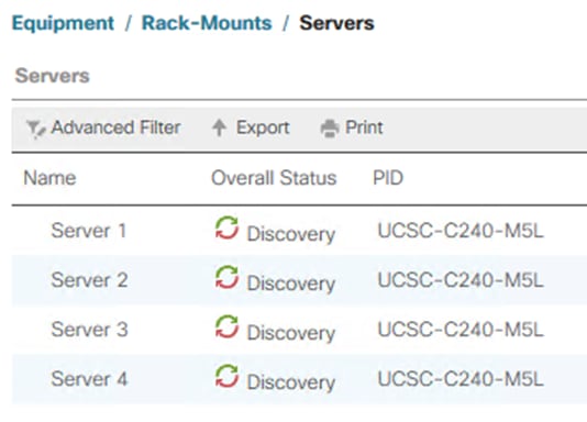
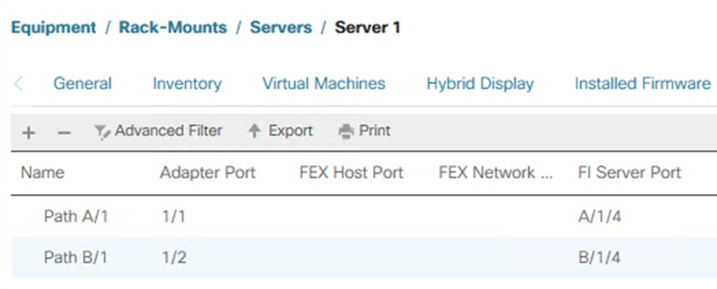
Renumber Servers
Servers may be renumbered out of order. Servers should be numbered based on their physical position in the rack connection to the fabric interconnect port described in Table 4. Servers should be number based on the following table:
| Server Number |
Path Name |
Adapter Port |
FI Server Port |
| Server 1 |
Path A/1 |
1/1 |
A/1/1 |
| Path B/1 |
1/2 |
B/1/1 |
|
| Server 2 |
Path A/1 |
1/1 |
A/1/2 |
| Path B/1 |
1/2 |
B/1/2 |
|
| Server 3 |
Path A/1 |
1/1 |
A/1/3 |
| Path B/1 |
1/2 |
B/1/3 |
|
| Server 4 |
Path A/1 |
1/1 |
A/1/4 |
| Path B/1 |
1/2 |
B/1/4 |
Procedure 1. Renumber the Servers
Note: The server connection to the fabric interconnect port can be identified by checking the VIF path for each server.
Step 1. Select Equipment > Servers > Server 1
Step 2. In the right pane select the VIF Path tab.
Step 3. Note the VIF Paths and repeat steps the remaining servers.
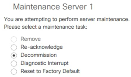
Step 4. Identify the servers with IDs that do not match the FI server port in the table above and decommission them.
Step 5. Select Equipment > Servers > Server 1
Step 6. Right-click Server 1 and select Server Maintenance.
Step 7. Select Decommission and click OK and click Yes to confirm.
Step 8. Repeat steps 1 – 8 for the remaining servers with the wrong VIF Path.
Note: The servers will disappear from the Servers list in the Equipment tree.
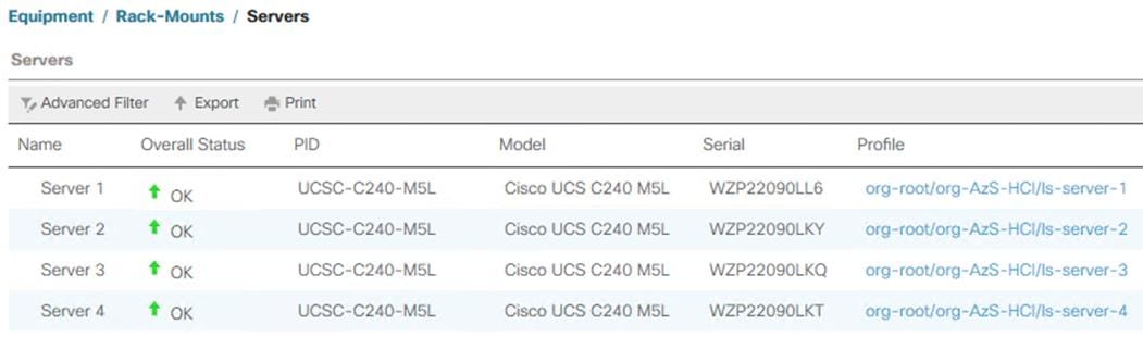
Step 9. Select the Equipment and Decommissioned tab.
Step 10. Expand Rack-Mounts.
Step 11. Double-click on each Server ID number and change it to correspond to the table above.
Step 12. Check the Recommission checkbox next to each server.
Step 13. Click Save Changes to recommission the servers with corrected numbers.
Figure 13. Before Server ID Change

Figure 14. After Server ID Change

The servers will reappear in the Equipment > Servers tree and the server discovery will restart. The services profile created by the auto configuration policy will be associated automatically with the discovered servers once the discovery process completes.
Launch Server KVM Instance to Install the Operating System
Launch KVM to each server after the service profile association is complete. Install the Azur Stack HCI OS 21H2 using PXE boot or a vMedia mapped installation ISO. It is recommended to use PXE boot for OS installation because the installation process will run much faster. Multiple servers can perform OS installation concurrently.
Initial Host Network Configuration
Cisco UCS KVM has a feature called “Paste text from Clipboard.” This feature can copy commands from the clipboard to the selected window in the KVM session. This method can be used to enter commands directly into the PowerShell window.
Procedure 1. Paste Text from Clipboard
Step 1. Copy desired text to the clipboard by selecting the text and pressing Crtl-C.
Step 2. Bring focus to the PowerShell Window in the KVM session.
Step 3. In the top right corner of the KVM window click the File icon and select Paste Text From Clipboard.
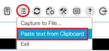
Step 4. Paste the text into the window and click Send.

Step 5. Press Enter to execute the command.
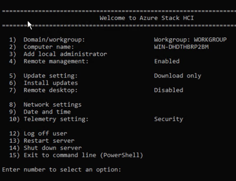
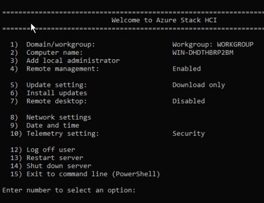
Step 6. Open a KVM session to each host and perform the following configuration to enable remote access to each host. After logging in, start PowerShell by selecting option 15 (“Exit to command line (PowerShell)) in the SConfig screen.
Note: Each host must have a unique host name and IP address for your environment. The following is a table of host names and IP addresses used in this deployment.
| Host Name |
IP Address |
| AzS-HCI-Host01 |
192.168.100.71 |
| AzS-HCI-Host02 |
192.168.100.72 |
| AzS-HCI-Host03 |
192.168.100.73 |
| AzS-HCI-Host04 |
192.168.100.74 |
Procedure 2. Verify the Operating System Version
Step 1. Run the command Get-ComputerInfo | fl -Property OSDisplayVersion:
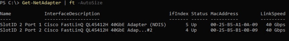
Procedure 3. Verify Available NICs Seen by the Operating System
Step 1. Run the command Get-NetAdapter | ft -AutoSize:
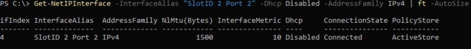
Procedure 4. Disable DHCP on Port 2 of the NIC and Verify the Setting
Step 1. Run the commands Set-NetIPInterface -InterfaceAlias "SlotID 2 Port 2" -Dhcp Disabled and Get-NetIPInterface -InterfaceAlias "SlotID 2 Port 2" -Dhcp Disabled -AddressFamily IPv4 | ft -AutoSize:
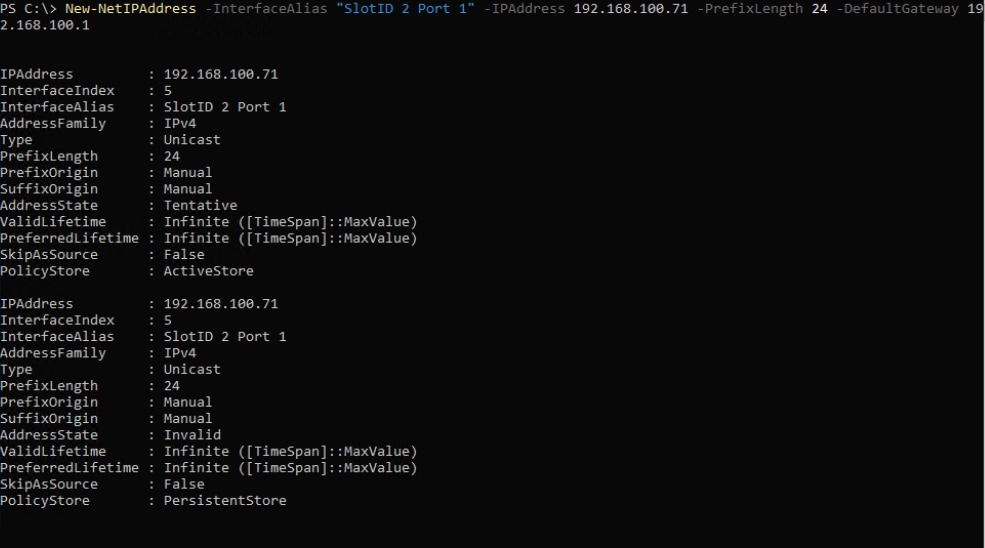
Procedure 5. Configure Static NIC IP Address for Management NIC’s
Note: Replace the IP address with the address specific to your environment.
Note: The VLAN for this subnet must be set to Native because VLAN tagging is not configured for this physical interface. VLAN configuration for the Fabric Interconnects is implemented in Cisco UCS Manager.
Step 1. Run the following command:
New-NetIPAddress -InterfaceAlias "SlotID 2 Port 1" -IPAddress 192.168.100.71 -PrefixLength 24 -DefaultGateway 192.168.100.1
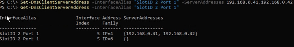
Procedure 6. Configure DNS Client Server IP Address
Note: Replace the DNS Server IP address with the address specific to your environment.
Step 1. Run the following commands:
Set-DnsClientServerAddress -InterfaceAlias "SlotID 2 Port 1" -ServerAddresses 192.168.0.41,192.168.0.42
Get-DnsClientServerAddress -InterfaceAlias "SlotID 2 Port 1"
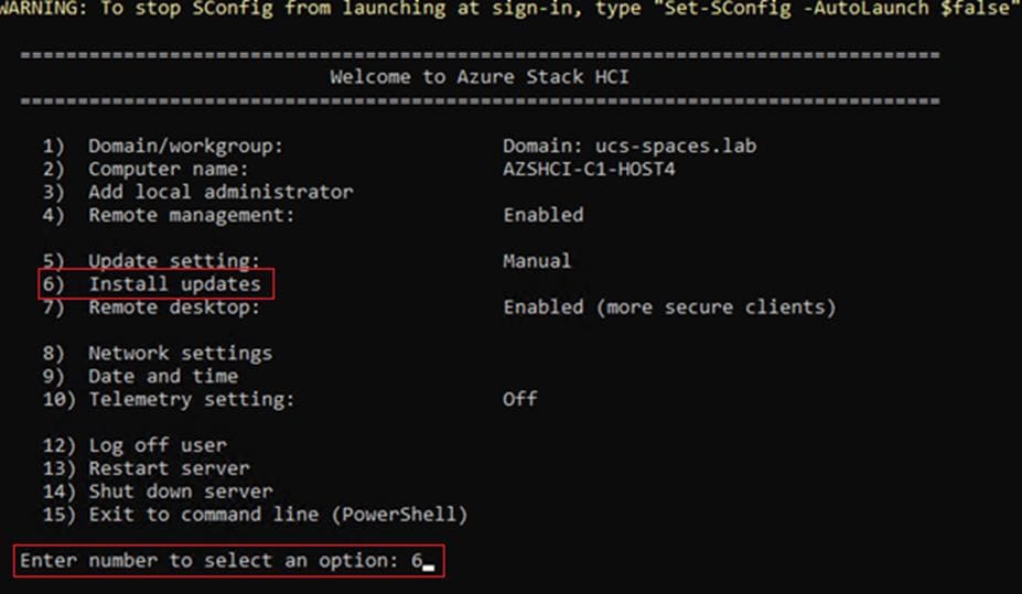
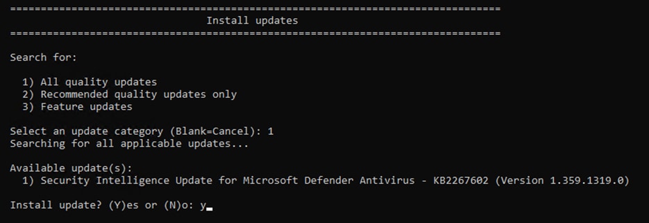
Procedure 7. Install Operating System Updates
Step 1. Select option 6 Install Updates from the SConfig Menu.

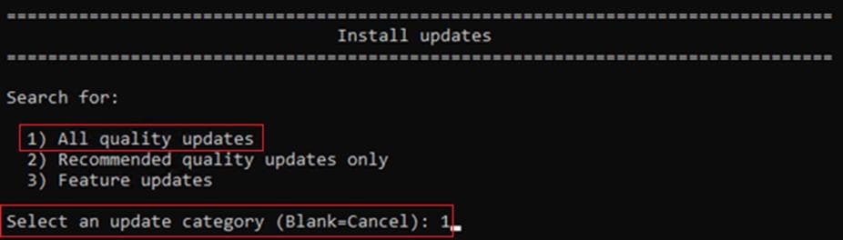
Step 2. Select option 2 All recommended quality updates only from the Install Updates menu.
Step 3. Select the option A to install all recommended quality updates.
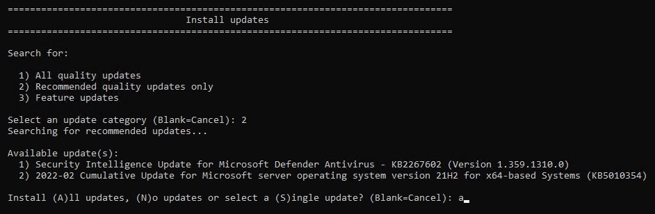
The updates will start downloading and installing.
Step 4. Select the option Y to reboot the server if a reboot is required after the update is installed.
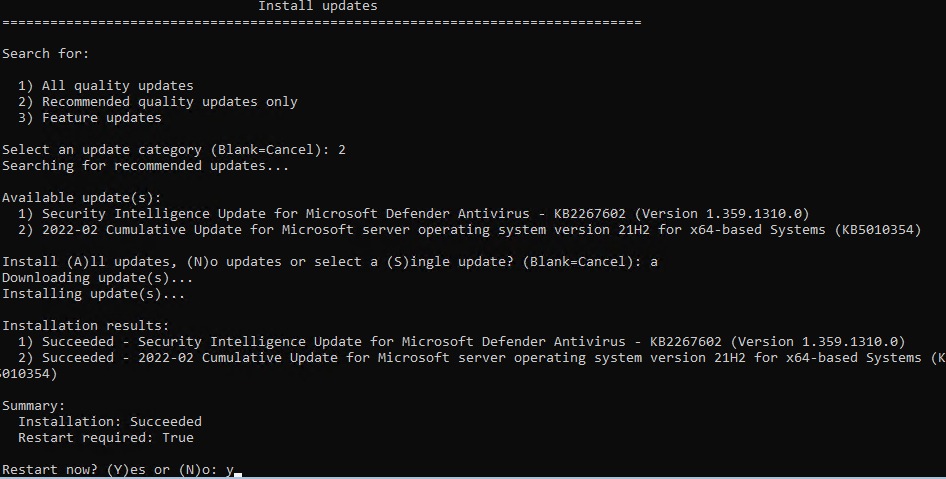
Step 5. After the server reboots, login again and select option 6 Install Updates again from the SConfig Menu.
Step 6. Select option 1 All quality updates from the Install Updates menu.
Step 7. Select option A to install all updates.
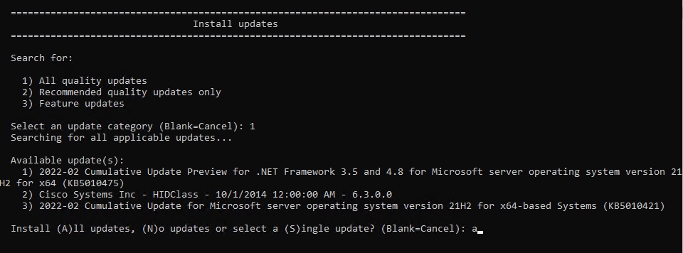
The updates will start downloading and installing.
Step 8. Select the option to reboot the server if a reboot is required after the update is installed.
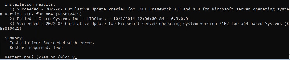
Step 9. Repeat steps 1 - 8 after the server reboots to install any remaining updates
Note: The Cisco update installation may result in an error condition. This error can safely be ignored.
Step 10. After the server reboots, login again and select option 6 Install Updates again from the SConfig Menu.

Step 11. Select option 1 All quality updates form the Install Updates menu.
Step 12. Verify that no other quality updates are available for installation. Install any remaining quality updates.
Step 13. Return to the main SConfig menu.
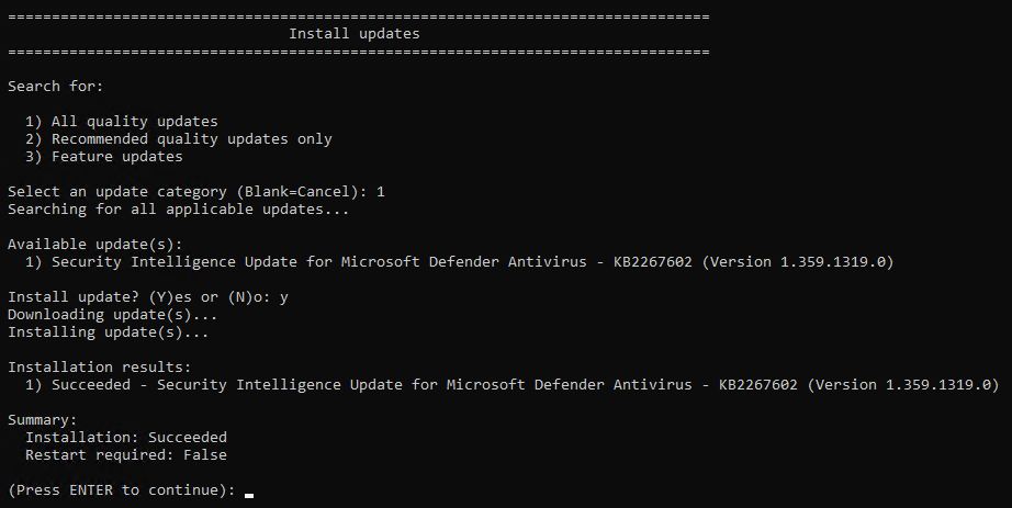
Step 14. Select option 15 Exit to command line (PowerShell) in the SConfig screen.

Procedure 8. Rename Computer
Step 1. Run the command Rename-Computer -NewName AzS-HCI-Host01 -Restart:
![]()
The server restarts after renaming the computer.
Procedure 9. Join the Windows Server to a Domain
Note: Replace the Active Directory Domain name with the domain name and account with domain admin privileges that is specific to your environment. Login with administrative privileges after the server reboot and enter option 15 to start a PowerShell session in the SConfig screen.
Note: The local computer time must be withing 5 minutes of the domain controller time in order the for the computer to join the active directory domain. The local computer date and time can be checked and adjusted using option 9 “Date and Time” in SConfig or by using the PowerShell Get-Date and Set-Date cmdlet.
Step 1. Run the following command to join the computer to the Active Directory domain:
Add-Computer -DomainName ucs-spaces.lab -Credential ucs-spaces.lab\HCIAdmin -Restart
![]()
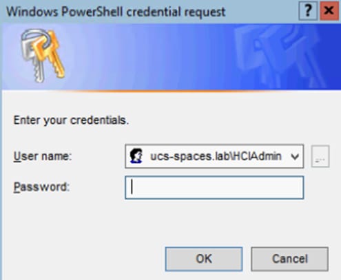
The server restarts after joining the domain.
Note: The following procedures are preformed from a domain joined remote management Host. See the Appendix for Remote Management Host configuration requirements.
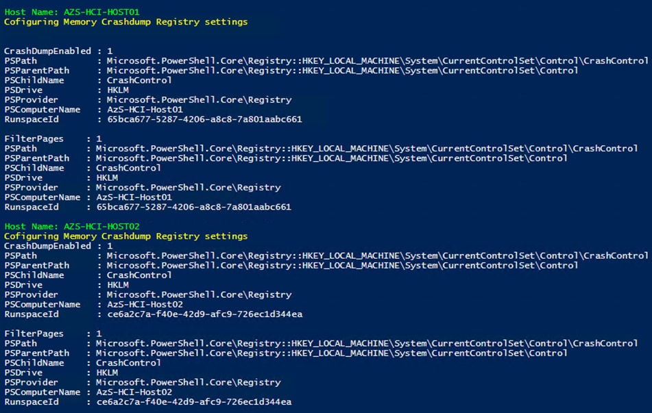
Procedure 10. Configure Windows Memory Crashdump
Note: Hyper-V hosts allocate typically contain a considerable amount of physical memory, but the majority of the physical memory is allocated to virtual machines. For this reason, the parent partition of a Hyper-V host uses a relatively small amount of memory as compared to the total amount of memory installed in the system. The memory dump of the parent partition can provide vital debugging information in the rare case that an unexpected bugcheck (bluescreen) occurs on host.
The following setting enables the creation of a memory dump file and when a bugcheck occurs and use the Active Dump setting to optimize the amount of memory used when a memory dump is created:
$Creds = Get-Credential -Message "Enter Login Credentials" -User ucs-spaces\hciadmin
$nodes = ("AzS-HCI-Host01", "AzS-HCI-Host02", "AzS-HCI-Host03", "AzS-HCI-Host04")
foreach ($node in $nodes) {
Invoke-Command $node -Credential $Creds -scriptblock {
write-host "Host Name:" $env:COMPUTERNAME -ForegroundColor Green
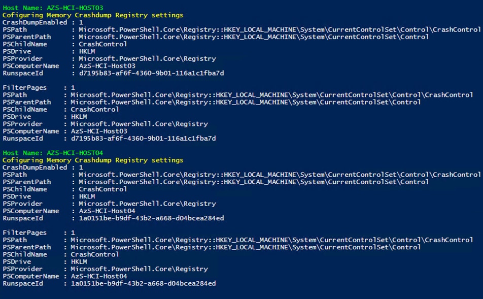
Write-Host "Cofiguring Memory Crashdump Registry settings " -ForegroundColor Yellow
Set-ItemProperty -Path HKLM:\System\CurrentControlSet\Control\CrashControl –Name CrashDumpEnabled -value 1
Set-ItemProperty -Path HKLM:\System\CurrentControlSet\Control\CrashControl –Name FilterPages -value 1
Get-ItemProperty -Path HKLM:\System\CurrentControlSet\Control\CrashControl -Name CrashDumpEnabled
Get-ItemProperty -Path HKLM:\System\CurrentControlSet\Control\CrashControl -Name FilterPages
}
}
Procedure 11. Configure Time Zone
Step 1. Time zone must have the same setting on all cluster nodes. The following script block configures the time zone:
$nodes = ("AzS-HCI-Host01", "AzS-HCI-Host02", "AzS-HCI-Host03", "AzS-HCI-Host04")
foreach ($node in $nodes) {
Invoke-Command $node -Credential $Creds -ScriptBlock {
write-host "Host Name:" $env:COMPUTERNAME -ForegroundColor Green
Write-Host "Configuring time zone..." -ForegroundColor Yellow
Set-Timezone -Name "Pacific Standard Time"
}
}
Note: The time zone is specific to the region. The following command lists available time zones.
Get-TimeZone -ListAvailable | ft StandardName, ID
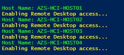
Procedure 12. Enable Remote Desktop Access on the Host Servers
Step 1. Run the following:
$nodes = ("AzS-HCI-Host01", "AzS-HCI-Host02", "AzS-HCI-Host03", "AzS-HCI-Host04")
foreach ($node in $nodes) {
Invoke-Command $node -Credential $Creds -ScriptBlock {
write-host "Host Name:" $env:COMPUTERNAME -ForegroundColor Green
Write-Host "Enabling Remote Desktop access..." -ForegroundColor Yellow
Set-ItemProperty -Path "HKLM:\System\CurrentControlSet\Control\Terminal Server" -Name "fDenyTSConnections" –Value 0
Enable-NetFirewallRule -DisplayGroup "Remote Desktop"
}
}
Procedure 13. Install Windows Features
The following Windows Features are installed:
● Bitlocker
● Data Center Bridging
● Failover Clustering
● Hyper-V
● Hyper-V PowerShell
● Active Directory Remote Management PowerShell
● Cluster Management PowerShell
● File Server
● SMB Bandwidth Limit
● NetworkATC
● FS-Data-Deduplication
$nodes = ("AzS-HCI-Host01", "AzS-HCI-Host02", "AzS-HCI-Host03", "AzS-HCI-Host04")
foreach ($node in $nodes) {
Invoke-Command $node -Credential $Creds -scriptblock {
write-host "Host Name:" $env:COMPUTERNAME -ForegroundColor Green
Write-Host "Enabling Required Windows Features and Restarting Host Server..." -ForegroundColor Yellow
Add-WindowsFeature -Name Hyper-V,Failover-Clustering,Data-Center-Bridging,Bitlocker,FS-FileServer, FS-SMBBW, Hyper-V-PowerShell,RSAT-AD-Powershell,RSAT-Clustering-PowerShell, NetworkATC, FS-DATA-Deduplication, RSAT-AD-Powershell -IncludeAllSubFeature -IncludeManagementTools -Restart
}
}
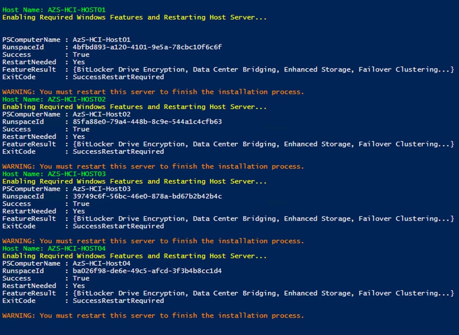
Note: Each server node will reboot automatically to complete the feature installation process. Confirm that each server reboots successfully.
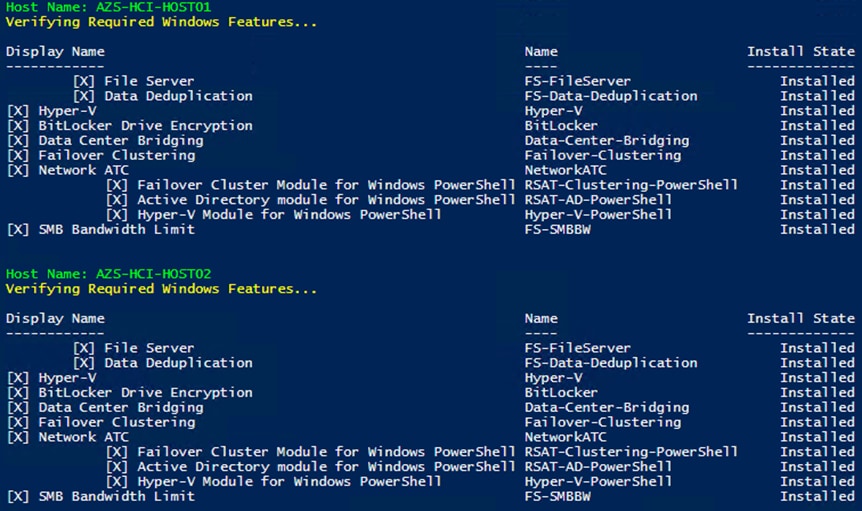
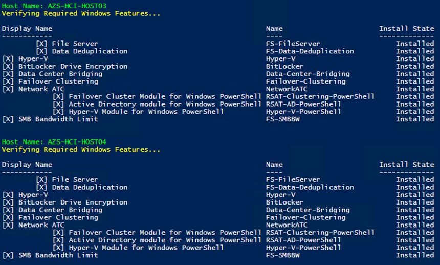
Procedure 14. Verify installed Windows Features
Step 1. Run the following:
$nodes = ("AzS-HCI-Host01", "AzS-HCI-Host02", "AzS-HCI-Host03", "AzS-HCI-Host04")
foreach ($node in $nodes) {
Invoke-Command $node -Credential $Creds -scriptblock {
write-host "Host Name:" $env:COMPUTERNAME -ForegroundColor Green
Write-Host "Verifying Required Windows Features..." -ForegroundColor Yellow
}
}
Configure Bitlocker for System Volume
Using Bitlocker to encrypt system volume is an optional procedure in the deployment. TPM will be the primary key protector for the encrypted volume. The TPM will automatically decrypt the system volume at boot time. A recovery password will be an additional key protector in case the TPM fails. The recovery password will be backed up and stored in Active Directory Domain Service.
Procedure 1. Verify that Secure Boot is Enabled
Step 1. Run the following:
$nodes = ("AzS-HCI-Host01", "AzS-HCI-Host02", "AzS-HCI-Host03", "AzS-HCI-Host04")
foreach ($node in $nodes) {
Invoke-Command $node -Credential $Creds -scriptblock {
write-host "Host Name:" $env:COMPUTERNAME
Write-Host "Checking Secure Boot Status " -ForegroundColor Yellow
Confirm-SecureBootUEFI
}
}
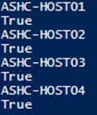
Procedure 2. Enable Bitlocker Group Policy
Note: A local group policy needs to be enabled. This local group policy allows the Recovery Password to be backed up to Active Directory Domain Service.
Step 1. Run the following:
$nodes = ("AzS-HCI-Host01", "AzS-HCI-Host02", "AzS-HCI-Host03", "AzS-HCI-Host04")
foreach ($node in $nodes) {
Invoke-Command $node -Credential $Creds -scriptblock {
write-host "Host Name:" $env:COMPUTERNAME -ForegroundColor Green
Write-Host "Cofiguring Bitlocker Registry settings to allow recovery password backup to AD... " -ForegroundColor Yellow
New-Item -Path HKLM:\SOFTWARE\Policies\Microsoft -Name FVE
New-ItemProperty -Path HKLM:\SOFTWARE\Policies\Microsoft\FVE -Name "OSRecovery" -Value ”1” -PropertyType DWORD
New-ItemProperty -Path HKLM:\SOFTWARE\Policies\Microsoft\FVE -Name "OSManageDRA" -Value ”1” -PropertyType DWORD
New-ItemProperty -Path HKLM:\SOFTWARE\Policies\Microsoft\FVE -Name "OSRecoveryPassword" -Value ”2” -PropertyType DWORD
New-ItemProperty -Path HKLM:\SOFTWARE\Policies\Microsoft\FVE -Name "OSRecoveryKey" -Value ”2” -PropertyType DWORD
New-ItemProperty -Path HKLM:\SOFTWARE\Policies\Microsoft\FVE -Name "OSHideRecoveryPage" -Value ”0” -PropertyType DWORD
New-ItemProperty -Path HKLM:\SOFTWARE\Policies\Microsoft\FVE -Name "OSActiveDirectoryBackup" -Value ”1” -PropertyType DWORD
New-ItemProperty -Path HKLM:\SOFTWARE\Policies\Microsoft\FVE -Name "OSActiveDirectoryInfoToStore" -Value ”1” -PropertyType DWORD
New-ItemProperty -Path HKLM:\SOFTWARE\Policies\Microsoft\FVE -Name "OSRequireActiveDirectoryBackup" -Value ”0” -PropertyType DWORD
Get-ItemProperty -path HKLM:\SOFTWARE\Policies\Microsoft\FVE -Name "OSRecovery"
Get-ItemProperty -path HKLM:\SOFTWARE\Policies\Microsoft\FVE -Name "OSManageDRA"
Get-ItemProperty -path HKLM:\SOFTWARE\Policies\Microsoft\FVE -Name "OSRecoveryPassword"
Get-ItemProperty -path HKLM:\SOFTWARE\Policies\Microsoft\FVE -Name "OSHideRecoveryPage"
Get-ItemProperty -path HKLM:\SOFTWARE\Policies\Microsoft\FVE -Name "OSActiveDirectoryBackup"
Get-ItemProperty -path HKLM:\SOFTWARE\Policies\Microsoft\FVE -Name "OSActiveDirectoryInfoToStore"
Get-ItemProperty -path HKLM:\SOFTWARE\Policies\Microsoft\FVE -Name "OSRequireActiveDirectoryBackup"
}
}
Procedure 3. Create and Backup Recovery Password
Note: Create the recover password key protector and back it up to Active Directory Domain Service.
Step 1. Run the following:
$nodes = ("AzS-HCI-Host01", "AzS-HCI-Host02", "AzS-HCI-Host03", "AzS-HCI-Host04")
foreach ($node in $nodes) {
Invoke-Command $node -Credential $Creds -scriptblock {
write-host "Host Name:" $env:COMPUTERNAME -ForegroundColor Green
Write-Host "Creating and Backing Up Recovery Key " -ForegroundColor Yellow
Add-BitLockerKeyProtector -MountPoint "C:" -RecoveryPasswordProtector
$KPID = ((Get-BitLockerVolume -MountPoint "C:").KeyProtector | ? KeyProtectorType -EQ "RecoveryPassword").KeyProtectorId
Backup-BitLockerKeyProtector -MountPoint "C:" -KeyProtectorId $KPID
}
}
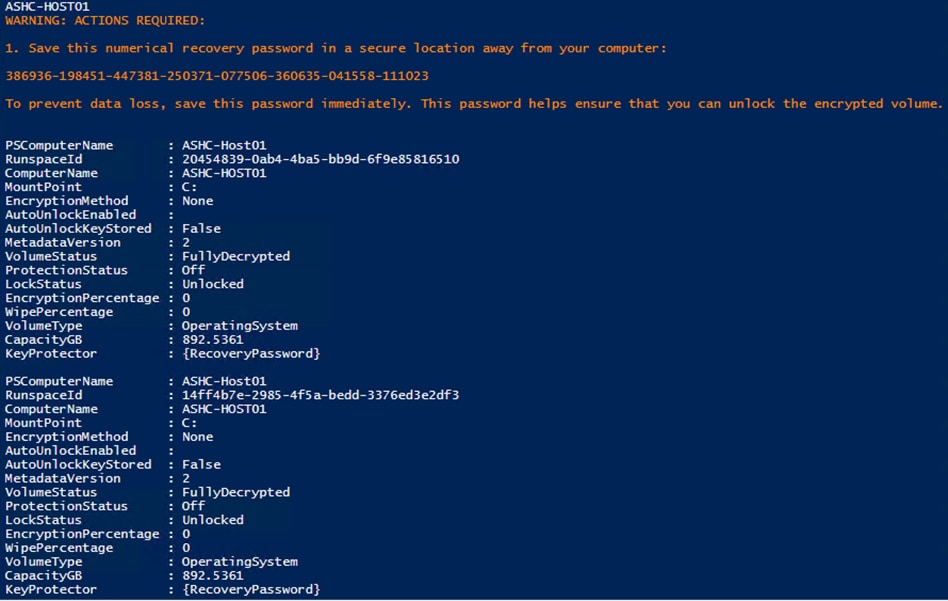
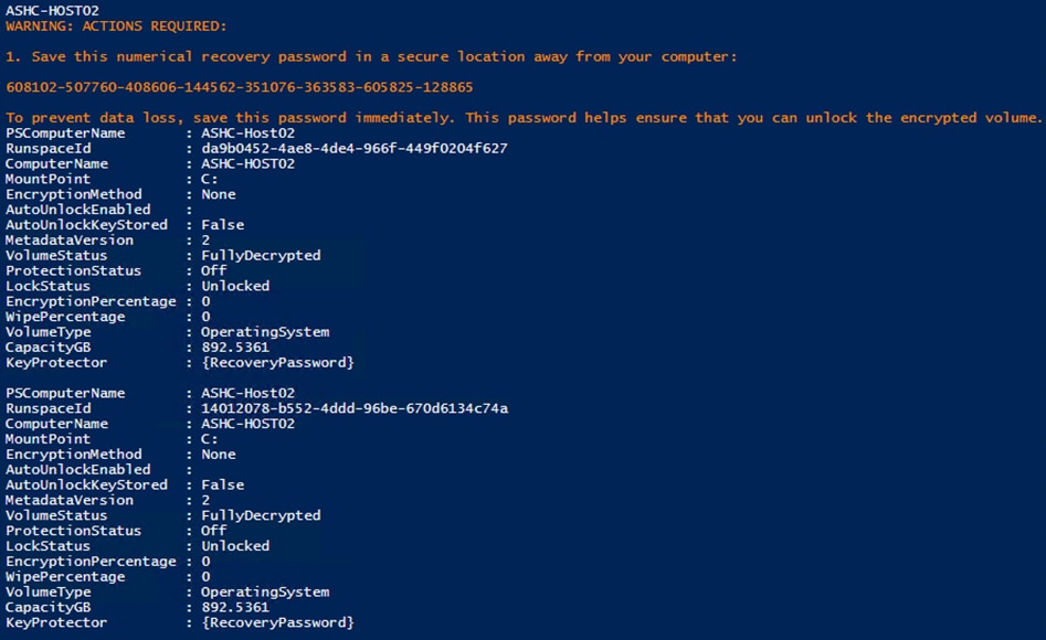
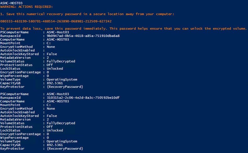
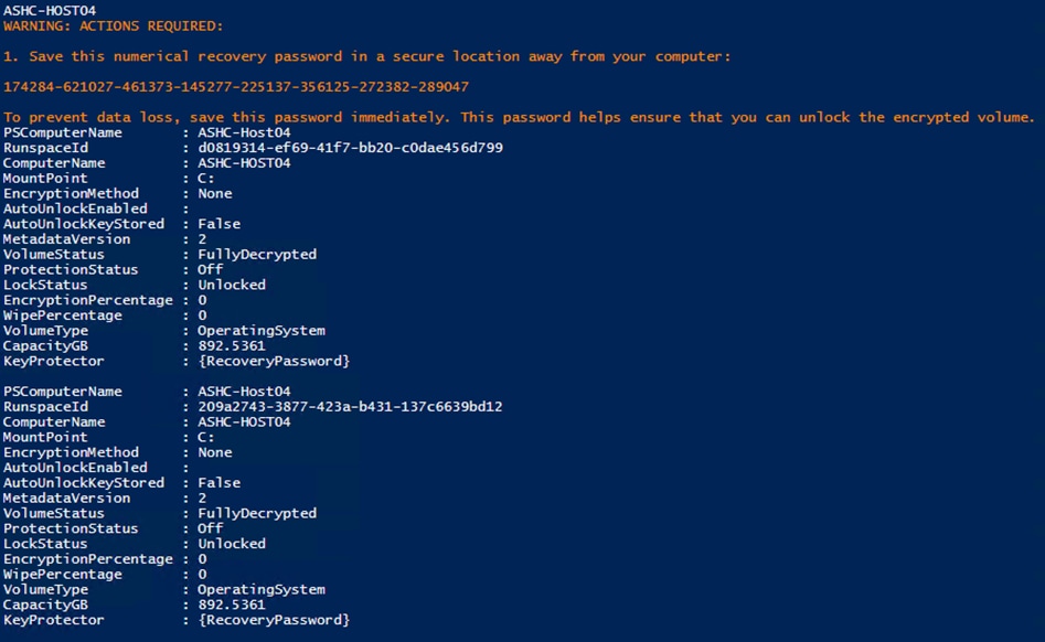
Procedure 4. Enable Bitlocker
Note: Enable Bitlocker for the system volume and add the TPM protector. Encryption of the system volume will not start until the server is rebooted.
Step 1. Run the following:
$nodes = ("AzS-HCI-Host01", "AzS-HCI-Host02", "AzS-HCI-Host03", "AzS-HCI-Host04")
foreach ($node in $nodes) {
Invoke-Command $node -Credential $Creds -scriptblock {
write-host "Host Name:" $env:COMPUTERNAME -ForegroundColor Green
Write-Host "Enabling Bitlocker Protection " -ForegroundColor Yellow
Enable-BitLocker -MountPoint "C:" -EncryptionMethod XtsAes256 -UsedSpaceOnly -TpmProtector
}
}
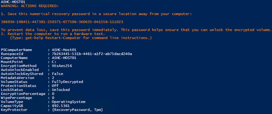
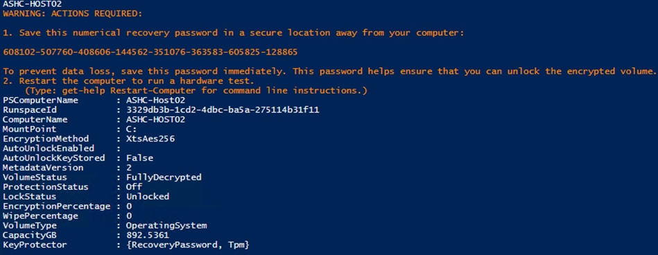
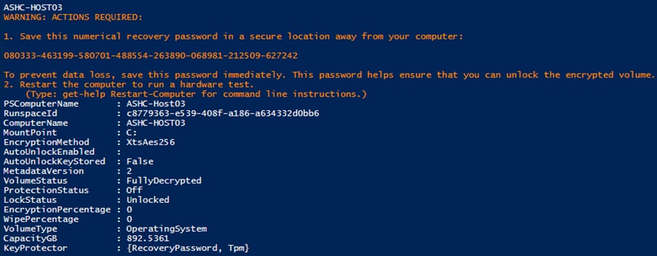
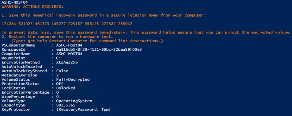
Procedure 5. Reboot Server to Enable Bitlocker for the System Volume
Note: Bitlocker will enable the when the server reboots. Bitlocker verifies that the key protectors are correctly configure. Volume encryption will take a few minutes to complete after the server reboots.
Step 1. Run the following:
$nodes = ("AzS-HCI-Host01", "AzS-HCI-Host02", "AzS-HCI-Host03", "AzS-HCI-Host04")
foreach ($node in $nodes) {
Invoke-Command $node -Credential $Creds -scriptblock {
write-host "Host Name:" $env:COMPUTERNAME -ForegroundColor Green
Write-Host "Restarting Host After Enabling Bitlocker Protection " -ForegroundColor Yellow
Restart-Computer -Force
}
}
Procedure 6. Verify Bitlocker Status
Note: Verify the Bitlocker Protection Status and Encryption Percentage.
Step 1. Run the following:
$nodes = ("AzS-HCI-Host01", "AzS-HCI-Host02", "AzS-HCI-Host03", "AzS-HCI-Host04")
foreach ($node in $nodes) {
Invoke-Command $node -Credential $Creds -scriptblock {
write-host "Host Name:" $env:COMPUTERNAME -ForegroundColor Green
Write-Host "Verifying Bitlocker Protection Status " -ForegroundColor Yellow
Get-BitlockerVolume -MountPoint "c:" | FT
}
}
Note: Bitlocker protection status will indicate “Off” until encryption reaches 100%.
Procedure 7. Verity Bitlocker Recovery Password Backup
Note: Bitlocker Recovery Password View provides the ability to read the backup of the recovery password that that is backed up to Active Directory Domain Services. This is an optional Windows feature that can be installed by running the following PowerShell command on a system that will be sued to read the password from Active Directly Domain Services.
Step 1. Add-WindowsFeature -Name RSAT-Feature-Tools-BitLocker-BdeAducExt
The following PowerShell scriptblock retrieves the Bitlocker password that is backed up to Active Directory:
$nodes = ("AzS-HCI-Host01", "AzS-HCI-Host02", "AzS-HCI-Host03", "AzS-HCI-Host04")
foreach ($node in $nodes) {
$objComputer = Get-ADComputer $node
write-host "Host Name:" $node -ForegroundColor Green
$Bitlocker_Objects = Get-ADObject -Filter {objectclass -eq 'msFVE-RecoveryInformation'} -SearchBase $objComputer.DistinguishedName -Properties 'msFVE-RecoveryPassword'
foreach ($Bitlocker_Object in $Bitlocker_Objects) {
Write-Host "Date, Time, and Password ID:" ($Bitlocker_Objects).Name
Write-Host "Recovery Password:" ($Bitlocker_Objects).'msFVE-RecoveryPassword' -ForegroundColor Cyan -Separator " "
Write-Host ""
}
}
Details on accessing the recovery password backup can be found at the following link. Recovery passwords backup should be verified as part of every deployment: https://docs.microsoft.com/en-us/windows/security/information-protection/bitlocker/bitlocker-use-bitlocker-recovery-password-viewer
Organizations using Bitlocker should be familiar with Bitlocker recovery procedures in case recovering access to a Bitlocker protected volume is required. The Microsoft guide to Bitlocker recovery can be found at the following link: https://docs.microsoft.com/en-us/windows/security/information-protection/bitlocker/bitlocker-recovery-guide-plan
The subject contains the following procedures:
● Identify Physical Network Card Port Names
● Create and Deploy Standalone Network ATC Intent
● Verify Network ATC Intent Status
● Verify Virtual Switch and Virtual NIC Creation in the Parent Partition
● Verify SET Switch Team Load Balancing Algorithm
● Configure Default Route Metric for Management NIC in Parent Partition
● Configure Static NIC IP Address for Storage NICs
● Verify NIC IP Address for Storage NICs
● Verify DNS Registration is Removed for Storage Interfaces
● Enable Preserving 802.1p Priority Marking to Pass Through the vSwitch
● Verify the Storage vNIC VLANs
● Verify RDMA and RoCEv2 Protocol is Enabled on Physical NICs
● Verify that RDMA is Enabled on the Storage vNIC Adapters
● Verify the Mapping of each SMB-Direct NIC to the respective Fabric
Procedure 1. Identify Physical Network Card Port Names
Step 1. Run the following:
$nodes = ("AzS-HCI-Host01", "AzS-HCI-Host02", "AzS-HCI-Host03", "AzS-HCI-Host04")
foreach ($node in $nodes) {
Invoke-Command $node -Credential $Creds -scriptblock {
write-host "Host Name:" $env:COMPUTERNAME -ForegroundColor Green
Write-Host " Retrieving physical NIC port names " -ForegroundColor Yellow
Get-netadapter | ft Name, InterfaceDescription, Status, MacAddress, LinkSpeed
}
}
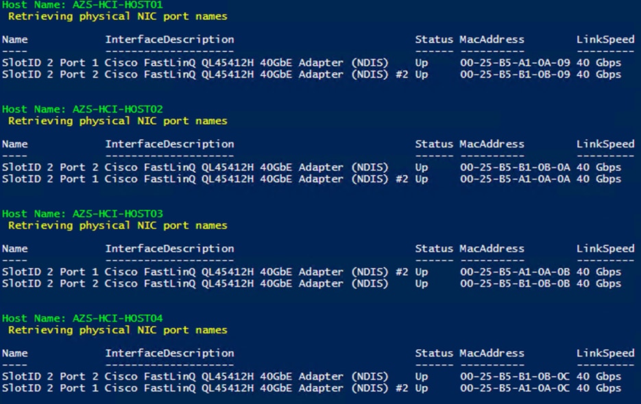
Note: If the NIC port names are “Ethernet” and “Ethernet 2”, CDN is not enabled. CDN (Consistent Device Naming) must be enabled for correct physical to virtual NIC mapping later in this guide.
Procedure 2. Create and Deploy Standalone Network ATC Intent
Step 1. Run the following script block to create a virtual switch with SET enabled and three virtual NICs:
$nodes = ("AzS-HCI-Host01", "AzS-HCI-Host02", "AzS-HCI-Host03", "AzS-HCI-Host04")
foreach ($node in $nodes) {
Invoke-Command $node -Credential $Creds -scriptblock {
write-host "Host Name:" $env:COMPUTERNAME -ForegroundColor Green
Write-Host " Create and Deploy Standalone Network ATC Intent " -ForegroundColor Yellow
$QoSOverride = New-NetIntentQoSPolicyOverRides
$AdapterOverride = New-NetIntentAdapterPropertyOverrides
$QoSOverride.PriorityValue8021Action_SMB = 1
$QoSOverride.PriorityValue8021Action_Cluster = 5
$AdapterOverride.NetworkDirectTechnology = 4
$QoSOverride
$AdapterOverride
Add-NetIntent -AdapterName "SlotID 2 Port 1", "SlotID 2 Port 2" -Management -Compute -Storage -StorageVlans 107, 207 -QoSPolicyOverrides $QoSOverride -AdapterPropertyOverrides $AdapterOverride -Name Mgmt_Compute_Storage
}
}
Procedure 3. Verify Network ATC Intent Status
Step 1. Run the following:
$nodes = ("AzS-HCI-Host01", "AzS-HCI-Host02", "AzS-HCI-Host03", "AzS-HCI-Host04")
foreach ($node in $nodes) {
Invoke-Command $node -Credential $Creds -scriptblock {
write-host "Host Name:" $env:COMPUTERNAME -ForegroundColor Green
Write-Host " Checking Network ATC Intent Status" -ForegroundColor Yellow
Get-netIntentStatus -ComputerName $node | ft Host,IntentName,ConfigurationStatus,ProvisioningStatus,IsComputeIntentSet,IsComputeIntentSet,IsComputeIntentSet
}
}
Procedure 4. Verify Virtual Switch and Virtual NIC Creation in the Parent Partition
$nodes = ("AzS-HCI-Host01", "AzS-HCI-Host02", "AzS-HCI-Host03", "AzS-HCI-Host04")
foreach ($node in $nodes) {
Invoke-Command $node -Credential $Creds -scriptblock {
write-host "Host Name:" $env:COMPUTERNAME -ForegroundColor Green
Write-Host " Verifying Virtual Switch " -ForegroundColor Yellow
Get-VMSwitch | fl Name, SwitchType, NetAdapterInterfaceDescription, NetAdapterInterfaceDescriptions
Write-Host " Verifying Management vNIC in parent partition " -ForegroundColor Yellow
Get-netadapter | ft Name, InterfaceDescription, Status, MacAddress, LinkSpeed
}
}
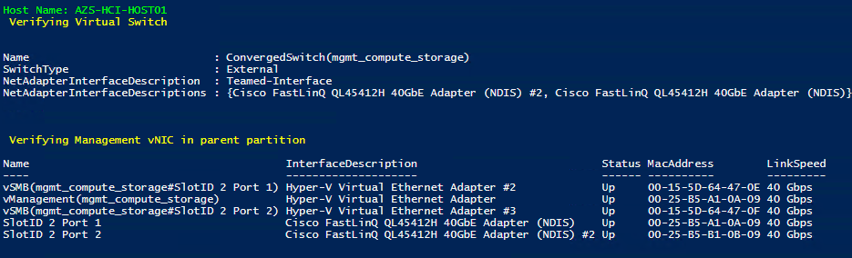
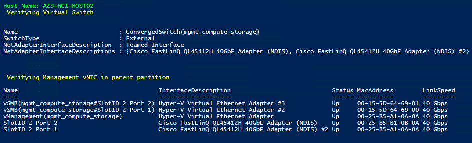
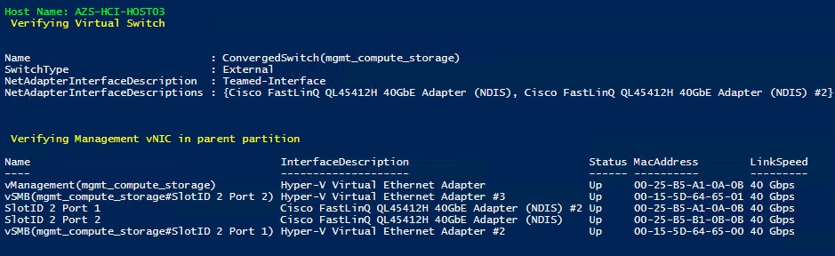
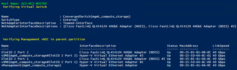
Note: There will be a brief network disconnect on each server node when VM switch binds to the physical adapters.
Procedure 5. Verify SET Switch Team Load Balancing Algorithm
Note: The load balancing algorithm must be a Hyper-V Port. Each VM switch must be bound to both physical network adapters.
$nodes = ("AzS-HCI-Host01", "AzS-HCI-Host02", "AzS-HCI-Host03", "AzS-HCI-Host04")
foreach ($node in $nodes) {
Invoke-Command $node -Credential $Creds -scriptblock {
write-host "Host Name:" $env:COMPUTERNAME -ForegroundColor Green
Write-Host " Verifying SET Switch Load Balancing Algorithm " -ForegroundColor Yellow
Get-VMSwitch | Get-VMSwitchTeam | fl
}
}
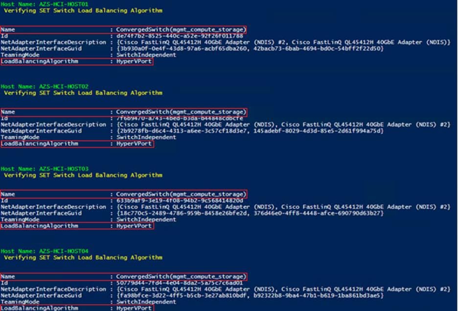
Procedure 6. Configure Default Route Metric for Management NIC in Parent Partition
Step 1. Run the following:
$nodes = ("AzS-HCI-Host01", "AzS-HCI-Host02", "AzS-HCI-Host03", "AzS-HCI-Host04")
foreach ($node in $nodes) {
Invoke-Command $node -Credential $Creds -scriptblock {
write-host "Host Name:" $env:COMPUTERNAME -ForegroundColor Green
Write-Host "Configuring default route metric for Management NIC " -ForegroundColor Yellow
netsh in ipv4 set ro 0.0.0.0/0 "vManagement(mgmt_compute_storage)” met=5
route print -4
}
}
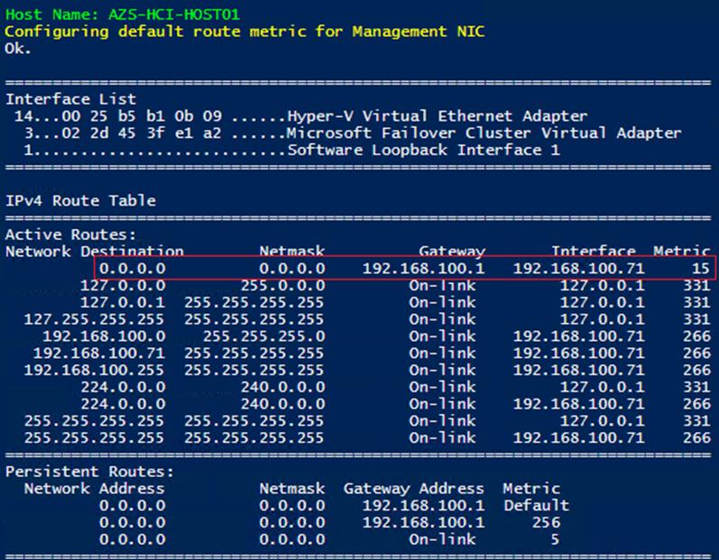
Procedure 7. Configure Static NIC IP Address for Storage NIC’s
Note: Leave gateway unconfigured for storage NICs.
| Host |
SMB NIC Name |
SMB NIC IP Address |
| AzS-HCI-Host01
|
SMB-A |
192.168.107.71 |
| SMB-B |
192.168.207.71 |
|
| AzS-HCI-Host02
|
SMB-A |
192.168.107.72 |
| SMB-B |
192.168.207.72 |
|
| AzS-HCI-Host03
|
SMB-A |
192.168.107.73 |
| SMB-B |
192.168.207.73 |
|
| AzS-HCI-Host04 |
SMB-A |
192.168.107.74 |
| SMB-B |
192.168.207.74 |
$nodes = (
"AzS-HCI-Host01",
"AzS-HCI-Host02",
"AzS-HCI-Host03",
"AzS-HCI-Host04")
$IPStorageNetA = "192.168.107." # vSMB(mgmt_compute_storage#SlotID 2 Port 1)networkaddress
$IPStorageNetB = "192.168.207." #vSMB(mgmt_compute_storage#SlotID 2 Port 2) networkaddress
$IPHostAddr = 71 #Starting host address
foreach ($node in $nodes) {
$session = New-CimSession -ComputerName $node
New-NetIPAddress -CimSession $session -InterfaceAlias "vSMB(mgmt_compute_storage#SlotID 2 Port 1)" -IPAddress ($IPStorageNetA+$IPHostAddr.ToString()) -PrefixLength 24
New-NetIPAddress -CimSession $session -InterfaceAlias "vSMB(mgmt_compute_storage#SlotID 2 Port 2)" -IPAddress ($IPStorageNetB+$IPHostAddr.ToString()) -PrefixLength 24
$IPHostAddr++
}
Get-CimSession | Remove-CimSession
Remove-Variable session
Note: Network connectivity may be temporarily disrupted during the following configuration operations, but connectivity will automatically recover.

Procedure 8. Verify NIC IP Address for Storage NICs
Step 1. Run the following:
$nodes = ("AzS-HCI-Host01", "AzS-HCI-Host02", "AzS-HCI-Host03", "AzS-HCI-Host04")
foreach ($node in $nodes) {
Invoke-Command $node -Credential $Creds -scriptblock {
write-host "Host Name:" $env:COMPUTERNAME -ForegroundColor Green
Write-Host "Verifying Storage NIC IP Address " -ForegroundColor Yellow
Get-NetIPConfiguration -InterfaceAlias vSMB* | fl InterfaceAlias, IPv4Address, IPv4DefaultGateway
}
}
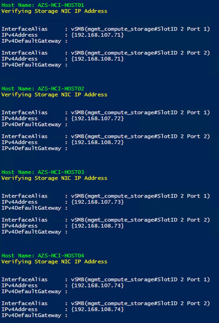
Procedure 9. Verify DNS Registration is Removed for Storage Interfaces
Step 1. Run the following:
$nodes = ("AzS-HCI-Host01", "AzS-HCI-Host02", "AzS-HCI-Host03", "AzS-HCI-Host04")
foreach ($node in $nodes) {
Invoke-Command $node -Credential $Creds -scriptblock {
write-host "Host Name:" $env:COMPUTERNAME -ForegroundColor Green
Write-Host "Removing DNS Restistration from Storage NICs " -ForegroundColor Yellow
Set-DnsClient -InterfaceAlias "vSMB(mgmt_compute_storage#SlotID 2 Port 1)" -RegisterThisConnectionsAddress:$false
Set-DnsClient -InterfaceAlias "vSMB(mgmt_compute_storage#SlotID 2 Port 2)" -RegisterThisConnectionsAddress:$false
Get-DnsClient -InterfaceAlias "vSMB(mgmt_compute_storage#SlotID 2 Port 1)"| ft InterfaceAlias,RegisterThisConnectionsAddress
Get-DnsClient -InterfaceAlias "vSMB(mgmt_compute_storage#SlotID 2 Port 2)"| ft InterfaceAlias,RegisterThisConnectionsAddress
}
}
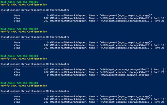
Procedure 10. Enable Preserving 802.1p Priority Marking to Pass Through the vSwitch
Note: The virtual switch zeros-out 802.1p priority marking in the packet header. This is the default behavior. Preserving the 802.1p priority marking in the packet header is required for classifying and prioritizing network traffic in the fabric and other northbound switches that have QoS policies configured. This setting affects prioritized network traffic traversing the virtual switch. This setting is required prioritizing Cluster Communication network traffic. RDMA traffic passing through RDMA enabled vNICs is not affected by this setting because this traffic bypasses the virtual switch and goes directly to the physical NIC.
Step 1. Run the following:
$nodes = ("AzS-HCI-Host01", "AzS-HCI-Host02", "AzS-HCI-Host03", "AzS-HCI-Host04")
foreach ($node in $nodes) {
Invoke-Command $node -Credential $Creds -scriptblock {
write-host "Host Name:" $env:COMPUTERNAME -ForegroundColor Green
Write-Host "Configure vSwitch to pass 802.1p priority marking " -ForegroundColor Yellow
Set-VMNetworkAdapter -Name “vManagement(mgmt_compute_storage)" -ManagementOS -IeeePriorityTag On
Get-VMNetworkAdapter -ManagementOS | ft Name,IeeePriorityTag
}
}
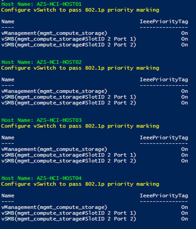
Procedure 11. Verify the Storage vNIC VLANs
Step 1. Run the following:
$nodes = ("AzS-HCI-Host01", "AzS-HCI-Host02", "AzS-HCI-Host03", "AzS-HCI-Host04")
foreach ($node in $nodes) {
Invoke-Command $node -Credential $Creds -scriptblock {
write-host "Host Name:" $env:COMPUTERNAME -ForegroundColor Green
Write-Host "Verify vNIC VLANs Configuration " -ForegroundColor Yellow
Get-VMNetworkAdapter -ManagementOS | Get-VMNetworkAdapterIsolation | FT IsolationMode, DefaultIsolationID, ParentAdapter -AutoSize
}
}
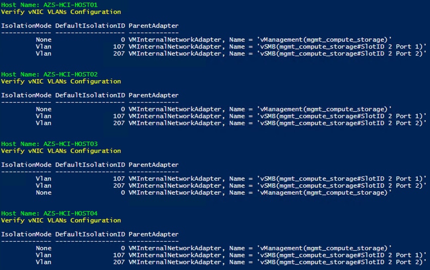
Procedure 12. Verify Network Adapters
Step 1. Run the following:
$nodes = ("AzS-HCI-Host01", "AzS-HCI-Host02", "AzS-HCI-Host03", "AzS-HCI-Host04")
foreach ($node in $nodes) {
Invoke-Command $node -Credential $Creds -scriptblock {
write-host "Host Name:" $env:COMPUTERNAME -ForegroundColor Green
Write-Host "Verifying NIC status " -ForegroundColor Yellow
Get-NetAdapter | sort Name | ft Name,InterfaceDescription,Status,MTUSize,LinkSpeed
}
}
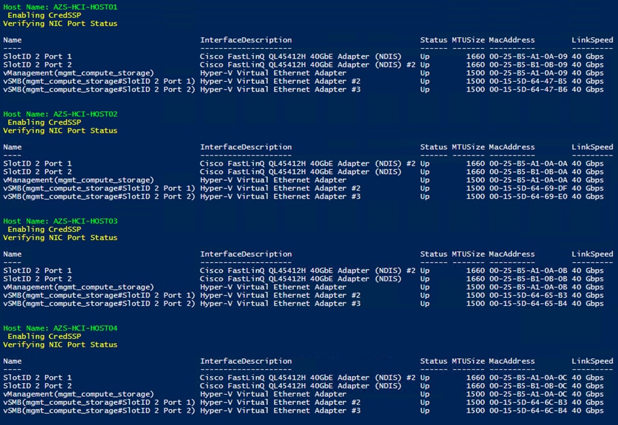
Procedure 13. Verify RDMA and RoCEv2 Protocol is Enabled on Physical NICs
Step 1. Run the following:
$nodes = ("AzS-HCI-Host01", "AzS-HCI-Host02", "AzS-HCI-Host03", "AzS-HCI-Host04")
foreach ($node in $nodes) {
Invoke-Command $node -Credential $Creds -scriptblock {
write-host "Host Name:" $env:COMPUTERNAME -ForegroundColor Green
Write-Host "Verifying RDMA and RoCEv2 status on physical NICS " -ForegroundColor Yellow
Get-NetAdapterAdvancedProperty -InterfaceDescription "Cisco FastLinQ QL45412H*" -DisplayName "NetworkDirect*" | ft Name, InterfaceDescription, DisplayName,DisplayValue
}
}
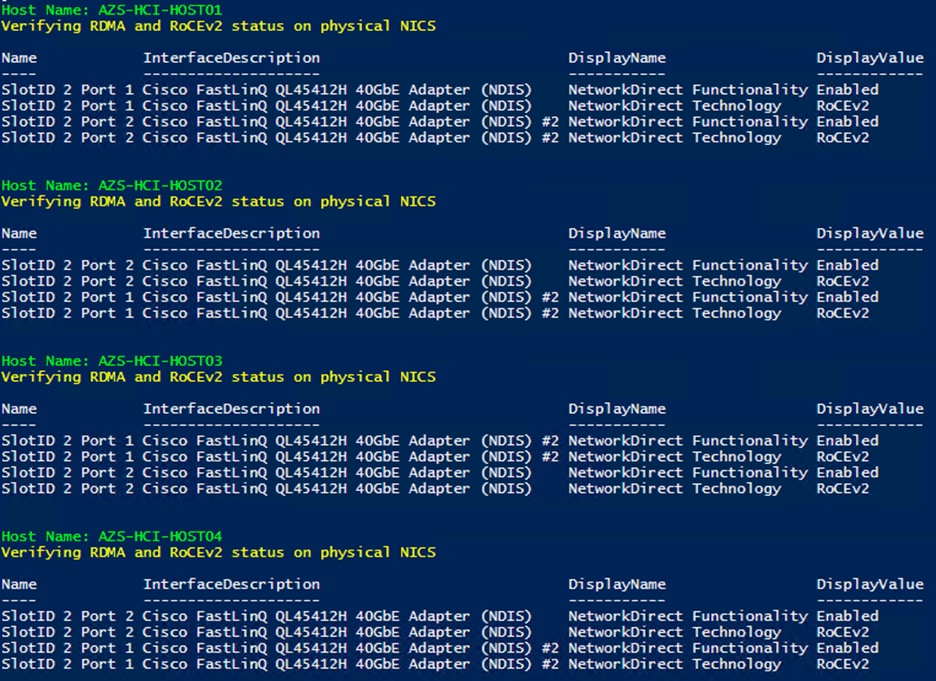
Procedure 14. Verify that RDMA is Enabled on the Storage vNIC Adapters
Step 1. Run the following:
$nodes = ("AzS-HCI-Host01", "AzS-HCI-Host02", "AzS-HCI-Host03", "AzS-HCI-Host04")
foreach ($node in $nodes) {
Invoke-Command $node -Credential $Creds -scriptblock {
write-host "Host Name:" $env:COMPUTERNAME -ForegroundColor Green
Write-Host "Verifying that RDMA is enabled on the Storage vNICs " -ForegroundColor Yellow
Get-NetAdapterRdma | ft
}
}
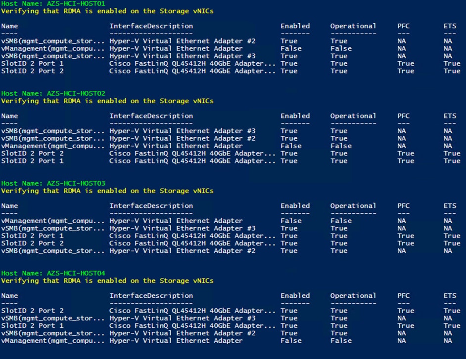
Procedure 15. Verify the Mapping of each SMB-Direct NIC to the respective Fabric
Step 1. Run the following:
$nodes = ("AzS-HCI-Host01", "AzS-HCI-Host02", "AzS-HCI-Host03", "AzS-HCI-Host04")
foreach ($node in $nodes) {
Invoke-Command $node -Credential $Creds -scriptblock {
write-host "Host Name:" $env:COMPUTERNAME -ForegroundColor Green
Write-Host "Verify Mapping of each storage vNIC to the respective fabric " -ForegroundColor Yellow
Get-VMNetworkAdapterTeamMapping -ManagementOS | ft ComputerName,NetAdapterName,ParentAdapter
}
}
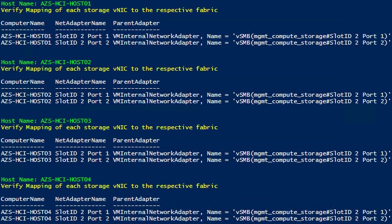
Procedure 16. Verify RDMA Capabilities
Step 1. Run the following:
$nodes = ("AzS-HCI-Host01", "AzS-HCI-Host02", "AzS-HCI-Host03", "AzS-HCI-Host04")
foreach ($node in $nodes) {
Invoke-Command $node -Credential $Creds -scriptblock {
write-host "Host Name:" $env:COMPUTERNAME -ForegroundColor Green
Write-Host "Verify Storage vNIC RDMA operational status " -ForegroundColor Yellow
Get-SmbClientNetworkInterface | ft FriendlyName, RDMACapable
}
}
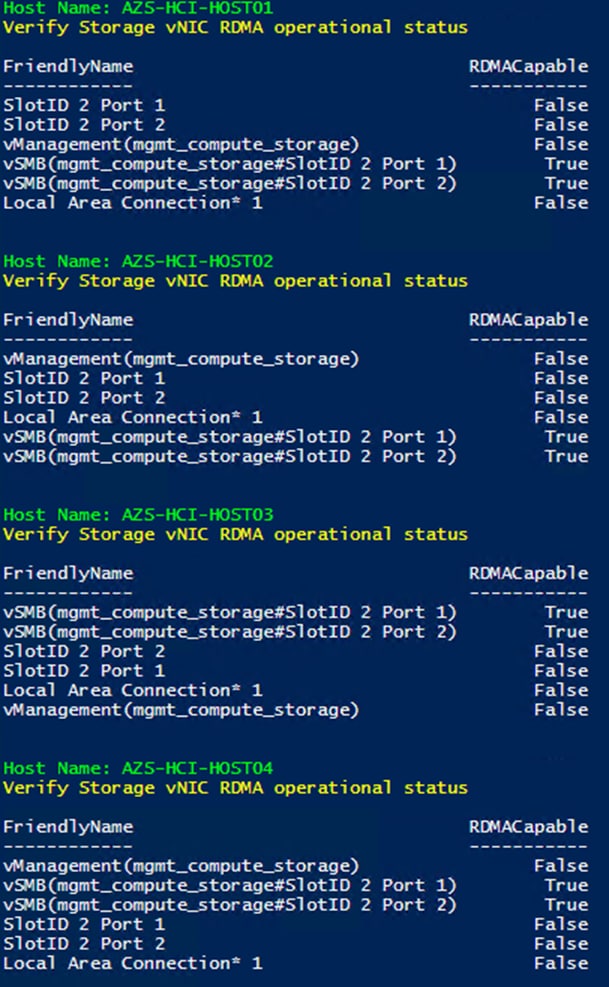
This subject has the following procedures:
● Verify Traffic Class Configuration on all Nodes
● Set DCBX Not Willing Mode on all Nodes
Procedure 1. Verify Traffic Class Configuration on all Nodes
Step 1. Run the following:
$nodes = ("AzS-HCI-Host01", "AzS-HCI-Host02", "AzS-HCI-Host03", "AzS-HCI-Host04")
foreach ($node in $nodes) {
Invoke-Command $node -Credential $Creds -scriptblock {
write-host "Host Name:" $env:COMPUTERNAME -ForegroundColor Green
Write-Host " Verifing Traffic Class Configuration " -ForegroundColor Yellow
Get-NetQosTrafficClass | ft -AutoSize
}
}
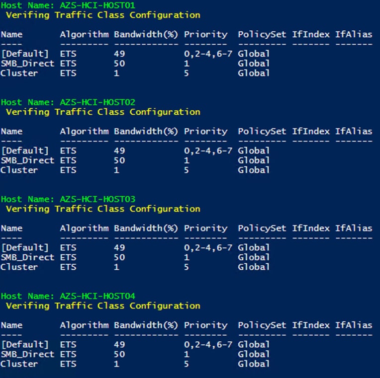
Procedure 2. Set DCBX Not Willing Mode on all Nodes
Step 1. Run the following:
Note: Server nodes need to be in Willing mode in order for DCBX auto negotiation to take place and Priority Flow Control to be enabled on the fabric interconnects ports. Priority Flow Control will not be enabled on the fabric interconnect server ports if the server DCBX Willing mode is set to false.
$nodes = ("AzS-HCI-Host01", "AzS-HCI-Host02", "AzS-HCI-Host03", "AzS-HCI-Host04")
foreach ($node in $nodes) {
Invoke-Command $node -Credential $Creds -scriptblock {
write-host "Host Name:" $env:COMPUTERNAME -ForegroundColor Green
Write-Host "Verifying that DCBX is set to Not Willing mode" -ForegroundColor Yellow
Get-netadapter | Get-NetQosDcbxSetting | ft InterfaceAlias, PolicySet, Willing
}
}
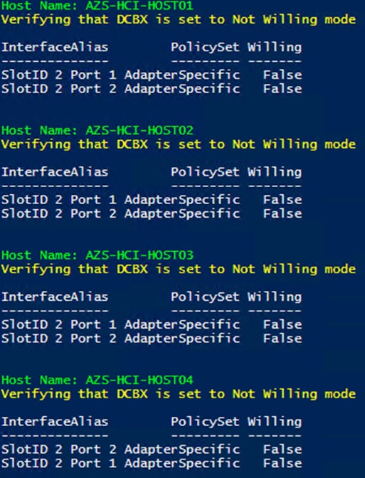
Prepare Server for Storage Spaces Direct
This subject contains the following procedures:
● Clean Inventory Storage Drives that will be used by Storage Spaces Direct
● Verify the Servers are ready for Storage Spaces Direct
Procedure 1. Run Windows Updated
IMPORTANT! It is extremely important to install the latest updated for Failover Cluster, Scale-Out Files Server, and Storage Spaces. Run Windows Update to install the latest updates after installing the Windows Features.
Note: The Cluster-Aware Updating role will be installed after the cluster is created. The cluster-aware updating is a feature that automates downloading and installing Windows Server updates on all cluster nodes.
Procedure 2. Clean Inventory Storage Drives that will be used by Storage Spaces Direct
Step 1. Run the following:
$nodes = ("AzS-HCI-Host01", "AzS-HCI-Host02", "AzS-HCI-Host03", "AzS-HCI-Host04")
foreach ($node in $nodes) {
Invoke-Command $node -Credential $Creds -scriptblock {
write-host "Host Name:" $env:COMPUTERNAME -ForegroundColor Green
Write-Host "Preparing disk for Storage Spaces Direct" -ForegroundColor Yellow
Write-Host Cleaning Storage Drives....
#Remove Exisiting virtual disks and storage pools
Update-StorageProviderCache
Get-StoragePool | ? IsPrimordial -eq $false | Set-StoragePool -IsReadOnly:$false -ErrorAction SilentlyContinue
Get-StoragePool | ? IsPrimordial -eq $false | Get-VirtualDisk | Remove-VirtualDisk -Confirm:$false -ErrorAction SilentlyContinue
Get-StoragePool | ? IsPrimordial -eq $false | Remove-StoragePool -Confirm:$false -ErrorAction SilentlyContinue
Get-PhysicalDisk | Reset-PhysicalDisk -ErrorAction SilentlyContinue
Get-Disk | ? Number -ne $null | ? IsBoot -ne $true | ? IsSystem -ne $true | ? PartitionStyle -ne RAW | % {
$_ | Set-Disk -isoffline:$false
$_ | Set-Disk -isreadonly:$false
$_ | Clear-Disk -RemoveData -RemoveOEM -Confirm:$false
$_ | Set-Disk -isreadonly:$true
$_ | Set-Disk -isoffline:$true
}
#Inventory Storage Disks
Get-Disk | Where Number -Ne $Null | Where IsBoot -Ne $True | Where IsSystem -Ne $True | Where PartitionStyle -Eq RAW | Group -NoElement -Property FriendlyName | ft
}
}
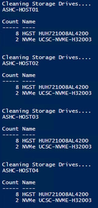
Procedure 3. Verify the Servers are ready for Storage Spaces Direct
Step 1. Run the following:
$CandidateClusterNode = "AzS-HCI-Host01"
Invoke-Command $CandidateClusterNode -Credential $Creds -scriptblock {
write-host "Host Name:" $env:COMPUTERNAME -ForegroundColor Green
Write-Host " Enabling CredSSP" -ForegroundColor Yellow
$Void = Enable-WSManCredSSP -Role Server -Force
}
Invoke-Command $CandidateClusterNode -Credential $Creds -authentication Credssp -scriptblock {
write-host "Host Name:" $env:COMPUTERNAME -ForegroundColor Green
$nodes = ("AzS-HCI-Host01", "AzS-HCI-Host02", "AzS-HCI-Host03", "AzS-HCI-Host04")
Write-Host " Validating Cluster Nodes..." -ForegroundColor Yellow
Test-Cluster -Node $nodes -Include "System Configuration",Networking,Inventory, “Storage Spaces Direct”
Write-Host " Disabling CredSSP" -ForegroundColor Yellow
Disable-WSManCredSSP -Role Server
Write-Host " Verifying that CredSSP are disabled on target server..." -ForegroundColor Yellow
Get-WSManCredSSP
}
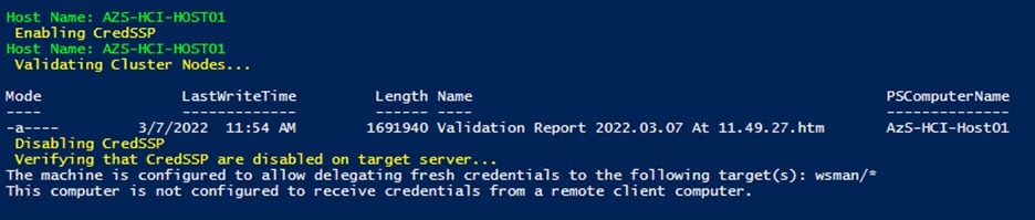
Step 2. Review the validation report and resolve all errors and warning before proceeding to create the Storage Spaces Direct Cluster:
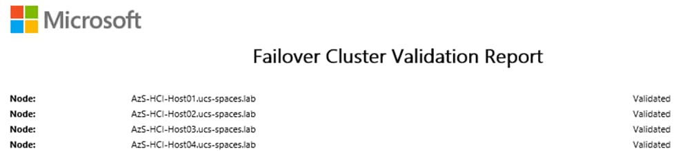
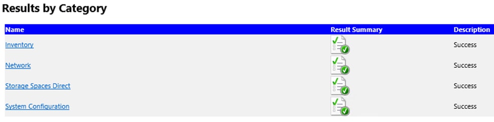
Configure Windows Failover Cluster
This subject contains the following procedures:
● Verify Status for Cluster Nodes after creating the Cluster
● Remove Standalone Network ATC Intent
● Create and Deploy Clustered Network ATC Intent
● Verify Clustered Network ATC Deployment and Status
● Verify Network Adapter Status after Network Intent Has Been Applied
● Verify Cluster Network Interfaces
● Configure Live Migration Network Isolation
● Get Management Cluster Network ID
● Exclude Management Network from Live Migration Network list
● Verify Live Migration Exclusion list
● Configure Live Migration to use SMB Protocol
● Configure Live Migration Bandwidth Limit
● Create Maximum Bandwidth Limit for Management vNIC
● Create the File Share for the Cluster Witness
● Configure File Share Witness
● Additional Cluster Quorum Witness Options
● Configure Cluster-Aware Updating
● Configure Kernel Soft Reboot for Cluster Aware Updating
Procedure 1. Create the Cluster
Step 1. Create the cluster with a static IP Address:
$CandidateClusterNode = "AzS-HCI-Host01"
Invoke-Command $CandidateClusterNode -Credential $Creds -scriptblock {
write-host "Host Name:" $env:COMPUTERNAME -ForegroundColor Green
Write-Host " Enabling CredSSP" -ForegroundColor Yellow
$Void = Enable-WSManCredSSP -Role Server -Force
}
Invoke-Command $CandidateClusterNode -Credential $Creds -authentication Credssp -scriptblock {
write-host "Host Name:" $env:COMPUTERNAME -ForegroundColor Green
$nodes = ("AzS-HCI-Host01", "AzS-HCI-Host02", "AzS-HCI-Host03", "AzS-HCI-Host04")
Write-Host " Creating the cluster..." -ForegroundColor Yellow
$Cluster = “AzS-HCI-C01”
New-Cluster -Name $Cluster -Node $nodes -StaticAddress 192.168.100.70 –NoStorage
Get-Cluster | fl Name, SharedVolumesRoot
Write-Host " Disabling CredSSP" -ForegroundColor Yellow
Disable-WSManCredSSP -Role Server
Write-Host " Verifying that CredSSP are disabled on target server..." -ForegroundColor Yellow
Get-WSManCredSSP
}
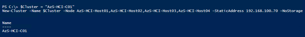
Procedure 2. Verify Status for Cluster Nodes after creating the Cluster
Step 1. Run the following:
$Cluster = “AzS-HCI-C01”
Get-ClusterNode -Cluster $Cluster
Invoke-Command $Cluster -Credential $Creds -scriptblock {
write-host "Host Name:" $env:COMPUTERNAME -ForegroundColor Green
Write-Host " Enabling CredSSP" -ForegroundColor Yellow
$Void = Enable-WSManCredSSP -Role Server -Force
}
Invoke-Command $Cluster -Credential $Creds -authentication Credssp -scriptblock {
$Cluster = “AzS-HCI-C01”
write-host "Host Name:" $env:COMPUTERNAME -ForegroundColor Green
Write-Host " Checking cluster nodes..." -ForegroundColor Yellow
Get-ClusterNode -Cluster $Cluster | ft Name, State, Type
Write-Host " Disabling CredSSP" -ForegroundColor Yellow
Disable-WSManCredSSP -Role Server
Write-Host " Verifying that CredSSP are disabled on target server..." -ForegroundColor Yellow
Get-WSManCredSSP
}
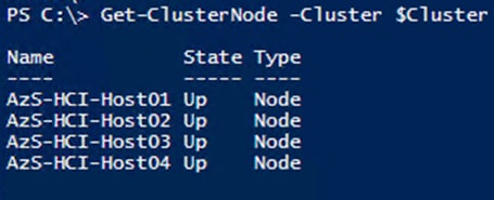
Procedure 3. Remove Standalone Network ATC Intent
Step 1. Run the following:
$Cluster = “AzS-HCI-C01”
$nodes = (Get-ClusterNode -Cluster $Cluster).Name
foreach ($node in $nodes) {
Invoke-Command $node -scriptblock {
write-host "Host Name:" $env:COMPUTERNAME -ForegroundColor Green
Write-Host " Identifying and Removing Standalone Network ATC Intent " -ForegroundColor Yellow
$intent = Get-NetIntent | Where-Object {$_.Scope -Like 'Host' -and $_.IntentName -EQ 'mgmt_compute_storage'}
Write-Host "Removing Standalone Network ATC Intent $intent" -ForegroundColor Yellow
Remove-NetIntent -Name $intent.IntentName
}
}
Procedure 4. Create and Deploy Clustered Network ATC Intent
Step 1. Run the following:
$Cluster = “AzS-HCI-C01”
Invoke-Command $Cluster -Credential $Creds -scriptblock {
write-host "Host Name:" $env:COMPUTERNAME -ForegroundColor Green
Write-Host " Enabling CredSSP" -ForegroundColor Yellow
$Void = Enable-WSManCredSSP -Role Server -Force
}
Invoke-Command $Cluster -Credential $Creds -authentication Credssp -scriptblock {
write-host "Host Name:" $env:COMPUTERNAME -ForegroundColor Green
Write-Host " Create and Deploy Clustered Network ATC Intent " -ForegroundColor Yellow
$QoSOverride = New-NetIntentQoSPolicyOverRides
$AdapterOverride = New-NetIntentAdapterPropertyOverrides
$QoSOverride.PriorityValue8021Action_SMB = 1
$QoSOverride.PriorityValue8021Action_Cluster = 5
$AdapterOverride.NetworkDirectTechnology = 4
$QoSOverride
$AdapterOverride
Add-NetIntent -AdapterName "SlotID 2 Port 1", "SlotID 2 Port 2" -Management -Compute -Storage -StorageVlans 107, 207 -QoSPolicyOverrides $QoSOverride -AdapterPropertyOverrides $AdapterOverride -Name Mgmt_Compute_Storage -ClusterName $ClusterName.Name
Write-Host " Disabling CredSSP" -ForegroundColor Yellow
Disable-WSManCredSSP -Role Server
Write-Host " Verifying that CredSSP are disabled on target server..." -ForegroundColor Yellow
Get-WSManCredSSP
}
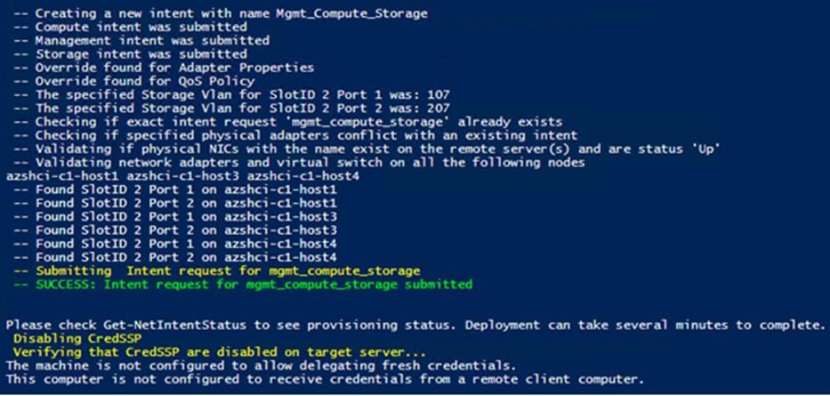
Procedure 5. Verify Clustered Network ATC Deployment and Status
Step 1. Run the following:
Invoke-Command $Cluster -Credential $Creds -scriptblock {
write-host "Host Name:" $env:COMPUTERNAME -ForegroundColor Green
Write-Host " Enabling CredSSP" -ForegroundColor Yellow
$Void = Enable-WSManCredSSP -Role Server -Force
}
Invoke-Command $Cluster -Credential $Creds -authentication Credssp -scriptblock {
write-host "Host Name:" $env:COMPUTERNAME -ForegroundColor Green
Write-Host " Verify Clustered Network ATC Intent Status " -ForegroundColor Yellow
$ClusterName = (Get-cluster).Name
Get-NetIntent -ClusterName $ClusterName| Select IntentName,scope
Get-NetIntentStatus -ClusterName $ClusterName | Select Host, IntentName, ConfigurationStatus, ProvisioningStatus
Write-Host " Disabling CredSSP" -ForegroundColor Yellow
Disable-WSManCredSSP -Role Server
Write-Host " Verifying that CredSSP are disabled on target server..." -ForegroundColor Yellow
Get-WSManCredSSP
}
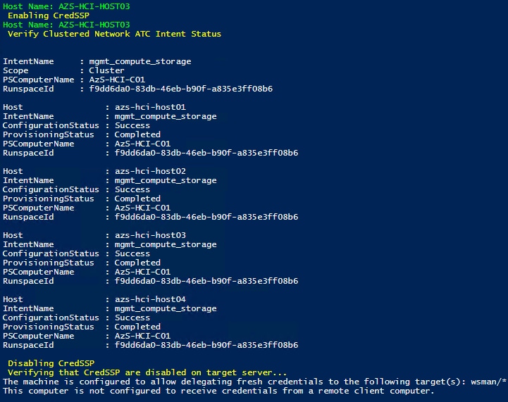
Note: It may take a few minutes for the network intent application to complete.
Procedure 6. Verify Network Adapter Status after Network Intent Has Been Applied
$nodes = (Get-ClusterNode -Cluster $Cluster).Name
foreach ($node in $nodes) {
Invoke-Command $node -Credential $Creds -scriptblock {
write-host "Host Name:" $env:COMPUTERNAME -ForegroundColor Green
Write-Host " Enabling CredSSP" -ForegroundColor Yellow
$Void = Enable-WSManCredSSP -Role Server -Force
Write-Host "Verifying NIC Port Status " -ForegroundColor Yellow
Get-netadapter | ft Name, InterfaceDescription, Status, MTUSize, MacAddress, LinkSpeed
Write-Host " Disabling CredSSP" -ForegroundColor Yellow
Disable-WSManCredSSP -Role Server
Write-Host " Verifying that CredSSP are disabled on target server..." -ForegroundColor Yellow
Get-WSManCredSSP
}
}
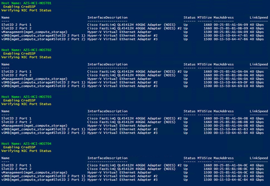
Procedure 7. Rename Cluster Networks
Step 1. Check cluster networks:
$Cluster = “AzS-HCI-C01”
Invoke-Command $Cluster -Credential $Creds -scriptblock {
write-host "Host Name:" $env:COMPUTERNAME -ForegroundColor Green
Write-Host " Enabling CredSSP" -ForegroundColor Yellow
$Void = Enable-WSManCredSSP -Role Server -Force
}
Invoke-Command $Cluster -Credential $Creds -authentication Credssp -scriptblock {
write-host "Host Name:" $env:COMPUTERNAME -ForegroundColor Green
Write-Host " Checking cluster networks " -ForegroundColor Yellow
$ClusterName = (Get-cluster).Name
Get-ClusterNetwork -Cluster $ClusterName | ft name,address,state,role –autosize
Write-Host " Disabling CredSSP" -ForegroundColor Yellow
Disable-WSManCredSSP -Role Server
Write-Host " Verifying that CredSSP are disabled on target server..." -ForegroundColor Yellow
Get-WSManCredSSP
}
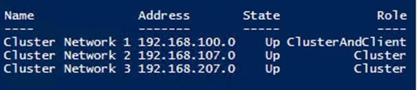
Procedure 8. Rename the Cluster Networks
Step 1. Run the following:
$Cluster = “AzS-HCI-C01”
Invoke-Command $Cluster -Credential $Creds -scriptblock {
write-host "Host Name:" $env:COMPUTERNAME -ForegroundColor Green
Write-Host " Enabling CredSSP" -ForegroundColor Yellow
$Void = Enable-WSManCredSSP -Role Server -Force
}
Invoke-Command $Cluster -Credential $Creds -authentication Credssp -scriptblock {
write-host "Host Name:" $env:COMPUTERNAME -ForegroundColor Green
Write-Host " Renaming cluster networks " -ForegroundColor Yellow
$ClusterName = (Get-cluster).Name
(Get-ClusterNetwork -Cluster $ClusterName "Cluster Network 1").Name="Management"
(Get-ClusterNetwork -Cluster $ClusterName "Cluster Network 2").Name="Storage_A"
(Get-ClusterNetwork -Cluster $ClusterName "Cluster Network 3").Name="Storage_B"
Get-ClusterNetwork -Cluster $ClusterName | ft name,address,state,role –autosize
Write-Host " Disabling CredSSP" -ForegroundColor Yellow
Disable-WSManCredSSP -Role Server
Write-Host " Verifying that CredSSP are disabled on target server..." -ForegroundColor Yellow
Get-WSManCredSSP
}
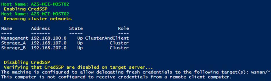
Procedure 9. Verify Cluster Network Interfaces
Step 1. Run the following:
$Cluster = “AzS-HCI-C01”
Invoke-Command $Cluster -Credential $Creds -scriptblock {
write-host "Host Name:" $env:COMPUTERNAME -ForegroundColor Green
Write-Host " Enabling CredSSP" -ForegroundColor Yellow
$Void = Enable-WSManCredSSP -Role Server -Force
}
Invoke-Command $Cluster -Credential $Creds -authentication Credssp -scriptblock {
write-host "Host Name:" $env:COMPUTERNAME -ForegroundColor Green
Write-Host " Verifying cluster network interfaces " -ForegroundColor Yellow
$ClusterName = (Get-cluster).Name
Get-ClusterNetworkInterface -Cluster $ClusterName | sort Name | ft Network, Name
Write-Host " Disabling CredSSP" -ForegroundColor Yellow
Disable-WSManCredSSP -Role Server
Write-Host " Verifying that CredSSP are disabled on target server..." -ForegroundColor Yellow
Get-WSManCredSSP
}
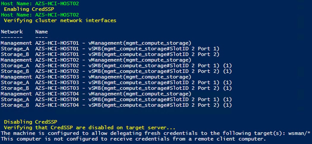
Procedure 10. Configure Live Migration Network Isolation
Step 1. Check initial Live Migration Network Settings:
$Cluster = “AzS-HCI-C01”
Invoke-Command $Cluster -Credential $Creds -scriptblock {
write-host "Host Name:" $env:COMPUTERNAME -ForegroundColor Green
Write-Host " Enabling CredSSP" -ForegroundColor Yellow
$Void = Enable-WSManCredSSP -Role Server -Force
}
Invoke-Command $Cluster -Credential $Creds -authentication Credssp -scriptblock {
write-host "Host Name:" $env:COMPUTERNAME -ForegroundColor Green
Write-Host " Checking Live Migration network settings " -ForegroundColor Yellow
$ClusterName = (Get-cluster).Name
Get-ClusterResourceType -Cluster $ClusterName -Name "Virtual Machine" | Get-ClusterParameter -Name MigrationExcludeNetworks | fl *
Write-Host " Disabling CredSSP" -ForegroundColor Yellow
Disable-WSManCredSSP -Role Server
Write-Host " Verifying that CredSSP are disabled on target server..." -ForegroundColor Yellow
Get-WSManCredSSP
}
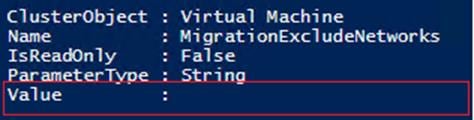
Procedure 11. Get Management Cluster Network ID
Step 1. Run the following:
$Cluster = “AzS-HCI-C01”
Invoke-Command $Cluster -Credential $Creds -scriptblock {
write-host "Host Name:" $env:COMPUTERNAME -ForegroundColor Green
Write-Host " Enabling CredSSP" -ForegroundColor Yellow
$Void = Enable-WSManCredSSP -Role Server -Force
}
Invoke-Command $Cluster -Credential $Creds -authentication Credssp -scriptblock {
write-host "Host Name:" $env:COMPUTERNAME -ForegroundColor Green
Write-Host " Checking Management cluster network settings " -ForegroundColor Yellow
$ClusterName = (Get-cluster).Name
Get-ClusterNetwork -Cluster $ClusterName -Name Management | fl *
Write-Host " Disabling CredSSP" -ForegroundColor Yellow
Disable-WSManCredSSP -Role Server
Write-Host " Verifying that CredSSP are disabled on target server..." -ForegroundColor Yellow
Get-WSManCredSSP
}
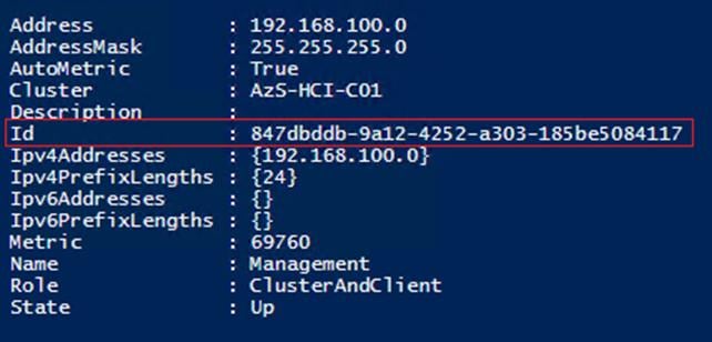
Procedure 12. Exclude Management Network from Live Migration Network list
Step 1. Run the following:
$Cluster = “AzS-HCI-C01”
Invoke-Command $Cluster -Credential $Creds -scriptblock {
write-host "Host Name:" $env:COMPUTERNAME -ForegroundColor Green
Write-Host " Enabling CredSSP" -ForegroundColor Yellow
$Void = Enable-WSManCredSSP -Role Server -Force
}
Invoke-Command $Cluster -Credential $Creds -authentication Credssp -scriptblock {
write-host "Host Name:" $env:COMPUTERNAME -ForegroundColor Green
Write-Host " Excluding Management network from Live Migration Network list " -ForegroundColor Yellow
$ClusterName = (Get-cluster).Name
Get-ClusterResourceType -Cluster $ClusterName -Name "Virtual Machine" | Set-ClusterParameter -Cluster $ClusterName -Name MigrationExcludeNetworks -Value ([String]::Join(";",(Get-ClusterNetwork -Cluster $ClusterName | Where-Object {$_.Name -eq "Management"}).ID))
Write-Host " Disabling CredSSP" -ForegroundColor Yellow
Disable-WSManCredSSP -Role Server
Write-Host " Verifying that CredSSP are disabled on target server..." -ForegroundColor Yellow
Get-WSManCredSSP
}
Procedure 13. Verify Live Migration Exclusion list
Step 1. Run the following:
$Cluster = “AzS-HCI-C01”
Invoke-Command $Cluster -Credential $Creds -scriptblock {
write-host "Host Name:" $env:COMPUTERNAME -ForegroundColor Green
Write-Host " Enabling CredSSP" -ForegroundColor Yellow
$Void = Enable-WSManCredSSP -Role Server -Force
}
Invoke-Command $Cluster -Credential $Creds -authentication Credssp -scriptblock {
write-host "Host Name:" $env:COMPUTERNAME -ForegroundColor Green
Write-Host " Verifying Management network exclusion from Live Migration Network list " -ForegroundColor Yellow
$ClusterName = (Get-cluster).Name
Get-ClusterResourceType -Cluster $ClusterName -Name "Virtual Machine" | Get-ClusterParameter -Cluster $ClusterName -Name MigrationExcludeNetworks | fl *
Write-Host " Disabling CredSSP" -ForegroundColor Yellow
Disable-WSManCredSSP -Role Server
Write-Host " Verifying that CredSSP are disabled on target server..." -ForegroundColor Yellow
Get-WSManCredSSP
}
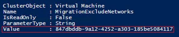
For more information, go to: https://technet.microsoft.com/en-us/library/dn550728(v=ws.11).aspx
Procedure 14. Configure Live Migration to use SMB Protocol
Note: SMB protocol provides the best throughput for Live Migration. The default setting is Compression which is best for constrained networks.
Step 1. Run the following:
$Cluster = “AzS-HCI-C01”
$nodes = (Get-ClusterNode -Cluster $Cluster).Name
foreach ($node in $nodes) {
Invoke-Command $node -scriptblock {
write-host "Host Name:" $env:COMPUTERNAME -ForegroundColor Green
Write-Host "Configuring Live Migration to use SMB protocol" -ForegroundColor Yellow
Set-VMHost -VirtualMachineMigrationPerformanceOption SMB
Get-VMHost | fl VirtualMachineMigrationPerformanceOption
}
}
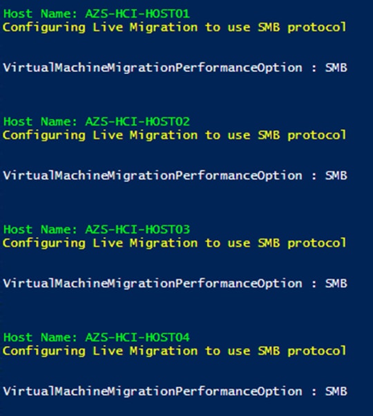
Procedure 15. Configure Live Migration Bandwidth Limit
Note: SMB Direct is allocated 50% of the link speed bandwidth. The following configuration parameter limits SMB Direct bandwidth allowed for Live Migration to 29%. The remaining SMB Direct bandwidth is allocated to Storage Bus Layer and Cluster Shared Volume network traffic.
Step 1. Run the following:
$nodes = (Get-ClusterNode -Cluster $Cluster).Name
foreach ($node in $nodes) {
Invoke-Command $node -scriptblock {
write-host "Host Name:" $env:COMPUTERNAME -ForegroundColor Green
Write-Host "Configuring Live Migration Bandwidth Limit: 1485MB" -ForegroundColor Yellow
Set-SMBBandwidthLimit -Category LiveMigration -BytesPerSecond 1485MB
Get-SMBBandwidthLimit -Category LiveMigration
}
}
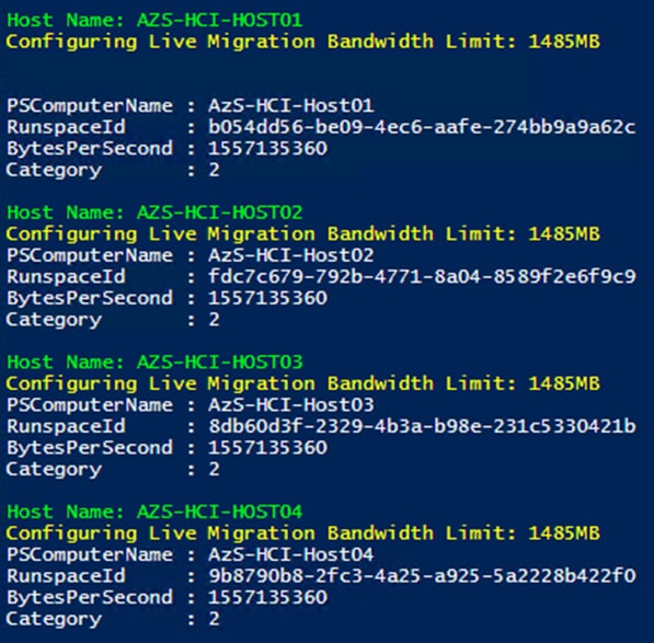
Procedure 16. Create Maximum Bandwidth Limit for Management vNIC
Note: This is an optional configuration item that limits the network bandwidth to the management vNIC. The management vNIC shares total bandwidth with the bandwidth allocated to tenant network traffic. The allocated tenant network traffic bandwidth is 50% of the total bandwidth. The following configuration example sets the maximum bandwidth limit 4Gb/s (10% of the tenant network traffic bandwidth) for the management vNIC . This value can be adjusted as needed.
$nodes = (Get-ClusterNode -Cluster $Cluster).Name
foreach ($node in $nodes) {
Invoke-Command $node -scriptblock {
$MgmtBandwidthLimit = "4000000"
write-host "Host Name:" $env:COMPUTERNAME -ForegroundColor Green
Write-Host "Configuring management vNIC maximum bandwidth Limit: $MgmtBandwidthLimit" -ForegroundColor Yellow
Set-VMNetworkAdapter -ManagementOS -Name "vManagement(mgmt_compute_storage)" -MaximumBandwidth $MgmtBandwidthLimit
Write-Host "Verifying management vNIC maximum bandwidth Limit" -ForegroundColor Yellow
(Get-VMNetworkAdapter -ManagementOS -Name "vManagement(mgmt_compute_storage)").BandwidthSetting | ft ParentAdapter, MaximumBandwidth
}
}
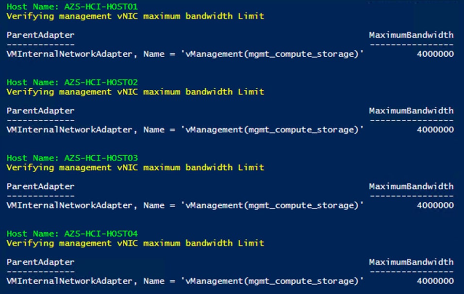
Procedure 17. Create the File Share for the Cluster Witness
Step 1. Run the following commands:
Note: These commands require the files share witness server to be a domain member. It’s recommended that the witness share is placed on a highly available scale out file server. The “-ContinuouslyAvailable” command option should be used when creating a share on a highly available scale out file server.
$FSW = “fsw01.ucs-spaces.lab”
$FSWDomain = “ucs-spaces.lab”
$ShareName = "FSW-AzS-HCI-C01"
$SharePath = "C:\FileShareWitness\FSW-AzS-HCI-C01"
Invoke-Command -ComputerName $FSW -ScriptBlock {
#Create Directory on File Share Witness
Write-Host "Creating directory on files share witness"
mkdir $Using:SharePath
#Create file share on the file share witness
Write-Host "Creating file share on file share witness"
new-smbshare -Name $Using:ShareName -Path $Using:SharePath -FullAccess “ucs-spaces.lab\Domain Admins", "ucs-spaces.lab\AzS-HCI-C01$", "ucs-spaces.lab\AzS-HCI-Host01$”, "ucs-spaces.lab\AzS-HCI-Host02$”, "ucs-spaces.lab\AzS-HCI-Host03$”, "ucs-spaces.lab\AzS-HCI-Host04$”
#Verify file share on file share witness
Write-Host "Verifying file share on file share witness"
Get-SmbShare -Name $Using:ShareName | ft name,path -AutoSize
#Verify file share permissions on the file share witness
Write-Host "Verifing file share permissions on the file share witness"
Get-SmbShareAccess -Name $Using:ShareName | ft –AutoSize
#Set file level permissions on the file share directory that match the file share permissions
Write-Host "Setting file level permissions on the file share directory that match the file share permissions"
Set-SmbPathAcl -ShareName $Using:ShareName
#Verify file level permissions on the file share
Write-Host "Verifying file level permissions on the file share"
Get-Acl -Path $Using:SharePath | fl
}
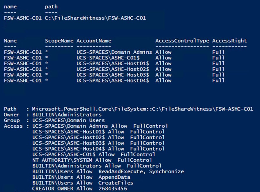
Procedure 18. Configure File Share Witness
Step 1. Run the following:
$Cluster = “AzS-HCI-C01”
$FSW = “fsw01.ucs-spaces.lab”
$ShareName = "FSW-AzS-HCI-C01"
Set-ClusterQuorum -Cluster $Cluster -FileShareWitness \\$FSW\$ShareName
Procedure 19. Verify File Share Witness Path
Step 1. Run the following:
$Cluster = “AzS-HCI-C01”
Get-ClusterResource -Cluster $Cluster -Name "File Share Witness" | Get-ClusterParameter -Name SharePath
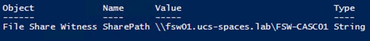
Procedure 20. Additional Cluster Quorum Witness Options
Note: Cloud Witness and none domain join files share witness can be implemented as alternate cluster witness options. Implementation details for these options can be found that the following links:
https://docs.microsoft.com/en-us/windows-server/failover-clustering/deploy-cloud-witness
Procedure 21. Configure Cluster-Aware Updating
Note: The Cluster-Aware Updating role will be installed after the cluster is created. The cluster-aware updating is a feature that automates downloading and installing Windows Server updates on all cluster nodes.
Please see the documentation at the following link for further Cluster-Aware Updating details: https://docs.microsoft.com/en-us/windows-server/failover-clustering/cluster-aware-updating
Step 1. Run the following commands to configure Cluster-Aware Updating:
$Cluster = “AzS-HCI-C01”
Invoke-Command $Cluster -Credential $Creds -scriptblock {
write-host "Host Name:" $env:COMPUTERNAME -ForegroundColor Green
Write-Host " Enabling CredSSP" -ForegroundColor Yellow
$Void = Enable-WSManCredSSP -Role Server -Force
}
Invoke-Command $Cluster -Credential $Creds -authentication Credssp -scriptblock {
write-host "Host Name:" $env:COMPUTERNAME -ForegroundColor Green
Write-Host " Configuring Cluster-Aware Updating ... " -ForegroundColor Yellow
$ClusterName = (Get-cluster).Name
Add-CauClusterRole -ClusterName $ClusterName -DaysOfWeek Tuesday,Saturday -IntervalWeeks 3 -MaxFailedNodes 1 -MaxRetriesPerNode 2 -EnableFirewallRules -Force
Write-Host " Verifying Cluster-Aware Updating configuraiton " -ForegroundColor Yellow
Get-CauClusterRole -ClusterName $ClusterName | ft
Write-Host " Disabling CredSSP" -ForegroundColor Yellow
Disable-WSManCredSSP -Role Server
Write-Host " Verifying that CredSSP are disabled on target server..." -ForegroundColor Yellow
Get-WSManCredSSP
}
Note: This process might take several minutes.
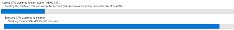
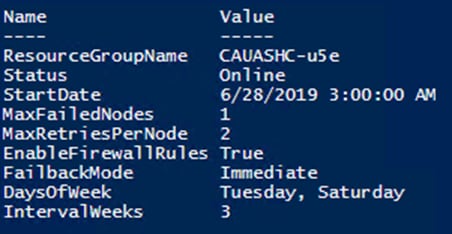
Procedure 22. Configure Kernel Soft Reboot for Cluster Aware Updating
Note: Kernel Soft Reboot reduces the time required to reboot a server by bypassing BIOS and firmware initiation. Kernel Soft Reboot works with Cluster Aware Updating for applying software updates. Kernel Soft Reboot cannot be used to the server when BIOS and firmware updates need to be applied.
Step 1. Run the following:
$Cluster = “AzS-HCI-C01”
Invoke-Command $Cluster -Credential $Creds -scriptblock {
write-host "Host Name:" $env:COMPUTERNAME -ForegroundColor Green
Write-Host " Enabling CredSSP" -ForegroundColor Yellow
$Void = Enable-WSManCredSSP -Role Server -Force
}
Invoke-Command $Cluster -Credential $Creds -authentication Credssp -scriptblock {
write-host "Host Name:" $env:COMPUTERNAME -ForegroundColor Green
$ClusterName = (Get-cluster).Name
Write-Host " Configuring Kernel Soft Reboot for Cluster Aware Updating ... " -ForegroundColor Yellow
Get-Cluster -Name $ClusterName | Set-ClusterParameter -Name CauEnableSoftReboot -Value 1 -Create
Write-Host " Verifying Kernel Soft Reboot configuraiton " -ForegroundColor Yellow
Get-Cluster -Name $ClusterName | Get-ClusterParameter -Name CauEnableSoftReboot | ft Name, Value
Write-Host " Disabling CredSSP" -ForegroundColor Yellow
Disable-WSManCredSSP -Role Server
Write-Host " Verifying that CredSSP are disabled on target server..." -ForegroundColor Yellow
Get-WSManCredSSP
}
Configure Storage Spaces Direct
This subject contains the following procedures:
● Enable Storage Spaces Direct
● Verify the newly created Storage Pool, NVMe SSD Cache, and Storage Tiers
● Create a Virtual Disk with Mirror Resiliency by using the Performance Tier template
● Register the Azure Stack HCI Cluster with Azure
● Create a Virtual Machine with Failover Capability
Procedure 1. Enable Storage Spaces Direct
The following command automatically enables Storage Spaces Direct and configures the following:
● Create a pool: Creates a single large pool that has a name like “S2D on Cluster1”.
● Configures the Storage Spaces Direct caches: If there is more than one media (drive) type available for Storage Spaces Direct use, it enables the fastest as cache devices (read and write in most cases).
● Tiers: Creates 2 tiers as default tiers. One is called “Capacity” and the other called “Performance”. The cmdlet analyzes the devices and configures each tier with the mix of device types and resiliency.
$Cluster = “AzS-HCI-C01”
Invoke-Command $Cluster -Credential $Creds -scriptblock {
write-host "Host Name:" $env:COMPUTERNAME -ForegroundColor Green
Write-Host " Enabling CredSSP" -ForegroundColor Yellow
$Void = Enable-WSManCredSSP -Role Server -Force
}
Invoke-Command $Cluster -Credential $Creds -authentication Credssp -scriptblock {
write-host "Host Name:" $env:COMPUTERNAME -ForegroundColor Green
$ClusterName = (Get-cluster).Name
Write-Host " Enabling Storage Spaces Direct " -ForegroundColor Yellow
Enable-ClusterStorageSpacesDirect -Confirm:$false
Write-Host " Disabling CredSSP" -ForegroundColor Yellow
Disable-WSManCredSSP -Role Server
Write-Host " Verifying that CredSSP are disabled on target server..." -ForegroundColor Yellow
Get-WSManCredSSP
}
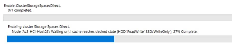
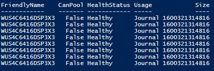
Procedure 2. Verify the newly created Storage Pool, NVMe SSD Cache, and Storage Tiers
Step 1. Run the following:
$Cluster = “AzS-HCI-C01”
Invoke-Command $Cluster -Credential $Creds -scriptblock {
write-host "Host Name:" $env:COMPUTERNAME -ForegroundColor Green
Write-Host " Enabling CredSSP" -ForegroundColor Yellow
$Void = Enable-WSManCredSSP -Role Server -Force
}
Invoke-Command $Cluster -Credential $Creds -authentication Credssp -scriptblock {
write-host "Host Name:" $env:COMPUTERNAME -ForegroundColor Green
$ClusterName = (Get-cluster).Name
Write-Host " Verifying Storage Pools " -ForegroundColor Yellow
Get-StoragePool | ft friendlyname, OperationalStatus, HealthStatus, IsPrimordial, IsReadonly
Write-Host " Verifying NVMe SSD Cache Tier " -ForegroundColor Yellow
Get-PhysicalDisk | ? Usage -eq "Journal" | ft FriendlyName, CanPool, HealthStatus, Usage, Size
Write-Host " Verifying Storage Tier configuration " -ForegroundColor Yellow
Get-storagetier | ft FriendlyName, ResiliencySettingName, MediaType, NumberOfDataCopies, PhysicalDiskRedundancy
Write-Host " Disabling CredSSP" -ForegroundColor Yellow
Disable-WSManCredSSP -Role Server
Write-Host " Verifying that CredSSP are disabled on target server..." -ForegroundColor Yellow
Get-WSManCredSSP
}
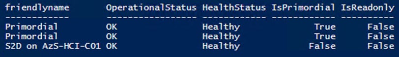

Figure 15. Storage tier with hard drives
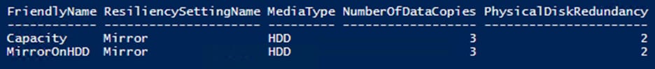
Figure 16. Storage tier with SATA SSDs
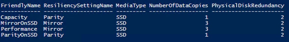
Procedure 3. Create a Virtual Disk with Mirror Resiliency by using the Performance Tier template
It is optimal to create a virtual disk in multiples that match the number of cluster nodes that will run virtual machines. For example, the number of virtual disks for cluster with 4 nodes should b 4, 8, 12, and so on.
Note: The following link contains Microsoft recommendations for volume capacity planning:
https://docs.microsoft.com/en-us/azure-stack/hci/concepts/plan-volumes
The New-Volume cmdlet simplifies deployments as it ties together a long list of operations that would otherwise have to be done in individual commands such as creating the virtual disk, partitioning and formatting the virtual disk, adding the virtual disk to the cluster, and converting it into CSVFS.
Step 1. Run the following command to create the multiple times. Update the Virtual Disk friendly name and size as required:
$Cluster = “AzS-HCI-C01”
Invoke-Command $Cluster -Credential $Creds -scriptblock {
write-host "Host Name:" $env:COMPUTERNAME -ForegroundColor Green
Write-Host " Enabling CredSSP" -ForegroundColor Yellow
$Void = Enable-WSManCredSSP -Role Server -Force
}
Invoke-Command $Cluster -Credential $Creds -authentication Credssp -scriptblock {
write-host "Host Name:" $env:COMPUTERNAME -ForegroundColor Green
$ClusterName = (Get-cluster).Name
Write-Host " Creating Virtual Disk " -ForegroundColor Yellow
New-Volume -StoragePoolFriendlyName “S2D*” -FriendlyName VDisk01 -FileSystem CSVFS_ReFS -ResiliencySettingName Mirror -Size 4TB
Write-Host " Disabling CredSSP" -ForegroundColor Yellow
Disable-WSManCredSSP -Role Server
Write-Host " Verifying that CredSSP are disabled on target server..." -ForegroundColor Yellow
Get-WSManCredSSP
}
$cluster = "AzS-HCI-C01"
Invoke-Command $cluster -scriptblock {New-Volume -StoragePoolFriendlyName “S2D*” -FriendlyName VDisk01 -FileSystem CSVFS_ReFS -ResiliencySettingName Mirror -Size 4TB}

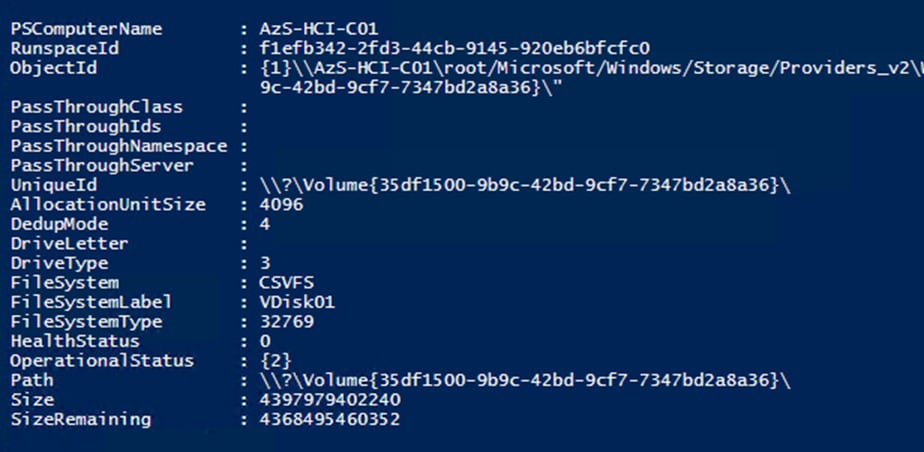
Step 2. The virtual disk status can be viewed by running the following command:
$cluster = "AzS-HCI-C01"
Invoke-Command $cluster -scriptblock {Get-VirtualDisk}
Run the following command to view the path of the new virtual disk:
$cluster = "AzS-HCI-C01"
Invoke-Command $cluster -scriptblock {Get-ClusterSharedVolume | fl Name,SharedVolumeInfo,OwnerNode}
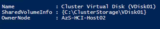
Note: The Cluster Shared Volume ownership can be realigned with the cluster nodes if desired. It is optimal when cluster virtual disk ownership id evenly distributed across the cluster nodes.
Procedure 4. Create Storage QoS Policy
Note: Storge QoS Policies limit the maximum IOPS that can be consumed by a virtual disk. These policies can prevent a “noisy neighbor” scenario where an individual virtual machine consumes an undesirable amount of storage IOPS and bandwidth, thus starving the available IOPS and bandwidth for other tenant virtual machines. The storage QoS policy is first created, and the policy ID is applied to a virtual disk (VHDX).
Step 1. The minimum and maximum IOPS values can be adjusted to as needed for the specific environment, by running the following command:
$Cluster = “AzS-HCI-C01”
Invoke-Command $Cluster -Credential $Creds -scriptblock {
write-host "Host Name:" $env:COMPUTERNAME -ForegroundColor Green
Write-Host " Creating and verifying Storage Polices" -ForegroundColor Yellow
New-StorageQoSPolicy -Name Copper -MinimumIops 50 -MaximumIops 100 -PolicyType Dedicated
New-StorageQoSPolicy -Name Bronze -MinimumIops 100 -MaximumIops 250 -PolicyType Dedicated
New-StorageQoSPolicy -Name Silver -MinimumIops 200 -MaximumIops 500 -PolicyType Dedicated
New-StorageQoSPolicy -Name Gold -MinimumIops 500 -MaximumIops 5000 -PolicyType Dedicated
New-StorageQoSPolicy -Name Platinum -MinimumIops 1000 -MaximumIops 10000 -PolicyType Dedicated
Get-StorageQoSPolicy | ft Name,Status, MinimumIops,MaximumIops,MaximumIOBandwidth,PolicyID
}
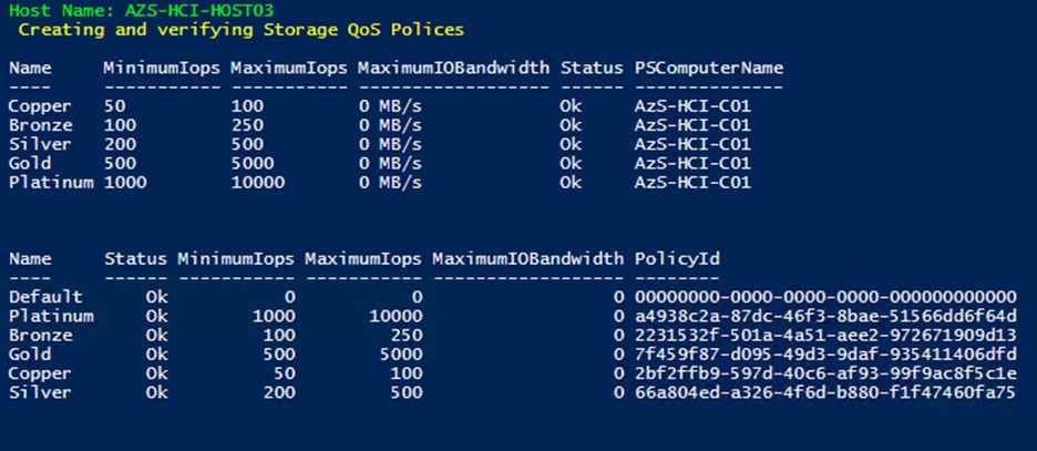
Note: The Maximum IOPS value is in units of 8KB-normalized. IO larger than 8KB is treated as multiple normalize IOPS. For example, 64KB IO is treated as 8 normalized IOPS.
Procedure 5. Register the Azure Stack HCI Cluster with Azure
Note: Follow the documentation at the following link to register the cluster with the Azure subscription. The registration must be completed successfully in order to create virtual machines in the Azure Stack HCI cluster: https://docs.microsoft.com/en-us/azure-stack/hci/deploy/register-with-azure
Procedure 6. Create a Virtual Machine with Failover Capability
Note: The following script is an example of creating a virtual machine with failover capability. This example includes creation of a VHDX file for the virtual machine with an attached storage QoS policy:
$Cluster = “AzS-HCI-C01”
Invoke-Command $Cluster -Credential $Creds -scriptblock {
write-host "Host Name:" $env:COMPUTERNAME -ForegroundColor Green
Write-Host " Enabling CredSSP" -ForegroundColor Yellow
$Void = Enable-WSManCredSSP -Role Server -Force
}
Invoke-Command $Cluster -Credential $Creds -authentication Credssp -scriptblock {
write-host "Host Name:" $env:COMPUTERNAME -ForegroundColor Green
$CSVPath = ((Get-ClusterSharedVolume).SharedVolumeInfo).FriendlyVolumeName
$VHDPath = "$CSVPath\VM01-Disk01.vhdx"
$VMSwitch = (Get-VMSwitch).Name
$VMName = "VM01"
$VMPath = "$CSVPath\VirtualMachines"
$VMMemoryCapacity = 8GB
Write-Host "Creating VHDX $VHDPath ..." -ForegroundColor Yellow
New-VHD -Path $CSVPath\VM01-Disk01.vhdx -Fixed -SizeBytes 100GB
Write-Host "Creating virtual machine $VMName with memory capacity $VMMemoryCapacity ... " -ForegroundColor Yellow
New-VM -Name $VMName -Path $VMPath -MemoryStartupBytes $VMMemoryCapacity -VHDPath $VHDPath -Generation 2 -SwitchName $VMSwitch
$BronzeStorageQoSPolicyID = (Get-StorageQosPolicy -Name Silver).PolicyId
Write-Host "Setting QoS Plicy for virtual machine $VMName ..." -ForegroundColor Yellow
Get-VM -VMName $VMName | Get-VMHardDiskDrive | Set-VMHardDiskDrive -QoSPolicyID $BronzeStorageQoSPolicyID
Write-Host "Clustering the virtual machine $VMName ..." -ForegroundColor Yellow
Get-VM -Name $VMName | Add-ClusterVirtualMachineRole -Name $VMName
Write-Host " Disabling CredSSP" -ForegroundColor Yellow
Disable-WSManCredSSP -Role Server
Write-Host " Verifying that CredSSP are disabled on target server..." -ForegroundColor Yellow
Get-WSManCredSSP
}
This chapter contains the following:
● Locate Windows Driver Required for Cisco UCS C240 M5 Server
● Add Drivers and Windows Updates to a Windows Installation Image
● Install and Configure DHCP Server Feature
● ToR Switch vPC Configuration
● HSRP with DHCP Relay Configuration Example
● Manual Cisco USC Manager Configuration
● Configure Fabric Interconnect Ports
● Create Service Profile Templates
● Create Autoconfiguration Policy
● Azure Stack HCI Firmware and Driver Update
Cluster-Aware Updating: https://docs.microsoft.com/en-us/windows-server/failover-clustering/cluster-aware-updating
Active Memory Dump: https://techcommunity.microsoft.com/t5/failover-clustering/windows-server-2016-failover-cluster-troubleshooting/ba-p/372008
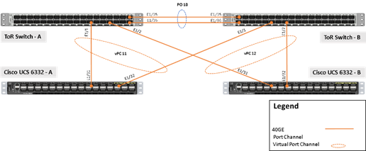
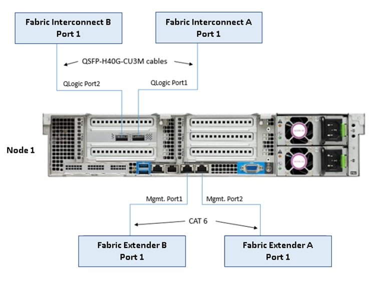
Required Widows Features are as follows:
● Clustering
● Hyper-V Management
● Group Policy Management
● Bitlocker Recovery Password Viewer
● Active Directory Management Tools
#Install required management modules
Add-WindowsFeature -Name RSAT-Hyper-V-Tools,RSAT-ADDS-Tools, RSAT-Clustering, RSAT-Clustering-MgmtRSAT-Clustering-PowerShell, RSAT-Feature-Tools-BitLocker-BdeAducExt,GPMC -IncludeManagementTools
Install-Module AZ.ConnectedMachine -force
#Update download provider modules for downloading modules from PSGallery
Set-PSRepository -Name "PSGallery" -InstallationPolicy Trusted
Install-PackageProvider -Name NuGet -Force
Install-Module -Name PowershellGet -Force -Confirm:$false
#Close and restart the PowerShell Windows before proceeding
#Configure WinRM for remote management of nodes
winrm quickconfig
#Enable sending remote management commands to the cluster nodes
$nodes = ("AzS-HCI-Host01", "AzS-HCI-Host02", "AzS-HCI-Host03", "AzS-HCI-Host04")
Enable-WSManCredSSP -Role "Client" -DelegateComputer $nodes
Locate Windows Driver Required for Cisco UCS C240 M5 Server
Drivers for the Azure Stack HCI hosts are provided at the Azure Stack HCI download portal Software Download - Cisco Systems.
Note: All drivers can be installed using PNPUtil.exe.
The drivers in the following folders need to be installed using PNPUtil or during the Azure Stack HCI 21H2 installation process that is executed using Azure Stack HCI 21H2 ISO distribution that is downloaded from the Microsoft Azure Stack HCI site:
● .\ChipSet\Skylake
● .\ChipSet\Skylake-E
● .\ChipSet\Lewisburg
● .\Network\QL45412H\EVBD
● .\Network\QL45412H\NDIS
● .\Storage\Embedded-RAID
The following PNPUtile.exe example can be used to install drivers:
pnputil /add-driver C:\temp\drivers \*.inf
PNPUtil.exe documentation can be found at the following link: https://docs.microsoft.com/en-us/windows-hardware/drivers/devtest/pnputil
Add Drivers and Windows Updates to a Windows Installation Image
A Windows ISO image includes boot.wim and install.wim files that are used for installation. The following are the PowerShell cmdlets to inject drivers into these .wim files.
● Get-WindowsImage
https://docs.microsoft.com/en-us/powershell/module/dism/get-windowsimage?view=win10-ps
● Mount-WindowsImage
https://docs.microsoft.com/en-us/powershell/module/dism/mount-windowsimage?view=win10-ps
● Add-WindowsDriver
https://docs.microsoft.com/en-us/powershell/module/dism/add-windowsdriver?view=win10-ps
● Dismount-WindowsImage
https://docs.microsoft.com/en-us/powershell/module/dism/dismount-windowsimage?view=win10-ps
Procedure 1. Prepare Driver Injection Computer
Step 1. Copy contents of Windows Server 2019 ISO distribution ISO, including boot.wim and install.wim, to a computer disk that will be used to inject the drivers.
Example:
Destination path = C:\temp\Source-ISO
Step 2. Copy required drivers into a subdirectory on the server. Each driver should have its own subdirectory. Each driver should include a .sys, .inf, and a .cat file at minimum. Drivers cannot be in a zip file or exe file. Chipset drivers need to be extracted prior to injection.
Example:
Destination path: C:\temp\drivers
Step 3. Create a subdirectory for mounting the target image.
Example:
md C:\temp\offline
Procedure 2. Inject Drivers into boot.wim Images
Step 1. Identify available images in the boot file (there should be two).
Example:
Get-WindowsImage -ImagePath C:\temp\Source-ISO \boot.wim
Step 2. Identify the index for the index number of the image that needs drivers.
Step 3. Mount the target image.
Example:
Mount-WindowsImage -ImagePath C:\temp\Source-ISO \boot.wim -Index 2 -Path C:\temp\offline
Step 4. Add drivers to the mounted image. You only need to add the drivers for devices that need to be accessed during the preinstallation phase and are not in the Windows distribution. This may be the boot device drivers and network drivers.
Example:
Add-WindowsDriver -Path .\offline -Driver C:\temp\drivers\[NetworkDriver]
Add-WindowsDriver -Path .\offline -Driver C:\temp\drivers\[BootDeviceDriver]
Step 5. Save and dismount the image.
Example:
Dismount-WindowsImage -Path c:\temp\offline -save
Step 6. Repeat steps 1 – 5 for the other images in the boot.wim file if necessary.
Procedure 3. Inject Drivers into install.wim images
Step 1. Identify available images in the boot file (there should be two).
Example:
Get-WindowsImage -ImagePath C:\temp\Source-ISO\install.wim
Step 2. Identify the index for the index number of the image that needs drivers.
Step 3. Mount the target image.
Example:
Mount-WindowsImage -ImagePath C:\temp\Source-ISO\install.wim -Index 4 -Path C:\temp\offline
Step 4. Add drivers to the mounted image. You only need to add all required drivers.
Example:
Add-WindowsDriver -Path C:\temp \offline -Driver C:\temp \drivers -Recurse
Step 5. Save and dismount the image.
Example:
Dismount-WindowsImage -Path c:\temp\offline -save
Step 6. Repeat steps 1 – 5 for the other images in the install.wim file if necessary.
The updated install.wim and boot.wim can be copied to and PXE server that is used for deployment. WDS (Windows Deployment Service) is an example of a PXE server that can be used to deploy the Windows operating system.
Create an ISO image with Update .WIM Files
Incase a PXE server is unavailable for executing deployments, the operating system can be installed using and Windows installation ISO image. A new ISO image must be created with the updated .WIM installation files.
OSCDIMG.exe is a command line tool that can be used to create a new ISO installation image using the updated files. This tool is part of if the Automation Deployment Kit (ADK).
https://docs.microsoft.com/en-us/windows-hardware/get-started/adk-install
https://docs.microsoft.com/en-us/windows-hardware/manufacture/desktop/oscdimg-command-line-options
Example:
Oscdimg.exe -bC:\temp\Source-ISO\efi\microsoft\bootEfisys.bin -pEF -u1 -udfver102 C:\temp\Source-ISO C:\temp\Updated-Server2019.iso
Install and Configure DHCP Server Feature
Procedure 1. Run the following commands to install and configure the DHCP Server feature
Install-WindowsFeature -Name DHCP -IncludeManagementTools
netsh dhcp add securitygroups
Restart-Service dhcpserver
Add-DhcpServerv4Scope -name "HCI-Lab-P09-100.101.124.0" -StartRange 100.101.124.221 -EndRange 100.101.124.249 -SubnetMask 255.255.255.0 -State Active
Set-DhcpServerv4OptionValue -OptionID 3 -Value 100.101.124.1 -ScopeID 100.101.124.0
Set-DhcpServerv4OptionValue -OptionID 4 -Value 10.10.240.20 -ScopeID 100.101.124.0
Set-DhcpServerv4OptionValue -OptionID 42 -Value 10.10.240.20 -ScopeID 100.101.124.0
Set-DhcpServerv4OptionValue -OptionID 6 -Value 110.10.240.23 -ScopeID 100.101.124.0
Get-DhcpServerv4Scope -ScopeId 100.101.124.0
Get-DhcpServerv4OptionValue -ScopeId 100.101.124.0
#ScopeID 60 is required by WDS when DHCP is also running on the same server. ScopeID 60 is added as a DHCP a scope option when WDS is configured.
#OptionId 3 (Router)
#OptionId 4 (Time Server)
#OptionId 42 (NTP Server)
#OptionId 6 (DNS Server)
#Verify DHCP Scope
Get-DhcpServerv4Scope -ScopeId 100.101.124.0
#Verify DHCP Scope Option
Get-DhcpServerv4OptionValue -ScopeId 100.101.124.0
ToR Switch vPC Configuration Example
Figure 17 provides an example of the ToR Switch vPC configuration.
Figure 17. ToR Switch vPC Configuration Example
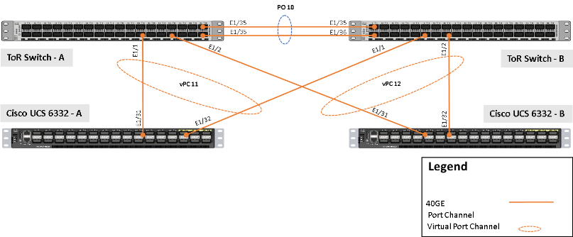
ToR Switch A
interface mgmt0
vrf member management
ip address 192.168.11.21/25
vpc domain 100
peer-switch
role priority 10
peer-keepalive destination 192.168.11.22 source 192.168.11.21
delay restore 150
peer-gateway
auto-recovery
interface port-channel10
description vPC Peer-Link
switchport mode trunk
switchport trunk allowed vlan 100, 125
spanning-tree port type network
mtu 9216
vpc peer-link
interface port-channel11
description vPC Connection to UCS-FI-6332-A
switchport mode trunk
switchport trunk allowed vlan 100, 125
spanning-tree port type edge trunk
mtu 9216
vpc 11
interface port-channel12
description Connection to UCS-FI-6332-B
switchport mode trunk
switchport trunk allowed vlan 100, 125
spanning-tree port type edge trunk
mtu 9216
vpc 12
interface Ethernet1/1
description Connection to UCS-FI-6332-A-1/31
switchport mode trunk
switchport trunk allowed vlan 100, 125
mtu 9216
channel-group 11 mode active
no shutdown
interface Ethernet1/2
description Connection to UCS-FI-6332-B-1/31
switchport mode trunk
switchport trunk allowed vlan 100, 125
mtu 9216
channel-group 12 mode active
no shutdown
ToR Switch B
interface mgmt0
vrf member management
ip address 192.168.11.22/25
vpc domain 100
peer-switch
role priority 20
peer-keepalive destination 192.168.11.21 source 192.168.11.22
delay restore 150
peer-gateway
auto-recovery
interface port-channel10
description vPC Peer-Link
switchport mode trunk
switchport trunk allowed vlan 100, 125
spanning-tree port type network
mtu 9216
vpc peer-link
interface port-channel11
description Connection to UCS-FI-6332-A
switchport mode trunk
switchport trunk allowed vlan 100, 125
spanning-tree port type edge trunk
mtu 9216
vpc 11
interface port-channel12
description Connection to UCS-FI-6332-B
switchport mode trunk
switchport trunk allowed vlan 100, 125
spanning-tree port type edge trunk
mtu 9216
vpc 12
interface Ethernet1/1
description Connection to UCS-FI-6332-A-1/32
switchport mode trunk
switchport trunk allowed vlan 100, 125
mtu 9216
channel-group 11 mode active
no shutdown
interface Ethernet1/2
description Connection to UCS-FI-6332-B-1/32
switchport mode trunk
switchport trunk allowed vlan 100, 125
mtu 9216
channel-group 12 mode active
no shutdown
HSRP with DHCP Relay Configuration Example
The following example shows the configuration of an SVI (Switch Virtual Interface) with HSRP (Hot Standby Routing Protocol). The IP DHCP relay statements point forward DHCP requests to the IP addresses of the DHCP servers that are on a different IP subnet.
ToR Switch A
interface Vlan100
description Azure-Stack-HCI-Tenant
no shutdown
mtu 9216
no ip redirects
ip address 192.168.100.2/24
ip directed-broadcast
no ipv6 redirects
hsrp version 2
hsrp 100
priority 150 forwarding-threshold lower 1 upper 150
ip 192.168.100.1
interface Vlan125
description Azure-Stack-HCI-Management
no shutdown
mtu 9216
no ip redirects
ip address 192.168.125.2/24
ip directed-broadcast
no ipv6 redirects
hsrp version 2
hsrp 125
priority 150 forwarding-threshold lower 1 upper 150
ip 192.168.125.1
ip dhcp relay address 192.168.51.15
ip dhcp relay address 192.168.53.15
ToR Switch B
interface Vlan100
description Azure-Stack-HCI-Tenant
no shutdown
mtu 9216
no ip redirects
ip address 192.168.100.3/24
ip directed-broadcast
no ipv6 redirects
hsrp version 2
hsrp 100
priority 140 forwarding-threshold lower 1 upper 140
ip 192.168.100.1
interface Vlan125
description Azure-Stack-HCI-Management
no shutdown
mtu 9216
no ip redirects
ip address 192.168.125.3/24
ip directed-broadcast
no ipv6 redirects
hsrp version 2
hsrp 125
priority 140 forwarding-threshold lower 1 upper 140
ip 192.168.125.1
ip dhcp relay address 192.168.51.15
ip dhcp relay address 192.168.53.15
Manual Cisco USC Manager Configuration
Procedure 1. Chassis Discovery Policy
Note: This procedure provides the details for modifying the chassis discovery policy as the base architecture includes two uplinks from each fabric extender installed in the Cisco UCS chassis.
Step 1. Navigate to the Equipment tab in the left pane and select the Equipment top-node object.
Step 2. In the right pane, click the Policies tab.
Step 3. Under Global Policies, change the Chassis Discovery Policy to 4-link or set it to match the number of uplink ports that are cabled between the chassis or fabric extenders (FEXs) and the fabric interconnects.
Step 4. Set Link Grouping Preference set to Port Channel.
Step 5. Select 40G for Backplane Speed Preference
Step 6. Keep Rack Server Discovery Policy Action at Immediate.
Step 7. Set Rack Management Connection Policy Action to Auto Acknowledged.
Step 8. Select Manual Blade Level Cap for the Global Power Allocation Policy
Step 9. Select User Acknowledge for the Firmware Auto Sync Server Policy
Step 10. Click Save Changes in the bottom right corner.
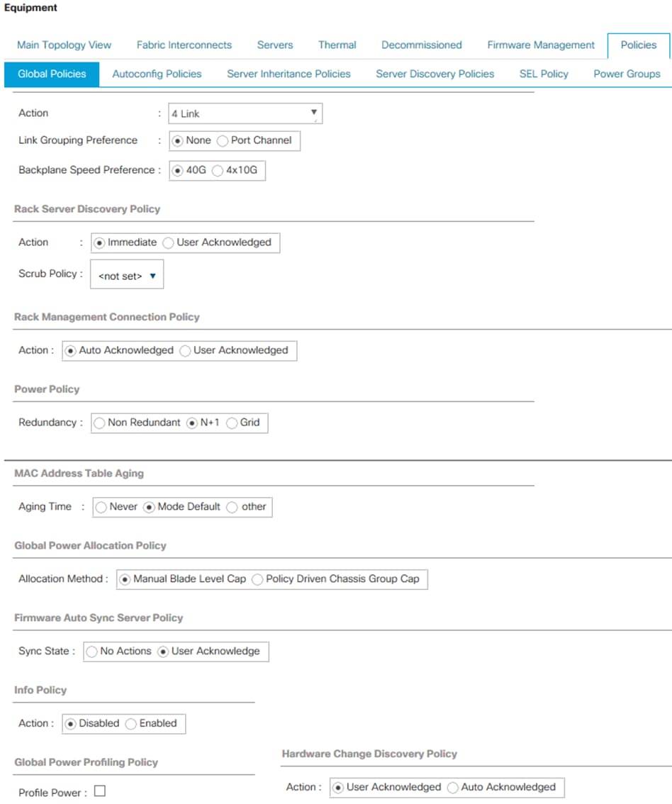
Configure Fabric Interconnect Ports
Procedure 1. Configure Uplink Ports
Step 1. Select the Equipment icon at the left of the window.
Step 2. Select Equipment > Fabric Interconnects > Fabric Interconnect A > Fixed Module.
Step 3. Expand the Ethernet Ports object.
Step 4. Select ports 31 and 32 that connect the upstream switches.
Step 5. Right-click them and select Configure as Uplink Port.
Step 6. A prompt displays asking if this is what you want to do. Click Yes, then click OK to continue.
Step 7. Repeat this procedure on Fabric Interconnect B.
Procedure 2. Configure Server Ports
Note: This procedure provides the details for enabling server, uplinks, and uplink ports.
Step 1. Select the Equipment icon at the left of the window.
Step 2. Select Equipment > Fabric Interconnects > Fabric Interconnect A > Fixed Module.
Step 3. Expand the Ethernet Ports object.
Step 4. Select the ports that are connected to servers and select Configure as Server Port.
Step 5. Click Yes to confirm the server ports, and then click OK.
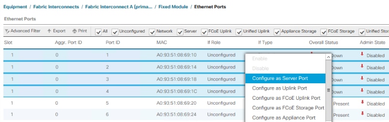
Step 6. Repeat this procedure on Fabric Interconnect B.
Procedure 3. Enable Priority Flow Control (PFC) on Server Ports
Note: Power Tools Must be used to enable PFC on the server port that connect Azure Stack hosts.
###########################################User ######################################################################
#UCSM Manager IP Address (Exmaple: "192.168.11.10")
$ucsmip = "192.168.11.10"
#UCSM Manager Login Credentials
$UCSCred = Get-Credential -Message "UCS Manager Credentials"
#List Fabric Inter Connect Port numbers connected to servers as described in the cabling diagram.
$serverports = @(1,2,3,4)
#Priority Flow Control Policy
$flowControlPolicy = @{FlowCtrlPolicy="AzureStack"}
#Path to UCS Power Tools. (Exmaple: "C:\Downloads\Cisco\PowerTools"
$ucspowertoolmodulepath = "C:\Downloads\Cisco\PowerTool"
############################################################################################################################
#Inatall PowerTool Modules from manually downloaded packages
Write-host "Importing Cisco UCS PowerTool modules from $ucspowertoolmodulepath"
Import-Module $ucspowertoolmodulepath\Cisco.Ucs.Core\Cisco.Ucs.Core.psd1 -ErrorVariable errVar
Import-Module $ucspowertoolmodulepath\Cisco.UcsManager\Cisco.UcsManager.psd1 -ErrorVariable errVar
#Inatall PowerTool from Online PSGallarey. May require PowerShellGet update.
Install-Module -Name Cisco.UCSManager – MinimumVersion 2.4.1.3 -Repository PSGallery -AcceptLicense -Force -SkipPublisherCheck -AllowClobber
Import-Module -Name Cisco.UCSManager
Get-Module -Name Cisco* | ft Name, Version
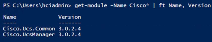
#Run the following PowerShell script to configure the Priority Flow Control Policy
try
{
$ucsmConn = Connect-Ucs -Name $ucsmip -Credential $UCSCred
Write-host "Successful login to UCS domain $ucsmip"
}
catch
{
Write-Host "Unsuccessful login to UCS domain $ucsmip"
$errTag = $True
}
try
{
Start-UcsTransaction -Ucs $ucsmConn
foreach ($serverport in $serverports)
{
Add-UcsServerPort -FabricServerCloud A -SlotId 1 -PortId $serverport -UsrLbl "Azure Stack HCI Server Port" -AdminState enabled -XtraProperty $flowControlPolicy -ModifyPresent
Add-UcsServerPort -FabricServerCloud B -SlotId 1 -PortId $serverport -UsrLbl "Azure Stack HCI Server Port" -AdminState enabled -XtraProperty $flowControlPolicy -ModifyPresent
}
Complete-UcsTransaction -ErrorAction Stop | Out-Null
}
catch
{
Write-Host "Failed to configure Server Port" "Error"
}
Write-Host "Disconnecting UCSM Manager at IP address $UCSMIPAddress"
Disconnect-Ucs -Ucs $ucsmConn -ErrorAction SilentlyContinue
Procedure 4. Configure Breakout Port for FEX Connectivity
Note: The following procedure is for use with the FEX model 2232TM-E. Please see the procedure in the main body of this document if your FEX model is 2348UPQ.
Note: Port 22 on each fabric interconnect has a QSFP-4SFP10G-CU1M breakout cable that connects the FEX (Fabric Extender). This port needs to be configured for breakout mode in order to accommodate this breakout cable. Each Fabric Interconnect will reboot as part of this breakout port configuration process.
Step 1. Click the Equipment icon.
Step 2. Select Equipment > Fabric Interconnects > Fabric Interconnect A > Fixed Module.
Step 3. Expand the Ethernet Ports object.
Step 4. Select port 22.
Step 5. Click Configure Breakout Port.
Step 6. Click Yes to confirm Breakout Port configuration and FI reboot.
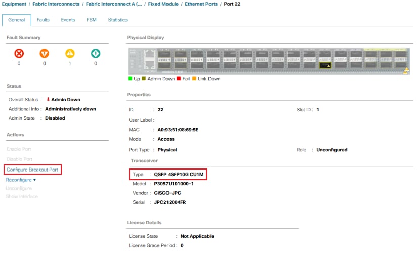
Step 7. Repeat this procedure on Fabric Interconnect B, Port 22.
Note: Fabric Interconnects will reboot after Breakout Port configuration.
Step 8. Login to Cisco UCS Manager after the reboot.
Step 9. Select Equipment > Fabric Interconnects > Fabric Interconnect A > Fixed Module.
Step 10. Expand the Ethernet Ports object.
Step 11. Port 22 will now be listed as Scalability Port 22.
Step 12. Select Scalability Port 22 in the left window pane.
Step 13. Select all 4 ports in the right windows pane, right-click and select Configure as Server Port.
Step 14. Click Yes to confirm configuration change.
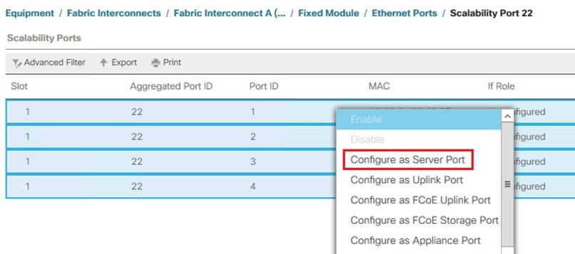
Step 15. Repeat this procedure on fabric interconnect B, port 22.
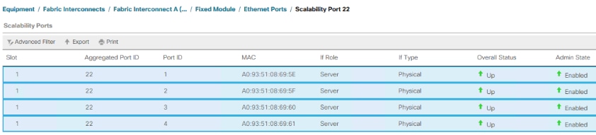
The FEX will be discovered automatically after the connecting ports is configured as server ports.
Note: Server discovery will begin once the FEXs are discovered. Server discovery will take approximately 20 minutes for discovery to complete. The initial status will be Inoperable, but it will soon change to Discovery.
Note: The administrator can proceed with the following configuration steps while server discovery is running I the background. Server discovery must complete before service profiles can be associated with the servers.
Network Configuration
Procedure 1. Create Sub-Organization
Step 1. Log back into Cisco USC Manager.
Step 2. Select the LAN icon at the left column of the window.
Step 3. Select Policies > Root.
Step 4. Right-click Organization and select Create Organization.
Step 5. Enter the name of the Organization that will be used for the Azure Stack deployment and an optional description.
Step 6. Click OK to create the organization.
Procedure 2. Add a Block of IP Addresses for KVM Access
This procedure provides the details for creating a block of KVM IP addresses for server access in the Cisco UCS environment.
Step 1. Log back into Cisco USC Manager.
Step 2. Select the LAN icon at the left column of the window.
Step 3. Select Pools > IP Pools.
Step 4. Right-click IP Pool ext-mgmt.
Step 5. Select Create Block of IPv4 Addresses.
Step 6. Enter the starting IP address of the block and number of IP addresses needed as well as the subnet mask and gateway information.
Note: The IP address range needs to be on the same subnet as the UCSM Manager Out-of-Band management address.
Step 7. Click OK to create the IP block.
Step 8. Click OK in the message box.
Procedure 3. Create Uplink Port Channels to Upstream Switches
This procedure provides the details for configuring the necessary Port Channels out of the Cisco UCS environment.
Note: Two Port Channels are created, one from fabric A to both upstream switches and one from fabric B to both upstream switches.
Step 1. Select the LAN icon on the left of the window.
Step 2. Under LAN Cloud, expand the Fabric A tree.
Step 3. Right-click Port Channels.
Step 4. Select Create Port Channel.
Step 5. Enter 11 as the unique ID of the Port Channel.
Step 6. Enter VPC11 as the name of the Port Channel.
Step 7. Click Next.
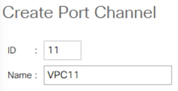
Step 8. Select the port with slot ID: 1 and port: 31 and also the port with slot ID: 1 and port 32 to be added to the Port Channel.
Step 9. Click >> to add the ports to the Port Channel.

Step 10. Click Finish to create the Port Channel.
Step 11. Expand the Port Channel node and click on the newly created port channel to view the status.
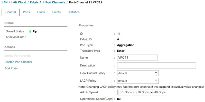
Note: The port channel formation may take up to 60 seconds.
Step 12. Under LAN Cloud, expand the Fabric B tree.
Step 13. Right-click Port Channels.
Step 14. Select Create Port Channel.
Step 15. Enter 12 as the unique ID of the Port Channel.
Step 16. Enter VPC12 as the name of the Port Channel.
Step 17. Click Next.
Step 18. Select the port with slot ID: 1 and port: 31 and also the port with slot ID: 1 and port 32 to be added to the Port Channel.
Step 19. Click >> to add the ports to the Port Channel.
Step 20. Click Finish to create the Port Channel.
Step 21. Expand the Port Channel node and click on the newly created port channel to view the status.

Note: The port channel formation may take up to 60 seconds.
Procedure 4. Create VLANs
The following VLANs need to be created. Additional VLANs can be created as necessary for virtual machine networks.
| VLAN Name |
VLAN ID |
| Management |
125 |
| Tenant |
100 |
| Storage-A |
107 |
| Storage-B |
207 |
Note: This procedure provides the details for configuring the necessary VLANs for the Cisco UCS environment.
Step 1. Select the LAN icon in the left column.
Note: Three VLANs are created.
Step 2. Select LAN Cloud.
Step 3. Right-click VLANs.
Step 4. Select Create VLANs.
Step 5. Enter Infrastructure as the name of the VLAN to be used for management traffic.
Step 6. Keep the Common/Global option selected for the scope of the VLAN.
Step 7. Enter the VLAN ID for the management VLAN. Keep the sharing type as None.
Step 8. Click OK.
Step 9. Repeat steps 3 through 8 to create all VLANs.
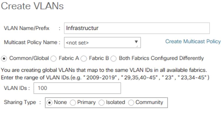
Step 10. Right-click VLANs.
Step 11. Select Create VLANs.
Step 12. Enter Storage-A as the name of the VLAN to be used for management traffic.
Step 13. Keep the Common/Global option selected for the scope of the VLAN.
Step 14. Enter the VLAN ID for the Storage-A VLAN. Keep the sharing type as None.
Step 15. Click OK.
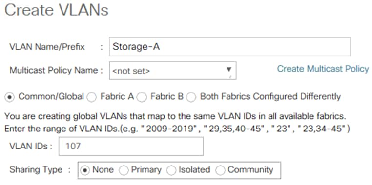
Step 16. Right-click VLANs.
Step 17. Select Create VLANs.
Step 18. Enter Storage-B as the name of the VLAN to be used for management traffic.
Step 19. Keep the Common/Global option selected for the scope of the VLAN.
Step 20. Enter the VLAN ID for the Storage-B VLAN. Keep the sharing type as None.
Step 21. Click OK.
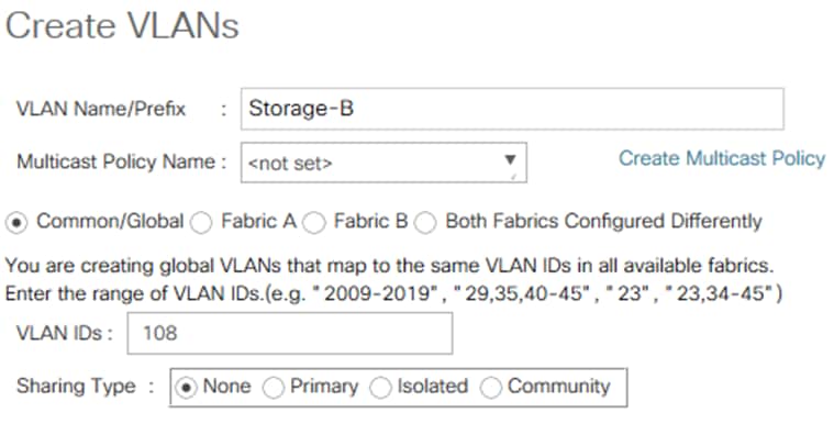
Step 22. Repeat this procedure to create all VLANs.
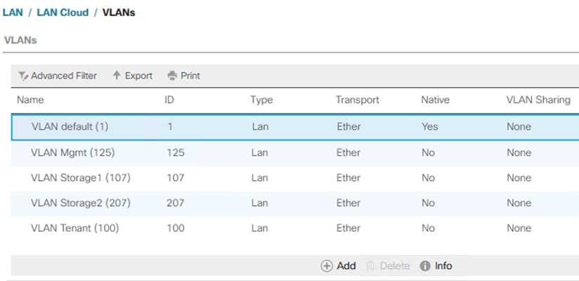
Procedure 5. Create a MAC Address Pool
This procedure provides the details for configuring the necessary MAC address pool for the Cisco UCS environment. Two MAC address Pools will be created. One pool for Fabric A and another pool for Fabric B.
Step 1. Select the LAN icon in the left column.
Step 2. Select Pools > root> MAC Pools > Sub-Organizations > AzS-HCI > MAC Pools MAC.
Step 3. Right-click MAC Pools and select Create MAC Pool.
Step 4. Enter Pool Name : Ethernet-A
Step 5. Select Sequential Assignment Order.
Step 6. Click Next.
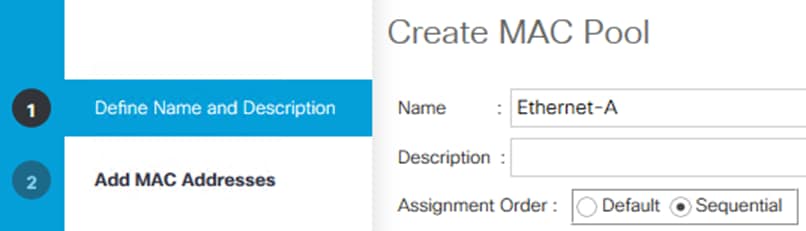
Step 7. Click Add.
Step 8. Specify a starting MAC address.
Step 9. Specify a size of the MAC address pool sufficient to support the available blade resources.
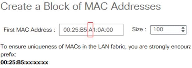
Step 10. Right-click MAC Pools and select Create MAC Pool.
Step 11. Enter Pool Name : Ethernet-B
Step 12. Select Sequential Assignment Order.
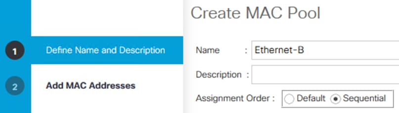
Step 13. Click Next.
Step 14. Click Add.
Step 15. Specify a starting MAC address.
Step 16. Specify a size of the MAC address pool sufficient to support the available blade resources.
Step 17. Click OK.
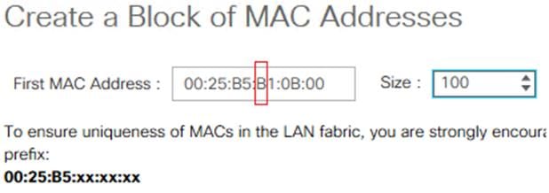
Step 18. Click Finish.
Procedure 6. Set Enable Quality of Service and Jumbo Frames in Cisco UCS Fabric
This procedure provides the details for setting Jumbo frames and enabling the quality of service in the Cisco UCS Fabric.
Step 1. Select the LAN icon in the left column.
Step 2. Go to LAN Cloud > QOS System Class.
Step 3. In the right pane, click the General tab.
Step 4. On the Platinum, Bronze and Best Effort row, select enable check box and type 9216 in the MTU boxes.
Step 5. Clear the Packet Drop check box for the Platinum priority.
Step 6. Check the Enabled checkbox for Platinum and Bronze priorities.
Step 7. Set Weight to 10 for the Platinum and Best Effort priorities.
Step 8. Set Platinum priority to CoS 1 and Bonze priority to Cos 5.
Step 9. Change the Weight values to the following settings:
| Priority |
Weight |
| Platinum |
10 |
| Bronze |
1 |
| Best Effort |
9 |
| Fibre Channel |
none |
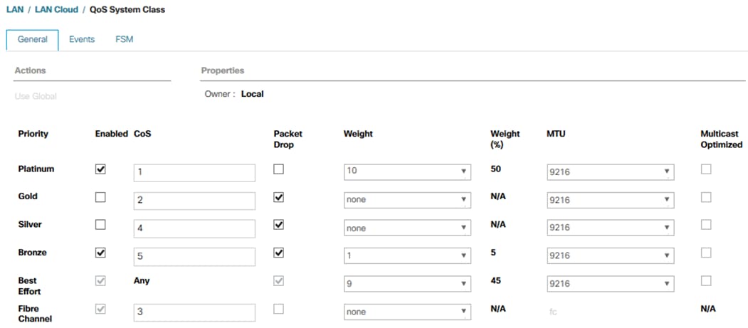
Note: If FCOE is in use, do not set Fibre Channel Weight to None.
Step 10. Click Save Changes in the bottom right corner.
Step 11. Click Yes to QoS Change Warning message.
Step 12. Select the LAN tab on the left of the window.
Procedure 7. Create Flow Control Policy
This procedure creates the Priority Flow Control (PFC) on the Fabric Interconnects.
Step 1. In Cisco UCS Manager, click the LAN icon in the left column.
Step 2. Select Policies > root.
Step 3. Expand the suborganizations and select the previously created suborganization
Step 4. Select Flow Control Policies in the left pane and click add right pane.
Step 5. Enter AzureStack as the policy name.
Step 6. Set Priority to On.
Step 7. Click OK to create the network control policy.
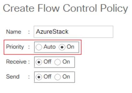
Procedure 8. Create Network Control Policy for Cisco Discovery Protocol
This procedures creates a network control policy that enables Cisco Discovery Protocol (CDP) on virtual network ports.
Step 1. In Cisco UCS Manager, click the LAN icon in the left column.
Step 2. Select Policies > root.
Step 3. Expand the suborganizations and select the previously created suborganization.
Step 4. Select Network Control Policies tab in the right pane.
Step 5. Right click on the previously created suborganization and select Create Network Control Policy.
Step 6. Enter Enable_CDP as the policy name.
Step 7. For CDP, select the Enabled option.
Step 8. Click OK to create the network control policy.
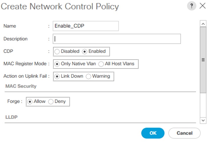
Procedure 9. Create a vNIC Template
Step 1. Select the LAN icon in the left column.
Step 2. Go to Policies > root > and the previously created sub organization.
Note: The vNIC template needs to be created in the same organization where the MAC Address Pools were created.
Step 3. Right-click vNIC Templates.
Step 4. Select Create vNIC Template.
Step 5. Enter Ethernet-A as the vNIC template name.
Step 6. Configure options:
a. Leave Fabric A checked.
b. Under target, unselect the VM check box.
c. Select Updating Template as the Template Type.
d. Under VLANs, select Infrastructure and Storage-A VLANs
e. Set Infrastructure as the Native VLAN.
Note: The native VLAN allows communication without specifying the VLAN tag. The native VLAN is required in the host partition for PXE booting and must be assigned to the VLAN that is used for PXE booting.
f. Leave MTU set to 9000.
g. For MAC Pool, select the MAC pool Ethernet-A created earlier.
Step 7. Click OK to complete creating the vNIC template.
Step 8. Click OK.
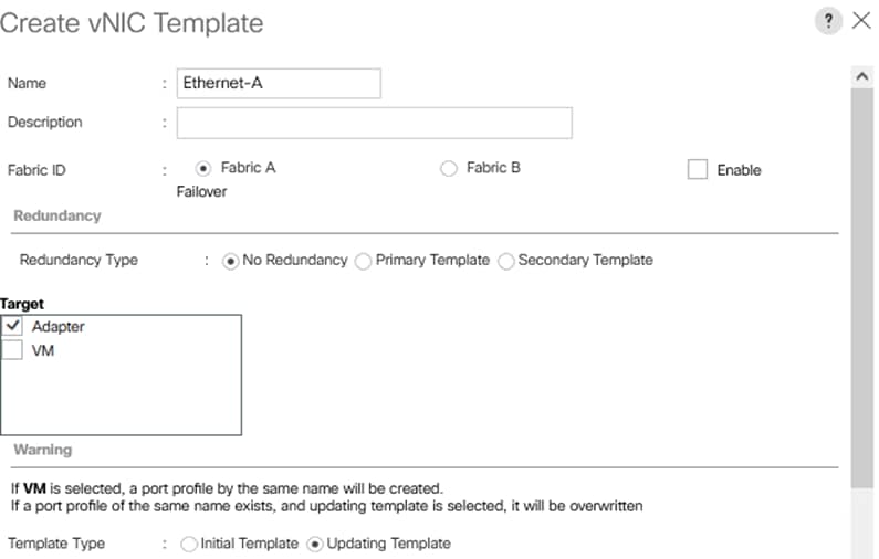
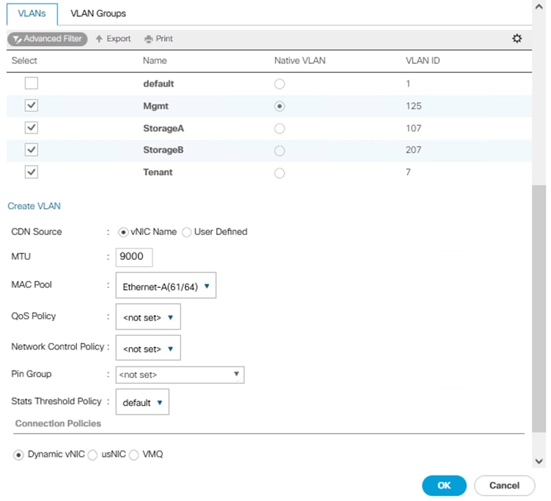
Step 9. Repeat this procedure to create vNICs Ethernet-B with the following parameters:
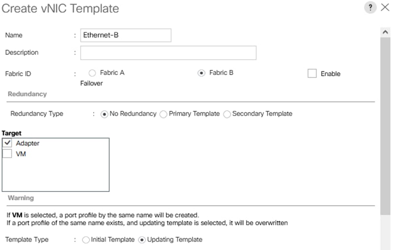
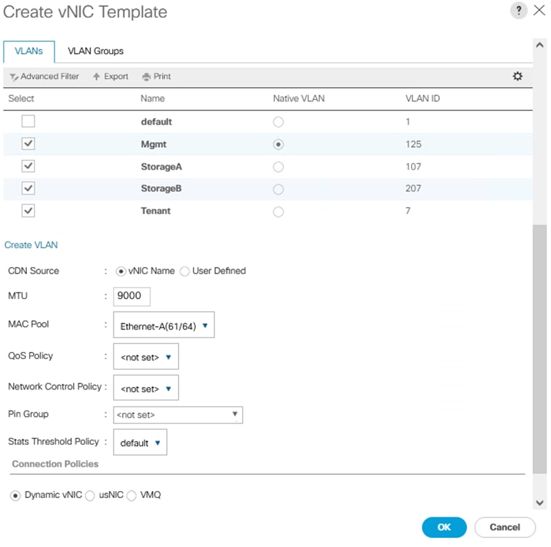
Procedure 1. Create a Storage Profile
Step 1. Select the Storage icon in the left column of the window.
Step 2. Go to Storage Profiles > root >and the previously created sub organization.
Step 3. Right-click the previously created sub organization and select Create Storage Profile.
Step 4. Enter the name RAID1-Boot and optionally provide the description.
Step 5. Select the Controller Definitions tab and click Add.
Step 6. Enter the name RAID1-Mirrored.
Step 7. Leave Protect Configuration checked.
Step 8. In the RAID Level drop-down list Select RAID 1 Mirrored.
Step 9. Click OK.
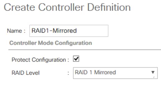
Step 10. Click OK to create the Storage Profile.
Procedure 1. Create UUID Suffix Pools
Note: This procedure provides the details for configuring the necessary UUID suffix pools for the Cisco UCS environment. The UUID suffix value can be created by using a GUID generation tool. This method produces a UUID value with the highest uniqueness probability. Windows includes the New-GUID PowerShell cmdlet that dynamically generates a GUID.
Step 1. Run PowerShell command in a PowerShell window to get a GUID suffix:
((new-guid) -split "-",4)[3]
Step 2. Copy the 16 digits of the GUID suffix and use it for the UCS UUID Suffix
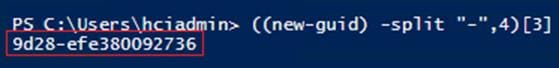
Step 3. In Cisco UCS Manager select the Servers icon.
Step 4. Select Pools > root.
Step 5. Expand UUID Suffix Pools.
Step 6. Right-click Pool default and select Create a Block of UUID Suffixes.
Step 7. Enter the last 16 digits of the GUID that was previously generated by the New-GUID cmdlet.
Step 8. Specify a size of the UUID block sufficient to support the available server resources.
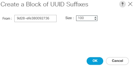
Procedure 2. Create a Server Pool
Step 1. Select the Servers icon in the left column.
Step 2. Go to Pools> root or sub-organization
Step 3. Right-click Server Pools and select Create Server Pool.
Step 4. Name the pool AzureStack-HCI and optionally add a description.
Step 5. Click Next.
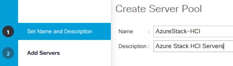
Step 6. Select the Azure Stack HCI servers in the Servers table on the left.
Step 7. Click >> to add the servers to the Pools Servers in the table on the right.
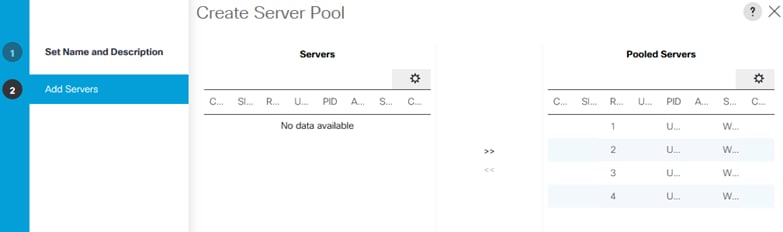
Step 8. Click Finish to create the Server Pool.
Procedure 3. Create a Server BIOS Policy
Step 1. Select the Servers icon in the left column.
Step 2. Go to Policies > root > and the previously created sub organization.
Step 3. Right-click BIOS Policies.
Step 4. Select Create BIOS Policy.
Step 5. Enter AzS-HCI-C240M5 as the BIOS policy name.
Step 6. Enter the Description.
Step 7. Do not check Reboot on BIOS Settings Change.
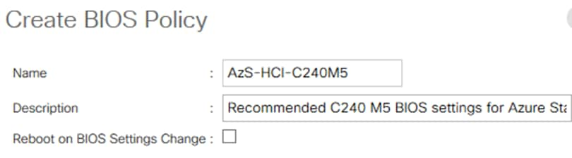
Step 8. Click on the newly created BIOS policy.
Step 9. Configure the following BIOS settings. If the property is not listed in the following table, it does not apply to the Cisco UCS C240M5 server and should be set to the value Platform Default.
| Section |
Property |
Platform Default |
Required Value |
| Main |
PCIe Slots CDN Control |
Disabled |
Enabled |
|
|
CDN Control |
Disabled |
Enabled |
|
|
Front Panel Lockout |
|
Disabled |
|
|
Post Error Pause |
|
Disabled |
|
|
Quiet Boot |
|
Disabled |
|
|
Resume on AC Power Loss |
|
Platform Default |
|
|
|
|
|
| Advanced - Processor |
Altitude |
|
Platform Default |
|
|
CPU Hardware Power Management |
HWPM Native Mode |
Platform Default |
|
|
Boot Performance Mode |
Max Performance |
Platform Default |
|
|
CPU Performance |
Custom |
Enterprise |
|
|
Configurable TDP Level |
|
Platform Default |
|
|
Core Multi Processing |
All |
Platform Default |
|
|
DCPMM Firmware Downgrade |
0 |
Platform Default |
| VMD |
DRAM Clock Throttling |
|
Platform Default |
|
|
Direct Cache Access |
|
Enabled |
|
|
Energy Performance Tuning |
OS |
Platform Default |
|
|
Enhanced Intel Speed Step Tech |
1 |
Disabled |
|
|
Execute Disable Bit |
1 |
Platform Default |
|
|
Frequency Floor Override |
|
Platform Default |
|
|
Intel Hyper Threading Tech |
1 |
Enabled |
|
|
Energy Efficient Turbo |
0 |
Platform Default |
|
|
Inter Turbo Boost Tech |
1 |
Enabled |
|
|
Inter Virtualization Technology |
1 |
Enabled |
|
|
Intel Speed Select |
Base |
Platform Default |
|
|
Channel Interleaving |
|
Platform Default |
|
|
IMC Interleaving |
Auto |
Platform Default |
|
|
Memory Interleaving |
|
Platform Default |
|
|
Rank Interleaving |
|
Platform Default |
|
|
Sub NUMA Clustering |
0 |
Disabled |
|
|
Local X2 Apic |
0 |
X2APIC |
|
|
Max Variable MTTR Setting |
|
Platform Default |
|
|
P STATE Coordination |
|
Platform Default |
|
|
Package C State Limit |
C0, C1 State |
Platform Default |
|
|
Autonomous Core C-state |
0 |
Platform Default |
|
|
Processor C State |
|
Disabled |
|
|
Processor C1E |
0 |
Disabled |
|
|
Processor C3 Report |
|
Enabled |
|
|
Processor C6 Report |
0 |
Disabled |
|
|
Processor C7 Report |
|
Enabled |
|
|
Processor CMCI |
1 |
Platform Default |
|
|
Power Technology |
|
Performance |
|
|
Energy Performance |
Balanced |
Platform Default |
|
|
ProcessorEppProfile |
Balanced |
Platform Default |
|
|
Adjacent Cache Line Prefetcher |
1 |
Platform Default |
|
|
DCU IP Prefetcher |
1 |
Enabled |
|
|
DCU Streamer Prefetch |
1 |
Enabled |
|
|
Hardware Prefetcher |
1 |
Enabled |
|
|
UPI Prefetch |
|
Enabled |
|
|
LLC Prefetch |
0 |
Disabled |
|
|
XPT Prefetch |
0 |
Enabled |
|
|
Core Performance Boost |
|
Platform Default |
|
|
Downcore Control |
|
Platform Default |
|
|
Global C-state Control |
|
Platform Default |
|
|
L1 Steam HW Prefetch |
|
Platform Default |
|
|
L2 Steam HW Prefetch |
|
Platform Default |
|
|
Determinism Slider |
|
Platform Default |
|
|
IOMMU |
|
Platform Default |
|
|
Bank Group Swap |
|
Platform Default |
|
|
Chipset Interleaving |
|
Platform Default |
|
|
Configurable TDP Control |
|
Platform Default |
|
|
AMD Memory Interleaving |
|
Platform Default |
|
|
AMD Memory Interleaving Size |
|
Platform Default |
|
|
SMEE |
|
Platform Default |
|
|
SMT Mode |
|
Platform Default |
|
|
SVM Mode |
|
Platform Default |
|
|
Demand Scrub |
|
Platform Default |
|
|
Patrol Scrub |
1 |
Enabled |
|
|
Workload Configuration |
|
Platform Default |
|
|
|
|
|
| Advanced - Intel Directed IO |
Intel VTD ATS support |
1 |
Platform Default |
|
|
Intel VTD coherency support |
0 |
Platform Default |
|
|
Intel VT for directed IO |
1 |
Enabled |
|
|
Intel VTD interrupt Remapping |
|
Platform Default |
|
|
Intel VTD pass through DMA support |
|
Platform Default |
|
|
|
|
|
| Advanced - RAS Memory |
DDR3 Voltage Selection |
|
Platform Default |
|
|
DRAM Refresh Rate |
|
Platform Default |
|
|
LV DDR Mode |
|
Platform Default |
|
|
Mirroring Mode |
|
Platform Default |
|
|
NUMA optimized |
1 |
Enabled |
|
|
Select PPR type configuration |
|
Platform Default |
|
|
Memory Size Limit in GB |
|
Platform Default |
|
|
Partial Mirror percentage |
|
Platform Default |
|
|
Partial Mirror 1 Size in GB |
|
Platform Default |
|
|
Partial Mirror 2 Size in GB |
|
Platform Default |
|
|
Partial Mirror 3 Size in GB |
|
Platform Default |
|
|
Partial Mirror 4 Size in GB |
|
Platform Default |
|
|
Memory RAS configuration |
ADDDC Sparing |
Platform Default |
|
|
|
|
|
| Advanced - Serial Port |
Serial A enabled |
|
Platform Default |
|
|
|
|
|
| Advanced - USB |
All USB Devices |
|
Platform Default |
|
|
Make Device Non-Bootable |
|
Platform Default |
|
|
Legacy USB Support |
1 |
Platform Default |
|
|
xHCI Mode |
1 |
Platform Default |
|
|
USB Front Panel Access Lock |
|
Platform Default |
|
|
USB Idle Power Optimization |
|
Platform Default |
|
|
Port 60/64 Emulation |
1 |
Platform Default |
|
|
USB Port Front |
1 |
Platform Default |
|
|
USB Port Internal |
1 |
Platform Default |
|
|
USB Port KVM |
1 |
Platform Default |
|
|
USB Port Rear |
1 |
Platform Default |
|
|
USB Port SD Card |
1 |
Platform Default |
|
|
USB Port VMedia |
1 |
Platform Default |
|
|
|
|
Platform Default |
|
|
|
|
|
| Advanced - PCI |
ASPM Support |
|
Platform Default |
|
|
BME DMA Mitigation |
0 |
Platform Default |
|
|
Maximum memory below 4GB |
|
Platform Default |
|
|
Memory mapped IO above 4GB |
1 |
Platform Default |
|
|
VGA Priority |
OnBoard |
Platform Default |
|
|
|
|
|
| Advanced - QPI |
QPI Link Frequency Select |
|
Platform Default |
|
|
QPI Snoop Mode |
|
Platform Default |
|
|
|
|
|
| Advanced - LOM and PCI Slots |
All Onboard LOM Ports |
1 |
Disabled |
|
|
CDN Support for LOMs |
|
Disabled |
|
|
VMD Enabled |
0 |
Platform Default |
|
|
LOM port 0 OptionsROM |
1 |
Platform Default |
|
|
LOM port 1 OptionsROM |
1 |
Platform Default |
|
|
PCIe Slot 1 OptionsROM |
1 |
Platform Default |
|
|
PCIe Slot 2 OptionsROM |
1 |
Platform Default |
|
|
PCIe Slot 3 OptionsROM |
|
Platform Default |
|
|
PCIe Slot 4 OptionsROM |
1 |
Platform Default |
|
|
PCIe Slot 5 OptionsROM |
1 |
Platform Default |
|
|
PCIe Slot 6 OptionsROM |
1 |
Platform Default |
|
|
PCIe Slot MLOM OptionROM |
1 |
Platform Default |
|
|
PCIe Slot MRAID OptionROM |
1 |
Platform Default |
|
|
PCIe Slot N1 OptionROM |
1 |
Platform Default |
|
|
PCIe Slot N2 OptionROM |
1 |
Platform Default |
|
|
PCIe Slot N3 OptionROM |
1 |
Platform Default |
|
|
PCIe Slot N4 OptionROM |
1 |
Platform Default |
|
|
PCIe Slot N5 OptionROM |
1 |
Platform Default |
|
|
PCIe Slot N6 OptionROM |
1 |
Platform Default |
|
|
PCIe Slot N7 OptionROM |
1 |
Platform Default |
|
|
PCIe Slot N8 OptionROM |
1 |
Platform Default |
|
|
PCIe Slot Rear NVMe1 OptionROM |
1 |
Platform Default |
|
|
PCIe Slot Rear NVMe2 OptionROM |
1 |
Platform Default |
|
|
MRAID Link Speed |
Auto |
Platform Default |
|
|
MLOM Link Speed |
Auto |
Platform Default |
|
|
PCIe Slot 1 Link Speed |
Auto |
Platform Default |
|
|
PCIe Slot 2 Link Speed |
Auto |
Platform Default |
|
|
PCIe Slot 3 Link Speed |
Auto |
Platform Default |
|
|
PCIe Slot 4 Link Speed |
Auto |
Platform Default |
|
|
PCIe Slot 5 Link Speed |
Auto |
Platform Default |
|
|
PCIe Slot 6 Link Speed |
Auto |
Platform Default |
|
|
Front NVME1 Link Speed |
Auto |
Platform Default |
|
|
Front NVME2 Link Speed |
Auto |
Platform Default |
|
|
Rear NVME1 Link Speed |
Auto |
Platform Default |
|
|
Rear NVME2 Link Speed |
Auto |
Platform Default |
|
|
|
|
|
| Advanced - Trusted Platform |
Trusted Platform Technology (TXT) |
0 |
Disabled |
|
|
SHA-1 PCR Bank |
|
Platform Default |
|
|
SHA-256 PCR Bank |
|
Platform Default |
|
|
Trusted Platform Module (TPM) |
1 |
Enabled |
|
|
|
|
|
| Advanced - Graphics Configuration |
Integrated Graphics Aperture Size |
|
Platform Default |
|
|
Integrated Graphics Control |
|
Platform Default |
|
|
Onboard Graphics |
|
Platform Default |
|
|
|
|
|
| Boot Options |
Adaptive Memory Training |
1 |
Platform Default |
|
|
BIOS Techlog Level |
Minimum |
Platform Default |
|
|
Cool Down Time (Sec) |
|
Platform Default |
|
|
Number of Retries |
|
Platform Default |
|
|
Boot options retry |
|
Platform Default |
|
|
SAS RAID module |
|
Platform Default |
|
|
SAS RAID |
|
Platform Default |
|
|
Onboard SCU Storage Support |
|
Platform Default |
|
|
Option ROM Launch Optimization |
|
Platform Default |
|
|
P-SATA mode |
LSI SWRAID |
LSI SWRAID |
|
|
IPv4 PXE Support |
|
Platform Default |
|
|
IPv6 PXE Support |
0 |
Platform Default |
|
|
Network Stack |
|
Platform Default |
|
|
|
|
|
| Server Management |
Assert NMI on PERR |
|
Platform Default |
|
|
Assert NMI on SERR |
|
Platform Default |
|
|
Baud rate |
115.2k |
Platform Default |
|
|
Console Redirection |
0 |
Platform Default |
|
|
Flow Control |
None |
Platform Default |
|
|
Legacy OS Redirection |
|
Platform Default |
|
|
Putty KeyPad |
|
Platform Default |
|
|
Terminal type |
VT100 |
Platform Default |
|
|
FRB-2 Timer |
1 |
Platform Default |
|
|
OS Boot Watchdog Timer Policy |
Power Off |
Platform Default |
|
|
OS Boot Watchdog Timer Timeout |
10 Minutes |
Platform Default |
|
|
OS Boot Watchdog Timer |
0 |
Platform Default |
|
|
Out of Band Management |
|
Platform Default |
|
|
Redirect After BIOS Post |
Disabled |
Platform Default |
Procedure 4. Create Boot Policies
Step 1. Select the Servers icon in the left column.
Step 2. Go to Policies > root > and the previously created sub organization.
Step 3. Right-click Boot Policies.
Step 4. Select Create Boot Policy.
Step 5. Name the boot policy EmbLUN-DVD-LAN.
Step 6. (Optional) Give the boot policy a description.
Step 7. Leave Reboot on Boot Order Change unchecked.
Step 8. Leave Enforce vNIC/HBA/iSCSI Name checked.
Step 9. Set Boot Mode to UEFI.
Step 10. Enable Secure Boot by checking the Boot Security checkbox.
Step 11. Expand the Local Devices drop-down menu and select Add Embedded Local LUN, and Local CD/DVD.
Step 12. Expand the vNICs dropdown and add LAN Boot
Step 13. Enter the vNIC name Ethernet-A and select IP Address Type Ipv4.
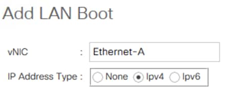
Step 14. Select Embedded LUN and click Set Uefi Boot Parameters.
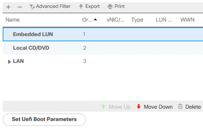
Step 15. Enter the following parameters:
● Boot Loader Name: bootmgfw.efi
● Boot Loader Path: \EFI\Microsoft\Boot
● Boot Loader Description: Windows Boot Manager
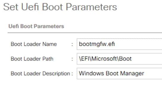
Note: LAN is used for PXE boot. Local CD/DVD is used for vMedia ISO boot. One of these options can be removed if not used.
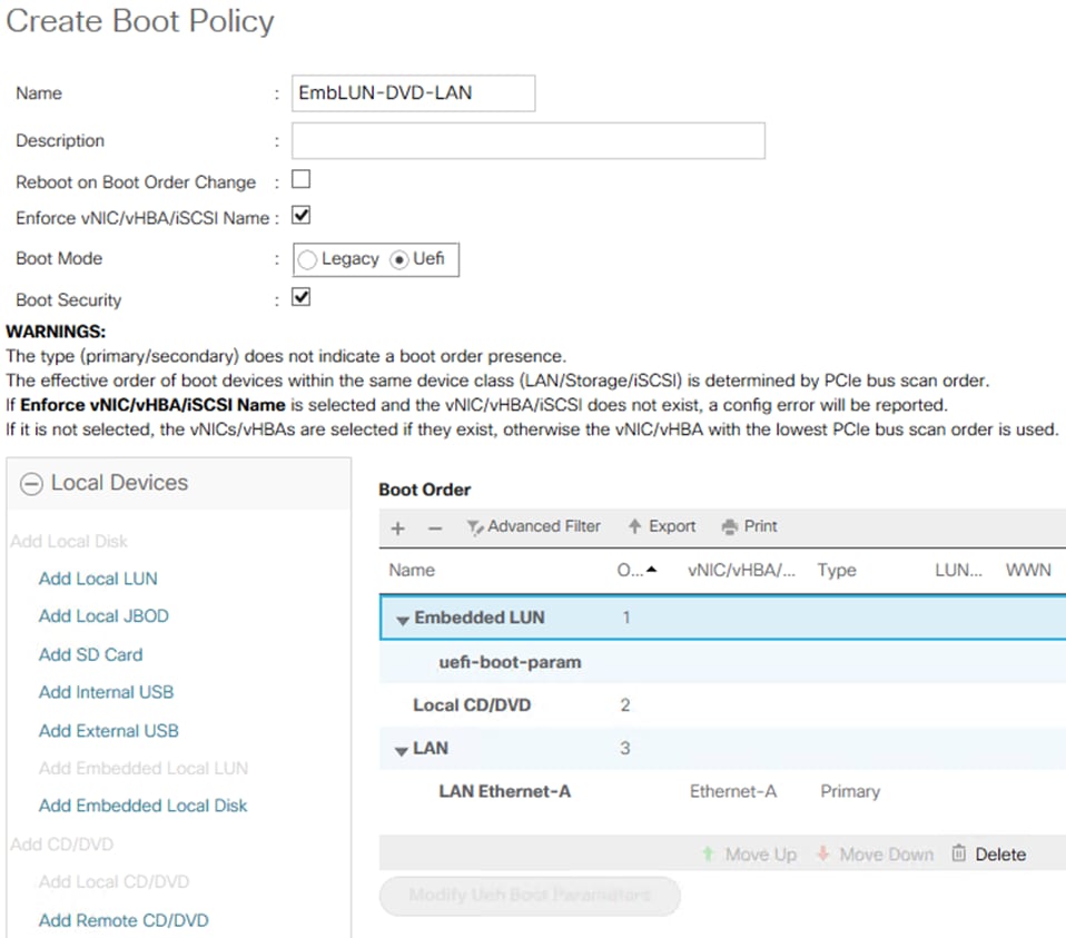
Procedure 5. Create Host Firmware Package Policy
Note: This procedure provides the details for creating a firmware management policy for a given server configuration in the Cisco UCS environment. Firmware management policies allow the administrator to select the corresponding packages for a given server configuration. These often include adapter, BIOS, board controller, FC adapters, HBA option ROM, and storage controller properties.
Step 1. Select the Servers icon in the left column.
Step 2. Select Policies > root or a suborganization.
Step 3. Right-click Host Firmware Packages.
Step 4. Select Create Host Firmware Package.
Step 5. Enter the name of the host firmware package for the corresponding server configuration and an optional description.
Step 6. Two types of host firmware package are available. The simple option specifies all firmware based on a firmware version bundle. The Advanced option allows granular control of the firmware version for each device type. Select the Simple option.
Step 7. Select the required Rack Package version from the drop-down list.
Step 8. Clear the check box next to Local Disk in the Excluded Components list box.
Step 9. Click OK to create the host firmware package.
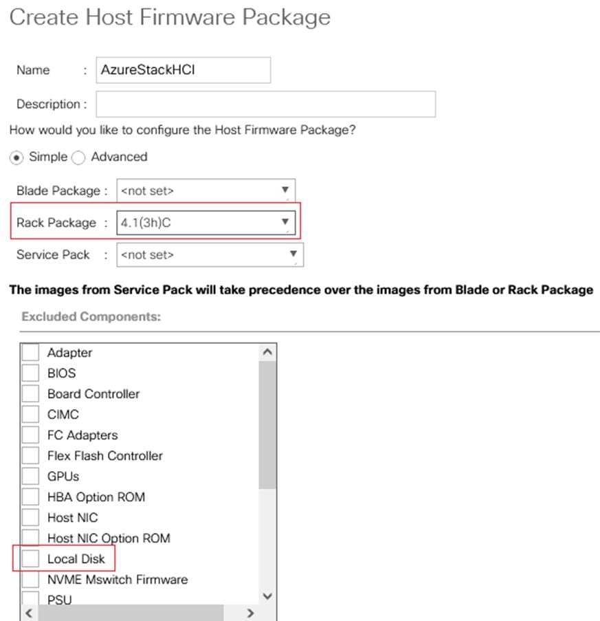
Procedure 6. Create a Local Disk Configuration Policy
Note: This procedure provides the details for creating a local disk configuration for the Cisco UCS environment, which is necessary if the servers in question do not have a local disk.
Note: This policy should not be used on blades that contain local disks.
Step 1. Select the Servers icon in the left column.
Step 2. Go to Policies > root > and the previously created sub organization.
Step 3. Right-click Local Disk Config Policies.
Step 4. Select Create Local Disk Configuration Policy.
Step 5. Enter AnyConfig as the local disk configuration policy name.
Step 6. Change the Mode to Any Configuration.
Step 7. Click OK to complete creating the Local Disk Configuration Policy.
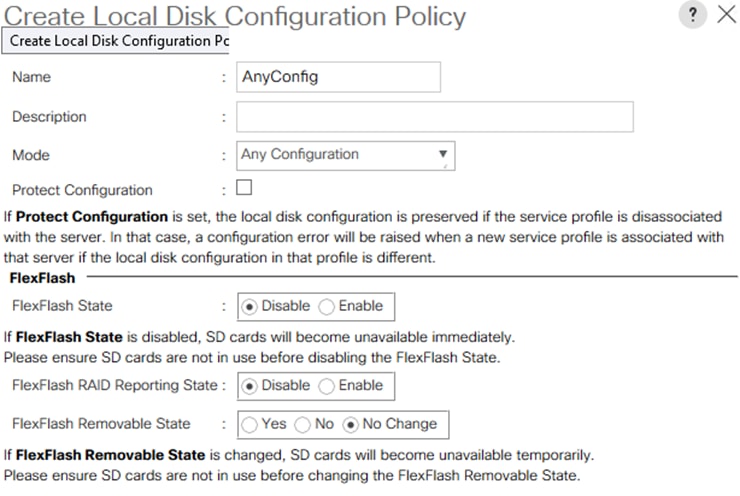
Procedure 7. Create a Maintenance Policy
Note: This procedure provides the details for creating a maintenance policy. The maintenance policy controls the timing of a server reboot after an update has been made that requires the server to reboot prior to the update taking affect.
Step 1. Select the Servers icon in the left column.
Step 2. Go to Policies > root or sub-organization.
Step 3. Right-click Maintenance Policy and select Create Maintenance Policy.
Step 4. Name the policy UserAck.
Step 5. Select the User Ack option.
Step 6. Select the option On Next Boot.
Step 7. Click OK to create the policy.
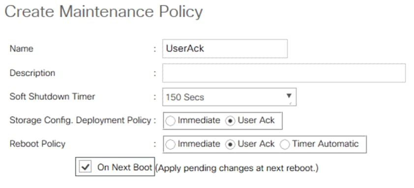
Procedure 8. Create a Power Control Policy
Step 1. Select the Servers icon in the left column.
Step 2. Go to Policies > root >and the previously created sub-organization.
Step 3. Right-click Power Controller Policies.
Step 4. Select Create Power Control Policy.
Step 5. Select Any Fan speed policy
Step 6. Enter NoCap as the power control policy name.
Step 7. Change the Power Capping to No Cap.
Step 8. Click OK to complete creating the host firmware package.
Step 9. Click OK.
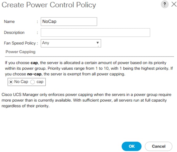
Procedure 9. Create a Scrub Policy
Step 1. Select the Servers icon in the left column.
Step 2. Go to Policies > root >and the previously created sub organization.
Step 3. Right-click Scrub Policies and select Create Scrub Policy.
Step 4. Enter the name NoScurb and an optional description.
Step 5. Set all scrub options to No.
Step 6. Click OK.
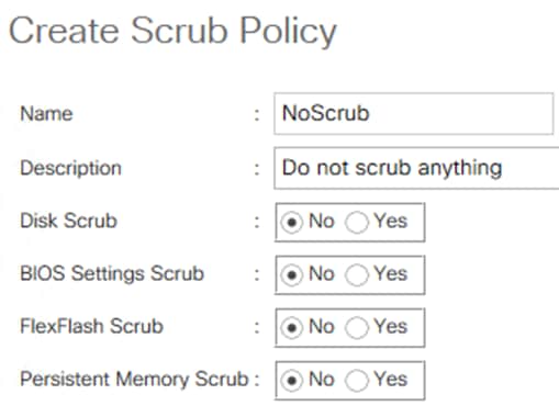
Procedure 10. Create a Server Pool Policy Qualification
Step 1. Select the Servers icon in the left column.
Step 2. Go to Policies > root.
IMPORTANT! This policy must be created under the Policy Root object. It cannot be created in a sub-organization.
Step 3. Right-click Server Pool Policy Qualification and select Create Server Pool Policy Qualification.
Step 4. Name the policy C240M5L or C240M5SX depending on your server model
Step 5. Select the action Create Server PID Qualifications.
Step 6. From the drop-down list select UCSC-C240-M5L or UCSC-C240-M5SX and click OK.
Step 7. Click OK to create the Server Pool Policy Qualification.
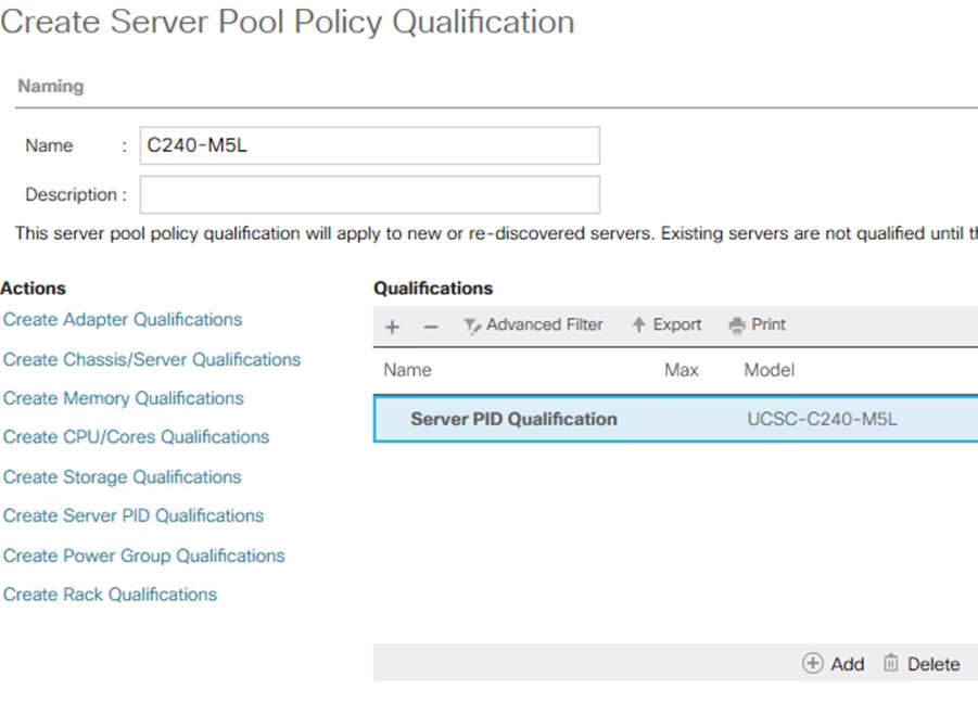
Procedure 11. Create a Server Pool Policy
Step 1. Select the Servers icon in the left column.
Step 2. Go to Policies > root or sub-organization
Step 3. Right-click Server Pool Policies and select Create Server Pool Policy.
Step 4. Name the policy AzS-HCI-C240M5L or C240M5SX depending on your server model and optionally add a description.
Step 5. In the Target Pool dropdown box select the previously created Server Pool AzureStack-HCI.
Step 6. In the Qualification dropdown box select the previously created qualification policy C240-M5L or C240M5SX depending on your server model.
Step 7. Click OK to create the Server Pool policy.
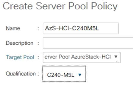
Create Service Profile Templates
Procedure 1. Service Profile Template Name and UUID Assignment
Step 1. Select the Servers icon in the left column of the window.
Step 2. Go to Service Profile Templates > root or sub-organization.
Step 3. Right-click root or sub-organization.
Step 4. Select Create Service Profile Template.
The Create Service Profile Template window displays.
Step 5. Name the service profile template AzS-HCI-Infrastructure.
Step 6. Select Updating Template.
Step 7. In the UUID section, select UUID_Pool previously create as the UUID pool.
Step 8. Click Next to continue to the next section.
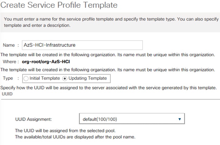
Procedure 2. Storage Provisioning
Step 1. Click Storage Profile Policy tab.
Step 2. In the Storage Profile drop box select RAID-Boot.
Step 3. Click Next.
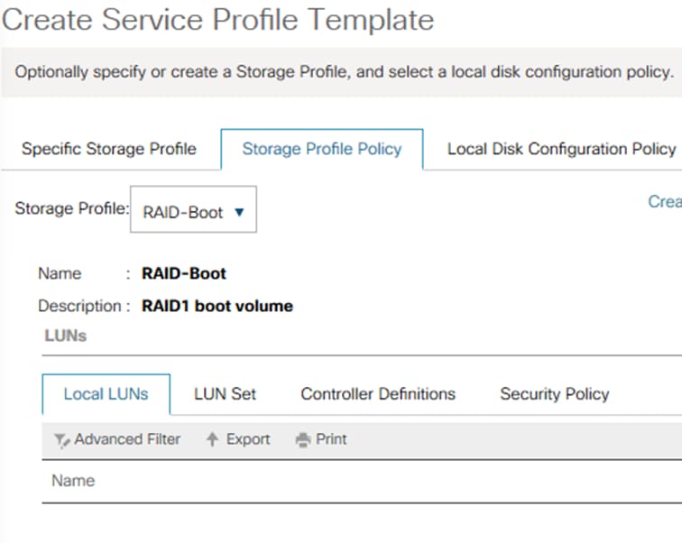
Procedure 3. Create vNICs
Step 1. Select Expert LAN configuration connectivity.
Step 2. Click Add.
Step 3. Enter vNIC name Ethernet-A.
Step 4. Select Use vNIC template.
Step 5. Select vNIC template Ethernet-A.
Step 6. Select Adapter policy Windows.
Step 7. Click OK.
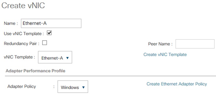
Step 8. Click Add.
Step 9. Enter vNIC name Ethernet-B.
Step 10. Select Use vNIC template.
Step 11. Select vNIC template Ethernet-B.
Step 12. Select Adapter policy Windows.
Step 13. Click OK.
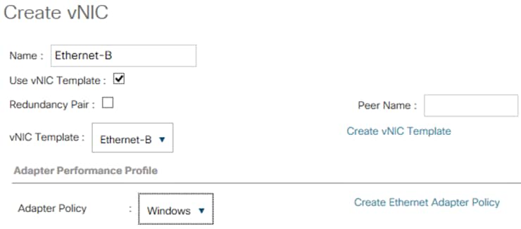
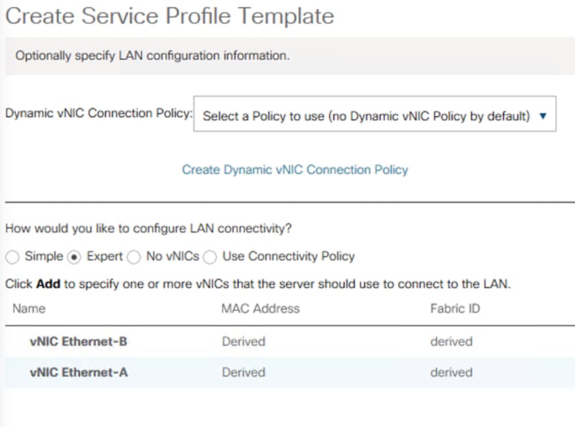
Step 14. Click Next.
Procedure 4. SAN Connectivity Policy
Step 1. Select No vHBAs for the SAN Connectivity Policy.
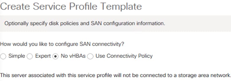
Step 2. Click Next.
Procedure 5. Zoning Policy
Step 1. Leave Zoning information blank and click Next.
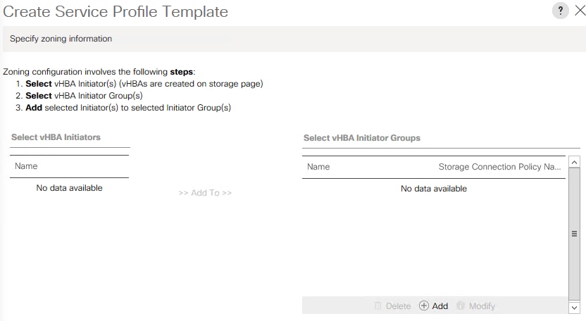
Procedure 6. vNIC Placement
Step 1. No changes are required for vNIC placement. Click Next to continue.
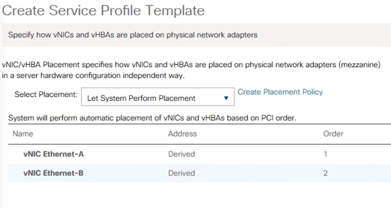
Procedure 7. vMedia Policy
Step 1. No changes are required for vMedia Policy. Click AzS-HCI-C240M5L to continue.
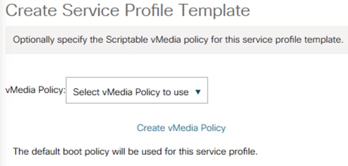
Procedure 8. Server Boot Order
Step 1. Select EmbLUN-DVD-LAN for the Server Boot Order policy and click Next.
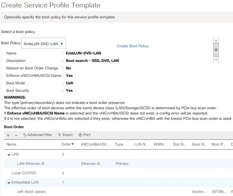
Procedure 9. Maintenance Policy
Step 1. Select UserAck Maintenance Policy and click Next.
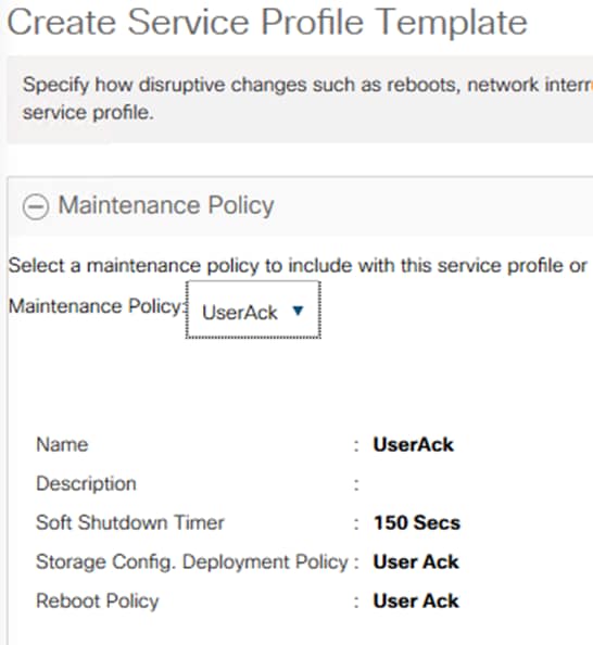
Procedure 10. Server Assignment
Step 1. In the Server Pool Assignment dropdown box select AzureStack-HCI.
Step 2. Set power state to Up.254 In the Server Pool Qualification dropdown box select C240-M5L.
Step 3. Expand Firmware Management by clicking the +.
Step 4. In the Host Firmware Package dropdown box select AzureStackHCI.
Step 5. Click Next.
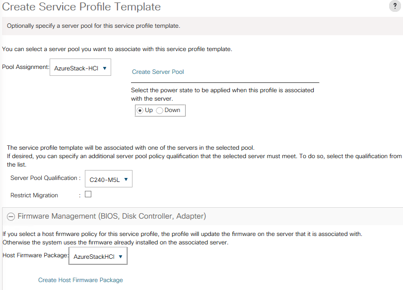
Procedure 11. Operational Policies
Step 1. Expand BIOS Configuration.
Step 2. From the BIOS Policy drop-down list select AzS-HCI-C240M5.
Step 3. Expand Power Control Policy Configuration.
Step 4. From the Power Control Policy drop-down list select NoCap.
Step 5. Expand Scrub Policy.
Step 6. From the Scub Policy drop-down list select NoScrub.
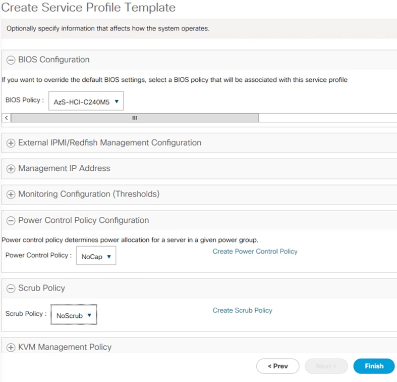
Step 7. Click Finish to create the Service Profile Template.
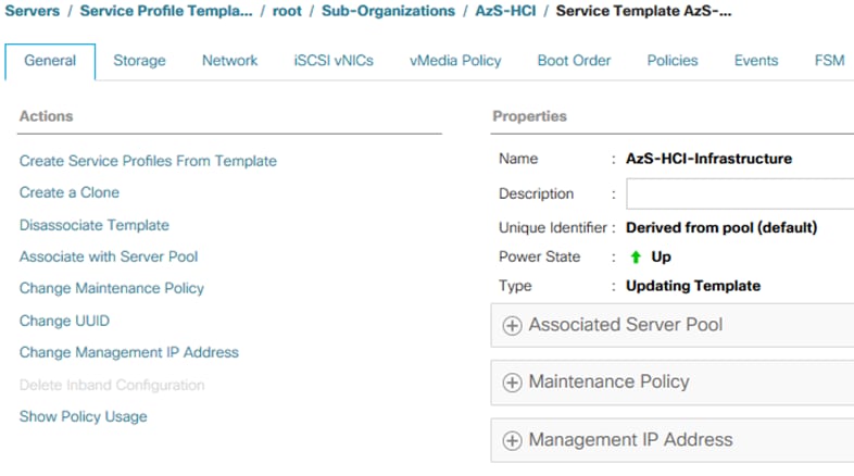
Create Autoconfiguration Policy
Note: The auto configuration policy will automatically create service profiles from the Service Profile template when a server is discovered that meets the qualification policy. The automatically created service profile will be automatically assigned to the discovered server.
Procedure 1. Create the Autoconfiguration Policy
Step 1. Navigate to the Equipment tab in the left column and select the Equipment top-node object.
Step 2. In the right pane, click the Policies tab and select the Autoconfig Policies sub-tab.
Step 3. Click Add.
Step 4. Enter the AzS-HCI-C240-M5L for the Name and add an optional description.
Step 5. Select the previously created Qualification Policy in the Qualification dropdown box.
Step 6. Select the Organization where the Service Profile Template was created in the Org dropdown box.
Step 7. Select the previously created Service Profile Template in the Template Name Dropdown box.
Step 8. Click OK.
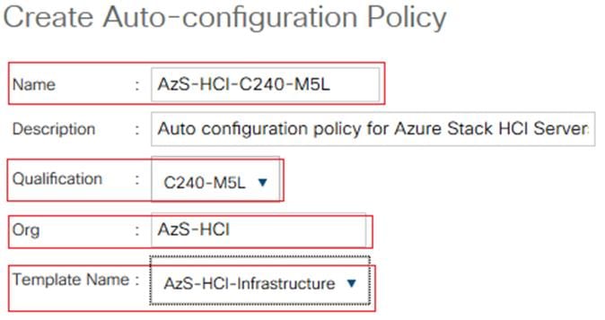
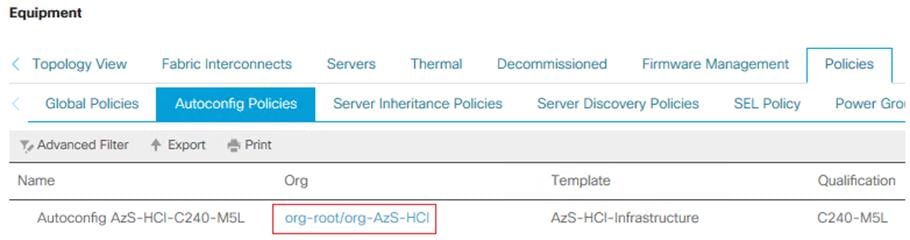
Servers may be renumbering out of order. Servers should be numbers based on their physical position in the rack connection to fabric interconnect port described in the cabling documentation for this solution. Servers should be number based on the following table:
| Server Number |
Path Name |
Adapter Port |
FI Server Port |
| Server 1 |
Path A/1 |
1/1 |
A/1/1 |
| Path B/1 |
1/2 |
B/1/1 |
|
| Server 2 |
Path A/1 |
1/1 |
A/1/2 |
| Path B/1 |
1/2 |
B/1/2 |
|
| Server 3 |
Path A/1 |
1/1 |
A/1/3 |
| Path B/1 |
1/2 |
B/1/3 |
|
| Server 4 |
Path A/1 |
1/1 |
A/1/4 |
| Path B/1 |
1/2 |
B/1/4 |
Procedure 1. Renumber the servers
Note: The server connection to the fabric interconnect port can be identified by checking the VIF path for each server.
Step 1. Select Equipment > Servers > Server 1.
Step 2. In the right pane select the VIF Path tab.
Step 3. Note the VIF Paths and repeat for the remaining servers.
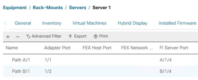
Step 4. Identify the servers with IDs that do not match the FI server port I listed in the table above and decommission them:
a. Select Equipment > Servers > Server 1.
b. Right click Server 1 and select Server Maintenance.
c. Select Decommission and click OK and Yes to confirm.
d. Repeat for remaining servers with the wrong VIF Path.
Note: The serves will disappear from the Servers list in the Equipment tree.
Step 5. Select the Equipment and Decommissioned tab.
Step 6. Expand Rack-Mounts.
Step 7. Double-click on each Server ID number and change it to correspond to the table above.
Step 8. Check the Recommission checkbox next to each server.
Step 9. Click Save Changes to recommission the servers with corrected numbers.
Figure 18. Before Server ID change
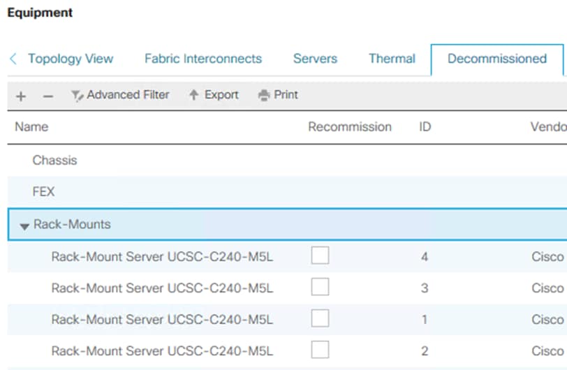
Figure 19. After Server ID Change
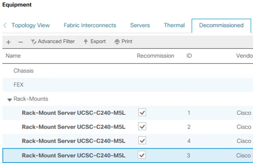
Note: The servers will reappear in the Equipment > Servers tree and server discovery will restart. The services profile created by the auto configuration policy will be associated automatically with the discovered servers once the discovery process completes.

Launch Server KVM Instance to Install the Operating System
Procedure 1. Install the OS by launching the Server KVM Instance
Step 1. Launch KVM to each server after the service profile association is complete. Install the Azur Stack HCI OS 21H2 using PXE boot or a vMedia mapped installation ISO. It is recommended to use PXE boot for OS installation because the installation process will run much faster. Multiple servers can perform OS installation concurrently.
Azure Stack HCI Firmware and Driver Update
This subject explains the firmware and driver update procedure for the Cisco platform for Azure Stack HCI. The following components of Cisco appliance require regular firmware updates to enable latest features and protect from any security threats:
● Cisco UCS Manager
● Cisco UCS Fabric Interconnects
● Cisco UCS Fabric Extenders
● Cisco UCS C-Series Rack-Mount Servers
Note: Cisco recommends performing any firmware upgrade during a scheduled maintenance window.
Prerequisites
The following are required for this update:
● Computer with HTTPS and SSH access to Cisco UCS Manager management endpoint
● From the Cisco Azure Stack HCI download page <Link> download following components corresponding to your Azure Stack build:
◦ Cisco UCS Infrastructure Software bundle
◦ Cisco UCS C-Series Rack-Mount Cisco UCS-Managed Server Software
◦ Cisco Azure Stack OEM Extension pack
Cisco UCS Firmware Upgrade
Procedure 1. Infrastructure (A bundle) Update
Step 1. Run the following PowerShell script on the management host to verify that all network adapters are in the up state. Resolve any adapter state that is not Up.
$nodes = (Get-ClusterNode -Cluster $Cluster).Name
foreach ($node in $nodes) {
Invoke-Command $node -Credential $Creds -scriptblock {
write-host "Host Name:" $env:COMPUTERNAME -ForegroundColor Green
Write-Host " Enabling CredSSP" -ForegroundColor Yellow
$Void = Enable-WSManCredSSP -Role Server -Force
Write-Host "Verifying NIC Port Status " -ForegroundColor Yellow
Get-netadapter | ft Name, InterfaceDescription, Status, MTUSize, MacAddress, LinkSpeed
Write-Host " Disabling CredSSP" -ForegroundColor Yellow
Disable-WSManCredSSP -Role Server
Write-Host " Verifying that CredSSP are disabled on target server..." -ForegroundColor Yellow
Get-WSManCredSSP
}
}
Step 2. Login to the Cisco UCS Manager GUI.
Step 3. Review and resolve any warning, error and critical events logged in Cisco UCS Manager prior to continuing.
Step 4. Verify that port-channel oversale status is Up on both fabric interconnects. Resolve any port-channel states that are not Up.
Figure 20. Fabric A

Figure 21. Fabric B
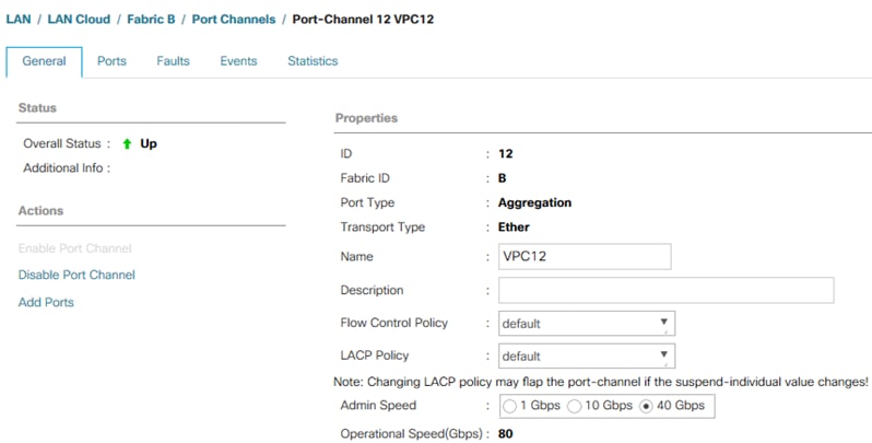
Step 5. Verify that all port channels members membership state is up. Resolve any port channel member whose membership state is not Up.
Figure 22. Fabric A
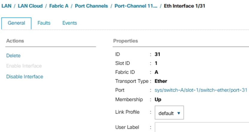
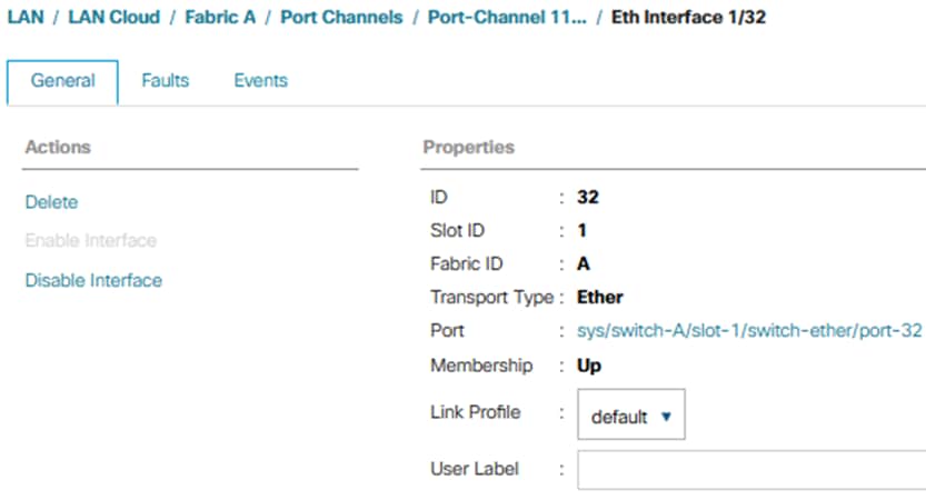
Figure 23. Fabric B

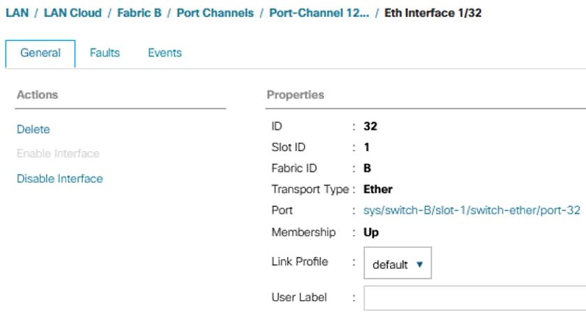
Step 6. Navigate to Equipment > Firmware Auto Install > General tab.
Step 7. Download the Cisco UCS Infrastructure Software Bundle (A bundle) to Cisco UCS Manager.
Step 8. Click Install Infrastructure Firmware and select the infra version to update.
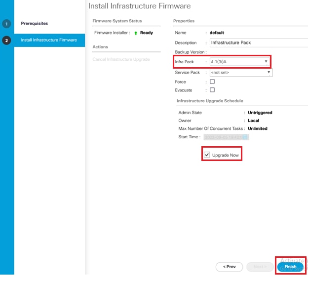
Step 9. Wait for the Cisco UCS Manager update to complete. The Cisco UCS Manager access session will be lost and logging into Cisco UCS Manager again is required.
Step 10. Soon after logging back into Cisco UCS Manager, there will be a pending activity notification in the Cisco UCS Manger portal. (See section Acknowledge Primary Fabric Interconnect Reboot)
Step 11. Wait for the Secondary FI update to finish and Cisco UCS Manager will pop up “User Ack” for the Primary FI update – Do not acknowledge the primary fabric interconnect reboot at this point.
Step 12. Acknowledge the Primary Fabric Interconnect reboot.
Step 13. Verify that the fabric interconnect Fabric A and Fabric B port-channels and port-channel members are Up and in an operation state. See previous section for this procedure. Resolve any failures and warning before continuing to the next step.
Step 14. Verify that all network adapters in the host OS on each cluster node are in the up state. Resolve any adapter state that is not Up before continuing to the next step.
Step 15. Acknowledge the primary fabric interconnect reboot by clicking Reboot now in the pending activities window.
Step 16. When the FI is back online, the infra update will be complete.
Procedure 2. Server firmware (C Bundle) Update
Step 1. Login to Cisco UCS Manager GUI.
Step 2. Navigate to Equipment > Firmware Auto Install > General tab.
Step 3. Download the UCS C-Series Rack-Mount UCS-Managed Server Software (C bundle) to Cisco UCS Manager.
Step 4. Navigate to Server > Policies > root > Host Firmware Packages > AzureStack and click Modify Package Versions.
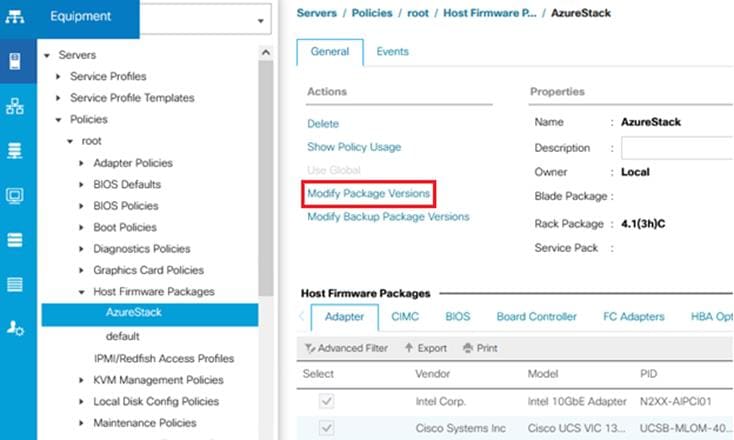
Step 5. Select the downloaded rack package (C-bundle) and click Apply.
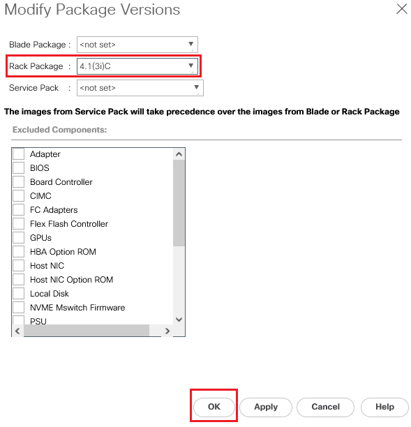
Step 6. Save the changes by clicking yes. Don’t acknowledge the server reboot from the UCS pop-up. The server reboot will be initiated in from the host OS.
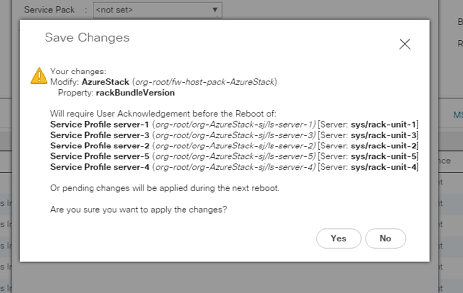
IMPORTANT!: Don’t acknowledge the server reboot from the UCS pop-up. Server reboot will be initiated in from the host OS.
Driver Updated and Host Reboot
Note: The server firmware is staged at this point and will be updated on each server during the server reboot process. Updated drivers need to be added to each server prior to rebooting the servers. It is recommended to verify the cluster health prior to updating the drivers and firmware on the cluster nodes.
Procedure 1. Verify Cluster Health
Step 1. Run the following commands on one of the cluster nodes to verify the cluster health. Review the results and correct all warning and errors.
![]()
Note: AzS-HCI-C01 is the cluster name. This cluster name needs to match your environment.
Procedure 2. Copy Updated Drivers to Each Cluster Node
The drivers can be hosted on a SMB file share and copied to each server node. The following PowerShell commands can be used to copy the drivers to the cluster nodes. These commands need to be executed on each cluster node.
Note: The variables in the following command need to be updated for your environment.
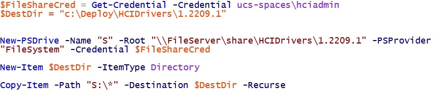
Procedure 3. Install Drivers
Step 1. Drivers are installed using PNPUtil.exe. The following PNPUtile.exe example can be used to install drivers. The path to each inf file needs to be provided. The following command needs to be run for each driver that needs to be update:
pnputil /add-driver c:\Deploy\HCIDrivers\1.2209.1\\Network\QL45412H\NDIS\*.inf /install
Note: Only updated drivers need to be updated using this procedure. Drivers that have not changed in the driver package compared to the drivers that are already running on the server do not need to be updated. PNPUtil will skip adding drivers that are already installed on the system.
PNPUtil.exe documentation can be found here: https://docs.microsoft.com/en-us/windows-hardware/drivers/devtest/pnputil
Procedure 4. Reboot Cluster Nodes
The procedure for rebooting cluster nodes can be found here: https://docs.microsoft.com/en-us/azure-stack/hci/manage/maintain-servers. The cluster nodes need to be rebooted one at a time. Each node must be repaired for reboot, rebooted, and properly bought back online prior to rebooting the next node in the cluster.
Step 1. Verify the virtual disk volume in in a healthy state. Correct any volume that is not in a healthy state:
Get-VirtualDisk | ft FriendlyName, OperationalStatus,HealthStatus
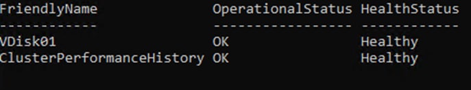
Step 2. Verify that there are no Storage Jobs running. Wait for any running storage jobs to complete:
Get-StorageJob
Note: If the command returns nothing, it means that there are no running storage jobs.
Step 3. Pause and drain the cluster node:
Suspend-ClusterNode -Drain -ForceDrain -Name AZS-HCI-HOST01
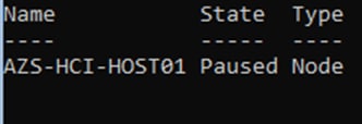
Step 4. Reboot the cluster node:
Restart-Computer -ComputerName AZS-HCI-HOST01 -Force
Step 5. Running the following command on another cluster node will show that the node being rebooted is down. This command can be used to determine when the node that was rebooted comes back up and rejoins the cluster.
Get-ClusterNode
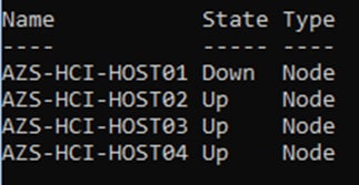
Note: Firmware update progress can be tracked in Cisco UCS Manager in the FSM tab for each server.
Step 6. Resume the cluster nodes after the server boots up:
Get-ClusterNode
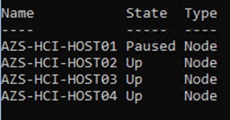
Resume-ClusterNode -Name AZS-HCI-HOST01
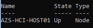
Step 7. Verify that there are no Storage Jobs running. Wait for any running storage jobs to complete:
Get-StorageJob

Step 8. Verify the virtual disk volume in in a healthy state. Correct any volume that is not in a healthy state:
Get-VirtualDisk | ft FriendlyName, OperationalStatus,HealthStatus
Step 9. Repeat steps 1 - 8 for each remaining node.
Procedure 5. Verify Host Firmware Version after Update
Step 1. Login to Cisco UCS Manager and verify “Pending user acknowledge” is cleared and all nodes reboot completed.
Step 2. From Cisco UCS Manager navigate to equipment > Firmware Management > Installed Firmware and verify that all servers are updated to the correct firmware version.
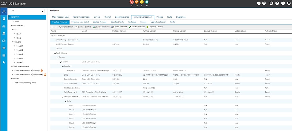
Mike Mankovsky, Principle Engineer, Cisco Systems, Inc.
Mike Mankovsky is a Cisco Unified Computing System Technical Marketing Engineer, focusing on Microsoft solutions that include Azure Stack Hub, Azure Stack HCI, and Microsoft Exchange Server. He has expert product knowledge in Microsoft Windows storage technologies and data protection technologies.
For comments and suggestions about this guide and related guides, join the discussion on Cisco Community at https://cs.co/en-cvds.
CVD Program
ALL DESIGNS, SPECIFICATIONS, STATEMENTS, INFORMATION, AND RECOMMENDATIONS (COLLECTIVELY, "DE-SIGNS") IN THIS MANUAL ARE PRESENTED "AS IS," WITH ALL FAULTS. CISCO AND ITS SUPPLIERS DISCLAIM ALL WAR-RANTIES, INCLUDING, WITHOUT LIMITATION, THE WARRANTY OF MERCHANTABILITY, FITNESS FOR A PARTICULAR PURPOSE AND NONINFRINGEMENT OR ARISING FROM A COURSE OF DEALING, USAGE, OR TRADE PRACTICE. IN NO EVENT SHALL CISCO OR ITS SUPPLIERS BE LIABLE FOR ANY INDIRECT, SPECIAL, CONSEQUENTIAL, OR INCIDENTAL DAMAGES, INCLUDING, WITHOUT LIMITATION, LOST PROFITS OR LOSS OR DAMAGE TO DATA ARISING OUT OF THE USE OR INABILITY TO USE THE DESIGNS, EVEN IF CISCO OR ITS SUPPLIERS HAVE BEEN ADVISED OF THE POSSIBILITY OF SUCH DAMAGES.
THE DESIGNS ARE SUBJECT TO CHANGE WITHOUT NOTICE. USERS ARE SOLELY RESPONSIBLE FOR THEIR APPLICA-TION OF THE DESIGNS. THE DESIGNS DO NOT CONSTITUTE THE TECHNICAL OR OTHER PROFESSIONAL ADVICE OF CISCO, ITS SUPPLIERS OR PARTNERS. USERS SHOULD CONSULT THEIR OWN TECHNICAL ADVISORS BEFORE IMPLE-MENTING THE DESIGNS. RESULTS MAY VARY DEPENDING ON FACTORS NOT TESTED BY CISCO.
CCDE, CCENT, Cisco Eos, Cisco Lumin, Cisco Nexus, Cisco StadiumVision, Cisco TelePresence, Cisco WebEx, the Cisco logo, DCE, and Welcome to the Human Network are trademarks; Changing the Way We Work, Live, Play, and Learn and Cisco Store are service marks; and Access Registrar, Aironet, AsyncOS, Bringing the Meeting To You, Catalyst, CCDA, CCDP, CCIE, CCIP, CCNA, CCNP, CCSP, CCVP, Cisco, the Cisco Certified Internetwork Expert logo, Cisco IOS, Cisco Press, Cisco Systems, Cisco Systems Capital, the Cisco Systems logo, Cisco Unified Computing System (Cisco UCS), Cisco UCS B-Series Blade Servers, Cisco UCS C-Series Rack Servers, Cisco UCS S-Series Storage Servers, Cisco UCS Manager, Cisco UCS Management Software, Cisco Unified Fabric, Cisco Application Centric Infrastructure, Cisco Nexus 9000 Series, Cisco Nexus 7000 Series. Cisco Prime Data Center Network Manager, Cisco NX-OS Software, Cis-co MDS Series, Cisco Unity, Collaboration Without Limitation, EtherFast, EtherSwitch, Event Center, Fast Step, Follow Me Browsing, FormShare, GigaDrive, HomeLink, Internet Quotient, IOS, iPhone, iQuick Study, LightStream, Linksys, MediaTone, MeetingPlace, MeetingPlace Chime Sound, MGX, Networkers, Networking Academy, Network Registrar, PCNow, PIX, PowerPanels, ProConnect, ScriptShare, SenderBase, SMARTnet, Spectrum Expert, StackWise, The Fastest Way to Increase Your Internet Quotient, TransPath, WebEx, and the WebEx logo are registered trade-marks of Cisco Systems, Inc. and/or its affiliates in the United States and certain other countries. (LDW_U1)
All other trademarks mentioned in this document or website are the property of their respective owners. The use of the word partner does not imply a partnership relationship between Cisco and any other company. (0809R)