Molex Implementation Guide
Available Languages
Bias-Free Language
The documentation set for this product strives to use bias-free language. For the purposes of this documentation set, bias-free is defined as language that does not imply discrimination based on age, disability, gender, racial identity, ethnic identity, sexual orientation, socioeconomic status, and intersectionality. Exceptions may be present in the documentation due to language that is hardcoded in the user interfaces of the product software, language used based on RFP documentation, or language that is used by a referenced third-party product. Learn more about how Cisco is using Inclusive Language.
- US/Canada 800-553-2447
- Worldwide Support Phone Numbers
- All Tools
 Feedback
 Feedback
Overview
Power over Ethernet advancements
The IEEE 802.3bt standard has significantly expanded Power over Ethernet (PoE) capabilities beyond its original applications, such as powering wireless access points and IP phones. Cisco’s Universal PoE Plus (UPoE+) switches deliver up to 90 watts of power per port, enabling a wide range of devices to be powered and controlled over an Ethernet infrastructure. This advancement supports innovative use cases, including advanced lighting systems, automated shades, height-adjustable desks, and PoE-powered displays.
Benefits of PoE solutions
The ability to deliver data and PoE offers a flexible, safe, and energy-efficient alternative to traditional high-voltage systems. Key advantages include:
● Energy efficiency: PoE's inherent design allows for dynamic power allocation, ensuring that devices only utilize energy during operation. This contrasts with the static and potentially wasteful power delivery of traditional high-voltage systems.
● Simplified infrastructure: A single Ethernet cable delivers both power and data, reducing installation complexity and costs.
● Sustainability: Simplified PoE solutions eliminate a tremendous amount of steel conduits, a standard for line voltage cabling. This reduces the carbon footprint and contributes to net-zero energy goals by optimizing power consumption and minimizing electrical circuit demands.
● Safety: By employing low-voltage DC power delivery, PoE mitigates many of the electrical safety risks inherent in high-voltage installations.
● Security: A zero-trust security model is embedded into the switch architecture to reduce attack surface and enforce strict access controls.
Architecture and lighting use case validation
Target audience
● project and account managers
● mechanical, electrical, and plumbing (MEP) engineers and partners
● system integrators
● installers, and
● supply chain vendors.
Introduction summary
This implementation guide reflects the engineering alliance between Cisco and Molex, focusing on the advancement of smart building technologies via integrated PoE solutions. Leveraging Cisco's UPoE+ expertise and Molex's CoreSync portfolio, this guide offers practical guidance for the design, deployment, and validation of PoE systems delivering power and data over a single cable.
The guide centers on IEEE 802.3bt advancements, with Cisco UPoE+ switches providing up to 90 watts per port to power diverse devices. It highlights the lighting use case, validating Molex CoreSync gateways, sensors, and harnesses with Cisco Catalyst 9300 switches for efficient, scalable solutions. It also explores applicability to automated shades and environmental monitoring, covering components, architecture, configurations, power calculations, and validation results.
Components used for validation
The components detailed in this section were specifically chosen from the extensive Molex CoreSync and Cisco UPoE+ switching product lines to validate use cases. This represents a small subset of the available products used for this feasibility study.
Molex CoreSync components
This section outlines the individual components manufactured by Molex. The referenced devices are considered first-party products with Cisco product identifiers (PIDs) and stock keeping units (SKUs).
CoreSync management software
Molex uses two components to manage their PoE solutions:
● Molex CoreSync Kube
● Molex CoreSync Edge Controller
You install the Edge Controller application on a virtual machine. It operates a minimum required version of Windows Server 2016 and has these recommended hardware specifications:
● 16 GB of memory
● Any CPU configuration that exceeds a PassMark score of 12,000
● 500 GB of hard disk space
● Fast Ethernet connectivity
The Edge Controller communicates with nodes in the same layer 2 network and supports these parameters:
● 250 lighting zones
● 100 shading zones
● 100 information zones
● 2,500 individually addressable light fixtures
● 12,500 individually addressable sensors that gather data regarding these types of information:
◦ occupancy
◦ ambient light
◦ power draw and consumption
◦ wall-switch and keypad behavior
◦ indoor air quality
◦ temperature
◦ humidity
The Edge Controllers can communicate with Molex CoreSync Kube, which is a single pane-of-glass solution that interfaces with all the Edge Controllers deployed throughout an enterprise network. Kube is deployed on either a virtual machine running Ubuntu Server or a physical appliance with these specifications:
● 24 GB of RAM
● 512 GB of storage
● 12 CPU cores
Modify Kube specifications as PoE solution complexity grows. The specifications provided here are minimums.
After Kube has been commissioned, the CoreSync solution can be managed from Kube, rather than from each individual Edge Controller.
CoreSync Gateway 2.0
The CoreSync Gateway 2.0, a central component of Molex CoreSync’s PoE solutions, connects to the PoE switch with an Ethernet cable. It then powers downstream devices, allocating power according to the Molex Design Tool management software or its default configuration. (For details about this connection, refer to the “Cabling components” section.) The gateways are available in a variety of configurations to meet the needs of the solutions, such as configurations that provide constant current and/or voltage and ones that provide various maximum current values based on voltage.
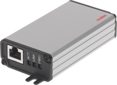
In the validations conducted, the gateway primarily acted as an 802.3bt standards-based PD delivering DC power from the Catalyst 9300 switch to the additional devices downstream in a daisy chain configuration. The gateway selected was in a constant current configuration with a maximum output of 90 watts.
For additional information regarding the CoreSync Gateway 2.0, visit Molex’s product page.
CoreSync Advanced Lighting Sensor
The CoreSync Advanced Lighting Sensor (advanced sensor) is a device with an integrated passive infrared sensor, ambient lighting sensor, and RGB ring. The advanced sensor is capable of being part of a PoE daisy chain, with two connectors that use CoreSync’s 4-pin Micro-Fit connectors to seamlessly connect with other CoreSync devices to receive and send power. The RGB ring can be programmed to react to conditions such as occupancy, reservation, wayfinding beacon, or even air quality.
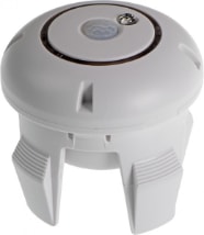
In the validations conducted, advanced sensors were used to act as another load on a daisy chain. They were also used to control lighting by maximizing the load on fixtures in response to input to the PIR sensor.
For additional information regarding the advanced sensor, view Molex’s product page.
CoreSync Air Quality Monitor
The CoreSync Air Quality Monitor is a device with various sensors used to detect these elements:
● carbon dioxide
● particulate matter
◦ PM1
◦ PM2.5
◦ PM10
● total volatile organic compounds
● temperature
● humidity
The air quality monitor also has two 4-pin Micro-Fit connectors with an input and output that enable it to be a member of a CoreSync PoE daisy chain.
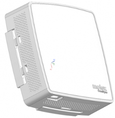
In the validations conducted, the air quality monitor was used as another load in the PoE daisy chain.
For additional information regarding the air quality monitor, view Molex’s product page.
CoreSync harness
Molex PoE solutions are connected from the gateway to downstream end devices via CoreSync harnesses that are terminated with their rugged Micro-Fit 3.0 connectors. The harnesses vary in configuration based on the connection type and cable length. These include:
● 4-pin receptacle
● 4-pin plug
● 4-pin plug panel mount
● 10-pin receptacle
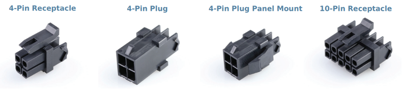
The wiring harnesses are designed to seamlessly integrate with Molex PoE solutions and deliver power in a daisy chain configuration from the factory. This paradigm allows PoE solutions to be flexible, scalable, and modular. This ensures power delivery can meet new and changing requirements.
For additional information regarding CoreSync harnesses, visit Molex’s product page.
Cisco components
This section outlines the individual components manufactured by Cisco. The referenced devices are considered first-party products with Cisco PIDs and SKUs.
Cisco Catalyst 9300 switch
The Catalyst C9300-48H-A switch was provisioned for this validation due to its UPoE+ capabilities. This enables the gateway to fully utilize its potential by negotiating for the full power outlined in the 802.3bt standards.
For additional information regarding the Cisco Catalyst 9300 portfolio of switches, refer to Cisco’s switch data sheet.
The switch runs software version Cisco IOS XE 17.15.2, as indicated in the release notes.
Power supply
The aggregate power budget required by the PoE solution and endpoints primarily governs the selection of a power supply unit for the Catalyst 9300 switch. Power supplies for Cisco Catalyst 9300 switches are available in both alternating current (AC) and DC input configurations, with a spectrum of wattage ratings offered for the AC models.
Power supplies always budget a portion of the total available power for switch hardware and software components. The remaining power is allocated and distributed to PoE endpoints. The system power demands depend on the Catalyst 9300 switch model.
For additional information regarding power supplies for the Catalyst 9300 portfolio of switches, view Cisco’s data sheet.
Power budget calculation
In the Catalyst 9300 switch data sheet, Table 4 provides the power available for PoE with the matching power supply configuration. When designing the PoE-based power delivery architecture, consider these factors when selecting the switch model and power supplies:
● How many switch interfaces will be providing PoE power?
● What is the PoE class for each PoE endpoint?
● What is the total power requirement for all connected devices, including the Catalyst switch itself and the PoE-powered solutions to achieve the desired outcome?
● What is the highest power that the PoE solution can draw under normal and maximum loads?
● How will the total available power be distributed to each interface based on PoE endpoint class?
● How many switches will be required to meet the total power requirement?
● Is redundancy required?
● Is the system scalable for immediate future needs?
In addition to these factors, applicable building regulations, standards, and codes influence the overall system design. Designing the PoE network requires strong collaboration. This ensures DC PoE power is effectively distributed to realize maximum value and achieve optimal efficiency, while remaining compliant with all regulations for safe operation.
This section outlines the cables used when connecting the gateways to the Catalyst C9300-48H switch.
22AWG Cat5e Ethernet cables
Many cable manufacturers optimize Ethernet cables for PoE power delivery based on 802.3bt standards. Thicker 22AWG cables minimize power loss over the connection length. In this setup, two Cat5e cables measuring 5 meters and 100 meters in length were tested. The 5-meter cable demonstrated a shorter homerun with near-zero power loss. The 100-meter cable demonstrated homerun viability at the maximum length governed by 802.3bt standards.
23AWG Cat6 Ethernet cables
To reflect the more commonplace brownfield deployments of existing network infrastructures, Cat6 cables were also chosen to validate the use cases. These tests aimed to verify that these preexisting infrastructures could deliver the power necessary to enable UPoE+ use cases, avoiding the need for new cabling. As with the Cat5e cables, two Cat6 cables (one 5 meters long and another 100 meters long) were used for these tests.
Reference architecture
This section outlines the reference architecture used to conduct tests.
High-level diagram of PoE network
The required components present in all tests are:
● CoreSync Edge Controller
● Power sourcing equipment (PSE)—in this case, the Cisco Catalyst C9300-48H switch
● CoreSync Gateway 2.0
This diagram shows the shared connectivity architecture. The gateway is enlarged to represent the homerun connection to the PSE.
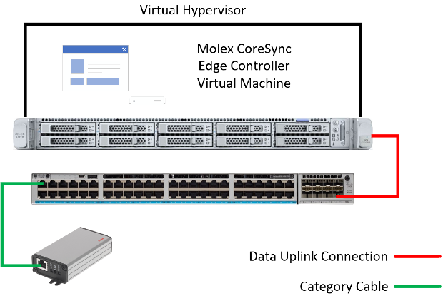
The data uplink connection between the Hypervisor and network switch can be either a copper or fiber connection. The physical medium used to connect the management software to the network is irrelevant. To oversee and manage the PoE solution, the only requirement is the ability to communicate using IP addresses.
Validation methodology
Functional operation
To validate the functional operation, the lighting solution should behave as programmed. It should turn on at full brightness to maximize the load on the gateway. It should also turn off after three minutes to minimize the load. The intent of the validation is to ensure that the gateways successfully deliver power to the end devices to meet 802.3bt compliance.
Catalyst 9300 switch PSE operational state
Use the Catalyst 9300 switch command line interface to confirm that the switch allocates and delivers the required power to the PoE solution. There are several commands you can enter, but to validate power delivery, the show power inline GigabitEthernet X/X/X detail command provides the near real-time power draw on the interface.
This command’s output provides these insights:
● PoE configuration and status
● Power allocation and consumption
● Power negotiation
● PoE capabilities and features
● PoE interface counters and statistics
These outputs provide tremendous value for confirming actual power draw and help to effectively design and operate the PoE infrastructure.
Here is a sample of the output of the command:
Access9300#show power inline gigabit 1/0/29 detail
Interface: Gi1/0/29
Inline Power Mode: auto
Operational status (Alt-A,B): on,on
Device Detected: yes
Device Type: Ieee PD
Connection Check: SS
IEEE Class (Alt-A,B): 8
Physical Assigned Class (Alt-A,B): 8
Discovery mechanism used/configured: Ieee and Cisco
Police: off
Power Allocated
Admin Value: 90.0
Power drawn from the source: 90.0
Power available to the device: 90.0
Allocated Power (Alt-A,B): 90.0
Actual consumption
Measured at the port(watts) (Alt-A,B): 18.8
Maximum Power drawn by the device since powered on: 19.0
Absent Counter: 0
Over Current Counter: 0
Short Current Counter: 0
Invalid Signature Counter: 0
Power Denied Counter: 0
Power Negotiation Used: IEEE 802.3bt LLDP
LLDP Power Negotiation --Sent to PD-- --Rcvd from PD--
Power Type: Type 2 PSE Type 2 PD
Power Source: Primary PSE
Power Priority: high critical
PD 4PID: 0 0
Requested Power(W): 71.3 71.3
Allocated Power(W): 71.3 71.3
Requested Power ModeA(W): 0.0 0.0
Allocated Power ModeA(W): 0.0 0.0
Requested Power ModeB(W): 0.0 0.0
Allocated Power ModeB(W): 0.0 0.0
PSE Powering Status: 4 pair SS PD Ignore
PD Powering Status: Ignore SS PD
PSE Power Pair ext: Both Alternatives Ignore
DS Class Mode A ext: SS PD Ignore
DS Class Mode B ext: SS PD Ignore
SS Class ext: Class 8 Class 8
PSE Type ext: Type 4 PSE Type 4 SS PD
PSE Max Avail Power: 71.3 0.0
PSE Auto Class Supp: No No
PD Auto Class Req: No No
PD Power Down Req: No No
PD Power Down Time(sec): 0 0
Four-Pair PoE Supported: Yes
Spare Pair Power Enabled: Yes
Four-Pair PD Architecture: Shared
Perpetual POE Enabled: TRUE
Fast POE Enabled: TRUE
This output confirms that the switch successfully negotiates with the gateway to allocate the desired power for PoE and shows the actual power draw at the time the command was executed.
Additional information regarding the commands for software version 17.15.2 can be found here.
Catalyst 9300 switch
This section provides the configurations implemented on the switch.
Global switch configurations
On a Cisco switch, global configurations apply to the entire switch, rather than a specific interface or feature.
This section provides the recommended global configurations for Cisco switches.
Step 1. Enable LLDP.
configure terminal
lldp run
Step 2. Enable CDP.
CDP provides basic PoE power negotiation and dynamic updates (similar to those provided by LLDP).
configure terminal
cdp run
Step 3. Configure a VLAN for the PoE network.
configure terminal
vlan 104
description Molex PoE network
Step 4. Configure the interface VLAN/SVI.
configure terminal
interface vlan 104
description Molex CoreSync
ip address 10.254.17.50 255.255.255.240
These configurations placed the CoreSync devices in Vlan 104 with a 10.254.17.48/28 IP network. The configurations documented here are essential for the CoreSync solution to operate with power and data connectivity. Other configurations such as high availability and security can be added based on the overall network design.
For the gateways to communicate with the CoreSync Edge Controller, they must be assigned IP addresses. In this validation, per-port IP address assignment was used. The switch acted as the DHCP server, and any device connected to a configured interface received the same IP address.
Step 5. Configure the IP DHCP scope.
configure terminal
ip dhcp pool Molex_Lights
network 10.254.17.48 255.255.255.240
address 10.254.17.53 client-id "Gi1/0/27" ascii
address 10.254.17.54 client-id "Gi1/0/28" ascii
address 10.254.17.55 client-id "Gi1/0/29" ascii
address 10.254.17.56 client-id "Gi1/0/30" ascii
Step 6. Configure interfaces to use parameters configured in the DHCP pool.
configure terminal
interface range GigabitEthernet 1/0/27-30
switchport mode access
switchport access vlan 104
ip dhcp server use subscriber-id client-id
LLDP considerations
Ensure LLDP is running and operational. This allows a gateway connecting to the switch to negotiate for the allocation of all 90 watts of power to the connected interface.
To validate successful negotiations, enter the show lldp neighbor GigabitEthernet X/X/X detail command for the desired interface.
Here is sample output for the command after successful negotiation.
Access9300#show lldp neigh gig 1/0/28 detail
------------------------------------------------
Local Intf: Gi1/0/28
Local Intf service instance: -
Chassis id: 6827.19c0.f02c
Port id: port0
Port Description: VENDOR: MOLEX; MODEL: GW 90W 802.3bt; LABEL:
System Name: CoreSync
System Description:
sysDescr.0 = STRING: <<Port_Desc: VENDOR: MOLEX; MODEL: GW 90W 802.3bt; LABEL: ; HW_REV: E; FW_REV: 1.7.13>>
Time remaining: 99 seconds
System Capabilities: O
Enabled Capabilities: O
Management Addresses:
IP: 10.254.17.54
Auto Negotiation - supported, enabled
Physical media capabilities:
100base-TX(FD)
100base-TX(HD)
10base-T(FD)
10base-T(HD)
Media Attachment Unit type - not advertised
Vlan ID: - not advertised
Peer Source MAC: 6827.19c0.f02c
UPOE/UPOE+ Power-via-MDI TLV:
Power Pair: Ignore
Power Class: Class 8
Power Device Type: Type 4 SS PD
Power Source: PSE
Power Priority: critical
Power Requested: 71300 mW
Power Allocated: 71300 mW
MED Information:
MED Codes:
(NP) Network Policy, (LI) Location Identification
(PS) Power Source Entity, (PD) Power Device
(IN) Inventory
H/W revision: E
F/W revision: 1.7.13
S/W revision: 1.1.11
Serial number: 10000000
Manufacturer: MOLEX
Model: GW 90W 802.3bt
Asset id: 00330219
Capabilities: PD, IN
Device type: Endpoint Class I
Network Policies - not advertised
PD device, Power source: PSE, Power Priority: Critical, Wattage: 71.3
Location - not advertised
Total entries displayed: 1
Cisco recommended switch features to consider
Cisco’s Catalyst 9300 switches have features developed for Smart Buildings and PoE specific use cases, with many being specifically aimed at optimizing and enhancing PoE solutions. This section outlines a few of these features.
Cisco Discovery Protocol
Cisco Discovery Protocol (CDP) automatically discovers and shares information about other directly connected CDP-capable devices. This simplifies network setup and management, as there is no need to manually configure neighboring devices. Once a CDP-capable device is powered on, it automatically starts sending CDP packets out of every active interface. It provides the connected Cisco Catalyst switch with information about the manufacturer, computer model, IP address, MAC address, and version.
Molex CoreSync devices currently do not support CDP.
Additional information regarding CDP is available here.
Stackpower
Cisco StackPower, a key feature of the Catalyst 9300 Series switch, enables the aggregation of power from the operating power supplies of up to four stacked switches into a larger, unified power pool. This resource provides redundancy, ensuring that a switch and its connected PoE devices remain operational despite a catastrophic power supply failure within the stack.
Without StackPower, a failed power supply may drastically reduce available PoE power.
For example, if a standalone Catalyst C9300-48H switch has two 1,100-watt power supplies, it has 1,922 watts available for PoE power. If the switch is deployed in a PoE lighting solution with 15 interfaces using 90 watts, the solution requires 1,350 watts for PoE. A single power supply would be insufficient, leading to power shedding (where the switch cuts power to some interfaces to remain operational).
However, if StackPower is implemented, and the switch belonged to a stack with another switch that also had two 1,100-watt power supplies, the total available power to the solution would be 4,400 watts. If both switches had the same PoE load, the combined PoE power requirement would be 2,700 watts. If a single power supply on either switch failed, the remaining three power supplies in the stack would be more than enough to keep both PoE lighting solutions operational.
Additional information regarding StackPower is available here.
Port priority
On Cisco Catalyst switches, PoE port priority allows network admins to configure how PoE power is allocated among a switch’s ports when the switch's total power budget has been exceeded.
In the event of power shedding, the switch prioritizes its system power and PoE interfaces. Interfaces with low priority (the default value) are turned off first. To ensure critical devices remain operational despite component failure, configure their port priority to high.
configure terminal
interface GigabitEthernet X/X/X
power inline port priority high
By assigning an interface with high priority, you instruct the switch to prioritize the allocation of available PoE power to all interfaces with high priority first.
show power inline priority
Interface Admin Oper Admin
State State Priority
---------- ------ ---------- ----------
Gi1/0/1 auto on high
Gi1/0/2 auto off low
Gi1/0/3 auto off low
Gi1/0/4 auto off low
Gi1/0/5 auto off low
Gi1/0/6 auto off low
Gi1/0/7 auto off low
Gi1/0/8 auto off low
Gi1/0/9 auto off low
Gi1/0/10 auto off low
Gi1/0/11 auto off low
Perpetual PoE
Perpetual PoE is a feature that keeps power on the PoE port on during an admin-triggered switch reload. While reloading, the switch must remain connected to a power source. If a switch loses power, perpetual PoE does not work.
To enable perpetual PoE on the desired interfaces, enter these commands:
configure terminal
interface GigabitEthernet X/X/X
power inline port perpetual-poe-ha
Fast PoE
In conjunction with perpetual PoE, fast PoE can be configured to allow faster PoE recovery times in the event of a power failure. When fast PoE is applied to an interface, the switch enables and allocates PoE power as soon as power is restored after a power loss. This allows the connected powered device to receive DC power based on its previously negotiated power levels. It does not wait for the system to come up and complete the 802.3af/at/bt detection process.
Note: For interfaces exceeding 30 watts, power allocated at initial power-on is capped. The powered device and switch must negotiate for power, so full allocation occurs only after the software is fully operational and negotiations have completed.
To enable fast PoE on the desired interfaces, enter these commands:
configure terminal
interface GigabitEthernet X/X/X
power inline port perpetual-poe-ha
power inline port poe-ha
Note: To enable fast PoE on an interface, perpetual PoE must first be configured on the Cisco switch. If perpetual PoE is not enabled, the administrator is prompted to enable it.
Additional information regarding perpetual and fast PoE can be found here.
Gateway management considerations
The gateways provide a static amount of wattage and turn on the lighting components of the PoE solution, such as any lighting fixtures that are connected and the LED ring on the Advanced Sensor. The wattage cannot be changed. While devices turn on, they must be commissioned via a Molex CoreSync Edge Controller for control. This allows the modification of their behavior using control devices such as wall switches and sensors.
CoreSync commissioned PoE solution
Commissioning the Molex CoreSync PoE solution with Edge Controllers and Kube enables several use cases and benefits. These include
● smart building control, monitoring, and reporting
● energy saving features to reduce PoE idle power consumption
● APIs to interface with third-party applications and devices
● programming automation and behavior based on collected data, and
● a single-pane facilities management solution to manage buildings.
Outcome of validations
This section outlines the use cases tested and the outcomes of those tests.
Lighting
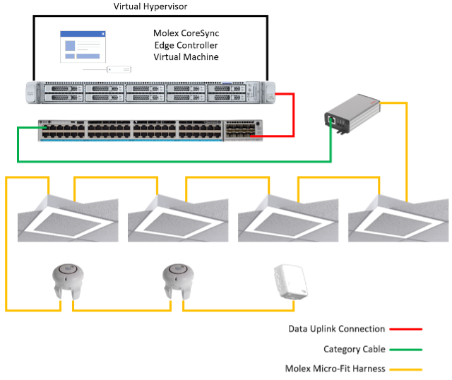
Table 1. Bill of materials for lighting use case
| Cisco product ID |
Description |
Quantity |
| C9300-48H-A |
Cisco Catalyst 9300 Series switch with 48 UPoE+ interfaces and the DNAC Advantage license |
1 |
| PWR-C1-1900WAC-P |
1,900-watt power supply for the Catalyst 9300 Series switch |
1 |
| Molex product ID |
Description |
Quantity |
| 180798-1000 |
Constant current 90-watt PoE gateway |
1 |
| 182089-2000 |
Advanced Lighting Sensor |
2 |
| 1820894000 |
Air Quality Monitor |
1 |
| A4 |
B4 |
C4 |
The lighting fixtures were third-party fixtures that were fitted with Molex drivers to seamlessly integrate them into the PoE lighting solution. Each of the fixtures were rated for 15 watts.
In the diagram, the gateway has a single homerun, and these devices are daisy-chained in sequential order:
● 4 x 15 watt lighting fixtures
● 2 x advanced sensors
● 1 x air quality sensor
In total, seven Micro-Fit harnesses were used to establish this lighting solution.
Variables altering power draw for lighting use case
The variable that impacts PoE lighting solutions the most is the brightness of the fixtures. The brighter the lights are, the more power that’s drawn from the PSE.
The advanced sensor was used to adjust the power draw up and down as necessary. For this validation, the minimum and maximum power draw were measured to determine the minimum operational power draw and a determine the worst-case scenario.
Power draw results for PoE lighting
Note: Due to fluctuations in power draw readings, the displayed numbers are an average of readouts from the “show power inline interface detail” command, collected every minute for five minutes.
This table displays the results of test cases when connecting the gateway to the PSE with a Cat5e 22AWG cable of the listed length and brightness setting of the lighting fixtures.
Table 2. Power draw results with Cat5e 22AWG homerun
| Homerun length (m) |
Fixture brightness setting |
Average power draw (W) |
| 5 |
Minimum |
2.9 |
| 5 |
Maximum |
65.4 |
| 100 |
Minimum |
2.9 |
| 100 |
Maximum |
66.0 |
This table displays the results of test cases when connecting the gateway to the PSE with a Cat6 23AWG cable of the listed length and brightness setting of the lighting fixtures.
Table 3. Power draw results with Cat6 23AWG homerun
| Homerun length (m) |
Fixture brightness setting |
Average power draw (W) |
| 5 |
Minimum |
2.8 |
| 5 |
Maximum |
67.1 |
| 100 |
Minimum |
2.9 |
| 100 |
Maximum |
66.6 |
Use case conclusion
The tests showed that the gateway successfully delivered all the wattage necessary to turn on the four fixtures and connected devices. The load of the entire solution was not enough to exceed the maximum of 71.3 watts outlined in the 802.3bt standards, but the gateway was successful in meeting its objective.
The PSE successfully delivered power across both Cat5e and Cat6 cables. This shows that an optimally placed PSE can provide illumination across a large square footage of space with gateways installed using cables that are 100m long.
Conclusion
The validation tests confirm that Cisco’s UPoE+ switches effectively deliver up to 90 watts of power to the CoreSync Gateway 2.0, enabling DC power distribution to a diverse range of connected devices. This integration of the Molex CoreSync portfolio with Cisco’s PoE infrastructure demonstrates the versatility and efficiency of PoE-based smart building solutions.
Test results and supported use cases
Comprehensive testing of the CoreSync Gateway 2.0 showcases its ability to power multiple device types through a single gateway, supporting a variety of smart building applications. Devices successfully powered during the validation include
● light fixtures
● environmental sensors, and
● control devices.
These results represent only a subset of the potential applications, as the CoreSync Gateway 2.0 can deliver DC power to a broad array of devices. This unlocks extensive possibilities for smart building deployments.
Molex CoreSync portfolio capabilities
The Molex CoreSync portfolio plays a pivotal role in the engineering alliance with Cisco, delivering integrated PoE solutions for smart buildings. Paired with Cisco's UPoE+ switches, such as the Catalyst 9300 Series switch, CoreSync enables efficient power and data delivery over a single Ethernet cable, adhering to IEEE 802.3bt standards for up to 90 watts per port. This supports energy efficiency, simplified infrastructure, sustainability (for example, reduced steel conduits), and safety via low-voltage DC power.
Core components and management
● Management software: CoreSync includes the Edge Controller, deployed on a Windows Server 2016+ virtual machine with minimum specifications (16 GB RAM, CPU exceeding PassMark 12,000, and 500 GB storage). It manages up to 250 lighting zones, 100 shading and information zones, 2,500 addressable light fixtures, and 12,500 sensors within a Layer 2 network. These sensors gather data on occupancy, ambient light, power consumption, wall-switch and keypad behavior, indoor air quality (IAQ), temperature, and humidity. The Kube platform, on an Ubuntu Server (minimum 24 GB RAM, 512 GB storage, and 12 CPU cores), offers centralized management scalable to enterprise needs.
● Gateway 2.0 (PID: 180798-1000): The Gateway 2.0 connects to Cisco UPoE+ switches via Ethernet. It distributes up to 90 watts of DC power to downstream devices in daisy-chain configurations. The Gateway 2.0 is available in constant current and voltage variants. It supports flexible power allocation via the Molex Design Tool, powering lighting, shades, and sensors with two-way communication.
● Advanced Lighting Sensor (PID: 182089-2000): The Advanced Lighting Sensor features passive infrared (PIR) for occupancy detection, ambient light sensing, and a programmable RGB ring for status indicators (use for wayfinding). The sensor daisy-chains via 4-pin Micro-Fit connectors, enabling lighting control and load adjustment.
● Air quality monitor (PID: 182089-4000): The Air Quality Monitor measures CO2, particulate matter (PM1/2.5/10), total volatile organic compounds (TVOCs), temperature, and humidity. It is daisy-chain compatible via 4-pin Micro-Fit connectors and supports IAQ monitoring.
● Harnesses (PID: CSH-XYZZ-AA): Harnesses are rugged Micro-Fit 3.0-terminated cables (4-pin receptacle/plug/panel mount or 10-pin). They facilitate modular daisy-chaining from gateways to devices, ensuring scalability and flexibility.
Integration and validation
The guide validates CoreSync with Cisco Catalyst 9300-48H-A switches (IOS XE 17.15.2), using 22AWG Cat5e and 23AWG Cat6 cables up to 100 meters long. In the lighting use case, a 90W gateway powers four 15W fixtures, two advanced sensors, and one air quality monitor, drawing 2.8-67.1W (based on brightness and cable type) within 802.3bt limits. Configurations include VLANs (for example, 104), LLDP/CDP for power negotiation, and DHCP for IP assignment. The Molex website highlights CoreSync's IoT focus, with Cisco UPoE+ compliance ensuring reliable power delivery. This is demonstrated in deployments like Cisco's PENN1 building, enhancing lighting and environmental control.
Strategic impact
The collaboration between Cisco and Molex on PoE technologies offers practical advantages for smart building deployments, focusing on improved energy management and infrastructure simplification. By integrating Cisco's UPoE+ switches with Molex's CoreSync products, building operators can reduce energy use through dynamic power allocation and consolidated cabling. This supports sustainability efforts like lower carbon emissions and alignment with net-zero objectives.
This alliance facilitates reliable systems for lighting, environmental monitoring, and other applications, helping to cut installation costs and enhance building functionality in sectors such as offices and healthcare. Overall, it provides a solid foundation for scalable, IoT-enabled environments that promote operational efficiency and occupant well-being without overhauling existing setups.
Reference use cases
Cisco has a long history of deploying Molex solutions into its own real estate portfolio. Two of the latest projects are discussed here:
● PENN1