Understanding Cisco StackPower White paper
Available Languages
Bias-Free Language
The documentation set for this product strives to use bias-free language. For the purposes of this documentation set, bias-free is defined as language that does not imply discrimination based on age, disability, gender, racial identity, ethnic identity, sexual orientation, socioeconomic status, and intersectionality. Exceptions may be present in the documentation due to language that is hardcoded in the user interfaces of the product software, language used based on RFP documentation, or language that is used by a referenced third-party product. Learn more about how Cisco is using Inclusive Language.
Businesses require a highly available campus network. Network switch power redundancy is a critical component of overall campus redundancy. Cisco® StackPower is an innovative feature that aggregates all the available power in a stack of switches and manages it as one common power pool for the entire stack. This helps customers achieve more granular control over power use, resulting in savings that reduce the Total Cost of Ownership (TCO) of Cisco Catalyst® switches.

Cisco StackWise® 480 and Cisco StackPower connectors
This white paper focuses on the Cisco StackPower architecture and covers the following:
● Benefits of Cisco StackPower
● Technology overview
● Cisco StackPower operation
◦ StackPower budgeting
◦ Adding a new switch to a power stack
◦ Zero-footprint RPS
● Use cases of Cisco StackPower
● Intelligent power management
● Cisco StackPower topology
● Modes of operation
● Intelligent load shedding
● Best practices
Benefits of Cisco StackPower technology
The benefits of Cisco StackPower technology are immediately tangible, and so are the savings. Consider a stack of switches, with each switch requiring a slightly higher power budget for some extra Power over Ethernet (PoE) devices randomly scattered in the stack. Purchasing an extra second power supply for each switch that needs additional power would be inefficient and expensive. With the Cisco StackPower solution, a common pool of power is made available, and additional power can automatically be redirected to the appropriate switch based on the available power budget in the common power pool.
Cisco StackPower technology immediately produces savings by reducing the number of power supplies required per switch and the number of outlets required in the wiring closet. Additional savings accrue from minimizing energy waste due to inefficiency of power-supply operation at lower loads and reducing cooling requirements in the wiring closet. The technology also eliminates the need for external power shelves, thus freeing up additional space and power outlets in the wiring closet.
Cisco StackPower also allows the deployment of larger power pools by using a Cisco Expandable Power System 2200 (XPS 2200). This system allows for a star topology that shares power with up to eight switches. For details, see “Cisco StackPower Topology” section.
Cisco StackPower technology provides the following additional benefits:
● Abstracts the location of a power supply from its physical location in a stack of switches, allowing for better use of available power capacity
● Maximizes the efficiency of power supplies: Aggregated loads allow power supplies to operate at optimum efficiency, considerably reducing the waste of power over time
● Provides or complements the power required for PoE+ and Cisco Universal POE (Cisco UPOE®) to any port in a stack
● Enables a scalable PoE+ and Cisco UPOE infrastructure
● Offers a pay-as-you-grow architecture, similar to Cisco StackWise technology
● Offers improved reliability, availability, and efficiency with the XPS 2200 serving to up to eight switches
● Enables a “zero-footprint” Redundant Power System (RPS)
● Offers greater redundancy with the RPS:1+N vs. 1:N redundancy
● Allows offlining of power supplies when extra capacity is available in the system
● Lowers TCO by reducing the number of power supplies needed, the number of devices in the rack, the amount of heat in the wiring closet, and the number of AC outlets in the wiring closet
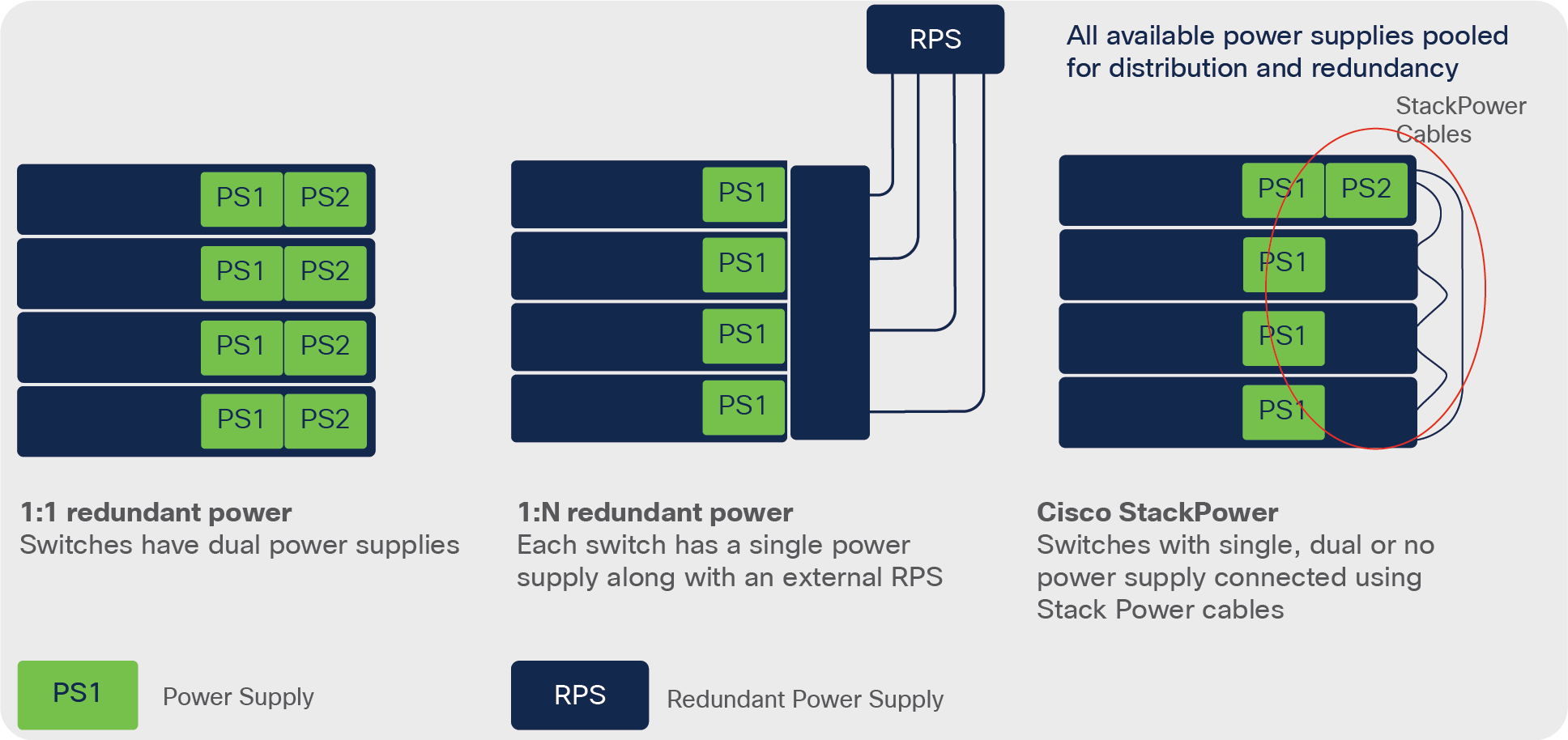
There are two commonly used power redundancy solutions for switches – full redundancy and partial redundancy. In full redundancy, every switch is attached to two power supplies, so that if one goes down, the other takes over. This scheme is also called 1:1 redundancy. In partial redundancy, there is one extra power supply for multiple switches. This is also called 1:N redundancy. Each has its drawbacks.
Fully redundant power solutions (1:1) are often underutilized because every switch has a backup power supply that is idle under normal conditions. However, partially redundant power solutions (1:N) take time to come online in the event of a power failure leading to an outage.
Cisco StackPower provides a revolutionary alternative to power redundancy for the Cisco access switches. It pools the available power supplies from all the switches and makes the pooled power available to all of them. The pooling of the power supplies is the most efficient way to distribute power to all the switches equally, because any switch can use the power from the pool, and if a power supply fails, excess power from the pool can be redistributed to the affected switch in no time.
Figure 2 shows the different types of power redundancy.
Ways of providing redundant power
A key aspect of the Cisco StackPower technology is the way power is supplied and distributed to a switch in the stack.
Cisco StackPower technology represents a new approach to power supply design and power distribution in a switch, but its effects and results are seen most significantly in a stack of switches.
The ability to manage power as a shared resource is unique to a stack of switches that can operate as a single unit. Note that all power available in the power stack is combined into a single large pool of power, and the stack becomes a large single load to the power pool. Figure 3 demonstrates this concept.
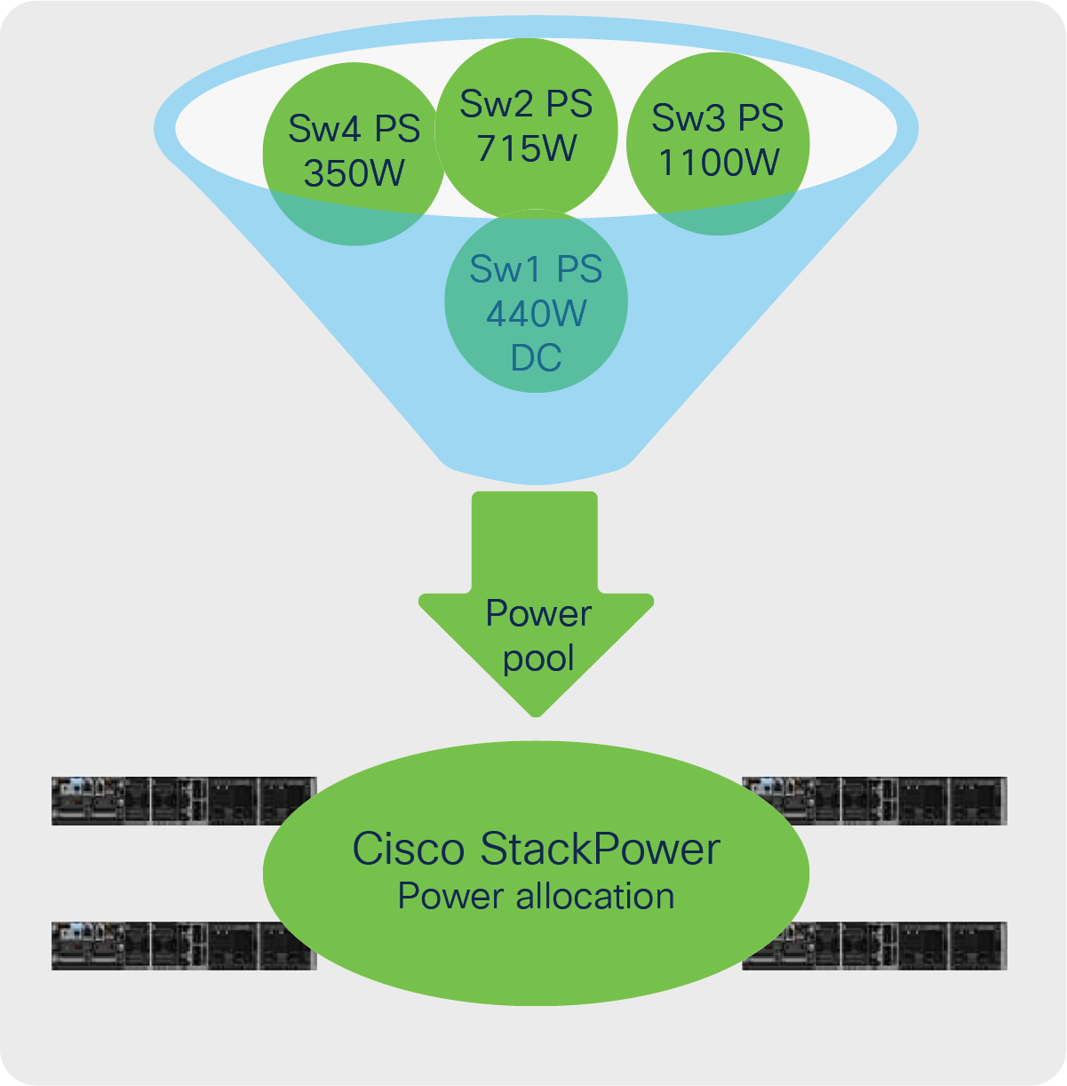
Cisco StackPower technology: One power pool, one load
A surplus of power in a power stack enables features such as zero-footprint RPS and 1+N redundancy instead of 1:N redundancy with a dedicated external RPS.
Redundancy with Cisco StackPower technology is better than traditional(1:N) redundancy, because the redundant power supply is already inline (1+N) as opposed to being switched from one source to another, as is done with a classic redundant power supply (1:N). The 1+N redundancies are less susceptible to problems because the power is already available inline.
The primary function of the StackPower circuitry is to maintain safe distribution of power from the Input Power supplies to all of the various loads. In typical power architectures, when a power supply goes over its limit for more than a few microseconds – it simply shuts down.
One of the first issues to understand within the StackPower architecture is how this balance is maintained between the power available from the Input Power Supplies (e.g., PWR-C1-1100WAC) and all the various loads (e.g., Switching circuitry, PoE loads). In StackPower, this balance is maintained through a task known as the StackPower budgeting algorithm, which is at the core of both the general operation of StackPower and is also integral to its resiliency and redundancy.
When the balance goes negative, it is the job of the Budgeting Algorithm to notify what is known as Intelligent Load Shedding Algorithm (Discussed in Intelligent Load Shedding Section) to restore the balance. It does so, as its name implies, by “shedding” loads (based on user programmable priorities) until the balance is restored.
This section describes the operational details of how Power Stacks are formed and maintained using the Budgeting Algorithm as well as how redundancy and resiliency are implemented using Load Shedding.
StackPower budgeting
Budgeting is integral to the operation of StackPower. Budgeting is required to maintain a balance between the available input power and the various loads.
Budgeting Terminology
Before getting into the details of how StackPower Budgeting works, there is a need to define some new terminology:
● Input power – the aggregate of all of the Input Power supplies (e.g., PWR-C1-1100WAC).
● Allocated power – the aggregate of the all Worst-Case power that could be consumed by all of the circuitry (Switches, StackPower, and PoE). Note that this does not include the Reserved Power.
● Unused power – the difference between the Allocated and the Input Power. The Unused Power, for example, is available to be allocated as PoE when new PDs are attached to a switch.
● Actual power – the power that is actually being drawn from all of the combined circuitry.
● Redundant power – power set aside in Redundant Mode, equal to the rating of the largest supply installed in the Power Stack, to ensure no service disruption in the event of a single Input Supply outage.
● Reserved power – all of the power reserved for functions other than Switches, Infrastructure, and PoE – which is to say the Overhead Power and the Redundant Power.
● Maximum switch power consumption – the power allocated for the entire System (Switch plus StackPower infrastructure).
● Overhead power – the power allocated for StackPower overhead – one time per Power Stack (30W).
● Infrastructure power – the power allocated for StackPower infrastructure – normally part of the Maximum Switch Power except in cases where the Switch (but not the StackPower infrastructure) is powered down.
StackPower budgeting algorithm
With Cisco StackPower, switches deployed in a power stack discover each other and exchange messages to figure out how much power is available in the stack (power budget), to set priorities (or use default priority values) [discussed in Intelligent power management section], and to start booting Cisco IOS® Software on all switches, depending upon the power budget available in the stack.
The boot-up sequence of events is as follows:
1. Switches are interconnected in a ring topology and power is applied.
2. All switches power up their Cisco StackPower infrastructure. Systems initially power up and perform topology discovery, initially requiring only the infrastructure power per system.
3. All switches participate in the power stack, exchanging discover packets and informational messages regarding power resources and priorities.
4. Once the topology is known and a master elected, the aggregate Input Power is computed to form an initial Unused Power number and the reserve power of 30W is subtracted once for the entire power stack.
5. All the Switches are brought up in order of their relative priority to each other, each reducing the Unused Power by its Maximum Switch Power amount. Note that the order in which the Switches power up is regardless of whether or not any PoE is at a higher priority. All Switches are powered before any PoE is allocated. The PoE priority is ignored during this time for the sake of being expeditious – if not then in many cases it could take a long time to power up the entire Power Stack.
6. In the case where there is not enough Unused Power for all Switches in a Ring, to allow for completion of the ring the StackPower infrastructure must be powered, so the Infrastructure Power remains deducted from the Unused Power.
7. Once all of the Switches are powered up and IOS has had time to boot, the PoE ports then begin to classify and reduce the Unused Power by their required amounts.
8. Once all the Switches are up and PoE power has been allocated, unless the configuration is changed (e.g., mode changes), the Input Power changes (e.g., supplies added or removed/failed), PoE PDs unplugged, etc., the budgeting will remain as is.
9. Switches that did not receive a power allocation will remain in the power stack without booting until more power is added to the power budget.
The power budget required is higher for Cisco StackPower operation. This higher budget allows each switch to budget enough power for the switch itself to power a high-power network module (if present) and to power its downstream neighbor’s Cisco StackPower logic (Multipoint Control Unit [MCU]), which is the minimum number of components in a switch to form a power stack without booting Cisco IOS XE Software. Power budget requirements for Cisco Catalyst 9300 Series models can be found in the Catalyst 9300 Data Sheet.
Adding a new switch to a power stack
Cisco StackPower technology adds resiliency to the stack by reserving enough power to bring up the MCU of any Cisco Catalyst 9300 Series Switch. Adding new members to an existing Power Stack (Ring or Star) can be accomplished without service interruption to the existing operational Power Stack. It is also possible to “merge” two existing Rings (e.g., two rings of two merged into a single ring of four) without service interruption to either ring.
In all cases – to ensure there is no service interruption – care must be taken to ensure that the ring is broken at only point at a time.
Zero-footprint redundant power supply
The ability to provide redundancy without the need for an actual RPS is called zero-footprint RPS. The power stack discovers the members of the stack, aggregates power from all available sources in the stack, and subtracts from the power pool an amount of power equal to the largest power supply in the stack. It does not subtract the power supply itself, nor does it turn off any power supply.
In the simplest example, a power stack is formed by using a special cable to connect switches to each other to form a closed ring, similar to the topology for a Cisco StackWise stack (Figure 4). Up to four switches can be part of a power stack in a ring topology, and up to eight switches can share power in a star topology by using an XPS 2200 (Figure 5). Current flows through the cables that form the power stack and feeds switches in need of power or complements the power requirements of other switches in the stack. It is a safe system with plenty of circuit breakers spread around the printed circuit board to cut off current to different components in the system or, if needed, to the system itself.
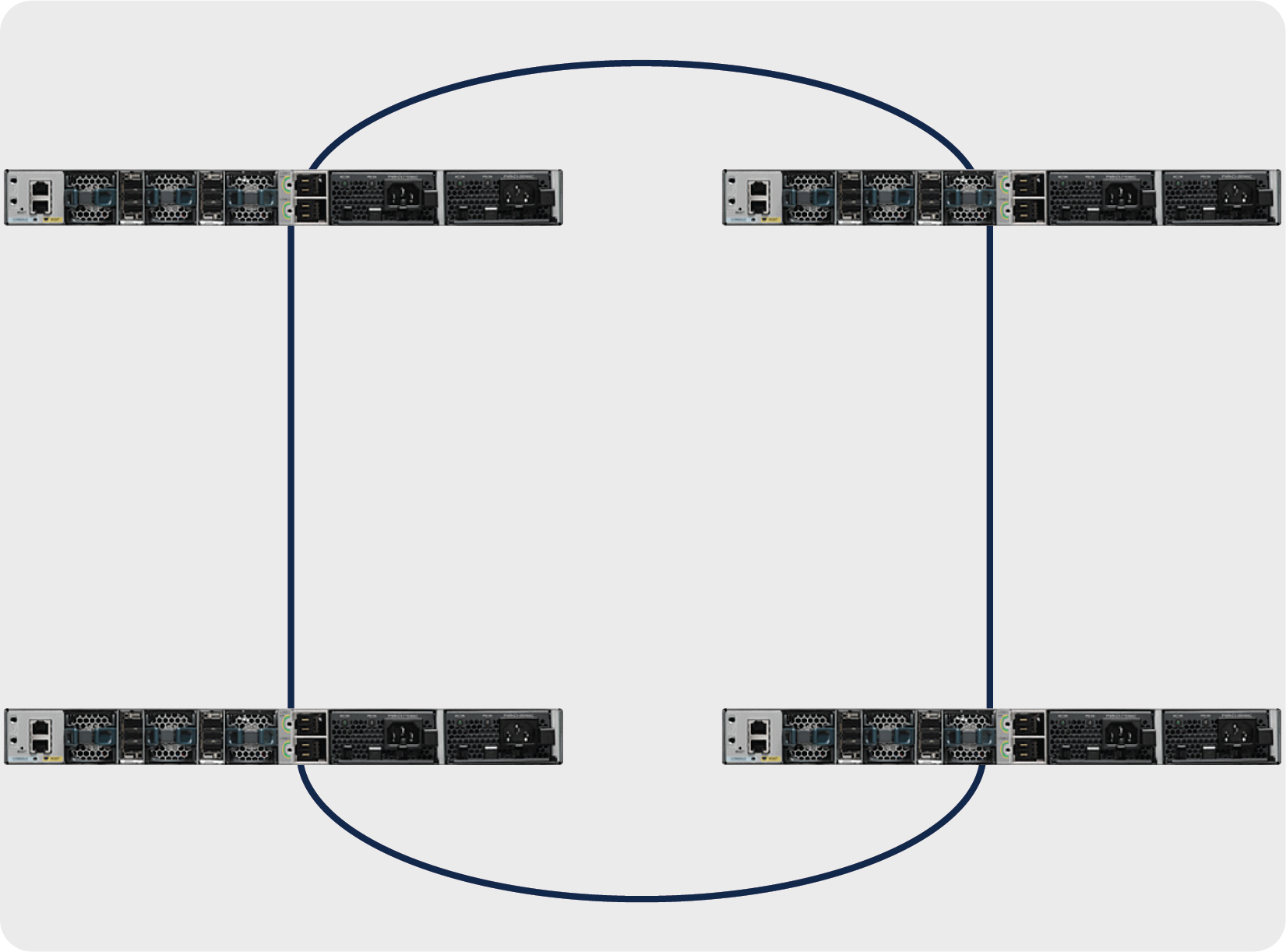
Ring topology
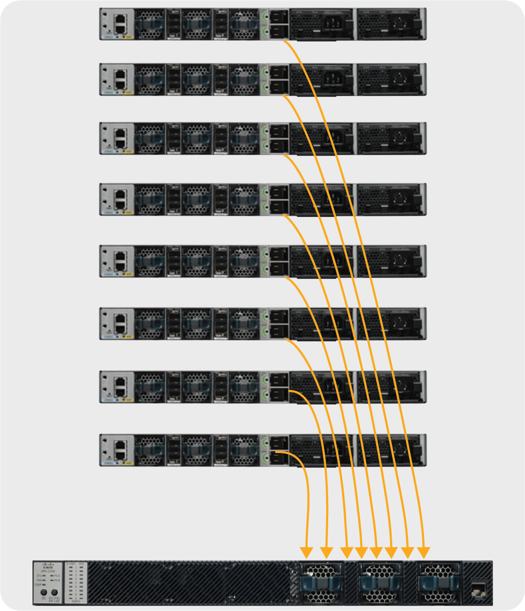
Star topology
The Cisco StackPower cables are thick but flexible, and they carry power as well as a data signal to provide a communications channel among the switches in the power stack. Table 1 lists Cisco StackPower and XPS cables.
Table 1. Cisco StackPower and XPS cables
| Product ID |
Description |
| CAB-SPWR-30CM |
30cm StackPower cable |
| CAB-SPWR-150CM |
150cm StackPower cable |
| CAB-XPS-58CM |
58cm XPS StackPower cable |
| CAB-XPS-150CM |
150cm XPS StackPower cable |
Cisco StackPower and XPS cables are keyed and have colored bands on the ends to help you understand what the connector can plug into.
The cable shown in Figure 6 connects a Cisco Catalyst 9300 Series Switch to another 9300 Series switch in a power stack or to an XPS 2200. It has a green band on one end and a yellow band on the other.
● The cable end with the green band can connect only to a Cisco Catalyst 9300 Series Switch.
● The cable end with the yellow band can connect to a 9300 Series Switch or an XPS 2200.
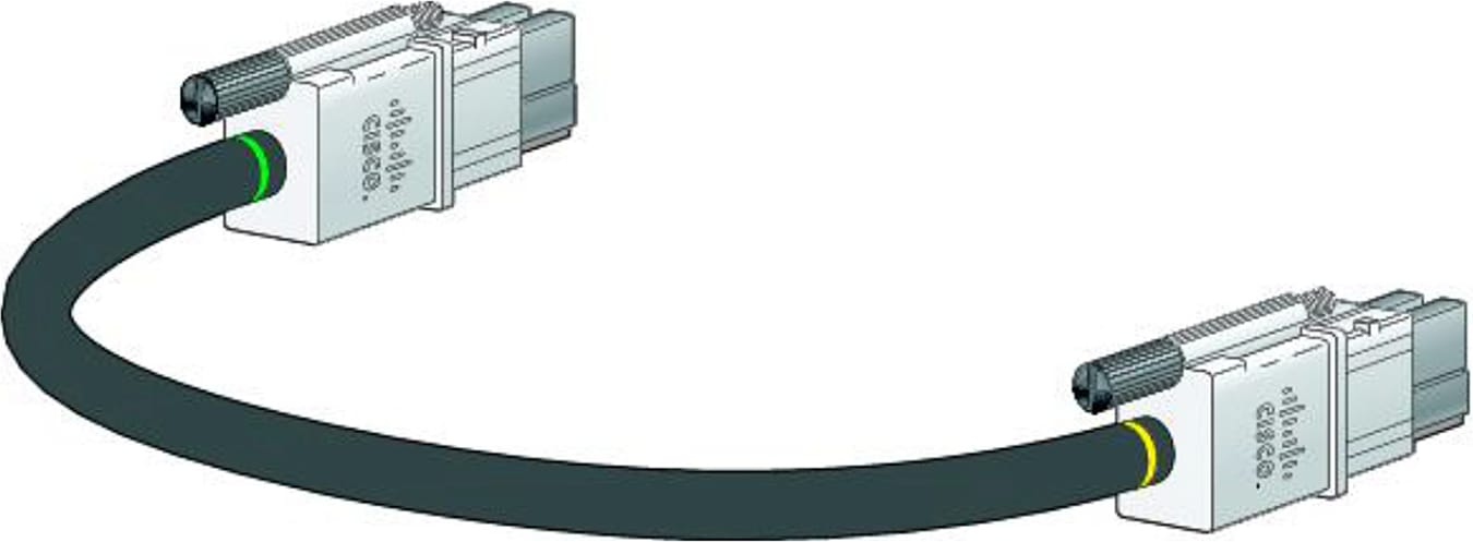
Cisco StackPower cable for use with the Cisco Catalyst 9300 Series Switches
Before connecting the switches in a power stack, follow these guidelines:
● A switch power stack can include a maximum of four switches in a ring topology and eight switches in a star topology with the XPS 2200.
● Size of the switch and any optional power-supply module: The 1100W power-supply module is 1.5 inches (3.81 cm) longer than the other modules, and with the attached cable retention clip, it extends 3 inches (7.62 cm) from the switch chassis. Stacking switches with the same power-supply modules together makes it easier to cable the switches.
● Length of cable: Depending on the configurations that you have, you might need different-sized cables. If you do not specify the length of the Cisco StackPower cable, the 0.3-meter cable is supplied. If you need the 1.5-meter cable, you can order it from your Cisco supplier. For cable part numbers, refer to Table 2. The figures that follow provide examples of recommended Cisco StackPower cabling configurations.
Figure 7 shows a ring configuration using both of the supplied 0.3-meter Cisco StackPower cables and one 1.5-meter cable. In this example, the switches are stacked in a vertical rack.
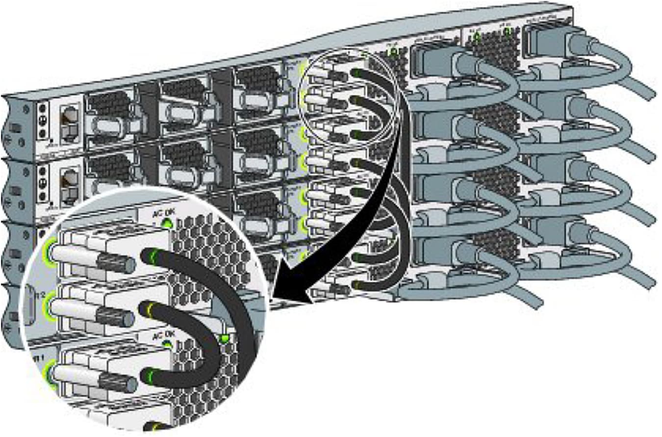
Cisco StackPower ring topology
Figure 8 shows a star topology configuration. In this example, the switches are stacked in a vertical rack.
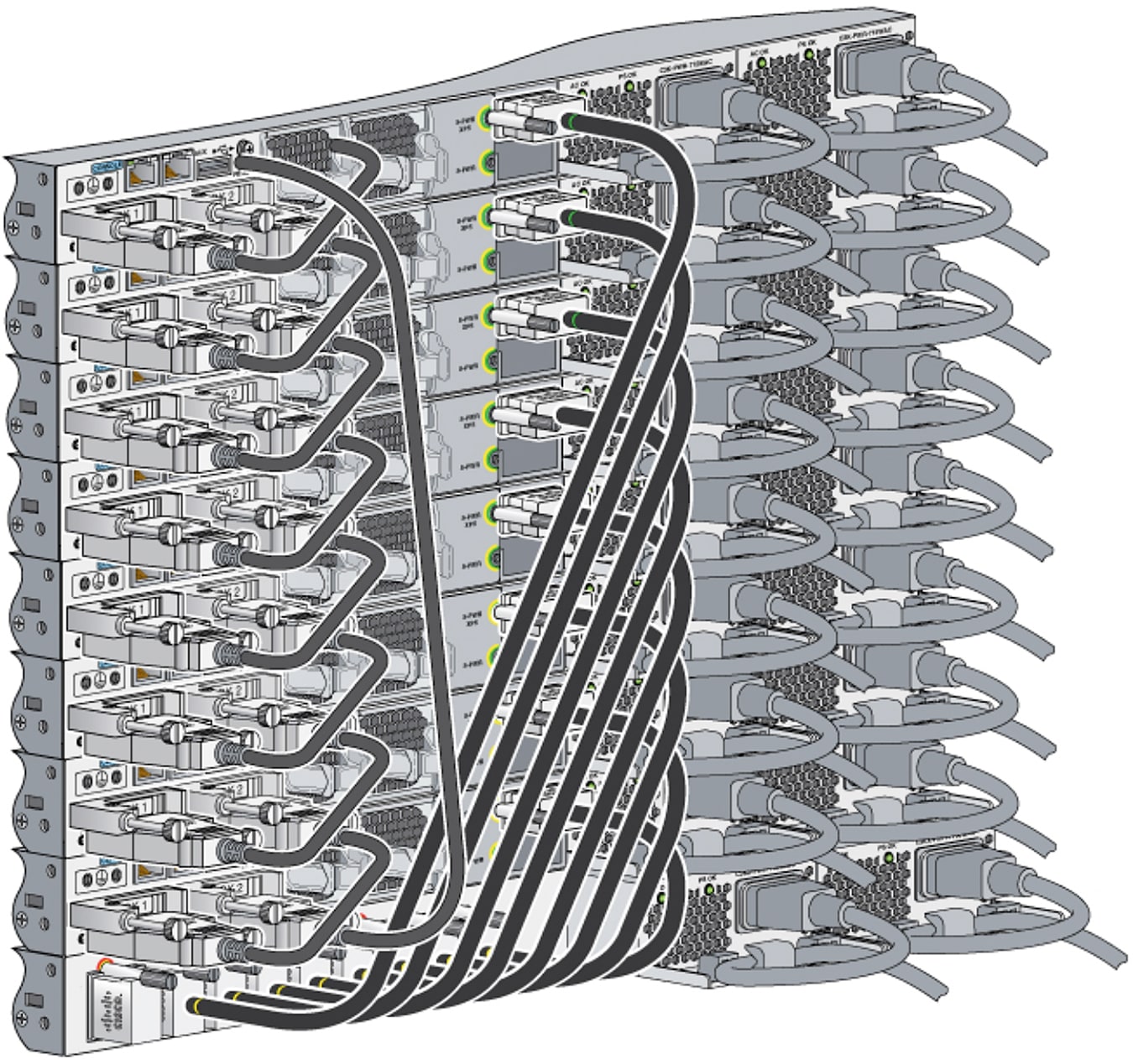
Cisco StackPower star topology
The Cisco Catalyst 9300 Series Switches come with multiple power-supply options, and you can use any of them on any switch in a stack, in any combination. Table 2 lists these options.
Table 2. Power-supply options for the Cisco Catalyst 9300 Series Switches
| Product ID |
Description |
| PWR-C1-350WAC |
350W AC power supply |
| PWR-C1-715WAC |
715W AC power supply |
| PWR-C1-1100WAC |
1100W AC power supply |
| PWR-C1-715WDC |
715W DC Power supply |
| PWR-C1-350WAC-P |
350W AC power supply (Platinum rated) |
| PWR-C1-715WAC-P |
715W DC Power supply (Platinum rated) |
| PWR-C1-1100WAC-P |
1100W AC power supply (Platinum rated) |
The Cisco Catalyst 9300 Series Switches provide two slots for redundant power supplies, but only one supply is needed to run a single switch unless full PoE+ is deployed on a 48-port switch. In that case, the power requirement is greater than 1700W, which is more than the 1100W provided by the largest available power supply. If the switch is deployed within a Cisco StackPower stack, a second power supply might not be needed if the stack has extra power to meet the requirements of this switch, though the power-supply slot must be covered to maintain proper airflow.
You can mix the power-supply types either in a standalone switch or in a stack. That is, you can combine a 350W AC power supply (the default for a data-only switch) with a 715W or 1100W AC power supply (the default in a full PoE switch) or with a 715W DC power supply.
The following are some important concepts for Cisco StackPower technology:
● Cisco StackPower is responsible for negotiating and distributing power from a common power pool among the switches participating in the power stack.
● Intelligent load shed is a mechanism used by Cisco StackPower to decide what devices must power down when the available power drops below the allocated power levels. A priority scheme is used to set different levels, which become useful when:
◦ Load shedding is needed due to the power budget falling below the allocated power levels.
◦ An initial allocation of power is needed to boot up into Cisco IOS XE Software. You can change priorities for powered devices and switches to values other than the preconfigured default values.
● The physical placement of power supplies in a switch is independent of the power required for that switch as long as the best practices are followed. (Refer to Best practices section).
● The power stack reports all of the Cisco StackPower information to the stack master; therefore, configuring a power stack that spans multiple data stacks is not recommended (see the “Best practices” section).
Power stack of four switches
The following use case will help you understand Cisco StackPower technology and its main features.
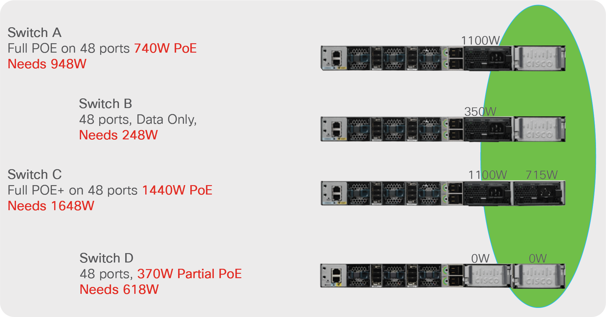
Switches A, B, C, and D, shown in Figure 9, have the following configuration and power draw requirements.
● Switch A requires 948W [PoE + Switch Power Consumption] to provide full PoE on all of its 48 ports. It has only one 1100W power supply; capacity of 152W is available.
● Switch B requires 248W, since it is a non-PoE switch. It has only one 350W power supply; extra power capacity of 102W is available.
● Switch C requires 1648W [PoE + Switch Power Consumption]. It has one 1100W and one 715W power supply; extra power capacity of 167W is available.
● Switch D requires 618W to provide partial PoE on some ports. This switch does not have any power supply, and it requires 618W of power.
These switches have been cabled up to form a power stack to make use of unused power from switches with lower power requirements. This flexible use of available resources is the key benefit of Cisco StackPower technology.
Let’s summarize the scenario:
Power requirements for the power stack:
Switches A through D = 948W + 248W + 1648W + 618W = 3462W
Available power in the common pool of the power stack:
Switches A through D = 1100W + 350W + 1100W + 715W = 3265W
Power deficit = -197W
Although the power stack in the example has extra capacity that gets placed in the power pool, it is not sufficient to power switch D and the PoE devices attached to it. To balance the system and achieve a positive power budget, we must add more power to the stack; a 350W power supply will solve the problem, but it must be installed in slot A of switch D (see the “Best Practices” section). With the addition of a 350W power supply, we will have a positive power budget, with 153W left over in case switches B or D require more power.
Cisco StackPower technology provides the ability to share and redirect surplus power from switch C to switch D, which does not have any power supply. Note that switch D even boots up without a power supply, because the technology allocates and directs power to it. Please review the Best practices section for recommended Deployments.
Cisco StackPower can also provide redundancy without the extra rack unit in the rack. By adding one 1100W power supply to any of the open slots in the power stack, you can configure reserved power to be used if any power supply in the stack fails. This feature is called a zero-footprint redundant power supply.
Displaying Cisco StackPower information
You can use the Cisco IOS XE Software Command-Line Interface (CLI) to view details on Cisco StackPower, such as configured mode, port status, neighbor information, and power requirements, as well as default and configured priorities.
“show stack-power”
9300-STACK#show stack-power detail
Power Stack Stack Stack Total Rsvd Alloc Unused Num Num
Name Mode Topolgy Pwr(W) Pwr(W) Pwr(W) Pwr(W) SW PS
-------------------- ------ ------- ------ ------ ------ ------ --- -
Powerstack-1 SP-PS Ring 5115 35 1180 3900 4 5
Power stack name: Powerstack-1
Stack mode: Power sharing
Stack topology: Ring
Switch 1:
Power budget: 1200
Power allocated: 240
Low port priority value: 20
High port priority value: 11
Switch priority value: 2
Port 1 status: Connected
Port 2 status: Connected
Neighbor on port 1: Switch 4 - dcf7.199a.5e80
Neighbor on port 2: Switch 2 - 046c.9d1f.3400
Switch 2:
Power budget: 1230
Power allocated: 240
Low port priority value: 19
High port priority value: 10
Switch priority value: 1
Port 1 status: Connected
Port 2 status: Connected
Neighbor on port 1: Switch 1 - 046c.9d1f.3b80
Neighbor on port 2: Switch 3 - 046c.9d1f.6c00
Switch 3:
Power budget: 1230
Power allocated: 240
Low port priority value: 21
High port priority value: 12
Switch priority value: 3
Port 1 status: Connected
Port 2 status: Connected
Neighbor on port 1: Switch 2 - 046c.9d1f.3400
Neighbor on port 2: Switch 4 - dcf7.199a.5e80
Switch 4:
Power budget: 1420
Power allocated: 460
Low port priority value: 22
High port priority value: 13
Switch priority value: 4
Port 1 status: Connected
Port 2 status: Connected
Neighbor on port 1: Switch 3 - 046c.9d1f.6c00
Neighbor on port 2: Switch 1 - 046c.9d1f.3b80
The output of the “show environment power all” command shows the power supplies included in power sharing. In the example below, switch 1 has no power supplies installed, switch 2 has an 1100W and a 715W power supply, switch 3 has two 1100W power supplies, and switch 4 has one 1100W power supply.
9300-STACK#sh environment power all
SW PID Serial# Status Sys Pwr PoE Pwr Watts
-- ------------------ ---------- --------------- ------- ------- ----
1A Not Present
1B Not Present
2A PWR-C1-1100WAC LIT21212WAR OK Good Good 1100
2B PWR-C1-715WAC LIT211549FX OK Good Good 715
3A PWR-C1-1100WAC LIT21212NFY OK Good Good 1100
3B PWR-C1-1100WAC DTN2145V53F OK Good Good 1100
4A PWR-C1-1100WAC-P ART2216FDQJ OK Good Good 1100
4B Not Present
The “show stack-power budgeting” command will give you a clean picture of the total power, allocated power, and unused power, as shown below.
9300-STACK#show stack-power budgeting
Power Stack Stack Stack Total Rsvd Alloc Unused Num Num
Name Mode Topolgy Pwr(W) Pwr(W) Pwr(W) Pwr(W) SW PS
-------------------- ------ ------- ------ ------ ------ ------ --- --
Powerstack-1 SP-PS Ring 5115 35 1180 3900 4 5
Power Stack PS-A PS-B Power Alloc Avail Consumd Pwr
SW Name (W) (W) Budgt(W) Power(W) Pwr(W) Sys/PoE(W)
-- -------------------- ----- ----- -------- -------- ------ -----------
1 Powerstack-1 0 0 1200 240 960 129 /0
2 Powerstack-1 1100 715 1230 240 990 131 /0
3 Powerstack-1 1100 1100 1230 240 990 127 /0
4 Powerstack-1 1100 0 1420 460 960 143 /0
-- -------------------- ----- ----- -------- -------- ------ ----------
Totals: 1180 3900 530 /0
The command below shows the switches’ priorities, and the number of high- and low-priority ports for each.
9300-STACK#sh stack-power load-shedding
Power Stack Stack Stack Total Rsvd Alloc Unused Num Num
Name Mode Topolgy Pwr(W) Pwr(W) Pwr(W) Pwr(W) SW PS
-------------------- ------ ------- ------ ------ ------ ------ --- ---
Powerstack-1 SP-PS Ring 5115 35 1180 3900 4 5
Power Stack Priority Consumd Consumd Consumd Alloc Alloc
SW Name Sw-Hi-Lo Sw(W) Hi(W) Lo(W) Hi(W) Lo(W)
-- -------------------- -------- ------- ------- ------- ----- -----
1 Powerstack-1 2-11-20 129 0 0 0 0
2 Powerstack-1 1-10-19 131 0 0 0 0
3 Powerstack-1 3-12-21 127 0 0 0 0
4 Powerstack-1 4-13-22 143 0 0 0 0
-- -------------------- -------- ------- ------- ------- ----- -----
Totals: 530 0 0 0 0
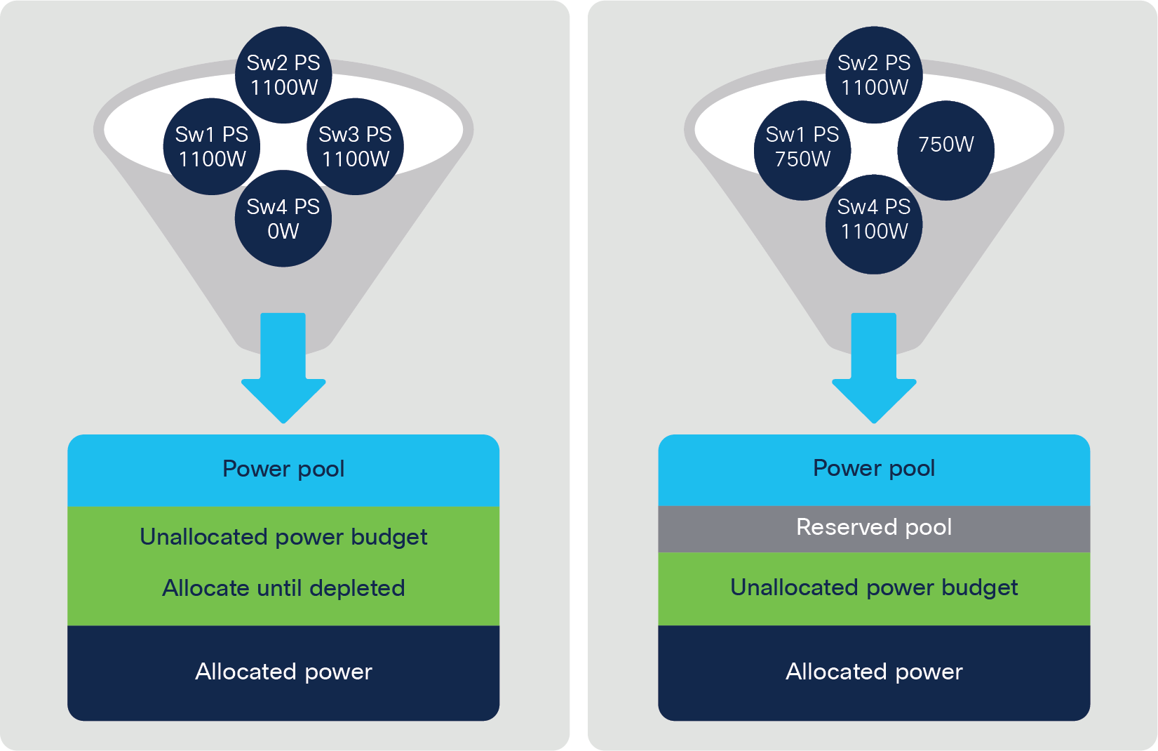
Placing all of the available power in a single pool has advantages: a load (the switches in the power stack and their respective powerable devices) is applied to the pooled power, making efficient use of the power resources of the stack. An administrator may conclude that too much power is available in one stack and may decide to take a power supply offline or pull it out and deploy it somewhere else.
A traditional power supply reaches around 80 percent efficiency when the applied load is 60 percent and tops out at a load of perhaps 80 percent; therefore, to make the best possible use of power, it is a good idea to apply all of the load to a single power supply to reach higher efficiency more quickly before powering up a second power supply, and so on.
A more energy-efficient scenario could involve the same four switches drawing power from the same source, as in a power stack. Four switches have a higher chance of reaching the optimal load on the power supply so the maximum efficiency can be reached sooner, translating into energy savings and more intelligent use of power. Note that Cisco IOS Software has the knobs to take a power supply offline and place it back online as required, and Cisco StackPower has the instrumentation to provide the information needed to take an action, but offlining a power supply requires administrator intervention.
A maximum of 8400W is possible in a pool of power in a stack of four switches loaded with two 1100W power supplies each. This is obviously sufficient, even if the stack consists of four Cisco Catalyst 9300-48U switches requiring 30 ports of Cisco UPOE or full PoE+. Consider the math:
4 switches x 30 ports x 60W = 7200W. This ls less than the available 8400W.
If only one power supply is installed in each switch, we get 4400W in the power pool. Now we fall short, but the reality is that not everyone needs full Cisco UPOE on every port in a stack of four switches; hence, 4400W may be just fine. Here is where Cisco StackPower starts to provide savings by allowing the administrator to purchase power supplies as the need for power grows.
The Cisco StackPower technology can be deployed in a ring topology as well as in a star topology over an XPS 2200, as shown earlier in Figures 7 and 8. Both topologies have advantages and disadvantages. A ring topology provides greater resiliency, because current can flow in either direction in the ring if a path fails. On the other hand, the number of switches in the ring topology is restricted to four, to ensure safety and prevent large currents through the cables. Some deployment scenarios create large currents that would require a larger gauge of wire in the Cisco StackPower cables, which reduces the manageability of the cables. Nonetheless, a stack of four is a common deployment.
The star topology has no such restriction; all eight switches can share power through the XPS 2200, although one more piece of hardware is installed in the rack among the switches.
Cisco expandable power system (XPS 2200)
The XPS 2200 is the next-generation redundant power system, providing redundancy for up to eight Cisco Catalyst 9300 Series Switches as well as Cisco StackPower capability for up to eight 9300 Series switches.
A StackPower Power Stack (Ring and Star) can be configured to operate in one of four different global modes, which effectively select the choices for two different criteria (non-strict mode and strict mode). Every switch in the Power Stack operates in the same mode as part of the stack. The modes of operation are:
● Power-sharing mode (non-strict)
● Power-sharing mode strict
● Redundant mode (non-strict)
● Redundant mode strict
When a Power Stack is formed (via cable connections or when switches are booted), if there are conflicts amidst the switches and not all switches have the same Power Stack Mode in their configuration, precedence is given to Power Shared mode over Redundant mode, and Non-Strict mode has precedence over Strict.
● In power-sharing mode (the default), all input power is available to be used for power loads. The total available power in all switches in the power stack (up to four) is treated as a single large power supply, with power available to all switches and to all powered devices connected to PoE ports. In this mode, the total available power is used for power budgeting decisions, and no power is reserved to accommodate power-supply failures. If a power supply fails, powered devices and switches could be shut down (load shedding).
● In redundant mode, the power from the largest power supply in the system is subtracted from the power budget, reducing the total available power but providing backup power if a power supply fails. Although less power is available in the pool for switches and powered devices to draw from, this mode reduces the possibility of having to shut down switches or powered devices in case of a power failure or extreme power load.
The following example illustrates the difference between these various modes:
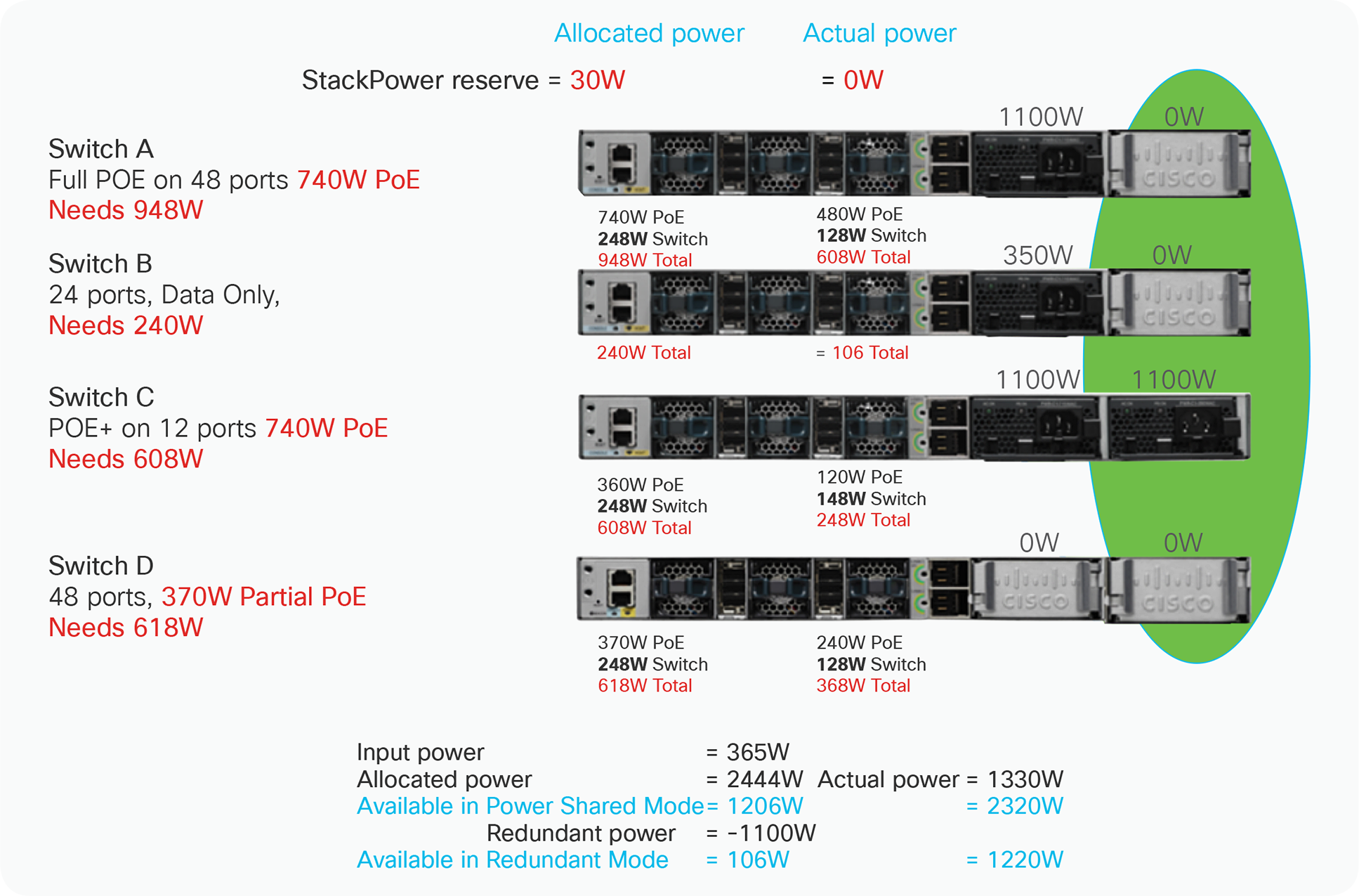
Power Stack of Four Switches.
Switches A, B, C, and D have the following configuration and power draw requirements:
● The StackPower Ring itself requires a 30W Reserve budget.
● Switch A requires 740W for full PoE and 248W to power its switch. Since it has only one 1100W power supply, there is an extra 152W of capacity added the to Unused power budget.
● Switch B requires 240W for a 24 port non-PoE switch. Since it has only a 715W power supply, there is an extra 475W of capacity added to the Unused power budget.
● Switch C requires 360W for 12W of PoE+ and 248W for the switch. Since it has an 1100W supply, there is an extra 1592W of capacity added to the Unused power budget.
● Switch D requires 370W for Partial PoE and 248W for the switch. Since it has no power supplies, it will consume all of its power from the ring – drawing down the Unused power budget.
Power shared Vs. Redundant budgeting modes:
The default configuration is power-sharing mode nonstrict. Of course, you have the option of configuring strict mode, which would keep you from creating a negative power budget. The same is true for redundant mode.
Take the example in Figure 10, in Power Share (non-redundant) Mode the budget is such that the Input Power is 3650W, the Allocated Power is 2444W, and therefore the Unused Power is 1206W.
In the same configuration but in Redundant Mode, the budget is such that the Unused Power is now decreased by the 1100W Redundant Power, making it 106W.
Power shared mode Vs. redundant mode
Strict Vs. Non-Strict Enforcement modes:
You can configure the mode to run a strict power budget or a nonstrict power budget. In both modes, power is denied when no more power is available in the power budget.
● In strict mode, when a power supply fails and the available power drops below the budgeted power, the system balances the budget through load shedding of powered devices, even if the actual power being consumed is less than the available power.
● In nonstrict mode, the power stack is allowed to run in an overallocated state and is stable as long as the actual power does not exceed the available power. In this mode, a powered device drawing more than normal power could cause the power stack to start shedding loads. This situation is normally not a problem because most devices do not run at full power and the chances of multiple powered devices in the stack requiring maximum power at the same time is small.
Taking again the example above in Figure 10, where the Actual Power is significantly less than what was Allocated (2444W v. 1330W). If, for example, both an 1100W and 715W supply failed, the Allocated Power figure of 2444W would exceed the Input Power mark of the remaining 2*1100W (2200W) Power supplies and the Power Stack would be operating “over budget.” Because the Actual Power is still 870W less than the Input Power from the power supplies, no hardware load sheds would be necessary in this case.
However, if the Power Stack Mode is set to be Power Shared Strict or Redundant Strict (i.e., Strict Enforcement mode is enabled), then IOS Software will strictly enforce the power budgets and require that Allocated Power be equal to or less than Input Power, resulting in Load Shedding where power is taken away from sets of lowest priority PoE ports until the Allocated Power total is less than or equal to 2200W. Until there is budget again, PoE power will also be denied to any new PDs trying to classify, as well.
In Power Shared and Redundant modes, (i.e., Non-Strict Enforcement), no action would be taken at all in this case, and the Power Stack would be allowed to run over-budget (more Allocated Power than Input Power, but less Actual than Input Power). The added risk in this scenario is that a hardware-triggered load shed is entirely possible based on nothing other than increases in PoE power consumption (i.e., Actual Power increases). This could happen if a bunch of users decided to pick up their phones and make phone calls at the same time, for example.
It is assumed that, for most PoE SKUs, the Power Shared and Non-Strict Modes would be preferable since, especially with PoE PDs, the Allocated Power will be significantly greater than the Actual Power and, therefore, it may be likely that a failure would not require load shedding even in this most aggressive mode. However, each customer should analyze their particular situation to find the right balance between energy efficiency, TCO, and resiliency/redundancy.
You configure power modes at a power-stack level (that is, the mode is the same for all switches in the power stack).
You can also configure a switch connected in a power stack to not participate in the power stack by setting the switch to standalone power mode using the command below. This mode shuts down both Cisco StackPower ports.
9300-STACK#conf t
Enter configuration commands, one per line. End with CNTL/Z.
9300-STACK(config)#
9300-STACK(config)#stack-power switch 1
9300-STACK(config-switch-stackpower)#standalone
The Cisco StackPower feature enables intelligent management of not only the power resources of a stack but also power failures.
Load shedding is the process of shutting down devices if a power supply, cable, or system fails. For power stacks in power-sharing mode, there are two types of load shedding: immediate and graceful.
● Immediate load shedding occurs when a failure could cause the power stack to fail very quickly, for example, a massive power failure in which multiple power supplies go offline for any reason and the available power cannot sustain the system.
● Graceful load shedding can occur when a power supply fails and forces the power stack to reevaluate its power allocations. Switches and powered devices may shut down in order of their default or configured priority, starting with devices with priority 27, until the power budget matches the input power.
Graceful load shedding is always enabled, and immediate load shedding occurs only when necessary.
Notes on load shedding:
● The method (immediate or graceful) is not user configurable but is based on the power budget.
● Immediate load shedding also occurs in the order of configured priority, but it occurs very quickly to prevent hardware damage caused by loss of power.
● If a switch is shut down because of load shedding, the output of the show stack-power detail privileged EXEC command still includes the MAC address of the shut-down switch as a neighbor switch, even though the switch is down. This command output shows the Cisco StackPower topology, even if there is not enough power to power up a switch.
What is a balanced power stack? A balanced power stack is one that has a positive power budget; in other words, the available power is equal to or greater than the allocated power.
Balanced power budget: Available power > Allocated power
When a power stack suffers a power-supply failure, the available power budget drops, and if “strict” power-sharing mode has not been configured, the result is a negative power budget, causing the system to become unbalanced.
Negative power budget: Available power < Allocated power
If the allocated power is not currently being consumed, nothing would happen other than Cisco IOS XE Software messages appearing on the console, but as soon as PoE devices demand the allocated power, the system will start a load-shedding process until the power budget is balanced again.
The design of the Cisco Catalyst 9300 Series Switches includes hardware to assign a priority to every port in the switch. This hardware allows us to tag ports for high and low priorities, which are set by default but can be programmed by the administrator. These priorities are used only when the switch or the stack needs to shed power to bring the system back into balance. Cisco IOS Software will generate plenty of console messages to inform the administrator about the situation.
Priority scheme
Cisco StackPower has a priority scheme that covers up to eight switches in a data stack and all of the ports in the entire stack.
Priorities are set by default when the power stack gets created, but you can configure the priority in which a switch or powered device receives power (Figure 14). This priority determines the order in which devices are shut down if a power shortage occurs and graceful load shedding takes place. You can configure three priorities per system: the system (or switch) priority, the priority of the high-priority PoE ports on a switch, and the priority of the low-priority PoE ports on a switch.
You can set port priority at the interface level for powered devices connected to a PoE port. By default, all ports are low priority.
The Cisco Catalyst 9300 Series has the capability to create two groups of ports, high priority and low priority (Figure 14). High-priority ports are those connected to more important or critical powered devices and are preferred to retain inline PoE power in case of a power shortage. Cisco StackPower technology or the administrator assigns a priority level to those groups of ports.
You can configure the priority values of each switch in the power stack and all high- and low-priority ports on that switch to set the order in which switches and ports are shut down when power is lost and load shedding must occur. Priority values are from 1 to 27; switches and ports with the highest values are shut down first (Figure 15).
Switch priority, high port priority, and low port priority can be manually configured using the following commands.
9300-STACK#conf t
Enter configuration commands, one per line. End with CNTL/Z.
9300-STACK(config)#stack-power switch 3
9300-STACK(config-switch-stackpower)#power-priority switch 3
9300-STACK(config-switch-stackpower)#power-priority high 10
9300-STACK(config-switch-stackpower)#power-priority low 20
9300-STACK(config)#end
Any interface can be grouped into either a high priority or low priority using the following command at the interface level
9300-STACK(config)#int GigabitEthernet1/0/1
9300-STACK(config-if)#power inline port priority ?
high high prority port
low low prority port
On any switch, the switch priority value must be lower than the port priority values, and the high-priority value must be set lower than the low-priority value. We recommend that you configure a different priority value for each switch and for its high- and low-priority ports. This configuration limits the number of devices shut down at one time during a loss of power. If you try to configure the same priority value on different switches in a power stack, the configuration is allowed, but you will receive a warning message.
The default priority ranges, if none are configured, are 1 to 9 for switches, 10 to 18 for high-priority ports, and 19 to 27 for low-priority ports.
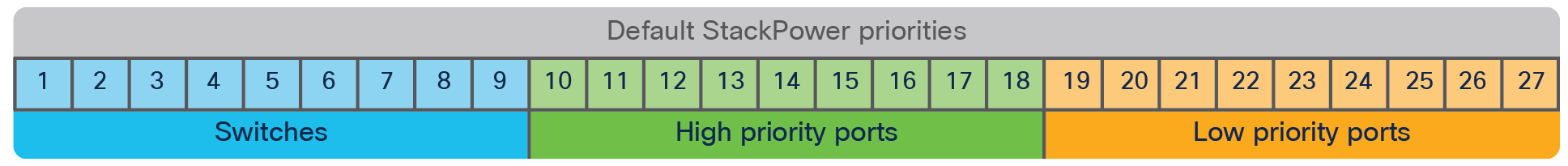
Default Cisco StackPower priorities
Figure 12 shows the default priorities that Cisco StackPower technology uses and that an administrator can overwrite. As an example, a power stack can assign priority 2 to switch A, priority 10 to high-priority ports, and priority 20 to low-priority ports. Each switch in the stack will have a different priority set for the switch, the high-priority ports, and the low-priority ports, respectively. The priority levels are not repeated on any switch or port. In other words, if load shedding is required on switch A with priority level 10 for its high-priority ports, all other switches in the stack will have to shed their low-priority ports (priority 19 to 27) and their high-priority ports (priority 11 to 18) before switch A has to shed PoE power on its high-priority ports, because it has the highest priority level (10) for its high-priority ports.
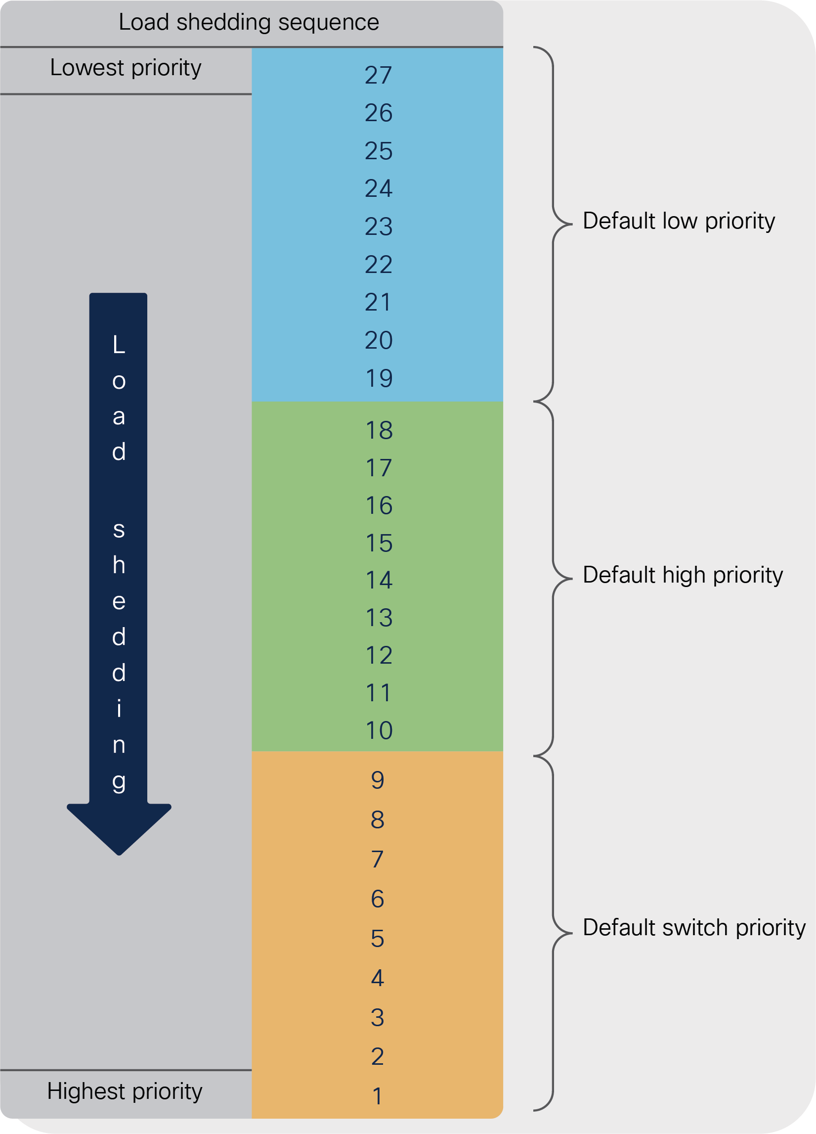
Load shed sequence
Cisco IOS XE Software can monitor administrator priority settings to make sure that a high-priority port in switch A cannot have a lower priority level than a low-priority port on another switch in the stack.
As an administrator you can select any priority level for your switches and devices, as long as you keep the hierarchy of the switches, high-priority ports, and low-priority ports in such a way that a high-priority port will not be shed before a low-priority port.
Cisco StackPower is an innovative technology that allows for the flexible and efficient use of the power resources in a stack of switches. Such an orchestration of hardware capabilities, resources, and features requires us to follow certain practices to ensure the proper and best use of this technology.
We recommend that you:
● Balance the power stack: To ensure that a severely Input/Load Imbalanced Power Stack is not created, ensure the following rules are followed:
a. Available v. Allocated power: Make sure that the load off any single system is no more than 1000W over the amount of Input Power locally deployed in that system. For example, if a System in a Ring has a 350W power supply, then the load at that system should be no more than 1350W (e.g., 223W for the Switch and 1127W PoE).
b. Input Supplies: Install one in all before two in any. In other words, never have two power supply slots filled in any system before you have at least one supply in all the systems of a Power Stack. Another easy way to remember it is to fill all of the “A” slots before you fill any of the “B” slots.
Power-supply slots are named left to right; that is, power-supply slot A is on the left and power-supply slot B is on the right (closest to the edge of the switch).
Following these simple rules allows for deployments that mitigate what would otherwise be unnecessary load shedding. That is to say, not following these rules could lead to deployments where, for example, a single cable cut could cause load shedding that would otherwise not occur. It also eliminates any case where simple load imbalances (without any equipment failures) would cause load shedding.
As can be seen in Figure 14, that if these rules are not followed, pathologically unbalanced cases can be created where, for example, the switches on the right side have little Input Power but large Actual Power, whereas the switches on the left side have little Actual Power but large amounts of Input Power. During normal operation this would be fine – about 30A would flow through both the top and the bottom cable, equally. However, if a failure occurs that disables the top cable, 60A would be required to flow through the single bottom StackPower cable, when the cables are safety rated to carry only 55A in the worst-case. The StackPower circuitry would quickly detect this overcurrent and load shed so as to remain safe. By following the rules above this scenario would not be possible – as it violates both1a and 1b.
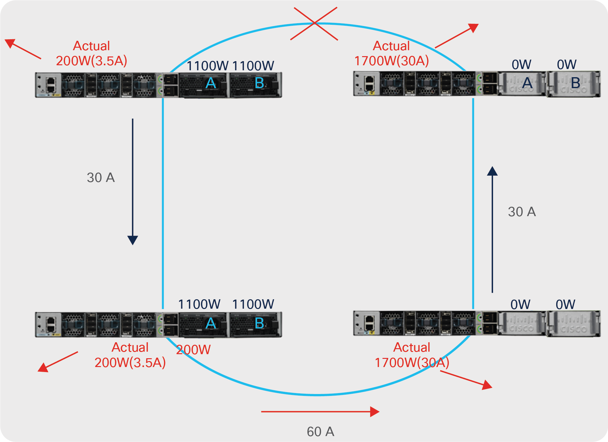
Unbalanced power stack
● Do not configure power stacks that span across data stacks.
Cisco StackPower is limited to four switches per power stack, although one data stack of eight switches can be configured over multiple power stacks; this is a supported deployment. A Data Stack of Eight switches can be deployed as two power stacks of four switches.
● Configure strict modes and do not allow the power stack’s available power budget to go negative. Strict mode is not the default for the power sharing or redundant modes, but we recommend that you configure strict mode to force the system to shed loads as soon as the power budget falls below the allocated power, even if the power is not needed at that precise moment.
● Changing Cisco StackPower modes is possible without reloading the Power Stack. There is no need to reload either the Power Stack or any of its members; nonetheless caution must be exercised when deciding to switch from Power-Sharing Mode to Redundant Mode. The reason is that although the power budget may be sufficient to sustain the power stack in power-sharing mode, it may not be enough to support redundant mode, which requires enough extra power in the budget to equal the largest power supply in the power stack. An insufficient power budget will cause a load shed of PoE devices and even switches in the power stack.
We recommend first calculating the required power in the power stack and adding the amount of power to be reserved (the size of the largest power supply in the power stack) and comparing the requirement with the available power in the power stack.
● Taking power supplies offline is supported but is not automatic. Cisco IOS XE has the necessary commands to manage the power supplies, and administrator intervention is required due to the multiple use cases that can be derived. Cisco IOS XE has multiple warning messages to prevent an unbalanced power stack.
We recommend analyzing the deployment to make sure that turning off a power supply will not break any of the rules or recommendations stated earlier, such as filling in slot A of each switch in the stack before installing a power supply in slot B. Turning off a power supply would have an effect similar to removing the power supply.